US4813406A - Orthopedic splint arrangement - Google Patents
Orthopedic splint arrangementDownload PDFInfo
- Publication number
- US4813406A US4813406AUS06/877,897US87789786AUS4813406AUS 4813406 AUS4813406 AUS 4813406AUS 87789786 AUS87789786 AUS 87789786AUS 4813406 AUS4813406 AUS 4813406A
- Authority
- US
- United States
- Prior art keywords
- splint device
- splint
- device defined
- base portion
- support members
- Prior art date
- Legal status (The legal status is an assumption and is not a legal conclusion. Google has not performed a legal analysis and makes no representation as to the accuracy of the status listed.)
- Expired - Fee Related
Links
- 230000000399orthopedic effectEffects0.000title1
- 230000000452restraining effectEffects0.000claimsabstractdescription13
- 230000006835compressionEffects0.000claimsdescription81
- 238000007906compressionMethods0.000claimsdescription81
- 235000001674Agaricus brunnescensNutrition0.000claimsdescription25
- 230000002093peripheral effectEffects0.000claimsdescription9
- 230000008878couplingEffects0.000claimsdescription4
- 238000010168coupling processMethods0.000claimsdescription4
- 238000005859coupling reactionMethods0.000claimsdescription4
- 230000003100immobilizing effectEffects0.000claimsdescription4
- 238000001035dryingMethods0.000claimsdescription2
- 239000000463materialSubstances0.000description12
- 210000003371toeAnatomy0.000description9
- 208000027418Wounds and injuryDiseases0.000description5
- 208000014674injuryDiseases0.000description5
- 238000009434installationMethods0.000description5
- 230000006378damageEffects0.000description4
- 208000010392Bone FracturesDiseases0.000description3
- 210000002683footAnatomy0.000description3
- 208000034656ContusionsDiseases0.000description2
- 206010017076FractureDiseases0.000description2
- 230000006978adaptationEffects0.000description2
- 239000000853adhesiveSubstances0.000description2
- 230000001070adhesive effectEffects0.000description2
- 230000004323axial lengthEffects0.000description2
- 210000000988bone and boneAnatomy0.000description2
- 230000003247decreasing effectEffects0.000description2
- 230000014759maintenance of locationEffects0.000description2
- 238000000465mouldingMethods0.000description2
- 230000008961swellingEffects0.000description2
- XLYOFNOQVPJJNP-UHFFFAOYSA-NwaterSubstancesOXLYOFNOQVPJJNP-UHFFFAOYSA-N0.000description2
- 206010016970Foot fractureDiseases0.000description1
- 206010019114Hand fractureDiseases0.000description1
- 241001465754MetazoaSpecies0.000description1
- 208000006670Multiple fracturesDiseases0.000description1
- 239000004677NylonSubstances0.000description1
- 206010052428WoundDiseases0.000description1
- 238000005452bendingMethods0.000description1
- 230000003749cleanlinessEffects0.000description1
- 230000000295complement effectEffects0.000description1
- 238000010276constructionMethods0.000description1
- 230000000881depressing effectEffects0.000description1
- 239000003814drugSubstances0.000description1
- 230000000694effectsEffects0.000description1
- 238000001704evaporationMethods0.000description1
- 230000008020evaporationEffects0.000description1
- 230000005713exacerbationEffects0.000description1
- 230000035876healingEffects0.000description1
- 238000002347injectionMethods0.000description1
- 239000007924injectionSubstances0.000description1
- 238000007689inspectionMethods0.000description1
- 239000002184metalSubstances0.000description1
- 210000001872metatarsal boneAnatomy0.000description1
- 230000004048modificationEffects0.000description1
- 238000012986modificationMethods0.000description1
- 229920001778nylonPolymers0.000description1
- 239000011505plasterSubstances0.000description1
- 239000004033plasticSubstances0.000description1
- 229920003023plasticPolymers0.000description1
- 229920000915polyvinyl chloridePolymers0.000description1
- 239000004800polyvinyl chlorideSubstances0.000description1
- QQONPFPTGQHPMA-UHFFFAOYSA-NpropyleneNatural productsCC=CQQONPFPTGQHPMA-UHFFFAOYSA-N0.000description1
- 125000004805propylene groupChemical group[H]C([H])([H])C([H])([*:1])C([H])([H])[*:2]0.000description1
- 230000029058respiratory gaseous exchangeEffects0.000description1
- 210000004243sweatAnatomy0.000description1
- 230000008736traumatic injuryEffects0.000description1
- 229920002554vinyl polymerPolymers0.000description1
- 210000000707wristAnatomy0.000description1
Images


Classifications
- A—HUMAN NECESSITIES
- A61—MEDICAL OR VETERINARY SCIENCE; HYGIENE
- A61F—FILTERS IMPLANTABLE INTO BLOOD VESSELS; PROSTHESES; DEVICES PROVIDING PATENCY TO, OR PREVENTING COLLAPSING OF, TUBULAR STRUCTURES OF THE BODY, e.g. STENTS; ORTHOPAEDIC, NURSING OR CONTRACEPTIVE DEVICES; FOMENTATION; TREATMENT OR PROTECTION OF EYES OR EARS; BANDAGES, DRESSINGS OR ABSORBENT PADS; FIRST-AID KITS
- A61F5/00—Orthopaedic methods or devices for non-surgical treatment of bones or joints; Nursing devices ; Anti-rape devices
- A61F5/01—Orthopaedic devices, e.g. long-term immobilising or pressure directing devices for treating broken or deformed bones such as splints, casts or braces
- A61F5/04—Devices for stretching or reducing fractured limbs; Devices for distractions; Splints
- A61F5/05—Devices for stretching or reducing fractured limbs; Devices for distractions; Splints for immobilising
- A61F5/058—Splints
- A61F5/05841—Splints for the limbs
- A61F5/05858—Splints for the limbs for the arms
- A61F5/05875—Splints for the limbs for the arms for fingers
Definitions
- This inventionrelates to the medical arts, and, more particularly, to an improved splint arrangement for immobilizing preselected portions of the body.
- a bone fracturemay require immobilization during the time period when the bone is healing.
- Bruises or other injuries to various members of the bodymay also require immobilization of such body member to prevent exacerbation of the injury or bruises to the body member.
- the splint devices to be used for these purposesare light in weight and of minimal size, to avoid undesired encumbrance, but still provide the desired type of protection and/or immobilization.
- the splint devicesshould be inexpensive to fabricate and use.
- the splint deviceis preferably comparatively quickly and easily installable on and removable from the body member by the appropriate attending personnel. Such a feature facilitates not only the initial installation of the splint device, but also removal thereof with minimal discomfort, so as to allow inspection and/or treatment of the body member. Care must be taken, however, in many applications, to insure that the device is "childproof," that is, not easily removable or manipulatable by children.
- splint deviceswhich may be rapidly installed on the fractured or otherwise injured body member.
- one splint devicebe adaptable to a variety of sizes of body members so that the inventory of the attending personnel may be minimized.
- a semi-rigid constructionis also desired in many applications of a splint device to allow conformation of the splint device to a particular shape of the body member.
- the splint devicemust have sufficient strength and rigidity to provide the protection desired on any specific application.
- U.S. Pat. No. 1,144,103discloses a finger splint consisting of a pair of thin pliable strips, secured together at their centers, to extend at right angles to each other, the strips being bent inwardly toward each other at a point adjacent the center to form an elongated framework, the free ends of said strips being provided with slots.
- U.S. Pat. No. 1,229,633describes a finger guard consisting of a plurality of strips of pliable metal, wire, or other suitable material, twisted about each other upon their approximate centers in such a manner that a plurality of extensions result, which, upon being bent or contoured to the finger, extend in a substantially parallel relation.
- the guardis adapted to be held in place on the member by adjesive strips, cord, or other suitable means.
- U.S. Pat. No. 3,692,022describes a digital splint adapted for use on a finger.
- the splintincludes a generally cylindrical, rigid, hollow member, in which the finger is inserted, and a spring clip member which engages the finger through a pair of mutually opposed slots in the hollow member, and which secures the hollow member to the finger.
- U.S. Pat. No. 2,506,464pertains to what is referred to as a finger stall, comprising a plurality of strips of malleable material, the strips being pivotally held together one upon the other at their central portions, the strips being pivotally turnable out of registry with each other and the ends of the strips being turned in the same direction form U-shaped elements having parallel positioned legs which are pivotally adjustably positionable around an injured member, one leg element is curved transversely to provide stiffness to the leg and to provide a formed curvature in the stall for close fitting around the injured member.
- U.S. Pat. No. 2,022,883Another splint is disclosed in U.S. Pat. No. 2,022,883.
- This splinthas a paddle shaped semi-pliable plate of a material having the inherent quality of being easily bent manually into various forms, and of retaining such forms when so bent.
- the platehas a substantially rectangular blade portion, and a portion of the blade continuing from one end thereof and gradually decreasing in width at one side of its axis and somewhat more abruptly decreasing in width at the other side of its axis. Digits can be bandaged to the blade.
- U.S. Pat. No. 1,245,858relates to a surgical splint consisting of a pair of pliable strips adjustably connected together between their ends and extending at substantially right angles to each other. The strips are bent in parallel relationship for engagement upon a finger.
- the present splint devicemeets the above mentioned desiderata, and is unique in providing a simple device for effective immobilization and protection of a broken or injured body member.
- a splint device according to the principles of the present inventionis adaptable to a wide range of body member sizes and is adjustable thereto and securely retainable thereon. The device does not retain water or perspiration.
- the splint device of the present inventionis inexpensive, comparatively light in weight, of minimal bulk, and may be rapidly and easily installed on the body member. "Childproofing" of the splint device may also be provided.
- splint device described hereinis shown as utilized on human body members, the invention is not so limited. Splint devices of the present invention may also be utilized advantageously in veterinary medicine in treatment of animals.
- the present inventioncomprises a splint device for the immobilization of a body member because of fractures or other injuries to the body member.
- a body membermay, for example, be a digit, such as a finger or toe.
- the splint devicecomprises a splint means comprising a ring-like base portion adapted to fit around a digit in proximity to the digit's proximal end. Extending from the base portion, there is provided a plurality of essentially rigid or semi-rigid elongated support members which are coupled to the base portion of their base ends and are spaced apart around the base portion. The elongated support members are positionable adjacent the contained digit, preferably on more than one of its sides.
- Each of the support membersterminates at a free end which is in the vicinity of, or beyond, the distal end of the digit.
- Support membersmay be "mushroom” type projections and the retaining means may be a comparatively flexible strap.
- the flexible straphas walls defining a mushroom engaging slot and is provided with a plurality of self retaining clasp means thereon to allow adjustment to any desired diameter as it is wrapped around the support members.
- cap meanswhich may be installed over the free ends of the support members for retention thereon.
- the cap meansmay, if desired, be made "childproof" to prevent the undesired removal of the cap means by small children.
- the ring-like base portionsmay be of a fixed diameter or, alternatively, may be provided with radial expansion capability to provide a predetermined circumferential expansion.
- the radial expansion capabilitymay be achieved by axially extending slots, by "zig-zag" interconnections between the support members, or combinations thereof.
- the circumferential expansion characteristicpermits utilization of one sized splint device on a variety of sizes of body members.
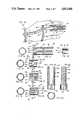
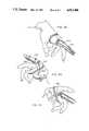
- FIG. 1is a perspective view showing an embodiment of the invention in place on a finger, and immobilizing same;
- FIG. 2is a perspective view showing an embodiment of the present invention in place on a toe
- FIG. 3is a longitudinal sectional view through a finger, showing how it is immobilized by the splint;
- FIG. 4is a side view, partially broken away, of the splint employed in FIG. 3;
- FIG. 5is a side view, partially broken away, of a compression means useful in the embodiment shown in FIG. 3;
- FIG. 6is a view taken along line 6--6 of FIG. 4;
- FIG. 7illustrates an end cap means useful in the practice of the present invention
- FIG. 8is a side and partially broken away view of another embodiment of the invention.
- FIG. 9is a sectional view of another compression means useful in the practice of the present invention.
- FIG. 10is a perspective view of yet another embodiment of the present invention.
- FIG. 11is a side view, in partial section, of another embodiment of the present invention.
- FIG. 12is an end view of the splint of FIG. 11;
- FIG. 13is a side view, in partial section, of another end cap means useful in the practice of the present invention.
- FIG. 14is a partial view, in partial section, of another embodiment of the present invention.
- FIG. 15is a sectional view along the line 15--15 in FIG. 14;
- FIG. 16is a partial view in partial section of still another embodiment of the present invention.
- FIG. 17is a sectional view, taken along the line 17--17 in FIG. 16;
- FIG. 18is a partial view, in partial section, of another embodiment of the present invention.
- FIG. 19is a sectional view, taken along the line 19--19 in FIG. 18;
- FIG. 20is a partial view, partially in section, of another embodiment of the present invention.
- FIG. 21is a side view of another embodiment of a splint of the present invention.
- FIG. 22is a side view 90° disposed from the view of FIG. 20, and shows breathing and drain holes;
- FIG. 23illustrates another compression means useful in the practice of the present invention
- FIGS. 24 and 25illustrate another embodiment of the present invention
- FIGS. 26, 27, and 28illustrate another embodiment of the present invention
- FIG. 29illustrates another end cap means useful in the practice of the present invention.
- FIG. 30illustates another compression means useful in the practice of the present invention.
- FIGS. 31, 32, and 33illustrate another compression mean useful in the practice of the present invention.
- FIG. 34is a side view of element 252 in FIGS. 32 and 33;
- FIG. 35is a section taken along line 35--35 in FIG. 34;
- FIG. 36is a perspective view of another and preferred embodiment of this invention.
- FIG. 37is a sectional view along line 37--37 in FIG. 36;
- FIG. 38is an end view from line 38--38 in FIG. 37;
- FIG. 39is a perspective view of another embodiment of this invention.
- FIG. 40is a perspective view of a different embodiment of the invention.
- FIG. 41is also a perspective view of still another different embodiment of the invention.
- FIG. 42is a perspective view of the most preferred embodiment of the invention.
- FIG. 43is a section taken along line 43--43 in FIG. 42;
- FIG. 44is a side view taken along line 44--44 in FIG. 43;
- FIG. 45is an end view from line 45--45 in FIG. 43.
- FIG. 46is an underside perspective view of the device of FIGS. 42-45.
- FIGS. 1 to 7there is illustrated an embodiment, generally designated 2, of the present invention.
- an improved splint devicegenerally designated 4.
- the splint device 4is comprised of a splint means 6 having a base portion 10.
- the base portion 10, in the embodiment 2,has a fixed circumferential dimension. That is, the base portion 10 does not have expansion capability.
- the base portion 10is fabricated to be in a ring-like configuration as illustrated.
- the splint device 4is semi-rigid, that is, it has a predetermined degree of flexibility to allow utilization as described herein, but still has sufficient rigidity to provide the immobilization of the body part to which it is applied.
- the splint device 4also comprises a plurality of elongated support members 12 having base ends 11 coupled to the base portion 10 and free ends 13.
- the support members 12are unitarily fabricated with the base portions 10 by, for example, molding so as to provide an integral splint means 6.
- the plurality of elongated support members 12is four, spaced equally around the base portion 10. It will be appreciated that the number of elongated support members 12 may be more or less than four.
- the support members 12terminate at the free end 13 which is in the vicinity of or extends past the distal end of a digit such as the finger 7 of FIG. 1 or the toe 9 of FIG. 2.
- the free end 13is very close to the distal end of the digit. This can be accomplished by cutting off any excess of the support member extending beyond the distal end of the digit to accommodate any length of digit.
- the plurality of support members 12 of the splint means 6 of the splint device 4have a plurality of generally saw-toothed shaped projections 14 on the outer surfaces 15 thereof.
- the sawtooth projections 14extend generally circumferentially.
- the splint device 4also comprises a compression means generally designated 17, as illustrated in FIG. 5.
- the compression means 17, in the embodiment 2, as illustrated in FIG. 5,is in the form of a ring having an outer surface 18 and and inner surface 19.
- the inner surface 19is provided with a plurality of internal ridges, generally designated 16, which are complementary to the projections 14 on the support members 12 and the internal ridges 16 are adapted to engage the projections 14 to retain the compression means 17 thereon, as illustrated in FIGS. 1, 2, and 3.
- a plurality of compression means 17may be provided having different internal diameters to provide varying degrees of compression to thereby accommodate various diameters of the body member to which it is applied.
- the splint means 6,when utilized, for example, on a fractured finger as illustrated in FIGS. 1 and 3, or a fractured toe as illustrated in FIG. 2, is slipped onto the digit from the distal end toward the proximal end thereof.
- Compression means 17, of an appropriate sizeis selected and inserted around the support members 12 to the appropriate position desired.
- the diameter of the compression means 17is selected to provide, at any given location along the axial extent of the support members 14, the desired degree of compression thereof.
- FIG. 1, for example,illustrates two such compression means 17 installed. The smaller the internal diameter of the compression means 17, the greater will be the degree of compression of the support members 12 against the digit to which it is applied. Therefore, by selecting the appropriate size of the compression means 17, the spacing apart of the support members 12 from each other may be varied throughout the axial length, from the base end 11 to the free end 13.
- the splint device 4may also comprise an end cap for engagement with the free ends 13 of the support members 12 to protect the distal end of the digit to which the splint device 4 is applied. Because of the preferred lightweight and semi-rigid characteristic of the material from which the splint means 6 is fabricated, it has been found that the free ends 13 may tend to catch on various objects and thus apply inadvertent and undesired strain or force to the digit.
- FIG. 7An end cap, generally designated 5, is illustrated in FIG. 7, for utilization in the embodiment 2.
- the end cap 5,is fabricated in a generally cup-shaped configuration, having an end wall 21 and a circumferential wall 23.
- the end cap 5has an open end 25 opposite the end wall 21.
- the internal surface 27, of the end cap 5is provided with a plurality of ridges 29 which are generally the same as the ridges 16 of the compression means 17, and serve the same function. Utilization of the end cap 5, of course, requires that the projections 14, on the support members 12, extend to regions adjacent the free ends 13. The end cap 5 is pushed onto the plurality of support members 12, and the projections 14 thereon engage the ridges 29 to retain the end cap 5 in place.
- the end cap 5may be made "childproof" by any of the types of conventional childproof structures utilized in other applications.
- an internal tab 31may be provided on the internal surface 27, extending radially inwardly a greater distance than the ridges 29.
- the flexibility of the material from which the preferred embodiment is madeallows the internal tab 31 to bend toward the end wall 21 during installation. Therefore, it clears projections 14 when moved in the direction indicated by the arrow 33 to allow installation on the support member 12.
- the internal tabsprevent inadvertent removal by engagement with the projections 14 when the end cap 5 is moved in the direction indicated by the arrow 35.
- childrenwill have difficulty depressing the support members 12 sufficiently to clear the internal tab 31, but adults will not be so hampered.
- the splint means 6the compression means 17, and, if desired, the end cap 5.
- FIGS. 8 and 9illustrate another embodiment, generally designated 3, of the present invention, which is generally similar to the embodiment 2 described above.
- a splint means 39generally similar to the splint means 6 described above, except that the projections 20 provided on the support members 41 are in the form of screw threads such as the Acme screw threads illustrated.
- a compression means 43as illustrated in FIG. 9, is generally similar to the compression means 17 described above, except that the internal surface 45 thereof is provided with corresponding screw threads 22 for engagement with the screw threads 20 on the support members 41.
- the embodiment 3may be utilized in a manner identical to that described above, except that the compression means 43 is threaded onto the splint means 39.
- an end cap generally similar to the end cap 5 shown in FIG. 7,may also be utilized in the embodiment 3, except that the internal surface of such an end cap is provided with matching screw threads for engagement with the screw threads 20 on the support members 41.
- a plurality of compression means 43may be provided for installation on the splint means 39 and the internal diameters of the variety of compression means 43 may be varied so that differing degrees of compression may be obtained as the compression means 43 is threaded from the remote ends 13' of the support members 41 toward the base ends 11' thereof.
- An end cap utilized in the embodiment 3may, if desired, also be provided with childproofing, except that the internal tab, such as the internal tab 31 shown in FIG. 7, would extend circumferentially rather than axially, so that it would engage one of the support members 14 to prevent further unthreading thereof.
- the materials from which the embodiments of the present invention may be fabricatedmay, for example, be polyvinyl chloride, polyvinyl propylene, nylon, or the like, as these materials, and other similar materials possess the desired degree of rigidity and flexibility, as well as lightness and minimal bulk preferred.
- the various parts of the splint devices of the present inventionare, preferably, injection molded to minimize the cost thereof.
- FIG. 10illustrates an embodiment generally designated 51 of the present invention to provide for such immobilization.
- the splint device generally designated 53 of embodiment 51is applied to a human hand, generally designated 49.
- FIG. 10illustrates an embodiment generally designated 51 of the present invention to provide for such immobilization.
- the embodiment 51comprises a splint means 55, generally similar to the splint means 6 described above in connection with embodiment 2, or the splint means 39 described above in connection with the embodiment 3.
- the splint means 55has a base portion 10' and a plurality of elongated support members 12'.
- a compression means 17'is shown installed as part of the splint device 53, and there is also provided an end cap 34, which is illustrated in greater detail in FIG. 13.
- a rearwardly extending rear support member 24which extends from the base portion 10' in a direction opposite the direction of the elongated support members 12', and the rearwardly extending member 24 is positionable against the palm of the hand as illustrated in FIG. 10.
- the rearwardly extending member 24would be positioned against the sole or bottom of the foot, extending toward the heel.
- the rearwardly extending member 24bears against the palm of the hand and, preferably, is comparatively rigid to prevent bending or curling of the fingers (or toes as the case may be).
- the rearwardly extending member 24is, preferably, held in the position as illustrated in FIG. 10 by one or more restraining bands 28. Two such restraining bands are shown in FIG. 10.
- a plurality of small protuberances 30are incorporated on the rearwardly extending member 24.
- the restraining bands 28have first walls generally designated 57, defining a plurality of apertures 32, which are so sized as to provide a substantially interference fit with the protuberances 30 on the rearwardly extending member 24.
- the restraining bands 28may be fabricated from the same material as the splint means 55, compression ring 17' and end cap 34, or, alternatively, if resiliency as well as flexibility is desired, may be fabricated from a rubber-like material.
- the end cap 34as illustrated in FIG. 13, is provided with internal screw threads 59 to match the screw threads 61 on the support members 12'.
- the end cap 34may also be provided with a plurality of slits in the peripheral wall 61 thereof, adjacent the open end 63 to allow radial expansion thereof to accommodate different radial dimensions of the remote ends of the support members 12'.
- the end cap 34may be utilized, for example, in the embodiment 3 as described above.
- the end cap 34may be made "childproof" in a manner similar to that described above, by providing an inwardly extending tab 67 on the inner surface 59, which during threading engagement with the threads 61 on the support members 12' freely rides over the threads, but in the unthreading thereof, engages the edges of one of the supporting members 12' to prevent further unthreading by a child.
- the capmay be radially distorted so that the tab 67 clears the members to allow complete removal of the end cap 34. Such radial deformation of the end cap 34 is generally beyond the capability of small children.
- the base portion of the splint meansis of a tubular, ring-like configuration, having a given radial dimension. While, in the preferred embodiments, the semi-rigid characteristic of the material from which the splint means is fabricated allows radial deformation, the circumferential extent of the base portion is fixed. It has been found that, in accordance with the principles of the present invention, in many applications it is desirable to have a circumferential expansion capability in the base portion, while still retaining the basic tubular configuration on a body member as described herein. Additionally, the base portion of the present invention may be selectively fabricated in any desired cross-sectional shape, such as round, as illustrated herein, or other shapes to accommodate specific body members.
- the circumferential expansion capabilityallows utilization of the splint device of the present invention on a variety of different sized body members. Such circumferential expansion capability, together with the radial deformation capability, increases the utility of the splint devices according to the principles of the present invention.
- the circumferential expansion capabilitymay be provided by incorporating expansion joints in the base portion of the splint means.
- FIGS. 11 and 12illustrate an embodiment of the present invention generally designated 70, in which there is provided a splint means 72, which, in general, is similar to the splint means 6 and 37 described above in that it comprises a base portion 36 and a plurality of support members 74 extending therefrom.
- the base portion 36 of the splint means 72has an expansion means 73, generally comprised of first walls 44 defining a slot 76 aligned with each of the support members 74 and the slot 76 extends into the support members 74.
- the slots 76together with the spacing "a" between adjacent support members 74, allow a radial expansion of the base portion 36 which thereby allows a circumferential expansion of the base portion 36 to accommodate different sized digits.
- FIGS. 14 and 15illustrate another embodiment of the present invention, generally designated 80, in which there is illustrated a splint means, generally designated 82, having a base portion 38 and a plurality of elongated support members 84 extending therefrom.
- Expansion means, generally designated 86are provided in the base portion 38 of the splint means 82 by means of walls 46 defining a plurality of slots 88.
- the slots 88are in staggered, overlapping, configuration, with alternating slots 88 extending from regions adjacent the base end 11' of the elongated support members 84 into the base portion 38, and other slots 88 extending from the remote end 38' of the base portion 38.
- the slots 88thereby allow radial expansion and circumferential expansion of the base portion 38 to accommodate a variety of digit sizes.
- slots or cut-outs of various sizes and arrangementsmay be provided in the splint means of the present invention to provide the expansion means for the circumferential expansion capability of the base portion.
- Such expansion meanssuch as the expansion means 86 described above in connection with FIGS. 14 and 15 and the expansion means 73, described above in connection with the embodiment 70 of FIGS. 11 and 12, are but two structures providing such circumferential expansion capability.
- FIGS. 16 and 17illustrate another embodiment, generally designated 90, of a splint device 92 according to the principles of the present invention, having a splint means 94.
- the splint means 94(as well as the splint means 72 and 84 of the embodiments 70 and 80, respectively, described above) may be generally similar to the splint means 6 and 37 described above.
- the expansion means, generally designated 96, in the base portion 40 of the splint means 94is provided with first walls 48 defining slots 98, extending axially from the remote end 40' of the base portion 40, through the base portion and into each of the support members 100.
- Second walls, generally designated 102,are also provided in the expansion means 96, to define slots 104 extending into the base portion 40 in a direction opposite the slots 98.
- the expansion means 96 of FIGS. 16 and 17allows even greater circumferential expansion than the expansion means 86 and 73 described above.
- FIGS. 18 and 19illustrate yet another embodiment, generally designated 110, of a splint device 112 having a splint means 114.
- the splint means 114is generally similar to the splint means 6 and 37 described above, and is provided with a base portion 116, having a remote end 116'.
- the base portion 116has first walls, generally designated 50, defining slots 118, extending through the base portion 116 and into the support members 120, similar to the slots 98 described above in connection with the embodiment 90 illustrated in FIGS. 16 and 17.
- second walls 52defining a pair of slots 122 between adjacent support members 120, to provide even greater allowable circumferential expansion.
- FIG. 20illustrates yet another embodiment, generally designated 130, of the present invention, providing expansion capability in the base portion.
- a splint device 132having a splint means 134, which is provided with a base portion 136, having a remote end 136' and a plurality of elongated support members 138 extending from the base portion 136.
- the expansion means 140 of the embodiment 130is achieved by first walls 142 in the base portion 136, defining a plurality of slots 144 extending into the base portion from the remote end 136' thereof, both in alignment with each of the support members 138, as illustrated at 144a, as well as intermediate each of the support members 138 as illustrated at 144b.
- the base portion 136also has second walls 146, defining a pair of slots 148, between each of the support members 138.
- the expansion means 140provides an even greater allowable circumferential expansion of the base portion 136.
- the base portionwas permanently coupled, for example, by molding, to the supporting members.
- FIGS. 24 and 25illustrate an embodiment, generally designated 150, of a splint device, generally designated 152, having a splint means, generally designated 154, comprised of a base portion 156 and a plurality of separate support members 158.
- the base portion 156is a ring-like structure and may be circumferentially non-extendible, similar to the base portion 10, for example, described in connection with embodiment 2 above. Alternatively, it may be provided with any of the expansion means described above.
- the base portion 156is provided with expansion means generally designated 155, which, for example, may comprise a plurality of slots 157, and is generally similar to the expansion means 86, as illustrated in FIGS. 14 and 15. However, any other desired type of expansion means may equally well be utilized in the base portion 156.
- the base portion 156is also provided with a plurality of spaced apart radially extending "mushroom” shaped projections 160, in a predetermined spaced array around the circumference.
- the projections 160are illustrated in a circumferentially aligned array. However, the projections may, if desired, be in a circumferentially staggered relationship.
- a plurality of support members 158may be utilized with the base portion 156. As illustrated in FIG. 25, the support member 158 is provided with at the base end 158' thereof with a "keyhole" shaped slot therethrough, generally designated 162. The keyhole shaped slot is adapted to be positioned over the mushroom shaped projections 160 for removable coupling on the base portion 156. It will be appreciated that embodiment 150 allows for the positioning of the support members 158 in other than the fixed locations as provided in the embodiments described and illustrated above. Thus, the attending personnel utilizing the splint device 152 may position several support members 158 closely adjacent each other on the base portion 156, and leave other areas free of support members.
- the positioning of the support members 158 around the base portion 156will provide not only immobilization and/or protection, but may also provide access to other portions of the body member for which more frequent treatment may be required.
- the utilitarian value of the present inventionis further enhanced by the structure of embodiment 150 in particular applications where access to various portions of the injured body member is required, and yet the splint type function is also necessary.
- the support members 158are shown with projections comprising screw threads similar to that illustrated in embodiment 3 described above. It will be appreciated that the saw-tooth type projections as illustrated in embodiment 2, or any of the other projections on the support members as described herein, may advantageously be utilized.
- Embodiment 150also provides another advantage in that the support members 158 may be pivotally rotated in the directions indicated by the arrow 162 after installation on the base portion 156. This additional feature allows the attending personnel to provide even greater positional capability of the support members along the injured body member to which the splint device 154 is applied. In other applications, however, it may be desired to provide a more secure coupling between the support members 158 and the base portion 156. Such more secure or permanent type coupling may be provided by appropriately bonding, by a suitable adhesive or the like.
- the support members of a splint devicemay be unitarily fabricated and thus fixedly coupled to the base portion, they may be detachably coupled, or any combination thereof.
- FIGS. 21, 22, and 23illustrate another embodiment, generally designated 170, of the present invention, in which there is provided a splint device, generally designated 172, having a splint means 174, comprised of a base portion 176, and a plurality of support members 178, coupled to the base portion 176. As illustrated in embodiment 170, there are two such support members 178 coupled to the base portion 176, and in diametrically opposed relationship. Projections such as the screw threads 180 may be provided on the support members 178, although, it will be appreciated, any of the other projections on the support members, as described herein, may be advantageously utilized in embodiment 170.
- the base portion 176is shown as including expansion means 182, which, in general, is similar to the expansion means 140 described in connection with FIG. 20.
- the two support members 174are of greater circumferential extent and thus more rigid than the support members described above.
- the more rigid type of support membermay be desired to provide additional protection and/or immobilization to a given body member to which the splint device 172 is applied.
- the support members 178may be provided with a plurality of apertures 181 extending therethrough. Such apertures 181 allow for the drainage of water or perspiration from the body member to which it is applied.
- embodiment 170is advantageously utilized on a body member over which bandages or other types of dressings or the like have previously been applied for treatment of the injured body member.
- the splint device 172may also comprise a compression means such as the compression means 184 illustrated in FIG. 23, which is provided with internal threads matching the threads 182 on the support members 178.
- An appropriate end capsuch as the end cap 34 shown in FIG. 13, may also be utilized as required. Because of the greater circumferential extent and more massive structure associated with embodiment 170, it has been found that such an embodiment may be advantageously utilized on body members comprising not only the digits, but also any appropriate other body member such as arms, legs, or the like, to the extent that such structure may be appropriately installed and utilized.
- FIGS. 26, 27, 28, and 29illustrate another embodiment, generally designated 190, of a splint device, generally designated 192, of the present invention.
- the splint device 192comprises a splint means generally designated 194, having a base portion 196 and a plurality of support members 198, coupled thereto.
- Base portion 196as illustrated in FIG. 26, is shown as unitarily molded with the support members 198.
- the support members 198may be detachably coupled to the base portion 196 in a manner as illustrated in embodiment 150, described above.
- the base portion 196is shown as a circumferentially fixed base portion.
- the base portion 196may, if desired, be provided with expansion means to provide circumferential expansion capability as described above.
- the mushroom shaped projections 200Integral with the support members 198, there are provided a plurality of "mushroom” shaped projections generally designated 200, extending therefrom.
- the mushroom shaped projections 200, on each of the support members 198are in an axially spaced apart array and are axially spaced a preselected distance from the mushroom shaped projections on each of the other support members 198, to provide an axially staggered non-circumferentially aligned array.
- the mushroom shaped projections 200have a head portion 200' and a stem portion 200".
- FIGS. 27 and 28illustrate a compression means, generally designated 202, usefull with the splint means 194 illustrated in FIG. 26.
- the compression means 202is a strap-like member 204, having a "keyhole" shaped aperture, generally designated 206 therethrough, in regions adjacent a first end 208 which is disposed in a spaced apart relationship to a second end 210 thereof.
- a plurality of upstanding catch means 212Adjacent the second end 210, there is provided a catch receiving aperture 214 which is adapted to engage one of the upstanding catch means 212.
- the keyhole shaped aperture 206is placed over the mushroom shaped projection 200 and the enlarged portion of the keyhole shaped aperture allows it to fit over the head 200' of the mushroom shaped projection 200.
- the stem 200" of the mushroom shaped projection 200is then positioned in the slot of the keyhole shaped aperture 206, and the restraining means 202 is wrapped around the splint means 194.
- the aperture 214is then positioned over one of the catch means 212 for securing of the strap means 204.
- the axially staggered relationship of the mushroom shaped projections 200 on each of the support members 198allows the strap-like member 204 to be securely wrapped on the splint means 194.
- the various support members 198may be in radially different positions so that restraining means 202 may engage less than all of the support members 198. As many restraining means 202 may be utilized on the splint means 194 in as many locations as desired.
- a cap means, generally designated 220,is illustrated in FIG. 29, and has particular utility with embodiment 190.
- the cap means 220is generally similar to the cap means described above, having an end wall 222 and a peripheral wall 224. However, the open end 226 is provided with a pair of opposed slots 228, diametrically opposed from each other in the peripheral wall 224 which engage and lock onto the mushroom shaped projections 200 of the support members 198.
- FIG. 30illustrates another compression means, generally designated 230, which is useful in the practice of the present invention and, in particular, embodiment 190 described above.
- the compression means 230is generally similar to the compression means 202 in that it is provided with a strap-like portion 232, upon which there are provided a plurality of catch means 234 and a catch receiving aperture 236.
- the mushroom engaging apertures 240are spaced apart a distance corresponding to the axial spacing of the mushroom shaped apertures 200 on the support members 198.
- mushroom accepting apertures 240are positioned adjacent a pair of mushroom shaped projections 200 on any of the support members 198 and moved in the direction of arrow 241 to "lock" the compression means 230 in place.
- the strap portion 132 wrapped around the digit and/or additional support members 198, and the aperture 236is positioned on one of the catch means 234 for retention thereon. It will be appreciated that more than one of the compression means 230 or compression means 202 may be utilized in conjunction with the splint means 194.
- FIGS. 33 and 34illustrate a compression means, generally designated 250, which may be advantageously utilized with splint means of the type described herein, either having projections on the external surfaces of the support members or free of such projections on the support members. As illustrated in FIGS.
- the compression means 250comprises a strap-like member 252, having an outer surface 254, and an inner surface 256.
- the strap-like member 252is adapted to be wound around the splint means upon which it is utilized.
- the strap-like member 252is also provided with catch means 258, extending outwardly from the outer surface 254 and a catch receiving aperture 260 is provided for engagement with one of the catch means 268.
- a plurality of support member engaging projections 262extend outwardly from the inner surface 256 of the strap means 252.
- the support member engaging projections 262engage the sides of the support members of a splint means of the present invention.
- the catch receiving aperture 260is positioned over one of the catch means 258.
- compression means 250may be advantageously utilized in any splint device described herein. Further, the compression means 250 need not be positioned externally all of the support members on any one splint means, but may be intertwined as desired to provide a particular compression configuration.
- FIGS. 31, 32, and 33illustrate a restraining means, generally designated 250, having such a circumferential expansion structure.
- the compression means 250, illustrated in FIGS. 31, 32, and 33is particularly adapted for utilization with the splint means 194 illustrated in FIG. 26.
- suitable modifications to such a structuremay make it adaptable to any of the splint devices described herein, by inclusion, for example, of internal projections such as the internal projections 262 described above in connection with FIGS. 33 and 34.
- the compression means 250has a head portion 252, generally similar to the head portion 238, and is provided with walls 253 defining a pair of slots 254, adapted to engage adjacent mushroom shaped projections 200 on a support member 198.
- the slots 254are in spaced apart relationship, corresponding to the axial spacing between adjacent mushroom shaped projections 200.
- the compression means 250also comprises an expansion ring 256 which is generally similar to a spring-like ring which is resiliently flexible. As shown, the expansion ring 256 is in a generally Z-shaped configuration, and the cross-sectional areas associated with each part of the expansion ring 256, together with the material from which it is comprised, defines both the expansion capability and resiliency thereof.
- internal projections on the head portion 252may be provided, corresponding to the circumferential spacing between adjacent support members on a splint device according to the principles of the present invention. In such applications, where the mushroom shaped projections 200 are not provided, then the slots 254 need not be provided.
- the nominal diameter of the base portionmay be on the order of 1" and in the range of 1/4" to 11/2". Expansion means may, of course, in those embodiments incorporating such structure, increase the circumference of the base portion to values greater than that provided by the nominal diameter.
- those embodiments incorporating four elongated support members molded integrally with the base portionit has been found that such support members may be substantially equally spaced around the circumference of the base portion and on the order of 1/4" wide in the circumferential direction.
- the thickness of the base portion and support membersmay be on the order of 1/16" to 1/8", although greater or lesser thicknesses may be utilized as desired.
- the axial length of the elongated support membersmay be on the order of 3", but may be severed to any desired length.
- the circumferential extent of the support members 174 of embodiment 170 of FIGS. 21, 2, and 23may, in order to provide more rigid support, be on the order of 3/4" in circumferential extent.
- the compression meansmay be fabricated to provide compression diameters when installed on the order of 1/4" to 11/2", although longer or smaller dimensions may be utilized in particular applications.
- the splint 264has an end cap 266.
- the end cap 266has a ring portion 268 and end portion 270 in a unified structure which cojoins the function of the separate rings and end caps discussed above.
- FIGS. 39 to 41show preferred splints.
- Splint 272has an opening 274 to permit some flexing of the finger at the knuckle.
- the embodiment of FIG. 40has two rubber rings 276 each of which have holes receiving projections 278 extending from the bottom surface of the splint 280.
- the element 282is less extensive than element 24 of FIG. 10, allowing for wrist flexure.
- FIGS. 42 to 44show opening 284.
- the elements 286 at each side of the figurehave a thicker portion 288 and a thinner portion 290.
- the thinner portion 290can flex when the knuckle is flexed.
- the thicker portion 288is essentially rigid, thus a kind of hinge-like action is provided.
- the openings 292provide air flow for sweat evaporation and drainage of the contained body member for better cleanliness and comfort for the patient.
- the end cap 294is as has been already discussed.
- the end capgenerally extends from the distal end of the finger rearwardly past the first joint so that the ring portion of the end cap provides compression force rearwardly of the first joint for maximum effect and comfort.
- the end capcan be partially unscrewed to reduce compression, if desired, such as when swelling occurs.
- the inner surface 296 of the splint which normally abuts the contained body memberhave grooves and ridges as shown to facilitate drying and air circulation.
- the exterior surface 298 of the underside of the splintis provided with a series of lands 300 and grooves 302.
- the splintis normally made of plastic and the grooves 302 being of lesser thickness are adapted to take a "crease" or “set” when the splint is manually bent so that the splint can be set on any desired degree of curvature and thereby better conform to the configuration of the body member.
Landscapes
- Health & Medical Sciences (AREA)
- Nursing (AREA)
- Orthopedic Medicine & Surgery (AREA)
- Engineering & Computer Science (AREA)
- Biomedical Technology (AREA)
- Heart & Thoracic Surgery (AREA)
- Vascular Medicine (AREA)
- Life Sciences & Earth Sciences (AREA)
- Animal Behavior & Ethology (AREA)
- General Health & Medical Sciences (AREA)
- Public Health (AREA)
- Veterinary Medicine (AREA)
- Orthopedics, Nursing, And Contraception (AREA)
Abstract
Description
Claims (44)
Priority Applications (1)
| Application Number | Priority Date | Filing Date | Title |
|---|---|---|---|
| US06/877,897US4813406A (en) | 1984-05-21 | 1986-08-06 | Orthopedic splint arrangement |
Applications Claiming Priority (2)
| Application Number | Priority Date | Filing Date | Title |
|---|---|---|---|
| US61268384A | 1984-05-21 | 1984-05-21 | |
| US06/877,897US4813406A (en) | 1984-05-21 | 1986-08-06 | Orthopedic splint arrangement |
Related Parent Applications (1)
| Application Number | Title | Priority Date | Filing Date |
|---|---|---|---|
| US06/734,328DivisionUS4644941A (en) | 1984-05-21 | 1985-05-15 | Orthopedic splint arrangement |
Publications (1)
| Publication Number | Publication Date |
|---|---|
| US4813406Atrue US4813406A (en) | 1989-03-21 |
Family
ID=27086832
Family Applications (1)
| Application Number | Title | Priority Date | Filing Date |
|---|---|---|---|
| US06/877,897Expired - Fee RelatedUS4813406A (en) | 1984-05-21 | 1986-08-06 | Orthopedic splint arrangement |
Country Status (1)
| Country | Link |
|---|---|
| US (1) | US4813406A (en) |
Cited By (98)
| Publication number | Priority date | Publication date | Assignee | Title |
|---|---|---|---|---|
| US4944290A (en)* | 1988-08-09 | 1990-07-31 | Dynasplint Systems, Inc. | Adjustable splint |
| US5101812A (en)* | 1989-09-01 | 1992-04-07 | Wang Tzu C | Orthosis apparatus |
| US5232436A (en)* | 1992-07-02 | 1993-08-03 | Janevski Peter K | Extension block finger splint |
| DE4222498A1 (en)* | 1992-07-09 | 1994-01-13 | Schreijaeg Hans Peter Dr Med | Finger splint for fixing finger middle joint - surrounds completely finger end and base joints |
| US5466215A (en)* | 1993-08-26 | 1995-11-14 | Brown Medical Industries | Method of using a carpal tunnel protection device |
| US5499982A (en)* | 1993-09-28 | 1996-03-19 | Adamson; Paul H. | Surgical pin protector |
| US6436031B1 (en)* | 2000-11-03 | 2002-08-20 | George F. Salib | Masculine brace |
| WO2003007857A1 (en)* | 2001-07-09 | 2003-01-30 | Wolfgang Forstner | Splint for immobilizations in the area of the hand |
| US20050136371A1 (en)* | 2003-12-22 | 2005-06-23 | Align Technology, Inc., A Delaware Corporation | Surgical dental appliance |
| US6913582B2 (en) | 2003-01-27 | 2005-07-05 | Ebi, L.P. | Universal hand splint |
| US20050166297A1 (en)* | 2004-01-20 | 2005-08-04 | Richard Schukraft | Finger/toe tip protective apparatus |
| USD545503S1 (en) | 2006-01-17 | 2007-06-26 | Ryscavage Thomas S | Finger pad |
| US20070167894A1 (en)* | 2006-01-17 | 2007-07-19 | Ryscavage Thomas S | Digit pad and method for treating trigger finger and trigger thumb |
| US20080082032A1 (en)* | 2006-09-29 | 2008-04-03 | Roy A. Meals, M.D. | Wrist splint allowing freedom of motion for fingers and thumb |
| US20090093744A1 (en)* | 2007-10-09 | 2009-04-09 | Macarthur Robert | Brace for Reducing a Metacarpal Fracture |
| US7601165B2 (en) | 2006-09-29 | 2009-10-13 | Biomet Sports Medicine, Llc | Method and apparatus for forming a self-locking adjustable suture loop |
| US7608092B1 (en) | 2004-02-20 | 2009-10-27 | Biomet Sports Medicince, LLC | Method and apparatus for performing meniscus repair |
| US7662068B1 (en)* | 2005-06-16 | 2010-02-16 | Geller Andrew S | Two-piece finger weight device IV |
| US7749250B2 (en) | 2006-02-03 | 2010-07-06 | Biomet Sports Medicine, Llc | Soft tissue repair assembly and associated method |
| US7857830B2 (en) | 2006-02-03 | 2010-12-28 | Biomet Sports Medicine, Llc | Soft tissue repair and conduit device |
| US20110035962A1 (en)* | 2009-08-11 | 2011-02-17 | Hasmig Sabounjian | Device for wearing thong-type sandals |
| US7905903B2 (en) | 2006-02-03 | 2011-03-15 | Biomet Sports Medicine, Llc | Method for tissue fixation |
| US7905904B2 (en) | 2006-02-03 | 2011-03-15 | Biomet Sports Medicine, Llc | Soft tissue repair device and associated methods |
| US7909851B2 (en) | 2006-02-03 | 2011-03-22 | Biomet Sports Medicine, Llc | Soft tissue repair device and associated methods |
| US7959650B2 (en) | 2006-09-29 | 2011-06-14 | Biomet Sports Medicine, Llc | Adjustable knotless loops |
| US8088130B2 (en) | 2006-02-03 | 2012-01-03 | Biomet Sports Medicine, Llc | Method and apparatus for coupling soft tissue to a bone |
| US8118836B2 (en) | 2004-11-05 | 2012-02-21 | Biomet Sports Medicine, Llc | Method and apparatus for coupling soft tissue to a bone |
| US8128658B2 (en) | 2004-11-05 | 2012-03-06 | Biomet Sports Medicine, Llc | Method and apparatus for coupling soft tissue to bone |
| US8137382B2 (en) | 2004-11-05 | 2012-03-20 | Biomet Sports Medicine, Llc | Method and apparatus for coupling anatomical features |
| US8251998B2 (en) | 2006-08-16 | 2012-08-28 | Biomet Sports Medicine, Llc | Chondral defect repair |
| US8298262B2 (en) | 2006-02-03 | 2012-10-30 | Biomet Sports Medicine, Llc | Method for tissue fixation |
| US8303604B2 (en) | 2004-11-05 | 2012-11-06 | Biomet Sports Medicine, Llc | Soft tissue repair device and method |
| US8308756B1 (en)* | 2009-03-11 | 2012-11-13 | Al Deskiewicz | Ring remover device and method |
| US8317825B2 (en) | 2004-11-09 | 2012-11-27 | Biomet Sports Medicine, Llc | Soft tissue conduit device and method |
| US20120305715A1 (en)* | 2010-10-28 | 2012-12-06 | Michael Ray Lucas | Wrist Support |
| US8343227B2 (en) | 2009-05-28 | 2013-01-01 | Biomet Manufacturing Corp. | Knee prosthesis assembly with ligament link |
| US8361113B2 (en) | 2006-02-03 | 2013-01-29 | Biomet Sports Medicine, Llc | Method and apparatus for coupling soft tissue to a bone |
| US20130165835A1 (en)* | 2011-12-22 | 2013-06-27 | Richard A. Lewis | Bandages |
| US8500818B2 (en) | 2006-09-29 | 2013-08-06 | Biomet Manufacturing, Llc | Knee prosthesis assembly with ligament link |
| US8506597B2 (en) | 2011-10-25 | 2013-08-13 | Biomet Sports Medicine, Llc | Method and apparatus for interosseous membrane reconstruction |
| US8562647B2 (en) | 2006-09-29 | 2013-10-22 | Biomet Sports Medicine, Llc | Method and apparatus for securing soft tissue to bone |
| US8562645B2 (en) | 2006-09-29 | 2013-10-22 | Biomet Sports Medicine, Llc | Method and apparatus for forming a self-locking adjustable loop |
| US8574235B2 (en) | 2006-02-03 | 2013-11-05 | Biomet Sports Medicine, Llc | Method for trochanteric reattachment |
| US8597327B2 (en) | 2006-02-03 | 2013-12-03 | Biomet Manufacturing, Llc | Method and apparatus for sternal closure |
| US8652172B2 (en) | 2006-02-03 | 2014-02-18 | Biomet Sports Medicine, Llc | Flexible anchors for tissue fixation |
| US8652171B2 (en) | 2006-02-03 | 2014-02-18 | Biomet Sports Medicine, Llc | Method and apparatus for soft tissue fixation |
| US8672969B2 (en) | 2006-09-29 | 2014-03-18 | Biomet Sports Medicine, Llc | Fracture fixation device |
| US8771352B2 (en) | 2011-05-17 | 2014-07-08 | Biomet Sports Medicine, Llc | Method and apparatus for tibial fixation of an ACL graft |
| US8801783B2 (en) | 2006-09-29 | 2014-08-12 | Biomet Sports Medicine, Llc | Prosthetic ligament system for knee joint |
| US8840645B2 (en) | 2004-11-05 | 2014-09-23 | Biomet Sports Medicine, Llc | Method and apparatus for coupling soft tissue to a bone |
| US20140316320A1 (en)* | 2013-03-15 | 2014-10-23 | J.W. Barry Bruckmann | Mobilizing musculoskeletal structures |
| US8936621B2 (en) | 2006-02-03 | 2015-01-20 | Biomet Sports Medicine, Llc | Method and apparatus for forming a self-locking adjustable loop |
| US8968364B2 (en) | 2006-02-03 | 2015-03-03 | Biomet Sports Medicine, Llc | Method and apparatus for fixation of an ACL graft |
| US8998949B2 (en) | 2004-11-09 | 2015-04-07 | Biomet Sports Medicine, Llc | Soft tissue conduit device |
| US9017381B2 (en) | 2007-04-10 | 2015-04-28 | Biomet Sports Medicine, Llc | Adjustable knotless loops |
| US9078644B2 (en) | 2006-09-29 | 2015-07-14 | Biomet Sports Medicine, Llc | Fracture fixation device |
| US9149267B2 (en) | 2006-02-03 | 2015-10-06 | Biomet Sports Medicine, Llc | Method and apparatus for coupling soft tissue to a bone |
| US20160022501A1 (en)* | 2013-03-14 | 2016-01-28 | Technische Universität Dresden | Fingerstall |
| US9259217B2 (en) | 2012-01-03 | 2016-02-16 | Biomet Manufacturing, Llc | Suture Button |
| US9271713B2 (en) | 2006-02-03 | 2016-03-01 | Biomet Sports Medicine, Llc | Method and apparatus for tensioning a suture |
| US9314241B2 (en) | 2011-11-10 | 2016-04-19 | Biomet Sports Medicine, Llc | Apparatus for coupling soft tissue to a bone |
| US9357991B2 (en) | 2011-11-03 | 2016-06-07 | Biomet Sports Medicine, Llc | Method and apparatus for stitching tendons |
| US9370350B2 (en) | 2011-11-10 | 2016-06-21 | Biomet Sports Medicine, Llc | Apparatus for coupling soft tissue to a bone |
| US9381013B2 (en) | 2011-11-10 | 2016-07-05 | Biomet Sports Medicine, Llc | Method for coupling soft tissue to a bone |
| WO2016126739A1 (en)* | 2015-02-03 | 2016-08-11 | RCM Enterprise, LLC | Biomechanical finger brace assembly |
| USRE46164E1 (en) | 2010-07-14 | 2016-09-27 | Rcm Enterprise Llc | Mechanical prosthetic finger device |
| US9538998B2 (en) | 2006-02-03 | 2017-01-10 | Biomet Sports Medicine, Llc | Method and apparatus for fracture fixation |
| US9615822B2 (en) | 2014-05-30 | 2017-04-11 | Biomet Sports Medicine, Llc | Insertion tools and method for soft anchor |
| US9629731B2 (en) | 2015-05-15 | 2017-04-25 | RCM Enterprise, LLC | Bidirectional biomechanical prosthetic full finger configured for abduction and adduction with MCP pivot and multiple-finger ring |
| US9700291B2 (en) | 2014-06-03 | 2017-07-11 | Biomet Sports Medicine, Llc | Capsule retractor |
| US9707103B2 (en) | 2015-05-15 | 2017-07-18 | Rcm Enterprise Llc | Bidirectional biomechanical prosthetic full finger configured for abduction and adduction with MCP pivot |
| US9707102B2 (en) | 2015-02-03 | 2017-07-18 | Rcm Enterprise Llc | Bio-mechanical prosthetic finger with H-shaped rocker |
| US9707101B2 (en) | 2015-02-03 | 2017-07-18 | Rcm Enterprise Llc | Bio-mechanical prosthetic finger with Y-shaped rocker |
| US9713541B2 (en) | 2015-08-25 | 2017-07-25 | Rcm Enterprise Llc | Bio-mechanical prosthetic thumb |
| US9757119B2 (en) | 2013-03-08 | 2017-09-12 | Biomet Sports Medicine, Llc | Visual aid for identifying suture limbs arthroscopically |
| US9801708B2 (en) | 2004-11-05 | 2017-10-31 | Biomet Sports Medicine, Llc | Method and apparatus for coupling soft tissue to a bone |
| CN107320230A (en)* | 2017-06-26 | 2017-11-07 | 仲池 | A kind of orthopaedics finger stationary fixture |
| US9918827B2 (en) | 2013-03-14 | 2018-03-20 | Biomet Sports Medicine, Llc | Scaffold for spring ligament repair |
| US9918826B2 (en) | 2006-09-29 | 2018-03-20 | Biomet Sports Medicine, Llc | Scaffold for spring ligament repair |
| US9955980B2 (en) | 2015-02-24 | 2018-05-01 | Biomet Sports Medicine, Llc | Anatomic soft tissue repair |
| US10039543B2 (en) | 2014-08-22 | 2018-08-07 | Biomet Sports Medicine, Llc | Non-sliding soft anchor |
| US10136886B2 (en) | 2013-12-20 | 2018-11-27 | Biomet Sports Medicine, Llc | Knotless soft tissue devices and techniques |
| NO20171392A1 (en)* | 2017-08-25 | 2019-02-26 | Knut G Austad | Device for muscle relaxation |
| US10517587B2 (en) | 2006-02-03 | 2019-12-31 | Biomet Sports Medicine, Llc | Method and apparatus for forming a self-locking adjustable loop |
| US20200222222A1 (en)* | 2019-01-14 | 2020-07-16 | Kennesaw State University Research And Service Foundation, Inc. | Systems and methods for appendage support |
| US10912551B2 (en) | 2015-03-31 | 2021-02-09 | Biomet Sports Medicine, Llc | Suture anchor with soft anchor of electrospun fibers |
| US11259794B2 (en) | 2006-09-29 | 2022-03-01 | Biomet Sports Medicine, Llc | Method for implanting soft tissue |
| US11259792B2 (en) | 2006-02-03 | 2022-03-01 | Biomet Sports Medicine, Llc | Method and apparatus for coupling anatomical features |
| US11311287B2 (en) | 2006-02-03 | 2022-04-26 | Biomet Sports Medicine, Llc | Method for tissue fixation |
| US20230056134A1 (en)* | 2021-08-18 | 2023-02-23 | William T. MCCLELLAN | Finger prosthetic |
| CN116507299A (en)* | 2020-08-07 | 2023-07-28 | 塔拉有限责任公司 | Improved finger splint |
| US11857447B1 (en) | 2023-03-21 | 2024-01-02 | Robert MacArthur | Brace for reducing and stabilizing fracture in human hand |
| US11903861B2 (en) | 2020-01-14 | 2024-02-20 | Kennesaw State University Research And Service Foundation, Inc. | Systems and methods for appendage support |
| US12096928B2 (en) | 2009-05-29 | 2024-09-24 | Biomet Sports Medicine, Llc | Method and apparatus for coupling soft tissue to a bone |
| US20240350823A1 (en)* | 2023-04-24 | 2024-10-24 | Bedrock Bioscience Llc | Flexible light for skin therapy with adjustable attachment mechanism |
| US12245759B2 (en) | 2008-08-22 | 2025-03-11 | Biomet Sports Medicine, Llc | Method and apparatus for coupling soft tissue to bone |
| US12329373B2 (en) | 2011-05-02 | 2025-06-17 | Biomet Sports Medicine, Llc | Method and apparatus for soft tissue fixation |
| US12419632B2 (en) | 2008-08-22 | 2025-09-23 | Biomet Sports Medicine, Llc | Method and apparatus for coupling anatomical features |
Citations (12)
| Publication number | Priority date | Publication date | Assignee | Title |
|---|---|---|---|---|
| US1684076A (en)* | 1926-06-02 | 1928-09-11 | Smith John Morgan | Digit guard |
| US1817212A (en)* | 1928-05-18 | 1931-08-04 | John R Siebrandt | Surgical splint |
| US1837691A (en)* | 1927-07-01 | 1931-12-22 | Rembert H Thigpen | Surgical splint |
| US2273028A (en)* | 1939-01-07 | 1942-02-17 | Warren S Eaton | Splint |
| US2528456A (en)* | 1949-03-07 | 1950-10-31 | Evergrip Inc | Fixing splint for injured body appendants |
| US3794019A (en)* | 1973-01-29 | 1974-02-26 | G Ritland | Finger support |
| US3938510A (en)* | 1974-08-05 | 1976-02-17 | Gerber Edward M | Finger splint with traction means |
| FR2290921A1 (en)* | 1973-10-05 | 1976-06-11 | Hournarette Monique | Injured finger exercising appts. - has flat metal strip with rotatable cylinder at end |
| US4103682A (en)* | 1976-09-20 | 1978-08-01 | Franzl Gertrude K | Anatomical digit and appendage-immobilizing device |
| FR2417973A1 (en)* | 1978-02-27 | 1979-09-21 | Renevey Alain | Appts. for rehabilitating fingers - has saddle shaped pieces fitting over each section and back or palm of hand joined by elasticated cord |
| US4441489A (en)* | 1981-03-10 | 1984-04-10 | National Research Development Corporation | Orthopaedic splints |
| US4644941A (en)* | 1984-05-21 | 1987-02-24 | Ogle Ii George B | Orthopedic splint arrangement |
- 1986
- 1986-08-06USUS06/877,897patent/US4813406A/ennot_activeExpired - Fee Related
Patent Citations (12)
| Publication number | Priority date | Publication date | Assignee | Title |
|---|---|---|---|---|
| US1684076A (en)* | 1926-06-02 | 1928-09-11 | Smith John Morgan | Digit guard |
| US1837691A (en)* | 1927-07-01 | 1931-12-22 | Rembert H Thigpen | Surgical splint |
| US1817212A (en)* | 1928-05-18 | 1931-08-04 | John R Siebrandt | Surgical splint |
| US2273028A (en)* | 1939-01-07 | 1942-02-17 | Warren S Eaton | Splint |
| US2528456A (en)* | 1949-03-07 | 1950-10-31 | Evergrip Inc | Fixing splint for injured body appendants |
| US3794019A (en)* | 1973-01-29 | 1974-02-26 | G Ritland | Finger support |
| FR2290921A1 (en)* | 1973-10-05 | 1976-06-11 | Hournarette Monique | Injured finger exercising appts. - has flat metal strip with rotatable cylinder at end |
| US3938510A (en)* | 1974-08-05 | 1976-02-17 | Gerber Edward M | Finger splint with traction means |
| US4103682A (en)* | 1976-09-20 | 1978-08-01 | Franzl Gertrude K | Anatomical digit and appendage-immobilizing device |
| FR2417973A1 (en)* | 1978-02-27 | 1979-09-21 | Renevey Alain | Appts. for rehabilitating fingers - has saddle shaped pieces fitting over each section and back or palm of hand joined by elasticated cord |
| US4441489A (en)* | 1981-03-10 | 1984-04-10 | National Research Development Corporation | Orthopaedic splints |
| US4644941A (en)* | 1984-05-21 | 1987-02-24 | Ogle Ii George B | Orthopedic splint arrangement |
Cited By (250)
| Publication number | Priority date | Publication date | Assignee | Title |
|---|---|---|---|---|
| US4944290A (en)* | 1988-08-09 | 1990-07-31 | Dynasplint Systems, Inc. | Adjustable splint |
| US5101812A (en)* | 1989-09-01 | 1992-04-07 | Wang Tzu C | Orthosis apparatus |
| US5232436A (en)* | 1992-07-02 | 1993-08-03 | Janevski Peter K | Extension block finger splint |
| DE4222498A1 (en)* | 1992-07-09 | 1994-01-13 | Schreijaeg Hans Peter Dr Med | Finger splint for fixing finger middle joint - surrounds completely finger end and base joints |
| US5466215A (en)* | 1993-08-26 | 1995-11-14 | Brown Medical Industries | Method of using a carpal tunnel protection device |
| US5499982A (en)* | 1993-09-28 | 1996-03-19 | Adamson; Paul H. | Surgical pin protector |
| US5752952A (en)* | 1993-09-28 | 1998-05-19 | Adamson; Paul H. | Surgical pin protector |
| US6436031B1 (en)* | 2000-11-03 | 2002-08-20 | George F. Salib | Masculine brace |
| WO2003007857A1 (en)* | 2001-07-09 | 2003-01-30 | Wolfgang Forstner | Splint for immobilizations in the area of the hand |
| US6913582B2 (en) | 2003-01-27 | 2005-07-05 | Ebi, L.P. | Universal hand splint |
| US7354270B2 (en) | 2003-12-22 | 2008-04-08 | Align Technology, Inc. | Surgical dental appliance |
| US20050136371A1 (en)* | 2003-12-22 | 2005-06-23 | Align Technology, Inc., A Delaware Corporation | Surgical dental appliance |
| US20050166297A1 (en)* | 2004-01-20 | 2005-08-04 | Richard Schukraft | Finger/toe tip protective apparatus |
| US7249385B2 (en)* | 2004-01-20 | 2007-07-31 | Richard Schukraft | Finger/toe tip protective apparatus |
| US8221454B2 (en) | 2004-02-20 | 2012-07-17 | Biomet Sports Medicine, Llc | Apparatus for performing meniscus repair |
| US7608092B1 (en) | 2004-02-20 | 2009-10-27 | Biomet Sports Medicince, LLC | Method and apparatus for performing meniscus repair |
| US8137382B2 (en) | 2004-11-05 | 2012-03-20 | Biomet Sports Medicine, Llc | Method and apparatus for coupling anatomical features |
| US11109857B2 (en) | 2004-11-05 | 2021-09-07 | Biomet Sports Medicine, Llc | Soft tissue repair device and method |
| US9572655B2 (en) | 2004-11-05 | 2017-02-21 | Biomet Sports Medicine, Llc | Method and apparatus for coupling soft tissue to a bone |
| US9504460B2 (en) | 2004-11-05 | 2016-11-29 | Biomet Sports Medicine, LLC. | Soft tissue repair device and method |
| US9801708B2 (en) | 2004-11-05 | 2017-10-31 | Biomet Sports Medicine, Llc | Method and apparatus for coupling soft tissue to a bone |
| US10265064B2 (en) | 2004-11-05 | 2019-04-23 | Biomet Sports Medicine, Llc | Soft tissue repair device and method |
| US8128658B2 (en) | 2004-11-05 | 2012-03-06 | Biomet Sports Medicine, Llc | Method and apparatus for coupling soft tissue to bone |
| US8118836B2 (en) | 2004-11-05 | 2012-02-21 | Biomet Sports Medicine, Llc | Method and apparatus for coupling soft tissue to a bone |
| US8840645B2 (en) | 2004-11-05 | 2014-09-23 | Biomet Sports Medicine, Llc | Method and apparatus for coupling soft tissue to a bone |
| US8303604B2 (en) | 2004-11-05 | 2012-11-06 | Biomet Sports Medicine, Llc | Soft tissue repair device and method |
| US8551140B2 (en) | 2004-11-05 | 2013-10-08 | Biomet Sports Medicine, Llc | Method and apparatus for coupling soft tissue to bone |
| US8317825B2 (en) | 2004-11-09 | 2012-11-27 | Biomet Sports Medicine, Llc | Soft tissue conduit device and method |
| US8998949B2 (en) | 2004-11-09 | 2015-04-07 | Biomet Sports Medicine, Llc | Soft tissue conduit device |
| US7662068B1 (en)* | 2005-06-16 | 2010-02-16 | Geller Andrew S | Two-piece finger weight device IV |
| US20070167894A1 (en)* | 2006-01-17 | 2007-07-19 | Ryscavage Thomas S | Digit pad and method for treating trigger finger and trigger thumb |
| US7458946B2 (en) | 2006-01-17 | 2008-12-02 | Ryscavage Thomas S | Digit pad and method for treating trigger finger and trigger thumb |
| USD545503S1 (en) | 2006-01-17 | 2007-06-26 | Ryscavage Thomas S | Finger pad |
| US8652171B2 (en) | 2006-02-03 | 2014-02-18 | Biomet Sports Medicine, Llc | Method and apparatus for soft tissue fixation |
| US9005287B2 (en) | 2006-02-03 | 2015-04-14 | Biomet Sports Medicine, Llc | Method for bone reattachment |
| US11730464B2 (en) | 2006-02-03 | 2023-08-22 | Biomet Sports Medicine, Llc | Soft tissue repair assembly and associated method |
| US12096931B2 (en) | 2006-02-03 | 2024-09-24 | Biomet Sports Medicine, Llc | Method and apparatus for coupling soft tissue to a bone |
| US8273106B2 (en) | 2006-02-03 | 2012-09-25 | Biomet Sports Medicine, Llc | Soft tissue repair and conduit device |
| US8292921B2 (en) | 2006-02-03 | 2012-10-23 | Biomet Sports Medicine, Llc | Soft tissue repair device and associated methods |
| US8298262B2 (en) | 2006-02-03 | 2012-10-30 | Biomet Sports Medicine, Llc | Method for tissue fixation |
| US11786236B2 (en) | 2006-02-03 | 2023-10-17 | Biomet Sports Medicine, Llc | Method and apparatus for coupling anatomical features |
| US11723648B2 (en) | 2006-02-03 | 2023-08-15 | Biomet Sports Medicine, Llc | Method and apparatus for soft tissue fixation |
| US7909851B2 (en) | 2006-02-03 | 2011-03-22 | Biomet Sports Medicine, Llc | Soft tissue repair device and associated methods |
| US11617572B2 (en) | 2006-02-03 | 2023-04-04 | Biomet Sports Medicine, Llc | Soft tissue repair device and associated methods |
| US8337525B2 (en) | 2006-02-03 | 2012-12-25 | Biomet Sports Medicine, Llc | Soft tissue repair device and associated methods |
| US11589859B2 (en) | 2006-02-03 | 2023-02-28 | Biomet Sports Medicine, Llc | Method and apparatus for coupling soft tissue to bone |
| US8361113B2 (en) | 2006-02-03 | 2013-01-29 | Biomet Sports Medicine, Llc | Method and apparatus for coupling soft tissue to a bone |
| US8409253B2 (en) | 2006-02-03 | 2013-04-02 | Biomet Sports Medicine, Llc | Soft tissue repair assembly and associated method |
| US11471147B2 (en) | 2006-02-03 | 2022-10-18 | Biomet Sports Medicine, Llc | Method and apparatus for coupling soft tissue to a bone |
| US11446019B2 (en) | 2006-02-03 | 2022-09-20 | Biomet Sports Medicine, Llc | Method and apparatus for coupling soft tissue to a bone |
| US11317907B2 (en) | 2006-02-03 | 2022-05-03 | Biomet Sports Medicine, Llc | Method and apparatus for forming a self-locking adjustable loop |
| US7905904B2 (en) | 2006-02-03 | 2011-03-15 | Biomet Sports Medicine, Llc | Soft tissue repair device and associated methods |
| US11311287B2 (en) | 2006-02-03 | 2022-04-26 | Biomet Sports Medicine, Llc | Method for tissue fixation |
| US11284884B2 (en) | 2006-02-03 | 2022-03-29 | Biomet Sports Medicine, Llc | Method and apparatus for coupling soft tissue to a bone |
| US8574235B2 (en) | 2006-02-03 | 2013-11-05 | Biomet Sports Medicine, Llc | Method for trochanteric reattachment |
| US8597327B2 (en) | 2006-02-03 | 2013-12-03 | Biomet Manufacturing, Llc | Method and apparatus for sternal closure |
| US8608777B2 (en) | 2006-02-03 | 2013-12-17 | Biomet Sports Medicine | Method and apparatus for coupling soft tissue to a bone |
| US8632569B2 (en) | 2006-02-03 | 2014-01-21 | Biomet Sports Medicine, Llc | Soft tissue repair device and associated methods |
| US8652172B2 (en) | 2006-02-03 | 2014-02-18 | Biomet Sports Medicine, Llc | Flexible anchors for tissue fixation |
| US9763656B2 (en) | 2006-02-03 | 2017-09-19 | Biomet Sports Medicine, Llc | Method and apparatus for soft tissue fixation |
| US11259792B2 (en) | 2006-02-03 | 2022-03-01 | Biomet Sports Medicine, Llc | Method and apparatus for coupling anatomical features |
| US7905903B2 (en) | 2006-02-03 | 2011-03-15 | Biomet Sports Medicine, Llc | Method for tissue fixation |
| US8721684B2 (en) | 2006-02-03 | 2014-05-13 | Biomet Sports Medicine, Llc | Method and apparatus for coupling anatomical features |
| US11116495B2 (en) | 2006-02-03 | 2021-09-14 | Biomet Sports Medicine, Llc | Soft tissue repair assembly and associated method |
| US8771316B2 (en) | 2006-02-03 | 2014-07-08 | Biomet Sports Medicine, Llc | Method and apparatus for coupling anatomical features |
| US9801620B2 (en) | 2006-02-03 | 2017-10-31 | Biomet Sports Medicine, Llc | Method and apparatus for coupling soft tissue to bone |
| US11819205B2 (en) | 2006-02-03 | 2023-11-21 | Biomet Sports Medicine, Llc | Soft tissue repair device and associated methods |
| US11065103B2 (en) | 2006-02-03 | 2021-07-20 | Biomet Sports Medicine, Llc | Method and apparatus for fixation of an ACL graft |
| US7857830B2 (en) | 2006-02-03 | 2010-12-28 | Biomet Sports Medicine, Llc | Soft tissue repair and conduit device |
| US11039826B2 (en) | 2006-02-03 | 2021-06-22 | Biomet Sports Medicine, Llc | Method and apparatus for forming a self-locking adjustable loop |
| US10987099B2 (en) | 2006-02-03 | 2021-04-27 | Biomet Sports Medicine, Llc | Method for tissue fixation |
| US8932331B2 (en) | 2006-02-03 | 2015-01-13 | Biomet Sports Medicine, Llc | Method and apparatus for coupling soft tissue to bone |
| US8936621B2 (en) | 2006-02-03 | 2015-01-20 | Biomet Sports Medicine, Llc | Method and apparatus for forming a self-locking adjustable loop |
| US8968364B2 (en) | 2006-02-03 | 2015-03-03 | Biomet Sports Medicine, Llc | Method and apparatus for fixation of an ACL graft |
| US10973507B2 (en) | 2006-02-03 | 2021-04-13 | Biomet Sports Medicine, Llc | Method and apparatus for coupling soft tissue to a bone |
| US7749250B2 (en) | 2006-02-03 | 2010-07-06 | Biomet Sports Medicine, Llc | Soft tissue repair assembly and associated method |
| US8088130B2 (en) | 2006-02-03 | 2012-01-03 | Biomet Sports Medicine, Llc | Method and apparatus for coupling soft tissue to a bone |
| US10932770B2 (en) | 2006-02-03 | 2021-03-02 | Biomet Sports Medicine, Llc | Soft tissue repair device and associated methods |
| US10729430B2 (en) | 2006-02-03 | 2020-08-04 | Biomet Sports Medicine, Llc | Method and apparatus for coupling soft tissue to a bone |
| US9149267B2 (en) | 2006-02-03 | 2015-10-06 | Biomet Sports Medicine, Llc | Method and apparatus for coupling soft tissue to a bone |
| US9173651B2 (en) | 2006-02-03 | 2015-11-03 | Biomet Sports Medicine, Llc | Soft tissue repair device and associated methods |
| US10729421B2 (en) | 2006-02-03 | 2020-08-04 | Biomet Sports Medicine, Llc | Method and apparatus for soft tissue fixation |
| US10716557B2 (en) | 2006-02-03 | 2020-07-21 | Biomet Sports Medicine, Llc | Method and apparatus for coupling anatomical features |
| US10702259B2 (en) | 2006-02-03 | 2020-07-07 | Biomet Sports Medicine, Llc | Soft tissue repair assembly and associated method |
| US9271713B2 (en) | 2006-02-03 | 2016-03-01 | Biomet Sports Medicine, Llc | Method and apparatus for tensioning a suture |
| US10695052B2 (en) | 2006-02-03 | 2020-06-30 | Biomet Sports Medicine, Llc | Method and apparatus for coupling soft tissue to a bone |
| US10687803B2 (en) | 2006-02-03 | 2020-06-23 | Biomet Sports Medicine, Llc | Method and apparatus for coupling soft tissue to a bone |
| US10675073B2 (en) | 2006-02-03 | 2020-06-09 | Biomet Sports Medicine, Llc | Method and apparatus for sternal closure |
| US10603029B2 (en) | 2006-02-03 | 2020-03-31 | Biomet Sports Medicine, Llc | Method and apparatus for coupling soft tissue to bone |
| US10595851B2 (en) | 2006-02-03 | 2020-03-24 | Biomet Sports Medicine, Llc | Method and apparatus for coupling soft tissue to a bone |
| US9402621B2 (en) | 2006-02-03 | 2016-08-02 | Biomet Sports Medicine, LLC. | Method for tissue fixation |
| US10542967B2 (en) | 2006-02-03 | 2020-01-28 | Biomet Sports Medicine, Llc | Method and apparatus for coupling soft tissue to a bone |
| US10517587B2 (en) | 2006-02-03 | 2019-12-31 | Biomet Sports Medicine, Llc | Method and apparatus for forming a self-locking adjustable loop |
| US9414833B2 (en) | 2006-02-03 | 2016-08-16 | Biomet Sports Medicine, Llc | Soft tissue repair assembly and associated method |
| US10441264B2 (en) | 2006-02-03 | 2019-10-15 | Biomet Sports Medicine, Llc | Soft tissue repair assembly and associated method |
| US10398428B2 (en) | 2006-02-03 | 2019-09-03 | Biomet Sports Medicine, Llc | Method and apparatus for coupling anatomical features |
| US10321906B2 (en) | 2006-02-03 | 2019-06-18 | Biomet Sports Medicine, Llc | Method for tissue fixation |
| US9468433B2 (en) | 2006-02-03 | 2016-10-18 | Biomet Sports Medicine, Llc | Method and apparatus for forming a self-locking adjustable loop |
| US11896210B2 (en) | 2006-02-03 | 2024-02-13 | Biomet Sports Medicine, Llc | Method and apparatus for coupling soft tissue to a bone |
| US9492158B2 (en) | 2006-02-03 | 2016-11-15 | Biomet Sports Medicine, Llc | Method and apparatus for coupling soft tissue to a bone |
| US9498204B2 (en) | 2006-02-03 | 2016-11-22 | Biomet Sports Medicine, Llc | Method and apparatus for coupling anatomical features |
| US11998185B2 (en) | 2006-02-03 | 2024-06-04 | Biomet Sports Medicine, Llc | Method and apparatus for coupling soft tissue to a bone |
| US9510819B2 (en) | 2006-02-03 | 2016-12-06 | Biomet Sports Medicine, Llc | Soft tissue repair device and associated methods |
| US9510821B2 (en) | 2006-02-03 | 2016-12-06 | Biomet Sports Medicine, Llc | Method and apparatus for coupling anatomical features |
| US9532777B2 (en) | 2006-02-03 | 2017-01-03 | Biomet Sports Medicine, Llc | Method and apparatus for coupling soft tissue to a bone |
| US10251637B2 (en) | 2006-02-03 | 2019-04-09 | Biomet Sports Medicine, Llc | Soft tissue repair device and associated methods |
| US9538998B2 (en) | 2006-02-03 | 2017-01-10 | Biomet Sports Medicine, Llc | Method and apparatus for fracture fixation |
| US9561025B2 (en) | 2006-02-03 | 2017-02-07 | Biomet Sports Medicine, Llc | Soft tissue repair device and associated methods |
| US12064101B2 (en) | 2006-02-03 | 2024-08-20 | Biomet Sports Medicine, Llc | Method and apparatus for forming a self-locking adjustable loop |
| US9603591B2 (en) | 2006-02-03 | 2017-03-28 | Biomet Sports Medicine, Llc | Flexible anchors for tissue fixation |
| US10154837B2 (en) | 2006-02-03 | 2018-12-18 | Biomet Sports Medicine, Llc | Method and apparatus for coupling soft tissue to a bone |
| US9622736B2 (en) | 2006-02-03 | 2017-04-18 | Biomet Sports Medicine, Llc | Soft tissue repair device and associated methods |
| US10098629B2 (en) | 2006-02-03 | 2018-10-16 | Biomet Sports Medicine, Llc | Method and apparatus for coupling soft tissue to a bone |
| US9642661B2 (en) | 2006-02-03 | 2017-05-09 | Biomet Sports Medicine, Llc | Method and Apparatus for Sternal Closure |
| US10092288B2 (en) | 2006-02-03 | 2018-10-09 | Biomet Sports Medicine, Llc | Method and apparatus for coupling soft tissue to a bone |
| US10022118B2 (en) | 2006-02-03 | 2018-07-17 | Biomet Sports Medicine, Llc | Method and apparatus for coupling soft tissue to a bone |
| US10004588B2 (en) | 2006-02-03 | 2018-06-26 | Biomet Sports Medicine, Llc | Method and apparatus for fixation of an ACL graft |
| US10004489B2 (en) | 2006-02-03 | 2018-06-26 | Biomet Sports Medicine, Llc | Method and apparatus for coupling soft tissue to a bone |
| US9993241B2 (en) | 2006-02-03 | 2018-06-12 | Biomet Sports Medicine, Llc | Method and apparatus for forming a self-locking adjustable loop |
| US8777956B2 (en) | 2006-08-16 | 2014-07-15 | Biomet Sports Medicine, Llc | Chondral defect repair |
| US8251998B2 (en) | 2006-08-16 | 2012-08-28 | Biomet Sports Medicine, Llc | Chondral defect repair |
| US8672969B2 (en) | 2006-09-29 | 2014-03-18 | Biomet Sports Medicine, Llc | Fracture fixation device |
| US10743925B2 (en) | 2006-09-29 | 2020-08-18 | Biomet Sports Medicine, Llc | Fracture fixation device |
| US9788876B2 (en) | 2006-09-29 | 2017-10-17 | Biomet Sports Medicine, Llc | Fracture fixation device |
| US9724090B2 (en) | 2006-09-29 | 2017-08-08 | Biomet Manufacturing, Llc | Method and apparatus for attaching soft tissue to bone |
| US11259794B2 (en) | 2006-09-29 | 2022-03-01 | Biomet Sports Medicine, Llc | Method for implanting soft tissue |
| US8801783B2 (en) | 2006-09-29 | 2014-08-12 | Biomet Sports Medicine, Llc | Prosthetic ligament system for knee joint |
| US9833230B2 (en) | 2006-09-29 | 2017-12-05 | Biomet Sports Medicine, Llc | Fracture fixation device |
| US11096684B2 (en) | 2006-09-29 | 2021-08-24 | Biomet Sports Medicine, Llc | Method and apparatus for forming a self-locking adjustable loop |
| US8672968B2 (en) | 2006-09-29 | 2014-03-18 | Biomet Sports Medicine, Llc | Method for implanting soft tissue |
| US8562645B2 (en) | 2006-09-29 | 2013-10-22 | Biomet Sports Medicine, Llc | Method and apparatus for forming a self-locking adjustable loop |
| US9918826B2 (en) | 2006-09-29 | 2018-03-20 | Biomet Sports Medicine, Llc | Scaffold for spring ligament repair |
| US10835232B2 (en) | 2006-09-29 | 2020-11-17 | Biomet Sports Medicine, Llc | Fracture fixation device |
| US8562647B2 (en) | 2006-09-29 | 2013-10-22 | Biomet Sports Medicine, Llc | Method and apparatus for securing soft tissue to bone |
| US9078644B2 (en) | 2006-09-29 | 2015-07-14 | Biomet Sports Medicine, Llc | Fracture fixation device |
| US11376115B2 (en) | 2006-09-29 | 2022-07-05 | Biomet Sports Medicine, Llc | Prosthetic ligament system for knee joint |
| US20080082032A1 (en)* | 2006-09-29 | 2008-04-03 | Roy A. Meals, M.D. | Wrist splint allowing freedom of motion for fingers and thumb |
| US10695045B2 (en) | 2006-09-29 | 2020-06-30 | Biomet Sports Medicine, Llc | Method and apparatus for attaching soft tissue to bone |
| US10004493B2 (en) | 2006-09-29 | 2018-06-26 | Biomet Sports Medicine, Llc | Method for implanting soft tissue |
| US8500818B2 (en) | 2006-09-29 | 2013-08-06 | Biomet Manufacturing, Llc | Knee prosthesis assembly with ligament link |
| US10610217B2 (en) | 2006-09-29 | 2020-04-07 | Biomet Sports Medicine, Llc | Method and apparatus for forming a self-locking adjustable loop |
| US7601165B2 (en) | 2006-09-29 | 2009-10-13 | Biomet Sports Medicine, Llc | Method and apparatus for forming a self-locking adjustable suture loop |
| US7658751B2 (en) | 2006-09-29 | 2010-02-09 | Biomet Sports Medicine, Llc | Method for implanting soft tissue |
| US9681940B2 (en) | 2006-09-29 | 2017-06-20 | Biomet Sports Medicine, Llc | Ligament system for knee joint |
| US10517714B2 (en) | 2006-09-29 | 2019-12-31 | Biomet Sports Medicine, Llc | Ligament system for knee joint |
| US7959650B2 (en) | 2006-09-29 | 2011-06-14 | Biomet Sports Medicine, Llc | Adjustable knotless loops |
| US8231654B2 (en) | 2006-09-29 | 2012-07-31 | Biomet Sports Medicine, Llc | Adjustable knotless loops |
| US9414925B2 (en) | 2006-09-29 | 2016-08-16 | Biomet Manufacturing, Llc | Method of implanting a knee prosthesis assembly with a ligament link |
| US10398430B2 (en) | 2006-09-29 | 2019-09-03 | Biomet Sports Medicine, Llc | Method for implanting soft tissue |
| US11672527B2 (en) | 2006-09-29 | 2023-06-13 | Biomet Sports Medicine, Llc | Method for implanting soft tissue |
| US9539003B2 (en) | 2006-09-29 | 2017-01-10 | Biomet Sports Medicine, LLC. | Method and apparatus for forming a self-locking adjustable loop |
| US9486211B2 (en) | 2006-09-29 | 2016-11-08 | Biomet Sports Medicine, Llc | Method for implanting soft tissue |
| US10349931B2 (en) | 2006-09-29 | 2019-07-16 | Biomet Sports Medicine, Llc | Fracture fixation device |
| US11612391B2 (en) | 2007-01-16 | 2023-03-28 | Biomet Sports Medicine, Llc | Soft tissue repair device and associated methods |
| US12303122B2 (en) | 2007-04-10 | 2025-05-20 | Biomet Sports Medicine, Llc | Adjustable knotless loops |
| US10729423B2 (en) | 2007-04-10 | 2020-08-04 | Biomet Sports Medicine, Llc | Adjustable knotless loops |
| US9017381B2 (en) | 2007-04-10 | 2015-04-28 | Biomet Sports Medicine, Llc | Adjustable knotless loops |
| US9861351B2 (en) | 2007-04-10 | 2018-01-09 | Biomet Sports Medicine, Llc | Adjustable knotless loops |
| US11185320B2 (en) | 2007-04-10 | 2021-11-30 | Biomet Sports Medicine, Llc | Adjustable knotless loops |
| US20090093744A1 (en)* | 2007-10-09 | 2009-04-09 | Macarthur Robert | Brace for Reducing a Metacarpal Fracture |
| US11534159B2 (en) | 2008-08-22 | 2022-12-27 | Biomet Sports Medicine, Llc | Method and apparatus for coupling soft tissue to a bone |
| US12419632B2 (en) | 2008-08-22 | 2025-09-23 | Biomet Sports Medicine, Llc | Method and apparatus for coupling anatomical features |
| US12245759B2 (en) | 2008-08-22 | 2025-03-11 | Biomet Sports Medicine, Llc | Method and apparatus for coupling soft tissue to bone |
| US8308756B1 (en)* | 2009-03-11 | 2012-11-13 | Al Deskiewicz | Ring remover device and method |
| US10149767B2 (en) | 2009-05-28 | 2018-12-11 | Biomet Manufacturing, Llc | Method of implanting knee prosthesis assembly with ligament link |
| US8343227B2 (en) | 2009-05-28 | 2013-01-01 | Biomet Manufacturing Corp. | Knee prosthesis assembly with ligament link |
| US8900314B2 (en) | 2009-05-28 | 2014-12-02 | Biomet Manufacturing, Llc | Method of implanting a prosthetic knee joint assembly |
| US12096928B2 (en) | 2009-05-29 | 2024-09-24 | Biomet Sports Medicine, Llc | Method and apparatus for coupling soft tissue to a bone |
| US12251093B2 (en) | 2009-05-29 | 2025-03-18 | Biomet Sports Medicine, Llc | Method and apparatus for coupling soft tissue to a bone |
| US20110035962A1 (en)* | 2009-08-11 | 2011-02-17 | Hasmig Sabounjian | Device for wearing thong-type sandals |
| US8806781B2 (en)* | 2009-08-11 | 2014-08-19 | Hasmig Sabounjian | Device for wearing thong-type sandals |
| USRE46164E1 (en) | 2010-07-14 | 2016-09-27 | Rcm Enterprise Llc | Mechanical prosthetic finger device |
| US8998153B2 (en)* | 2010-10-28 | 2015-04-07 | Michael Ray Lucas | Wrist support |
| US20120305715A1 (en)* | 2010-10-28 | 2012-12-06 | Michael Ray Lucas | Wrist Support |
| US12329373B2 (en) | 2011-05-02 | 2025-06-17 | Biomet Sports Medicine, Llc | Method and apparatus for soft tissue fixation |
| US12336701B2 (en) | 2011-05-02 | 2025-06-24 | Biomet Sports Medicine, Llc | Method and apparatus for soft tissue fixation |
| US9216078B2 (en) | 2011-05-17 | 2015-12-22 | Biomet Sports Medicine, Llc | Method and apparatus for tibial fixation of an ACL graft |
| US8771352B2 (en) | 2011-05-17 | 2014-07-08 | Biomet Sports Medicine, Llc | Method and apparatus for tibial fixation of an ACL graft |
| US8506597B2 (en) | 2011-10-25 | 2013-08-13 | Biomet Sports Medicine, Llc | Method and apparatus for interosseous membrane reconstruction |
| US9445827B2 (en) | 2011-10-25 | 2016-09-20 | Biomet Sports Medicine, Llc | Method and apparatus for intraosseous membrane reconstruction |
| US9357991B2 (en) | 2011-11-03 | 2016-06-07 | Biomet Sports Medicine, Llc | Method and apparatus for stitching tendons |
| US11241305B2 (en) | 2011-11-03 | 2022-02-08 | Biomet Sports Medicine, Llc | Method and apparatus for stitching tendons |
| US10265159B2 (en) | 2011-11-03 | 2019-04-23 | Biomet Sports Medicine, Llc | Method and apparatus for stitching tendons |
| US10368856B2 (en) | 2011-11-10 | 2019-08-06 | Biomet Sports Medicine, Llc | Apparatus for coupling soft tissue to a bone |
| US9314241B2 (en) | 2011-11-10 | 2016-04-19 | Biomet Sports Medicine, Llc | Apparatus for coupling soft tissue to a bone |
| US9357992B2 (en) | 2011-11-10 | 2016-06-07 | Biomet Sports Medicine, Llc | Method for coupling soft tissue to a bone |
| US9370350B2 (en) | 2011-11-10 | 2016-06-21 | Biomet Sports Medicine, Llc | Apparatus for coupling soft tissue to a bone |
| US9381013B2 (en) | 2011-11-10 | 2016-07-05 | Biomet Sports Medicine, Llc | Method for coupling soft tissue to a bone |
| US11534157B2 (en) | 2011-11-10 | 2022-12-27 | Biomet Sports Medicine, Llc | Method for coupling soft tissue to a bone |
| US10363028B2 (en) | 2011-11-10 | 2019-07-30 | Biomet Sports Medicine, Llc | Method for coupling soft tissue to a bone |
| US20130165835A1 (en)* | 2011-12-22 | 2013-06-27 | Richard A. Lewis | Bandages |
| US9433407B2 (en) | 2012-01-03 | 2016-09-06 | Biomet Manufacturing, Llc | Method of implanting a bone fixation assembly |
| US9259217B2 (en) | 2012-01-03 | 2016-02-16 | Biomet Manufacturing, Llc | Suture Button |
| US9757119B2 (en) | 2013-03-08 | 2017-09-12 | Biomet Sports Medicine, Llc | Visual aid for identifying suture limbs arthroscopically |
| US9918827B2 (en) | 2013-03-14 | 2018-03-20 | Biomet Sports Medicine, Llc | Scaffold for spring ligament repair |
| US10758221B2 (en) | 2013-03-14 | 2020-09-01 | Biomet Sports Medicine, Llc | Scaffold for spring ligament repair |
| US10729588B2 (en)* | 2013-03-14 | 2020-08-04 | Techniche Universität Dresden | Fingerstall |
| US20160022501A1 (en)* | 2013-03-14 | 2016-01-28 | Technische Universität Dresden | Fingerstall |
| US20140316320A1 (en)* | 2013-03-15 | 2014-10-23 | J.W. Barry Bruckmann | Mobilizing musculoskeletal structures |
| US20210007871A1 (en)* | 2013-03-15 | 2021-01-14 | J.W. Barry Bruckmann | Mobilizing Musculoskeletal Structures |
| US20240358538A1 (en)* | 2013-03-15 | 2024-10-31 | J.W. Barry Bruckmann | Mobilizing musculoskeletal structures |
| US12059367B2 (en)* | 2013-03-15 | 2024-08-13 | J. W. Barry Bruckmann | Mobilizing musculoskeletal structures |
| US10806443B2 (en) | 2013-12-20 | 2020-10-20 | Biomet Sports Medicine, Llc | Knotless soft tissue devices and techniques |
| US11648004B2 (en) | 2013-12-20 | 2023-05-16 | Biomet Sports Medicine, Llc | Knotless soft tissue devices and techniques |
| US12251100B2 (en) | 2013-12-20 | 2025-03-18 | Biomet Sports Medicine, Llc | Knotless soft tissue devices and techniques |
| US10136886B2 (en) | 2013-12-20 | 2018-11-27 | Biomet Sports Medicine, Llc | Knotless soft tissue devices and techniques |
| US9615822B2 (en) | 2014-05-30 | 2017-04-11 | Biomet Sports Medicine, Llc | Insertion tools and method for soft anchor |
| US9700291B2 (en) | 2014-06-03 | 2017-07-11 | Biomet Sports Medicine, Llc | Capsule retractor |
| US12193656B2 (en) | 2014-08-22 | 2025-01-14 | Biomet Sports Medicine, Llc | Non-sliding soft anchor |
| US10039543B2 (en) | 2014-08-22 | 2018-08-07 | Biomet Sports Medicine, Llc | Non-sliding soft anchor |
| US10743856B2 (en) | 2014-08-22 | 2020-08-18 | Biomet Sports Medicine, Llc | Non-sliding soft anchor |
| US11219443B2 (en) | 2014-08-22 | 2022-01-11 | Biomet Sports Medicine, Llc | Non-sliding soft anchor |
| US10123885B2 (en) | 2015-02-03 | 2018-11-13 | Rcm Enterprise Llc | Biomechanical finger brace assembly |
| US9707101B2 (en) | 2015-02-03 | 2017-07-18 | Rcm Enterprise Llc | Bio-mechanical prosthetic finger with Y-shaped rocker |
| US10537448B2 (en) | 2015-02-03 | 2020-01-21 | Rcm Enterprise Llc | Bio-mechanical prosthetic finger with H-shaped rocker |
| US9849001B2 (en) | 2015-02-03 | 2017-12-26 | RCM Enterprise, LLC | Bio-mechanical finger brace assembly |
| US9949847B2 (en) | 2015-02-03 | 2018-04-24 | Rcm Enterprise Llc | Bio-mechanical prosthetic finger with Y-shaped rocker |
| US11596529B2 (en) | 2015-02-03 | 2023-03-07 | Rcm Enterprise Llc | Biomechanical finger brace assembly |
| US10327921B2 (en) | 2015-02-03 | 2019-06-25 | Rcm Enterprise Llc | Bio-mechanical prosthetic finger with Y-shaped rocker |
| US11173052B2 (en) | 2015-02-03 | 2021-11-16 | Rcm Enterprise Llc | Bio-mechanical prosthetic finger with y-shaped rocker |
| US10806600B2 (en) | 2015-02-03 | 2020-10-20 | Rcm Enterprise Llc | Bio-mechanical prosthetic finger with H-shaped rocker |
| WO2016126739A1 (en)* | 2015-02-03 | 2016-08-11 | RCM Enterprise, LLC | Biomechanical finger brace assembly |
| US12023263B2 (en) | 2015-02-03 | 2024-07-02 | Rcm Enterprise Llc | Biomechanical finger brace assembly |
| US10639168B2 (en) | 2015-02-03 | 2020-05-05 | Rcm Enterprise Llc | Biomechanical finger brace assembly |
| US12150866B2 (en) | 2015-02-03 | 2024-11-26 | Rmc Enterprise Llc | Bio-mechanical prosthetic finger with y-shaped rocker |
| US9999521B2 (en) | 2015-02-03 | 2018-06-19 | Rcm Enterprise Llc | Bio-mechanical prosthetic finger with H-shaped rocker |
| US9707102B2 (en) | 2015-02-03 | 2017-07-18 | Rcm Enterprise Llc | Bio-mechanical prosthetic finger with H-shaped rocker |
| US9955980B2 (en) | 2015-02-24 | 2018-05-01 | Biomet Sports Medicine, Llc | Anatomic soft tissue repair |
| US10912551B2 (en) | 2015-03-31 | 2021-02-09 | Biomet Sports Medicine, Llc | Suture anchor with soft anchor of electrospun fibers |
| US10842652B2 (en) | 2015-05-15 | 2020-11-24 | RCM Enterprise, LLC | Bidirectional biomechanical prosthetic full finger configured for abduction and adduction with MCP pivot and multiple-finger ring |
| US9629731B2 (en) | 2015-05-15 | 2017-04-25 | RCM Enterprise, LLC | Bidirectional biomechanical prosthetic full finger configured for abduction and adduction with MCP pivot and multiple-finger ring |
| US10327920B2 (en) | 2015-05-15 | 2019-06-25 | Rcm Enterprise Llc | Bidirectional biomechanical prosthetic full finger configured for abduction and adduction with MCP pivot and multiple-finger ring |
| US12016787B2 (en) | 2015-05-15 | 2024-06-25 | Rcm Enterprise Llc | Bidirectional biomechanical prosthetic full finger configured for abduction and adduction with MCP pivot |
| US10610382B2 (en) | 2015-05-15 | 2020-04-07 | Rcm Enterprise Llc | Bidirectional biomechanical prosthetic full finger configured for abduction and adduction with MCP pivot |
| US10022248B2 (en) | 2015-05-15 | 2018-07-17 | Rcm Enterprise Llc | Bidirectional biomechanical prosthetic full finger configured for abduction and adduction with MCP pivot |
| US11419738B2 (en) | 2015-05-15 | 2022-08-23 | Rcm Enterprise Llc | Bidirectional biomechanical prosthetic full finger configured for abduction and adduction with MCP pivot |
| US12070397B2 (en) | 2015-05-15 | 2024-08-27 | Rcm Enterprise Llc | Bidirectional biomechanical prosthetic full finger configured for abduction and adduction with MCP pivot and multiple-finger ring |
| US9707103B2 (en) | 2015-05-15 | 2017-07-18 | Rcm Enterprise Llc | Bidirectional biomechanical prosthetic full finger configured for abduction and adduction with MCP pivot |
| US10016289B2 (en) | 2015-08-25 | 2018-07-10 | Rcm Enterprise Llc | Bio-mechanical prosthetic thumb |
| US9713541B2 (en) | 2015-08-25 | 2017-07-25 | Rcm Enterprise Llc | Bio-mechanical prosthetic thumb |
| CN107320230B (en)* | 2017-06-26 | 2019-09-27 | 仲池 | Orthopedic finger fixation jig |
| CN107320230A (en)* | 2017-06-26 | 2017-11-07 | 仲池 | A kind of orthopaedics finger stationary fixture |
| NO347808B1 (en)* | 2017-08-25 | 2024-03-25 | Knut G Austad | Device for muscle relaxation |
| NO20171392A1 (en)* | 2017-08-25 | 2019-02-26 | Knut G Austad | Device for muscle relaxation |
| US20200222222A1 (en)* | 2019-01-14 | 2020-07-16 | Kennesaw State University Research And Service Foundation, Inc. | Systems and methods for appendage support |
| US11903861B2 (en) | 2020-01-14 | 2024-02-20 | Kennesaw State University Research And Service Foundation, Inc. | Systems and methods for appendage support |
| CN116507299A (en)* | 2020-08-07 | 2023-07-28 | 塔拉有限责任公司 | Improved finger splint |
| US20230056134A1 (en)* | 2021-08-18 | 2023-02-23 | William T. MCCLELLAN | Finger prosthetic |
| US11857447B1 (en) | 2023-03-21 | 2024-01-02 | Robert MacArthur | Brace for reducing and stabilizing fracture in human hand |
| US20240350823A1 (en)* | 2023-04-24 | 2024-10-24 | Bedrock Bioscience Llc | Flexible light for skin therapy with adjustable attachment mechanism |
Similar Documents
| Publication | Publication Date | Title |
|---|---|---|
| US4813406A (en) | Orthopedic splint arrangement | |
| US4644941A (en) | Orthopedic splint arrangement | |
| US6575925B1 (en) | Finger splint | |
| US5925008A (en) | Apparatus and method for splinting an appendage | |
| US5295948A (en) | Splint/therapeutic device | |
| US5836902A (en) | Splint | |
| US6629598B2 (en) | Flexible ribbed splint system | |
| US6478761B2 (en) | Rollable body part protector | |
| US9775737B2 (en) | Finger trigger splint for joint immobilization and flexion inhibition | |
| US3976066A (en) | Skin protective device | |
| US5350418A (en) | Gel shell splint | |
| CA2127675C (en) | Splint assembled from a flat stackable kit | |
| US6139514A (en) | Finger bandage | |
| US6307118B1 (en) | Digit wound dressing | |
| US20060069334A1 (en) | Compact universal splint apparatus for focused immobilization such as of a single digit of the foot or hand, and method | |
| US4111194A (en) | Posterior knee immobilizing brace | |
| SU1672925A3 (en) | Fixing bandage | |
| US20040144389A1 (en) | Elastic dynamic immobilizer for fingers or toes | |
| US6458091B1 (en) | Muscle tone reduction splint | |
| US8209771B1 (en) | Protective pad with inter-digit separators | |
| GB2133289A (en) | Adjustable abduction splint | |
| US11944565B2 (en) | Finger splint for PIP immobilization | |
| US20080249445A1 (en) | Splint Device | |
| US5020524A (en) | Modular digital traction system | |
| US3503392A (en) | Dressing support |
Legal Events
| Date | Code | Title | Description |
|---|---|---|---|
| AS | Assignment | Owner name:IMS LIMITED, DBA, INTERNATIONAL MEDICATION SYSTEMS Free format text:ASSIGNMENT OF ASSIGNORS INTEREST.;ASSIGNOR:OGLE, GEORGE B. II;REEL/FRAME:004890/0773 Effective date:19880512 Owner name:IMS LIMITED, DBA, INTERNATIONAL MEDICATION SYSTEMS Free format text:ASSIGNMENT OF ASSIGNORS INTEREST;ASSIGNOR:OGLE, GEORGE B. II;REEL/FRAME:004890/0773 Effective date:19880512 | |
| AS | Assignment | Owner name:INTERNATIONAL MEDICATION SYSTEMS LIMITED, 1886 SAN Free format text:ASSIGNMENT OF ASSIGNORS INTEREST.;ASSIGNOR:OGLE, GEORGE B. II;REEL/FRAME:004974/0119 Effective date:19881115 Owner name:INTERNATIONAL MEDICATION SYSTEMS LIMITED, A CORP. Free format text:ASSIGNMENT OF ASSIGNORS INTEREST;ASSIGNOR:OGLE, GEORGE B. II;REEL/FRAME:004974/0119 Effective date:19881115 | |
| AS | Assignment | Owner name:GLENFED CAPITAL CORP., A CA CORP., CALIFORNIA Free format text:AMENDMENT TO SECURITY AGREEMENT DATED 7/15/88.;ASSIGNOR:INTERNATIONAL MEDICATION SYSTEMS, LIMITED;REEL/FRAME:005430/0435 Effective date:19900830 | |
| CC | Certificate of correction | ||
| FEPP | Fee payment procedure | Free format text:PAYOR NUMBER ASSIGNED (ORIGINAL EVENT CODE: ASPN); ENTITY STATUS OF PATENT OWNER: LARGE ENTITY Free format text:PAT HLDR NO LONGER CLAIMS SMALL ENT STAT AS INDIV INVENTOR (ORIGINAL EVENT CODE: LSM1); ENTITY STATUS OF PATENT OWNER: LARGE ENTITY | |
| AS | Assignment | Owner name:INTERNATIONAL MEDICATION SYSTEMS, LIMITED, A CORP. Free format text:SECURITY INTEREST;ASSIGNOR:GLENFED CAPITAL CORP., A CORP. OF CA;REEL/FRAME:006231/0541 Effective date:19920630 | |
| FPAY | Fee payment | Year of fee payment:4 | |
| REMI | Maintenance fee reminder mailed | ||
| REMI | Maintenance fee reminder mailed | ||
| LAPS | Lapse for failure to pay maintenance fees | ||
| FP | Lapsed due to failure to pay maintenance fee | Effective date:19970326 | |
| STCH | Information on status: patent discontinuation | Free format text:PATENT EXPIRED DUE TO NONPAYMENT OF MAINTENANCE FEES UNDER 37 CFR 1.362 | |
| AS | Assignment | Owner name:CAPITAL ONE, NATIONAL ASSOCIATION, MARYLAND Free format text:SECURITY INTEREST;ASSIGNORS:AMPHASTAR PHARMACEUTICALS, INC.;INTERNATIONAL MEDICATION SYSTEMS, LIMITED;ARMSTRONG PHARMACEUTICALS, INC.;REEL/FRAME:057086/0313 Effective date:20210804 | |
| AS | Assignment | Owner name:INTERNATIONAL MEDICATION SYSTEMS, LIMITED, CALIFORNIA Free format text:RELEASE BY SECURED PARTY;ASSIGNOR:CAPITAL ONE, NATIONAL ASSOCIATION, AS AGENT;REEL/FRAME:064119/0605 Effective date:20230629 Owner name:ARMSTRONG PHARMACEUTICALS, INC., CALIFORNIA Free format text:RELEASE BY SECURED PARTY;ASSIGNOR:CAPITAL ONE, NATIONAL ASSOCIATION, AS AGENT;REEL/FRAME:064119/0605 Effective date:20230629 |