US4812940A - Dictation display for displaying present position and cue mark position information - Google Patents
Dictation display for displaying present position and cue mark position informationDownload PDFInfo
- Publication number
- US4812940A US4812940AUS07/062,868US6286887AUS4812940AUS 4812940 AUS4812940 AUS 4812940AUS 6286887 AUS6286887 AUS 6286887AUS 4812940 AUS4812940 AUS 4812940A
- Authority
- US
- United States
- Prior art keywords
- display
- tape
- mark
- time interval
- mark signal
- Prior art date
- Legal status (The legal status is an assumption and is not a legal conclusion. Google has not performed a legal analysis and makes no representation as to the accuracy of the status listed.)
- Expired - Fee Related
Links
Images


Classifications
- G—PHYSICS
- G11—INFORMATION STORAGE
- G11B—INFORMATION STORAGE BASED ON RELATIVE MOVEMENT BETWEEN RECORD CARRIER AND TRANSDUCER
- G11B27/00—Editing; Indexing; Addressing; Timing or synchronising; Monitoring; Measuring tape travel
- G11B27/10—Indexing; Addressing; Timing or synchronising; Measuring tape travel
- G11B27/11—Indexing; Addressing; Timing or synchronising; Measuring tape travel by using information not detectable on the record carrier
- G11B27/13—Indexing; Addressing; Timing or synchronising; Measuring tape travel by using information not detectable on the record carrier the information being derived from movement of the record carrier, e.g. using tachometer
- G11B27/17—Indexing; Addressing; Timing or synchronising; Measuring tape travel by using information not detectable on the record carrier the information being derived from movement of the record carrier, e.g. using tachometer using electrical sensing means
- G—PHYSICS
- G11—INFORMATION STORAGE
- G11B—INFORMATION STORAGE BASED ON RELATIVE MOVEMENT BETWEEN RECORD CARRIER AND TRANSDUCER
- G11B27/00—Editing; Indexing; Addressing; Timing or synchronising; Monitoring; Measuring tape travel
- G11B27/10—Indexing; Addressing; Timing or synchronising; Measuring tape travel
- G11B27/19—Indexing; Addressing; Timing or synchronising; Measuring tape travel by using information detectable on the record carrier
- G11B27/28—Indexing; Addressing; Timing or synchronising; Measuring tape travel by using information detectable on the record carrier by using information signals recorded by the same method as the main recording
- G11B27/32—Indexing; Addressing; Timing or synchronising; Measuring tape travel by using information detectable on the record carrier by using information signals recorded by the same method as the main recording on separate auxiliary tracks of the same or an auxiliary record carrier
- G—PHYSICS
- G11—INFORMATION STORAGE
- G11B—INFORMATION STORAGE BASED ON RELATIVE MOVEMENT BETWEEN RECORD CARRIER AND TRANSDUCER
- G11B27/00—Editing; Indexing; Addressing; Timing or synchronising; Monitoring; Measuring tape travel
- G11B27/10—Indexing; Addressing; Timing or synchronising; Measuring tape travel
- G11B27/34—Indicating arrangements
- G—PHYSICS
- G11—INFORMATION STORAGE
- G11B—INFORMATION STORAGE BASED ON RELATIVE MOVEMENT BETWEEN RECORD CARRIER AND TRANSDUCER
- G11B2220/00—Record carriers by type
- G11B2220/90—Tape-like record carriers
Definitions
- the present inventionrelates to a display apparatus for a recording and/or playback device (e.g. an audio tape recorder) which displays the present position of a recording medium (e.g., the present position on the tape at which playback or recording is taking place) as it is running as well as the positions of mark signals (e.g., cue signals) recorded on the recording medium.
- a recording and/or playback devicee.g. an audio tape recorder
- the display of the present position of the magnetic tape and the position of a cue signal recorded thereoncan be accomplished by providing a display apparatus in which a plurality of light emitting diodes (LED) are arranged in two rows so as to give a visual readout of the positions of the cue signals and the present position of a magnetic tape.
- LEDlight emitting diodes
- a display apparatusSince the distance between each LED is one minute, the resolution of the display is less than one minute. Accordingly, a display apparatus has been proposed, in which the number of LEDs is increased so as to provide an increased resolution. Alternatively another display apparatus having a high resolution can be added. In addition, a display apparatus has been disclosed in U.S. Pat. No. 4,410,923 in which a plurality of LEDs are arranged in two rows so as to be able to respectively display the present position of the magnetic tape and the position of the cue signal. A numerical display apparatus is also provided which numerically displays the time from the present position to the position of the next cue mark signal.
- the prior artprovides means to improve resolution in a time period for display by increasing the number of LEDs or providing another display apparatus or a numerical display apparatus having high resolution.
- Such prior art devicesmake it necessary to provide an extra panel surface and complicates the prior art structure greatly. Accordingly, it is difficult to reduce the size and cost of the structure of the prior art.
- the present inventionprovides a display apparatus for a recording and/or playback device which detects pulse signals from the supply reel shaft or the winding reel shaft are detected and displays the relative position of a specific mark signal as a function thereof while sharing a display row means between high and low resolution displays.
- the display of the inventionis simpler in structure, reduced in cost and improved in accuracy.
- the relative position of a specific mark signalcan be forecasted even in the course of running of a magnetic tape and the display of the relative position of a mark signal is more accurate the closer the magnetic tape is to its beginning.
- FIG. 1is a schematic diagram showing a display apparatus of the present invention
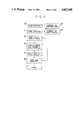
- FIG. 2is a functional block diagram showing a first embodiment of software in a display apparatus of the present invention
- FIGS. 3a-3care flow charts showing operations of a microcomputer in the first embodiment
- FIG. 4is a diagram for explaining operations of a counter which is used in the first embodiment
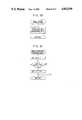
- FIG. 5is a functional block diagram showing a second embodiment of softwares in a display apparatus of the present invention.
- FIG. 6is a flow chart showing operation of a microcomputer in the second embodiment
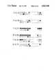
- FIGS. 7a-7fare explanatory representations of display rows of the display apparatus in the second embodiment in operation
- FIG. 8is a functional block diagram showing an arrangement of a touch-type button for recording
- FIG. 9is a schematic diagram showing a structure of the touch-type button shown in FIG. 8.
- FIGS. 10a-10bare flow charts showing operations of a microcomputer of the touch-type button.
- FIG. 11is an explanatory representation of display rows of a further display apparatus that can be used in the invention.
- numeral 11refers to a tape cassette which is loaded in a cassette chamber of a recording and/or playback device.
- a mechanism for driving either of the supply or winding reels of the tape cassette 11is provided with a reel pulse detector 12 for producing a pulse signal in proportion to the number of revolutions of the driving reel.
- the reel pulse detector 12comprises a disc 13 disposed on a rotary shaft of the reel driving mechanism. On the peripheral surface of disc 13 an alternate black and white pattern is formed.
- a photoelectric transducer 14is disposed adjacent the peripheral edge surface of the disc 13 for generating a pulse signal by detecting light reflected by the black and white pattern on such surface. An electrical signal from the photoelectric transducer 14 is transformed to a pulse signal by a reel pulse detecting circuit 15 and then given applied to a central processing unit (CPU) 16 of a microcomputer.
- CPUcentral processing unit
- a magnetic head 17 for a two channel recording and/or playback deviceis to record and reproduce oral statements, on a first track of a magnetic tape, and to record and reproduce a cue mark signal on a second track of the tape which indicates a start position of a dictated item.
- a cue mark signal recorded on the magnetic tapeis read as an electric signal by the magnetic head 17 and applied to CPU 16 via a mark signal detecting circuit 18.
- the CPU 16processes pulse signals from the reel pulse detecting circuit 15 and cue mark signals from the mark signal detecting circuit 18 in accordance with a program which will be described later and the resulting data are stored in a random access memory (RAM), not shown.
- RAMrandom access memory
- ROMread only memory
- the position of the cue mark signal and the present position of a magnetic tapeare displayed respectively on display row means 19, 20.
- the CPU 16is constructed such that, when cue mark signals are detected, the position of a mark signal is converted to a time value by a conversion means on the assumption that the present position of the magnetic tape is the beginning position of the tape (this will not usually be the case) and the results are repeatedly displayed on the display row for displaying a mark signal in the display means (19, 20) at a given time interval.
- references to the beginning of the tapeindicates the beginning of the tape during a playback operation when material recorded on the tape is played back and, typically, transcribed.
- the display row means 19, 20each include a plurality of display segments 19a, 20a arranged in a row for respectively displaying positions of cue mark signals and the present position of the magnetic tape.
- the display row means 19, 20may employ a display apparatus comprising a plurality of display elements such as liquid crystal displays (LCD) and light emitting diodes (LED).
- LCDliquid crystal displays
- LEDlight emitting diodes
- each rowhas thirty LEDs and each display segment 19a, 20a corresponds to a given time interval of one minute when a 30 minute tape is used and two minutes when a magnetic tape for sixty minutes is used.
- each cue mark signal on a magnetic tapeis detected by a mark detecting means 21 and the number of mark signals is counted by a counting means 22.
- Pulses generated from one of the supply and winding reel shafts (and indication of the present position of the tape)are detected by a pulse detecting means 23 and counted by one counter means out of a group of counter means 24.
- Each counter meanscorresponds to a single cue mark signal.
- the display row 19 which displays the cue mark signal positionsis repeatedly reset by a reset means 25 and the contents of the group of counters 24 are repeatedly converted to a time value by a conversion means 26.
- the converted information(time value) is repeatedly displayed on a display means 27 as if the present position of the magnetic tape is the beginning of the tape actual beginning until the end of the magnetic tape is detected by a tape end detecting means 28.
- the relative position of the cue mark signalsare constantly renewed and are revised and displayed to a more correct value as the scanning operation continues.
- FIGS. 3a-3cWhen a tape cassette in which oral statements items have been recorded is loaded into a transcription playback device and rewound, a scanning operation takes place in which the cue mark signals are detected and the reel pulses are counted.
- the address A in a memoryis set equal to "1" (FIG. 3a).
- the address Aidentifies the set of counters to which the reel pulses are to be applied and corresponds to the particular item on the tape identified by a particular cue mark signal.) If the magnetic tape is not at its end before playback, the numerical value in A is applied to a register Y and the display on the display row 19 is reset.
- a calculation for positional correction of counters B (A) assigned by the address Ais effected to calculate the position of the cue mark signal from relative to the presumed beginning of the tape (i.e., the present position of the tape) and the calculated result is displayed on the display row 19.
- the count in register Yis reduced by 1 and the operation is resumed from the newest value.
- the address Aincreases by 1 and all counters B (A) assigned by the address A count up as a function of the reel pulses. Then, the position of a cue mark signal is converted to a time value as a function of the numeral value in the counters B (A) so as to indicate a more proper relative position of the cue mark position as the beginning position of the magnetic tape approaches.
- the scanning operationcan start from any position on a magnetic tape, so that there is no need to wind a cassette tape on which oral statements have been recorded to its end and the operation is conveniently simplified.
- the relative position of a cue mark signalcan be forecast with a transcription playback device as long as a cue mark signal is recorded at the end of an oral statement. This means that the length of the oral statement can be determined before the magnetic tape reaches its beginning, and a typing plan, for example, can be conveniently determined.
- pulsescan be detected from either one of the supply and winding reels, so that it is possible to simplify the present structure and reduce its cost.
- FIG. 5which shows a second embodiment of software in a display apparatus of the present invention
- a specific mark signal recorded on a magnetic tapeis detected by a mark signal detecting means 21 and the number of mark signals is counted by a mark signal counting means 22.
- pulse signals produced by a shaft for driving a recording medium rotatesare detected by a pulse detecting means 23.
- the number of specific mark signalsis counted by a counting means 24 in a group of counters.
- the number of pulsesis counted by a present position counter means 29.
- contents in the present position counter means 29are converted to time by a time converter means 30 for a present position and a position of the next mark signal to the present position is detected by a detector means 31 to be converted to time by a time converter means 32 for mark signals.
- the difference between times of the present position of the recording medium and the next mark signal positionis calculated by a calculator means 33.
- display rows in which a plurality of display segments are arranged in correspondence with a predetermined time periodare set to display in normal resolution by a display setter means 34.
- the display rowsare set to bar-graph display by a bar-graph display setter means 35 so as to be in high resolution.
- the CPU 16processes pulse signals from the reel pulse detecting circuit 15 and cue mark signals from a mark signal detecting circuit 18 in accordance with a program which will be described later and the resulted data are stored in random access memory (RAM), not shown.
- RAMrandom access memory
- the dataare transferred between the RAM and a read-only-memory (ROM), not shown, and the position of a cue mark signal and the present position of a magnetic tape are displayed on the display row means 19, 20, respectively.
- the display means 19, 20are shifted from a normal display to a high resolution display.
- the arrangement of the display row means 19, 20are the same as in the first embodiment.
- the CPU 16processes pulse signals delivered by the reel pulse detecting circuit 15 to record contents of the present position counter for a magnetic tape in an accumulator.
- the contents of the present position counterare converted to time starting from the magnetic winding and the result is stored in a memory.
- contents in a counter for the next cue mark signal position to the present positionare stored in an accumulator and converted to time starting from the magnetic tape winding.
- the display row means 19, 20are set in the normal display and when the difference in time is less than one minute, the display of cue mark signals in the display row means 19, 20 is set to the bar-graph display of high resolution. Subsequently, if the device is in the playback condition, the above-mentioned operations are repeated, and if not, the display row means 19, 20 are set to the normal display to stop the operations.
- data from the reel pulse detecting circuit 15 and the mark signal detecting circuit 18are processed by the CPU 16, and the cue mark position and the present position of a magnetic tape are displayed on the display rows 19, 20, respectively, as shown in FIGS. 7a to 7f.
- cue mark signalsare recorded at a position of 9 to 10 minutes and at a position of 28 to 29 minutes and the magnetic tape is running at a position of 3 to 4 minutes from the actual start position of the tape. Then, the magnetic tape advances to a position of 7 to 8 minutes, as shown in FIG.
- the display row for cue mark signals in the display row means 19, 20are all illuminated to be set to the bar-graph display, as shown in FIG. 7c.
- the entire bar-graph displayrepresents one minute.
- the bar-graphis displayed disabling one or more of lights of the bar-graph so as to indicate the remaining time period, as shown in FIGS. 7d and e.
- the display row for cue mark signalsis reset to the normal display as shown in FIG. 7f.
- the remaining time periodcan be read in units of seconds, so that it is possible to accurately know the remainder in an oral statement.
- judging means 44that determines the button 41 has not been continuously operated for a given time
- the contents stored in the storing means 43are erased by a reset means 46. As such, a desired mode is not set until the button 41 is is continuously operated for a given time.
- FIG. 9shows an example of the foregoing device which is applied to a tape recorder.
- a touch-type button 41 for selecting various modesis for use in recording.
- an electric signalis produced.
- the electric signalis fed to a central processing unit (CPU) 52 of a microcomputer in which the signal is processed in accordance with a program which will be described later.
- CPUcentral processing unit
- the CPU 52allows a storing means, such as a random access memory (RAM), not shown, to store the information that the button 41 has been depressed in response to an electrical signal from the button 41.
- the information contentsare transferred between the RAM and a read-only-memory (ROM), not shown.
- ROMread-only-memory
- An analog IC 53is switched by a recording mode setting signal of the CPU 52 to the recording mode. With the recording mode thus switched, information from a microphone 54 is recorded through a magnetic head 55 on a magnetic recording medium.
- buttonsfor various modes of playback, stop, rewinding, quick transporting, or the like may be employed. These buttons may be controlled by the CPU 52 to set corresponding modes when they are continuously operated for a given time.
- a playback modeis set, information recorded on a magnetic recording medium is read by a magnetic head 55 and then is reproduced, through the analog IC 53, on a speaker 56 as sound.
- the button 41 for a desired mode(FIG. 9) is operable by continuously depressing for a given short time, so that it is possible to quickly set a desired mode and to rapidly start recording information when desired, with easy operation of the button.
- the displayhas three rows: E, an end mark position display row which indicates the end of (each item (e.g., letter); P, a tape present position display row which indicates a present position of a tape as it is running; and I, an instruction mark position display row which indicates instructions to oral statements, order of typing and the like.
- respective segments constituting the rowsare varied in size and color in order to facilitate identification for display.
- the P display rowis disposed in the center and is in green
- the I and E display rowsare respectively disposed the upper and lower sides of the P display row and their segments are larger than that of the P display row in size and are in red.
Landscapes
- Indexing, Searching, Synchronizing, And The Amount Of Synchronization Travel Of Record Carriers (AREA)
Abstract
Description
Claims (13)
Applications Claiming Priority (6)
| Application Number | Priority Date | Filing Date | Title |
|---|---|---|---|
| JP61-144242 | 1986-06-20 | ||
| JP61-144241 | 1986-06-20 | ||
| JP14424286AJPS63885A (en) | 1986-06-20 | 1986-06-20 | Display device |
| JP14424186AJPS63884A (en) | 1986-06-20 | 1986-06-20 | Position display device for mark signal |
| JP61144243AJPS63845A (en) | 1986-06-20 | 1986-06-20 | Recording and reproducing device |
| JP61-144243 | 1986-06-20 |
Publications (1)
| Publication Number | Publication Date |
|---|---|
| US4812940Atrue US4812940A (en) | 1989-03-14 |
Family
ID=27318790
Family Applications (1)
| Application Number | Title | Priority Date | Filing Date |
|---|---|---|---|
| US07/062,868Expired - Fee RelatedUS4812940A (en) | 1986-06-20 | 1987-06-16 | Dictation display for displaying present position and cue mark position information |
Country Status (2)
| Country | Link |
|---|---|
| US (1) | US4812940A (en) |
| DE (1) | DE3720433A1 (en) |
Cited By (24)
| Publication number | Priority date | Publication date | Assignee | Title |
|---|---|---|---|---|
| US5375025A (en)* | 1989-05-03 | 1994-12-20 | Samsung Electronics Co., Ltd. | Method of measuring the remaining time of tape in a tape recorder |
| US5434370A (en)* | 1993-11-05 | 1995-07-18 | Microfield Graphics, Inc. | Marking system with pen-up/pen-down tracking |
| US5479268A (en)* | 1990-09-10 | 1995-12-26 | Starsight Telecast Inc. | User interface for television schedule system |
| US5583323A (en)* | 1993-11-05 | 1996-12-10 | Microfield Graphics, Inc. | Calibration of graphic data-acquisition tracking system |
| US5585605A (en)* | 1993-11-05 | 1996-12-17 | Microfield Graphics, Inc. | Optical-scanning system employing laser and laser safety control |
| US5684506A (en)* | 1995-09-20 | 1997-11-04 | Sharper Image Corporation | Digital recorder apparatus with graphical display representation and method |
| US5832173A (en)* | 1991-11-28 | 1998-11-03 | Sony Corporation | Apparatus for reproducing a video signal recorded on tape and for searching the tape |
| US5956298A (en)* | 1997-11-10 | 1999-09-21 | Gough; Jesse Lynn | Voice prompting and indexing dictation recorder |
| US20020054068A1 (en)* | 2000-03-31 | 2002-05-09 | United Video Properties, Inc. | Systems and methods for reducing cut-offs in program recording |
| US20040085291A1 (en)* | 2002-08-23 | 2004-05-06 | Youichi Yamada | Information processing unit, display method for the information processing unit, program for the same, recording medium for recording the program therein and reproducing unit |
| US6832385B2 (en) | 1990-09-10 | 2004-12-14 | United Video Properties, Inc. | Television schedule system |
| US20050058433A1 (en)* | 1989-10-30 | 2005-03-17 | Patrick Young | Television schedule system |
| US20050204388A1 (en)* | 1998-06-11 | 2005-09-15 | Knudson Edward B. | Series reminders and series recording from an interactive television program guide |
| US20050251828A1 (en)* | 1989-10-30 | 2005-11-10 | Starsight Telecast, Inc. | Television schedule system |
| US20050264793A1 (en)* | 2004-04-30 | 2005-12-01 | Jurgen Roders | Method for measuring a tool of a machine tool |
| US20100325668A1 (en)* | 1998-08-11 | 2010-12-23 | Starsight Telecast, Inc. | Television schedule system |
| US8291461B2 (en) | 2000-10-11 | 2012-10-16 | United Video Properties, Inc. | Systems and methods for managing the distribution of on-demand media |
| US8407737B1 (en) | 2007-07-11 | 2013-03-26 | Rovi Guides, Inc. | Systems and methods for providing a scan transport bar |
| US8799954B1 (en) | 2006-07-31 | 2014-08-05 | Rovi Guides, Inc. | Systems and methods for providing custom media content flipping |
| US8806533B1 (en) | 2004-10-08 | 2014-08-12 | United Video Properties, Inc. | System and method for using television information codes |
| US8989561B1 (en) | 2008-05-29 | 2015-03-24 | Rovi Guides, Inc. | Systems and methods for alerting users of the postponed recording of programs |
| US9038103B2 (en) | 2005-05-06 | 2015-05-19 | Rovi Guides, Inc. | Systems and methods for content surfing |
| US9185332B2 (en) | 2005-05-06 | 2015-11-10 | Rovi Guides, Inc. | Systems and methods for providing a scan |
| US9848161B2 (en) | 2003-04-21 | 2017-12-19 | Rovi Guides, Inc. | Video recorder having user extended and automatically extended time slots |
Families Citing this family (2)
| Publication number | Priority date | Publication date | Assignee | Title |
|---|---|---|---|---|
| JPH02192089A (en)* | 1988-10-04 | 1990-07-27 | Asahi Optical Co Ltd | electronic still camera |
| JPH0297183A (en)* | 1988-10-04 | 1990-04-09 | Asahi Optical Co Ltd | electronic still camera |
Citations (10)
| Publication number | Priority date | Publication date | Assignee | Title |
|---|---|---|---|---|
| JPS54143220A (en)* | 1978-04-18 | 1979-11-08 | Assmann Gmbh | Special information* mark or instruction position indicator on recording carrier |
| JPS5552573A (en)* | 1978-10-13 | 1980-04-17 | Sanyo Electric Co Ltd | Tape recorder |
| US4200893A (en)* | 1978-05-17 | 1980-04-29 | Dictaphone Corporation | Instruction indicating apparatus for a record and/or playback device |
| JPS57141084A (en)* | 1981-02-25 | 1982-09-01 | Pioneer Electronic Corp | System for measuring recording time |
| JPS5834634A (en)* | 1981-08-24 | 1983-03-01 | Nec Corp | Service channel transmitting system in time division multi-way multiplex communication system |
| JPS5841457A (en)* | 1981-09-01 | 1983-03-10 | Victor Co Of Japan Ltd | Tape recorder |
| US4386379A (en)* | 1980-10-10 | 1983-05-31 | Sony Corporation | Videotape cue control and display apparatus |
| US4398279A (en)* | 1981-05-04 | 1983-08-09 | Lanier Business Products, Inc. | Digital display for dictation transcriber for indicating remaining tape within discrete segments of dictation |
| US4399527A (en)* | 1979-04-09 | 1983-08-16 | Lanier Business Products, Inc. | Dictation display device |
| US4410923A (en)* | 1981-01-09 | 1983-10-18 | Dictaphone Corporation | Display apparatus for recording and/or playback device |
Family Cites Families (5)
| Publication number | Priority date | Publication date | Assignee | Title |
|---|---|---|---|---|
| DE2650665C3 (en)* | 1976-11-05 | 1979-07-05 | Grundig E.M.V. Elektro-Mechanische Versuchsanstalt Max Grundig, 8510 Fuerth | Method and device for determining the elapsed playing time or tape length and / or the remaining time of cassettes or reels of tape-shaped information carriers |
| US4352173A (en)* | 1979-04-09 | 1982-09-28 | Lanier Business Products, Inc. | Dictation display device |
| US4686587A (en)* | 1983-12-21 | 1987-08-11 | Dictaphone Corporation | Record and/or playback device with cue signal indication and access |
| US4688117A (en)* | 1983-12-21 | 1987-08-18 | Dictaphone Corporation | Display including variable mode for a record and/or playback device |
| JP2537166B2 (en)* | 1984-04-28 | 1996-09-25 | キヤノン株式会社 | Recording or playback device |
- 1987
- 1987-06-16USUS07/062,868patent/US4812940A/ennot_activeExpired - Fee Related
- 1987-06-19DEDE19873720433patent/DE3720433A1/enactiveGranted
Patent Citations (10)
| Publication number | Priority date | Publication date | Assignee | Title |
|---|---|---|---|---|
| JPS54143220A (en)* | 1978-04-18 | 1979-11-08 | Assmann Gmbh | Special information* mark or instruction position indicator on recording carrier |
| US4200893A (en)* | 1978-05-17 | 1980-04-29 | Dictaphone Corporation | Instruction indicating apparatus for a record and/or playback device |
| JPS5552573A (en)* | 1978-10-13 | 1980-04-17 | Sanyo Electric Co Ltd | Tape recorder |
| US4399527A (en)* | 1979-04-09 | 1983-08-16 | Lanier Business Products, Inc. | Dictation display device |
| US4386379A (en)* | 1980-10-10 | 1983-05-31 | Sony Corporation | Videotape cue control and display apparatus |
| US4410923A (en)* | 1981-01-09 | 1983-10-18 | Dictaphone Corporation | Display apparatus for recording and/or playback device |
| JPS57141084A (en)* | 1981-02-25 | 1982-09-01 | Pioneer Electronic Corp | System for measuring recording time |
| US4398279A (en)* | 1981-05-04 | 1983-08-09 | Lanier Business Products, Inc. | Digital display for dictation transcriber for indicating remaining tape within discrete segments of dictation |
| JPS5834634A (en)* | 1981-08-24 | 1983-03-01 | Nec Corp | Service channel transmitting system in time division multi-way multiplex communication system |
| JPS5841457A (en)* | 1981-09-01 | 1983-03-10 | Victor Co Of Japan Ltd | Tape recorder |
Cited By (60)
| Publication number | Priority date | Publication date | Assignee | Title |
|---|---|---|---|---|
| US5375025A (en)* | 1989-05-03 | 1994-12-20 | Samsung Electronics Co., Ltd. | Method of measuring the remaining time of tape in a tape recorder |
| US20050251828A1 (en)* | 1989-10-30 | 2005-11-10 | Starsight Telecast, Inc. | Television schedule system |
| US20050058433A1 (en)* | 1989-10-30 | 2005-03-17 | Patrick Young | Television schedule system |
| US7748018B2 (en) | 1989-10-30 | 2010-06-29 | Starsight Telecast, Inc. | Arranging channel indicators in a television schedule system |
| US6832385B2 (en) | 1990-09-10 | 2004-12-14 | United Video Properties, Inc. | Television schedule system |
| US20040008971A1 (en)* | 1990-09-10 | 2004-01-15 | Starsight Telecast, Inc. | User interface for television schedule system |
| US7187847B2 (en) | 1990-09-10 | 2007-03-06 | Starsight Telecast, Inc. | User interface for television schedule system |
| US7209640B2 (en) | 1990-09-10 | 2007-04-24 | Starsight Telecast, Inc. | User interface for television schedule system |
| US20050251836A1 (en)* | 1990-09-10 | 2005-11-10 | Starsight Telecast Inc. | User interface for television schedule system |
| US5949954A (en)* | 1990-09-10 | 1999-09-07 | Starsight Telecast, Inc. | System and process for control of recording and reproducing apparatus |
| US8087046B2 (en) | 1990-09-10 | 2011-12-27 | Starsight Telecast, Inc. | User interface for television schedule system |
| US6167188A (en)* | 1990-09-10 | 2000-12-26 | Starsight Telecast, Inc. | User interface for television schedule system |
| US8069460B2 (en) | 1990-09-10 | 2011-11-29 | Starsight Telecast, Inc. | User interface for television schedule system |
| US6498895B2 (en) | 1990-09-10 | 2002-12-24 | Starsight Telecast, Inc. | User interface for television schedule system |
| US20080098431A1 (en)* | 1990-09-10 | 2008-04-24 | Starsight Telecast Inc. | User interface for television schedule system |
| US5479268A (en)* | 1990-09-10 | 1995-12-26 | Starsight Telecast Inc. | User interface for television schedule system |
| US20050044567A1 (en)* | 1990-09-10 | 2005-02-24 | Starsight Telecast Inc. | User interface for television schedule system |
| US7477832B2 (en) | 1990-09-10 | 2009-01-13 | Starsight Telecast Inc. | User interface for television schedule system |
| US7151886B2 (en) | 1990-09-10 | 2006-12-19 | Starsight Telecast Inc. | User interface for television schedule system |
| US5832173A (en)* | 1991-11-28 | 1998-11-03 | Sony Corporation | Apparatus for reproducing a video signal recorded on tape and for searching the tape |
| US5583323A (en)* | 1993-11-05 | 1996-12-10 | Microfield Graphics, Inc. | Calibration of graphic data-acquisition tracking system |
| US5623129A (en)* | 1993-11-05 | 1997-04-22 | Microfield Graphics, Inc. | Code-based, electromagnetic-field-responsive graphic data-acquisition system |
| US5585605A (en)* | 1993-11-05 | 1996-12-17 | Microfield Graphics, Inc. | Optical-scanning system employing laser and laser safety control |
| US5434370A (en)* | 1993-11-05 | 1995-07-18 | Microfield Graphics, Inc. | Marking system with pen-up/pen-down tracking |
| US5665942A (en)* | 1993-11-05 | 1997-09-09 | Microfield Graphics, Inc. (Softboard, Inc.) | Optical-scanning system employing laser and laser safety control |
| US5684506A (en)* | 1995-09-20 | 1997-11-04 | Sharper Image Corporation | Digital recorder apparatus with graphical display representation and method |
| USRE38080E1 (en)* | 1997-11-10 | 2003-04-15 | Jesse Lynn Gough | Voice prompting and indexing dictation recorder |
| US5956298A (en)* | 1997-11-10 | 1999-09-21 | Gough; Jesse Lynn | Voice prompting and indexing dictation recorder |
| US8555321B2 (en) | 1998-06-11 | 2013-10-08 | United Video Properties, Inc. | Series reminders and series recording from an interactive program guide |
| US9043844B2 (en) | 1998-06-11 | 2015-05-26 | Rovi Guides, Inc. | Series reminders and series recording from an interactive television program guide |
| US20080184313A1 (en)* | 1998-06-11 | 2008-07-31 | Knudson Edward B | Series reminders and series recording from an interactive program guide |
| US9521461B2 (en) | 1998-06-11 | 2016-12-13 | Rovi Guides, Inc. | Series reminders and series recording from an interactive television program guide |
| US9426533B2 (en) | 1998-06-11 | 2016-08-23 | Rovi Guides, Inc. | Series reminders and series recording from an interactive television program guide |
| US8522287B2 (en) | 1998-06-11 | 2013-08-27 | United Video Properties, Inc. | Series reminders and series recording from an interactive program guide |
| US9032445B2 (en) | 1998-06-11 | 2015-05-12 | Rovi Guides, Inc. | Series reminders and series recording from an interactive television program guide |
| US20100287590A1 (en)* | 1998-06-11 | 2010-11-11 | United Video Properties, Inc. | Series reminders and series recording from an interactive program guide |
| US8745669B2 (en) | 1998-06-11 | 2014-06-03 | United Video Properties, Inc. | Series reminders and series recording from an interactive program guide |
| US20050204388A1 (en)* | 1998-06-11 | 2005-09-15 | Knudson Edward B. | Series reminders and series recording from an interactive television program guide |
| US8464296B2 (en) | 1998-06-11 | 2013-06-11 | United Video Properties, Inc. | Series reminders and series recording from an interactive program guide |
| US20100325668A1 (en)* | 1998-08-11 | 2010-12-23 | Starsight Telecast, Inc. | Television schedule system |
| US20100150528A1 (en)* | 2000-03-31 | 2010-06-17 | United Video Properties, Inc. | Systems and methods for reducing cut-offs in program recording |
| US20020054068A1 (en)* | 2000-03-31 | 2002-05-09 | United Video Properties, Inc. | Systems and methods for reducing cut-offs in program recording |
| US20100215341A1 (en)* | 2000-03-31 | 2010-08-26 | United Video Properties, Inc. | Systems and methods for reducing cut-offs in program recording |
| US9307278B2 (en) | 2000-03-31 | 2016-04-05 | Rovi Guides, Inc. | Systems and methods for reducing cut-offs in program recording |
| US9197916B2 (en) | 2000-10-11 | 2015-11-24 | Rovi Guides, Inc. | Systems and methods for communicating and enforcing viewing and recording limits for media-on-demand |
| US8291461B2 (en) | 2000-10-11 | 2012-10-16 | United Video Properties, Inc. | Systems and methods for managing the distribution of on-demand media |
| US7115807B2 (en) | 2002-08-23 | 2006-10-03 | Pioneer Corporation | Information processing unit, display method for the information processing unit, program for the same, recording medium for recording the program therein and reproducing unit |
| EP1394791A3 (en)* | 2002-08-23 | 2004-11-24 | Pioneer Corporation | Displaying an instructed position of a recording medium, defined by information processing unit, display method, program, recording medium and reproducing unit |
| US20040085291A1 (en)* | 2002-08-23 | 2004-05-06 | Youichi Yamada | Information processing unit, display method for the information processing unit, program for the same, recording medium for recording the program therein and reproducing unit |
| US9848161B2 (en) | 2003-04-21 | 2017-12-19 | Rovi Guides, Inc. | Video recorder having user extended and automatically extended time slots |
| US20050264793A1 (en)* | 2004-04-30 | 2005-12-01 | Jurgen Roders | Method for measuring a tool of a machine tool |
| US8806533B1 (en) | 2004-10-08 | 2014-08-12 | United Video Properties, Inc. | System and method for using television information codes |
| US9038103B2 (en) | 2005-05-06 | 2015-05-19 | Rovi Guides, Inc. | Systems and methods for content surfing |
| US9185332B2 (en) | 2005-05-06 | 2015-11-10 | Rovi Guides, Inc. | Systems and methods for providing a scan |
| US8799954B1 (en) | 2006-07-31 | 2014-08-05 | Rovi Guides, Inc. | Systems and methods for providing custom media content flipping |
| US8407737B1 (en) | 2007-07-11 | 2013-03-26 | Rovi Guides, Inc. | Systems and methods for providing a scan transport bar |
| US9723363B2 (en) | 2008-05-29 | 2017-08-01 | Rovi Guides, Inc. | Systems and methods for alerting users of the postponed recording of programs |
| US8989561B1 (en) | 2008-05-29 | 2015-03-24 | Rovi Guides, Inc. | Systems and methods for alerting users of the postponed recording of programs |
| US11245965B2 (en) | 2008-05-29 | 2022-02-08 | Rovi Guides, Inc. | Systems and methods for alerting users of the postponed recording of programs |
| US11689768B2 (en) | 2008-05-29 | 2023-06-27 | Rovi Guides, Inc. | Systems and methods for alerting users of the postponed recording of programs |
Also Published As
| Publication number | Publication date |
|---|---|
| DE3720433C2 (en) | 1991-02-14 |
| DE3720433A1 (en) | 1987-12-23 |
Similar Documents
| Publication | Publication Date | Title |
|---|---|---|
| US4812940A (en) | Dictation display for displaying present position and cue mark position information | |
| CA1149934A (en) | Magnetic tape recorder having a tape drive controller implemented with a digital processor chip | |
| US3921220A (en) | Apparatus for automatic high speed positioning of magnetic recording tape by sensing reel revolutions from tape beginning | |
| GB2170037A (en) | Method and apparatus for displaying indications of instructions in previously recorded messages | |
| US4224644A (en) | Method and apparatus for controlling a tape player/recorder for retrieving and playing prerecorded information | |
| US4200893A (en) | Instruction indicating apparatus for a record and/or playback device | |
| JP2006526958A5 (en) | ||
| US4410923A (en) | Display apparatus for recording and/or playback device | |
| CA1276720C (en) | Display including variable mode | |
| EP0064674B1 (en) | Digital display for dictation transcriber | |
| US4365326A (en) | Record player | |
| US4228470A (en) | Electronic reminder system | |
| GB2154043A (en) | Record and/or playback device | |
| US5032937A (en) | Magnetic tape recording and/or reproducing apparatus having automatic mode changing capabilities | |
| US4363039A (en) | Automatic operation control apparatus for a PCM recording and reproducing system | |
| GB2157054A (en) | Tape recorders | |
| JPS63884A (en) | Position display device for mark signal | |
| JPS5813991B2 (en) | Tape counter devices such as tape recorders | |
| US5126888A (en) | System for recording and detecting marking signals | |
| USRE35032E (en) | Electronic reminder system | |
| JP2619887B2 (en) | Magnetic tape playback device | |
| US4858213A (en) | Display for modular dictation/transcription system | |
| JPS6224363Y2 (en) | ||
| JP2769250B2 (en) | Magnetic tape playback device | |
| KR0129151B1 (en) | How to determine the thickness of your video tape |
Legal Events
| Date | Code | Title | Description |
|---|---|---|---|
| AS | Assignment | Owner name:OLYMPUS OPTICAL COMPANY LTD., 43-2, 2-CHOME, HATAG Free format text:ASSIGNMENT OF ASSIGNORS INTEREST.;ASSIGNOR:TAKENAGA, HIDEO;REEL/FRAME:004728/0871 Effective date:19870520 Owner name:OLYMPUS OPTICAL COMPANY LTD., A CORP. OF JAPAN,JAP Free format text:ASSIGNMENT OF ASSIGNORS INTEREST;ASSIGNOR:TAKENAGA, HIDEO;REEL/FRAME:004728/0871 Effective date:19870520 | |
| FEPP | Fee payment procedure | Free format text:PAYOR NUMBER ASSIGNED (ORIGINAL EVENT CODE: ASPN); ENTITY STATUS OF PATENT OWNER: LARGE ENTITY | |
| FPAY | Fee payment | Year of fee payment:4 | |
| FEPP | Fee payment procedure | Free format text:PAYOR NUMBER ASSIGNED (ORIGINAL EVENT CODE: ASPN); ENTITY STATUS OF PATENT OWNER: LARGE ENTITY Free format text:PAYER NUMBER DE-ASSIGNED (ORIGINAL EVENT CODE: RMPN); ENTITY STATUS OF PATENT OWNER: LARGE ENTITY | |
| FPAY | Fee payment | Year of fee payment:8 | |
| REMI | Maintenance fee reminder mailed | ||
| LAPS | Lapse for failure to pay maintenance fees | ||
| FP | Lapsed due to failure to pay maintenance fee | Effective date:20010314 | |
| STCH | Information on status: patent discontinuation | Free format text:PATENT EXPIRED DUE TO NONPAYMENT OF MAINTENANCE FEES UNDER 37 CFR 1.362 |