US4812909A - Cell classification apparatus capable of displaying a scene obtained by superimposing a character scene and graphic scene on a CRT - Google Patents
Cell classification apparatus capable of displaying a scene obtained by superimposing a character scene and graphic scene on a CRTDownload PDFInfo
- Publication number
- US4812909A US4812909AUS07/079,959US7995987AUS4812909AUS 4812909 AUS4812909 AUS 4812909AUS 7995987 AUS7995987 AUS 7995987AUS 4812909 AUS4812909 AUS 4812909A
- Authority
- US
- United States
- Prior art keywords
- scene
- image
- video
- character
- sample
- Prior art date
- Legal status (The legal status is an assumption and is not a legal conclusion. Google has not performed a legal analysis and makes no representation as to the accuracy of the status listed.)
- Expired - Fee Related
Links
- 230000015654memoryEffects0.000claimsabstractdescription7
- 210000000601blood cellAnatomy0.000claimsdescription12
- 210000004369bloodAnatomy0.000claimsdescription9
- 239000008280bloodSubstances0.000claimsdescription9
- 230000004044responseEffects0.000claimsdescription5
- 239000003086colorantSubstances0.000claimsdescription3
- 230000001276controlling effectEffects0.000claims1
- 230000002596correlated effectEffects0.000claims1
- 239000000872bufferSubstances0.000description4
- 235000019557luminanceNutrition0.000description4
- 230000004048modificationEffects0.000description4
- 238000012986modificationMethods0.000description4
- 238000010586diagramMethods0.000description3
- 230000008859changeEffects0.000description2
- 210000003743erythrocyteAnatomy0.000description1
- 210000000265leukocyteAnatomy0.000description1
- 238000000034methodMethods0.000description1
- 230000009466transformationEffects0.000description1
Images


Classifications
- H—ELECTRICITY
- H04—ELECTRIC COMMUNICATION TECHNIQUE
- H04N—PICTORIAL COMMUNICATION, e.g. TELEVISION
- H04N5/00—Details of television systems
- H04N5/222—Studio circuitry; Studio devices; Studio equipment
- H04N5/262—Studio circuits, e.g. for mixing, switching-over, change of character of image, other special effects ; Cameras specially adapted for the electronic generation of special effects
- H04N5/278—Subtitling
Definitions
- This inventionrelates to an image display apparatus, and more particularly to an apparatus of the kind above described which is suitable for application to, for example, an apparatus for automated classification of blood cells so as to simultaneously display two or more different scenes such as a picture scene displaying an image of a blood sample and a character scene displaying data regarding the blood sample, so that an operator can observe the combined scenes on a single CRT.
- a prior art apparatus for automated classification of blood cellsis disclosed in U.S. Pat. No. 4,175,859.
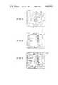
- an operatorrequired to observe not only a picture scene 1 displaying, for example, the state of a blood sample containing white blood cells 3 and red blood cells 4 as shown in FIG. 1a, but also a character scene 2 displaying data regarding the blood sample as shown in FIG. 1b.
- the manner of change-over between these scenesis disclosed in a catalog of "Hitachi's 806 Type Apparatus for Automated Classification of Blood Cells" published by Hitachi Ltd.
- the above object of the present inventionis attained by merely electrically adding a plurality of video signals by an adder.
- This inventionis based on the fact that the inventors have found that, even when a picture scene 1 as shown in FIG. 1a and a character scene 2 as shown in FIG. 1b are displayed in a superposed relation as shown by a scene 100 in FIG. 2, the sample image displayed in the picture scene can be sufficiently clearly identified without being appreciably affected by the characters displayed in the character scene, and the characters displayed in the character scene can also be sufficiently clearly read.
- FIGS. 1a and 1bshow examples of a picture scene and a character scene displayed in an automated blood-cell classification apparatus, respectively.
- FIG. 2shows an example of a combination scene displayed according to the present invention.
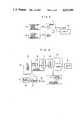
- FIG. 3illustrates the basic principle of the present invention.
- FIG. 4is a block diagram showing the structure of an embodiment of the present invention.
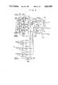
- FIG. 5is a circuit diagram showing in detail the structure of part of the embodiment shown in FIG. 4.
- FIG. 6shows schematically the structure of a modification of part of the embodiment of the present invention when analog video signals are applied as inputs.
- FIG. 7shows schematically the structure of another modification of part of the embodiment of the present invention when digital video signals are applied as inputs.
- FIG. 8shows schematically the structure of another modification of part of the embodiment of the present invention when three or more video signals are applied as inputs.
- FIG. 9shows schematically the structure of another modification of part of the embodiment of the present invention, in which the luminance of each of video input signals is made adjustable.
- FIG. 3illustrates the basic principle of image display according to the present invention.
- a character-scene signal generator 5generates a video signal S 1 representing a character scene (for example, that shown in FIG. 1b) for displaying data regarding a sample being measured
- a picture-scene signal generator 6generates a video signal S 2 representing a picture scene (for example, that shown in FIG. 1a) for displaying an image of the sample.
- These video signals S 1 and S 2are applied to an adder 7.
- the video signals S 1 and S 2are added to each other after being multiplied by weights a 1 and a 2 respectively.
- the value of the weight associated with that sceneis increased.
- the video signal S 1is displayed with a density larger than that of the video signal S 2 .
- FIG. 4shows an automated blood-cell classification apparatus to which the present invention is applied.
- like reference numeralsare used to designate like parts appearing in FIG. 3.
- a TV camera image of a blood sample 16 including blood cells being classified(a picture scene 1 as shown in FIG. 1a) and a character scene displaying data regarding the blood cells being classified (a character scene 2 as shown in FIG. 1b) are simultaneously displayed on a color CRT 8 as a single scene 100 as shown in FIG. 2.
- reference numerals 5, 6 and 12designate a character-scene signal generator, a blood-cell picture-scene signal generator and a video signal synthesizer, respectively.
- the character-scene signal generator 5is composed of a computer system 9, a CRT controller 10, an address buffer 11 and a memory 13.
- the picture-scene signal generator 6is composed of a TV camera 17 picking up an image of a blood sample 16.
- the video signal synthesizer 12is composed of an adder 7 and a video signal buffer 14.
- a video signal S 1 representing a character sceneis applied from the memory 13 to the adder 7, and a video signal S 2 representing a picture scene is applied from the TV camera 17 to the adder 7 through the video signal buffer 14.
- These signals S 1 and S 2are added to each other by the adder 7, and the resultant sum signal is applied to the color CRT 8 which is the display device displaying both the character data and the blood cell image in an overlapping relation.
- FIG. 5is a circuit diagram showing in detail the structure of the video signal synthesizer 12.
- memories 18-1, 18-2 and 18-3(of, for example, Model HM6116) corresponding to red (R), green (G) and blue (B), which are three primary colors, respectively store character information, and, in response to the application of a write clock signal CLOCK-1, 8-bit parallel data from the memories 18-1, 18-2 and 18-3 are loaded in corresponding ones respectively of shift registers 19-1 19-2 and 19-3 (of, for example, Model 74116). In response to the application of a shift clock signal, the 8-bit parallel data loaded in the individual shift registers 19-1, 19-2 and 19-3 are read out one bit by one bit at a high speed.
- a write clock signal CLOCK-18-bit parallel data from the memories 18-1, 18-2 and 18-3 are loaded in corresponding ones respectively of shift registers 19-1 19-2 and 19-3 (of, for example, Model 74116).
- shift registers 19-1, 19-2 and 19-3are read out one bit by one bit at a high speed.
- the data bits read out from these shift registers 19-1, 19-2 and 19-3are applied to associated inverters (which are, for example, NAND gates of Model 75451) and associated transistors to appear as a video signal S 1 for displaying a character scene.
- associated inverterswhich are, for example, NAND gates of Model 75451
- associated transistorsto appear as a video signal S 1 for displaying a character scene.
- next 8-bit dataare loaded in the respective shift registers from the associated memories 18-1, 18-2 and 18-3 in response to the application of a write clock signal CLOCK-1.
- the TV camera 17picking up an image of blood cells in a blood sample 16 generates, as its output signal, a video signal S 2 for displaying a picture scene.
- the video signal S 2is disintegrated into signals S R , S G and S B (where the suffixes R, G and B indicate that the signals are color signals of red, green and blue respectively).
- the color signals S R , S G and S Bare subjected to impedance transformation in signal buffers 14-1, 14-2 and 14-3 (of, for example, Model LH0032) respectively.
- the video signals S 1 and S 2are applied through analog switches 20-1, 20-2, 20-3, 20-4, 20-5 and 20-6 (of, for example, Model IH5036) to adders 7-1, 7-2 and 7-3 (of, for example, Model LH0032) corresponding to the three primary colors respectively.
- Output signals from the adders 7-1, 7-2 and 7-3are applied to associated transistors (of, for example, Model 2SC689) to appear as sum video signals D R , D G and D B respectively, and these signals D R , D G and D B are applied to the color CRT 8.
- Output signals of a latch 103are used to selectively turn on and off the analog switches 20-1 to 20-6, so as to selectively display (i) a character scene only (FIG. 1b), (ii) a picture scene only (FIG. 1a), or (iii) an overlapping scene (FIG. 2) of a character scene and a picture scene, on the color CRT 8. That is, a character scene as shown in FIG. 1b is displayed on the color CRT 8 when the output signals of the latch 103 are used to turn on the analog switches 20-1, 20-2 and 20-3 and to turn off the analog switches 20-4, 20-5 and 20-6. On the other hand, a picture scene as shown in FIG.
- the latch 103controls the analog switches 20-1 to 20-6 by latching data from the computer system 9 shown in FIG. 4 in response to the application of a write clock signal CLOCK-2.
- the timing of application of the write clock CLOCK-1, write clock CLOCK-2 and shift clockis determined by the computer system 9 and CRT controller 10 shown in FIG. 4.
- the weights a 1 and a 2(FIG. 3) used for multiplying the video signals S 1 and S 2 respectively will be described, by taking the adder, including an operational amplifier as 7-1 shown in FIG. 5, as an example.
- the weights a 1 and a 2 in this caseare determined by the following equations (1) and (2) respectively:
- R 1 , R 2 and R 3are resistance values of resistors 21-1, 22-1 and 23-1 for the operational amplifier 7-1 respectively.
- the practical numerical values of R 1 , R 2 and R 3are, for example, 2.2 k ⁇ , 2.2 k ⁇ and 1 k ⁇ , respectively so that the weights a 1 and a 2 both take a value, 0.45 as shown in the above equations (1) and (2).
- FIG. 6shows an adder 71 preferably used when both the video signals S 1 and S 2 are analog signals.
- the adder 71includes an operational amplifier as shown.
- FIG. 7shows an adder 72 preferably used when both the video signals S 1 and S 2 are digital signals.
- the sum video signal Dis converted by a D/A converter 81 into an analog signal before being applied to the display device 8.
- FIG. 8shows that video signals S 1 , S 2 . . . , S n generated from a first video signal generator 51, a second video signal generator 52, . . . , and an n-th video signal generator 53 (where n is a positive integer larger than or equal to 3) are applied to an adder 73 so as to superpose three or more scenes in a manner well known in the art.
- the adder 73includes an operational amplifier as shown.
- difficulty of displaying an easily recognizable scene due to overlapping of scenescan be lessened by suitably selecting the color of character information in relation to image information to be displayed.
- FIG. 9shows an adder 74 preferably used to multiply two video signals S 1 and S 2 by suitable weights a 1 and a 2 respectively. It will be apparent from FIG. 9 that the weights a 1 and a 2 are continuously changed by a first variable resistor VR 1 to adjust the relative luminances of a character scene and a picture scene, and the overall luminance of the combined scene is then adjusted by a second variable resistor VR 2 .
- the adder 74includes operational amplifiers as shown.
- a plurality of different scenescan be simultaneously observed.
- a plurality of scenescan be displayed as a single scene without the necessity for provision of a complicated timing circuit. This is readily apparent from the fact that, when a plurality of scenes are to be displayed on a CRT according to, for example, a multi-window method, complicated and troublesome timing control is required so as to change over video signals in synchronism with a horizontal synchronizing signal or to previously prepare data to be displayed in timed relation with the scanning timing of the CRT.
Landscapes
- Engineering & Computer Science (AREA)
- Multimedia (AREA)
- Signal Processing (AREA)
- Studio Circuits (AREA)
- Controls And Circuits For Display Device (AREA)
Abstract
Description
This invention relates to an image display apparatus, and more particularly to an apparatus of the kind above described which is suitable for application to, for example, an apparatus for automated classification of blood cells so as to simultaneously display two or more different scenes such as a picture scene displaying an image of a blood sample and a character scene displaying data regarding the blood sample, so that an operator can observe the combined scenes on a single CRT.
A prior art apparatus for automated classification of blood cells is disclosed in U.S. Pat. No. 4,175,859. In such an apparatus, an operator required to observe not only apicture scene 1 displaying, for example, the state of a blood sample containingwhite blood cells 3 andred blood cells 4 as shown in FIG. 1a, but also acharacter scene 2 displaying data regarding the blood sample as shown in FIG. 1b. It has been a prior art practice that, for the purpose of observation of these plural scenes, an operator manipulates an input keyboard to change over between the scene shown in FIG. 1a and that shown in FIG. 1b. The manner of change-over between these scenes is disclosed in a catalog of "Hitachi's 806 Type Apparatus for Automated Classification of Blood Cells" published by Hitachi Ltd. in March, 1985. However, this prior art apparatus had a drawback that the operator could not simultaneously observe separate scenes. It will be very convenient for an operator of this kind of automated classification (analysis) apparatus when a picture scene displaying an image of a sample and a character scene displaying data regarding the sample can be simultaneously observed by the operator.
It is an object of the present invention to provide an image display system which can display a plurality of different information in an overlapping relation in the same scene in spite of a simple structure.
The above object of the present invention is attained by merely electrically adding a plurality of video signals by an adder.
This invention is based on the fact that the inventors have found that, even when apicture scene 1 as shown in FIG. 1a and acharacter scene 2 as shown in FIG. 1b are displayed in a superposed relation as shown by ascene 100 in FIG. 2, the sample image displayed in the picture scene can be sufficiently clearly identified without being appreciably affected by the characters displayed in the character scene, and the characters displayed in the character scene can also be sufficiently clearly read.
FIGS. 1a and 1b show examples of a picture scene and a character scene displayed in an automated blood-cell classification apparatus, respectively.
FIG. 2 shows an example of a combination scene displayed according to the present invention.
FIG. 3 illustrates the basic principle of the present invention.
FIG. 4 is a block diagram showing the structure of an embodiment of the present invention.
FIG. 5 is a circuit diagram showing in detail the structure of part of the embodiment shown in FIG. 4.
FIG. 6 shows schematically the structure of a modification of part of the embodiment of the present invention when analog video signals are applied as inputs.
FIG. 7 shows schematically the structure of another modification of part of the embodiment of the present invention when digital video signals are applied as inputs.
FIG. 8 shows schematically the structure of another modification of part of the embodiment of the present invention when three or more video signals are applied as inputs.
FIG. 9 shows schematically the structure of another modification of part of the embodiment of the present invention, in which the luminance of each of video input signals is made adjustable.
FIG. 3 illustrates the basic principle of image display according to the present invention. Referring to FIG. 3, a character-scene signal generator 5 generates a video signal S1 representing a character scene (for example, that shown in FIG. 1b) for displaying data regarding a sample being measured, and a picture-scene signal generator 6 generates a video signal S2 representing a picture scene (for example, that shown in FIG. 1a) for displaying an image of the sample. These video signals S1 and S2 are applied to anadder 7. In theadder 7, the video signals S1 and S2 are added to each other after being multiplied by weights a1 and a2 respectively. The resultant video signal D (=a1 S1 +a2 S2) representing the combined single scene is applied to adisplay device 8, and ascene 100 as shown in FIG. 2 is displayed on thedisplay device 8. When it is desired to intensify the luminance of one of the character scene and the picture scene thereby emphasizing that scene, the value of the weight associated with that scene is increased. When, for example, the value of the weight a1 is selected to be larger than that of the weight a2, the video signal S1 is displayed with a density larger than that of the video signal S2.
An embodiment of the present invention will now be described with reference to FIGS. 4 and 5.
FIG. 4 shows an automated blood-cell classification apparatus to which the present invention is applied. In FIG. 4, like reference numerals are used to designate like parts appearing in FIG. 3. In the apparatus shown in FIG. 4, a TV camera image of ablood sample 16 including blood cells being classified (apicture scene 1 as shown in FIG. 1a) and a character scene displaying data regarding the blood cells being classified (acharacter scene 2 as shown in FIG. 1b) are simultaneously displayed on acolor CRT 8 as asingle scene 100 as shown in FIG. 2.
In FIG. 4,reference numerals scene signal generator 5 is composed of a computer system 9, aCRT controller 10, an address buffer 11 and amemory 13. The picture-scene signal generator 6 is composed of aTV camera 17 picking up an image of ablood sample 16. Thevideo signal synthesizer 12 is composed of anadder 7 and avideo signal buffer 14. A video signal S1 representing a character scene is applied from thememory 13 to theadder 7, and a video signal S2 representing a picture scene is applied from theTV camera 17 to theadder 7 through thevideo signal buffer 14. These signals S1 and S2 are added to each other by theadder 7, and the resultant sum signal is applied to thecolor CRT 8 which is the display device displaying both the character data and the blood cell image in an overlapping relation.
FIG. 5 is a circuit diagram showing in detail the structure of thevideo signal synthesizer 12.
Referring to FIG. 5, memories 18-1, 18-2 and 18-3 (of, for example, Model HM6116) corresponding to red (R), green (G) and blue (B), which are three primary colors, respectively store character information, and, in response to the application of a write clock signal CLOCK-1, 8-bit parallel data from the memories 18-1, 18-2 and 18-3 are loaded in corresponding ones respectively of shift registers 19-1 19-2 and 19-3 (of, for example, Model 74116). In response to the application of a shift clock signal, the 8-bit parallel data loaded in the individual shift registers 19-1, 19-2 and 19-3 are read out one bit by one bit at a high speed. The data bits read out from these shift registers 19-1, 19-2 and 19-3 are applied to associated inverters (which are, for example, NAND gates of Model 75451) and associated transistors to appear as a video signal S1 for displaying a character scene. After the 8-bit data have been read out from the individual shift registers, next 8-bit data are loaded in the respective shift registers from the associated memories 18-1, 18-2 and 18-3 in response to the application of a write clock signal CLOCK-1.
On the other hand, theTV camera 17 picking up an image of blood cells in ablood sample 16 generates, as its output signal, a video signal S2 for displaying a picture scene. The video signal S2 is disintegrated into signals SR, SG and SB (where the suffixes R, G and B indicate that the signals are color signals of red, green and blue respectively). The color signals SR, SG and SB are subjected to impedance transformation in signal buffers 14-1, 14-2 and 14-3 (of, for example, Model LH0032) respectively. The video signals S1 and S2 are applied through analog switches 20-1, 20-2, 20-3, 20-4, 20-5 and 20-6 (of, for example, Model IH5036) to adders 7-1, 7-2 and 7-3 (of, for example, Model LH0032) corresponding to the three primary colors respectively. Output signals from the adders 7-1, 7-2 and 7-3 are applied to associated transistors (of, for example, Model 2SC689) to appear as sum video signals DR, DG and DB respectively, and these signals DR, DG and DB are applied to thecolor CRT 8.
Output signals of a latch 103 (of, for example, Model 74174) are used to selectively turn on and off the analog switches 20-1 to 20-6, so as to selectively display (i) a character scene only (FIG. 1b), (ii) a picture scene only (FIG. 1a), or (iii) an overlapping scene (FIG. 2) of a character scene and a picture scene, on thecolor CRT 8. That is, a character scene as shown in FIG. 1b is displayed on thecolor CRT 8 when the output signals of thelatch 103 are used to turn on the analog switches 20-1, 20-2 and 20-3 and to turn off the analog switches 20-4, 20-5 and 20-6. On the other hand, a picture scene as shown in FIG. 1a is displayed on thecolor CRT 8 by turning off the analog switches 20-1, 20-2 and 20-3 and turning on the analog switches 20-4, 20-5 and 20-6. Also, an overlapping scene as shown in FIG. 2 is displayed on thecolor CRT 8 by turning on all the analog switches 20-1 to 20-6. Thelatch 103 controls the analog switches 20-1 to 20-6 by latching data from the computer system 9 shown in FIG. 4 in response to the application of a write clock signal CLOCK-2. The timing of application of the write clock CLOCK-1, write clock CLOCK-2 and shift clock is determined by the computer system 9 andCRT controller 10 shown in FIG. 4.
The weights a1 and a2 (FIG. 3) used for multiplying the video signals S1 and S2 respectively will be described, by taking the adder, including an operational amplifier as 7-1 shown in FIG. 5, as an example. The weights a1 and a2 in this case are determined by the following equations (1) and (2) respectively:
a.sub.1 =R.sub.3 /R.sub.1 (=0.45) (1)
a.sub.2 =R.sub.3 /R.sub.2 (=0.45) (2)
where R1, R2 and R3 are resistance values of resistors 21-1, 22-1 and 23-1 for the operational amplifier 7-1 respectively. The practical numerical values of R1, R2 and R3 are, for example, 2.2 kΩ, 2.2 kΩ and 1 kΩ, respectively so that the weights a1 and a2 both take a value, 0.45 as shown in the above equations (1) and (2).
FIG. 6 shows anadder 71 preferably used when both the video signals S1 and S2 are analog signals. Theadder 71 includes an operational amplifier as shown.
FIG. 7 shows anadder 72 preferably used when both the video signals S1 and S2 are digital signals. The digital video signals S1 and S2 applied to theadder 72 are weighted by the weights a1 and a2 respectively to appear from the adder as a sum digital video signal D (=a1 S1 +a2 S2). The sum video signal D is converted by a D/A converter 81 into an analog signal before being applied to thedisplay device 8.
FIG. 8 shows that video signals S1, S2 . . . , Sn generated from a firstvideo signal generator 51, a secondvideo signal generator 52, . . . , and an n-th video signal generator 53 (where n is a positive integer larger than or equal to 3) are applied to anadder 73 so as to superpose three or more scenes in a manner well known in the art. Theadder 73 includes an operational amplifier as shown.
In the form shown in FIG. 8, difficulty of displaying an easily recognizable scene due to overlapping of scenes can be lessened by suitably selecting the color of character information in relation to image information to be displayed.
FIG. 9 shows anadder 74 preferably used to multiply two video signals S1 and S2 by suitable weights a1 and a2 respectively. It will be apparent from FIG. 9 that the weights a1 and a2 are continuously changed by a first variable resistor VR1 to adjust the relative luminances of a character scene and a picture scene, and the overall luminance of the combined scene is then adjusted by a second variable resistor VR2. Theadder 74 includes operational amplifiers as shown.
The present invention provides the following advantages:
(1) A plurality of different scenes can be simultaneously observed.
(2) A plurality of scenes can be displayed as a single scene without the necessity for provision of a complicated timing circuit. This is readily apparent from the fact that, when a plurality of scenes are to be displayed on a CRT according to, for example, a multi-window method, complicated and troublesome timing control is required so as to change over video signals in synchronism with a horizontal synchronizing signal or to previously prepare data to be displayed in timed relation with the scanning timing of the CRT.
Claims (13)
1. An image display apparatus for simultaneously viewing data and image information concerning a sample to be measured, comprising:
a picture-scene signal generator means for generating a video image signal representing an image picture scene for displaying an image of the sample being measured;
a character-scene signal generator means for generating a video data signal representing a data character scene for displaying data regarding said sample, with the data correlated to the sample as it is when simultaneously appearing in said image;
adder means connected to said two signal generator means to superimpose the entire video image signal with the entire video data signal so that they do not interfere with each other thereby generating a sum video signal representing a superposed single scene; and
display means connected to said adder means to display said superposed single scene composed of the superposed entire image picture scene and entire data character scene each transparent to the other in response to the application of said sum video signal.
2. An image display apparatus according to claim 1, wherein at least one of said character scene and said picture scene signal generator means generates three video signals of three primary colors to said display means.
3. An image display apparatus according to claim 1, wherein said adder means multiplies said two video signals by predetermined weights respectively and superposes said weighted video signals.
4. An image display system according to claim 1, wherein said adder means includes at least one operational amplifier to which said video signal representing the character scene and said video signal representing the picture scene are applied as a pair of inputs.
5. An image display apparatus according to claim 3, wherein said adder means includes an operational amplifier to which said two video signals are applied as inputs, and said weights for said video signals are determined by adjusting input resistors and a feedback resistor associated with said operational amplifier.
6. An image display system according to claim 3, wherein said two video signals are digital signals, and said adder means is a digital adder which multiplies at least two digital video signals by weights respectively and adds the weighted signals to each other.
7. An image display apparatus according to claim 1, further comprising switch means inserted between said two signal generators and said adder means to selectively interrupt said two video signals.
8. An image display apparatus according to claim 7, wherein said switch means includes a plurality of analog switches, and said adder means further includes latch means for selectively controlling on-off of said plural analog switches.
9. An image display apparatus for simultaneous viewing of data and image information concerning a sample to be measured, comprising:
a character-scene signal generator means including a computer system, a CRT controller and a memory to generate a character video data signal representing an entire data character scene displaying data regarding the sample being measured;
a picture-scene signal generator means including camera means picking up an image of the sample to generate an image video signal representing an entire image picture scene displaying the image of the sample at the location on the sample where the data is measured and at the time of the data character video signal generating;
adder means adding said video data signal representing the entire data character scene and generated from said character-scene signal generator means to said image video signal representing the entire image picture scene and generated from said image-scene signal generator means to superimpose the entire image video signal with the entire video data signal so that they do not interfere with each other, thereby generating a sum video signal representing the result of addition of the entire data character scene and the entire image picture scene; and
a display device displaying said sum signal applied from said adder means as a single visible display scene composed of the superimposed entire image picture scene and entire data character scene each transparent to the other.
10. An image display apparatus according to claim 9, wherein said camera means is a TV camera, and said sample is a blood sample whose blood-cell image is picked up by said TV camera.
11. An image display apparatus according to claim 1, wherein said character video signal and said picture video signal are disintegrated into three primary color signals, and pairs of said primary color signals are added by said adder means.
12. An image display apparatus according to claim 1, wherein said sample is a blood sample whose blood cells are to be measured.
13. An image display apparatus according to claim 3, wherein said adder means includes means for changing each of said weights for said two video signals.
Applications Claiming Priority (2)
| Application Number | Priority Date | Filing Date | Title |
|---|---|---|---|
| JP61-189303 | 1986-08-12 | ||
| JP61189303AJPH087567B2 (en) | 1986-08-12 | 1986-08-12 | Image display device |
Publications (1)
| Publication Number | Publication Date |
|---|---|
| US4812909Atrue US4812909A (en) | 1989-03-14 |
Family
ID=16239076
Family Applications (1)
| Application Number | Title | Priority Date | Filing Date |
|---|---|---|---|
| US07/079,959Expired - Fee RelatedUS4812909A (en) | 1986-08-12 | 1987-07-31 | Cell classification apparatus capable of displaying a scene obtained by superimposing a character scene and graphic scene on a CRT |
Country Status (2)
| Country | Link |
|---|---|
| US (1) | US4812909A (en) |
| JP (1) | JPH087567B2 (en) |
Cited By (48)
| Publication number | Priority date | Publication date | Assignee | Title |
|---|---|---|---|---|
| US4965670A (en)* | 1989-08-15 | 1990-10-23 | Research, Incorporated | Adjustable overlay display controller |
| US4984279A (en)* | 1989-01-04 | 1991-01-08 | Emyville Enterprises Limited | Image processing and map production systems |
| US4994912A (en)* | 1989-02-23 | 1991-02-19 | International Business Machines Corporation | Audio video interactive display |
| US5040066A (en)* | 1989-01-10 | 1991-08-13 | Bts Broadcast Television Systems Gmbh | Apparatus for generating control signals of a video mixer system |
| US5073963A (en)* | 1990-05-25 | 1991-12-17 | Arizona Technology Development Corp. | Computerized method of matching two-dimensional (2-d) patterns |
| US5111296A (en)* | 1990-04-19 | 1992-05-05 | Thomson Consumer Electronics, Inc. | Data transfer from a television receiver having picture-in-picture capability to an external computer |
| US5113259A (en)* | 1990-04-19 | 1992-05-12 | Thomson Consumer Electronics, Inc. | Data transfer from an external computer to a television receiver having picture-in-picture capability |
| US5251022A (en)* | 1990-11-06 | 1993-10-05 | Dainippon Screen Manufacturing Co., Ltd. | Method of and apparatus for producing overlapping image area |
| US5252487A (en)* | 1989-05-19 | 1993-10-12 | Cell Analysis Systems, Inc. | Method and apparatus for determining the amount of oncogene protein product in a cell sample |
| US5258750A (en)* | 1989-09-21 | 1993-11-02 | New Media Graphics Corporation | Color synchronizer and windowing system for use in a video/graphics system |
| US5333207A (en)* | 1990-11-07 | 1994-07-26 | Neuromedical Systems, Inc. | Inspection apparatus and method with inspection auditing for images presented on a display |
| US5479205A (en)* | 1992-04-29 | 1995-12-26 | Canon Kabushiki Kaisha | Video camera/recorder/animator device |
| AU665999B2 (en)* | 1992-04-29 | 1996-01-25 | Canon Kabushiki Kaisha | Video camera/recorder/animator device |
| US5594467A (en)* | 1989-12-06 | 1997-01-14 | Video Logic Ltd. | Computer based display system allowing mixing and windowing of graphics and video |
| US5602600A (en)* | 1993-03-12 | 1997-02-11 | Thomson Consumer Electronics | Device for transparently displaying characters in a video system by forming a weighted average of a video signal and the video signal after text has been inserted |
| US5655029A (en)* | 1990-11-07 | 1997-08-05 | Neuromedical Systems, Inc. | Device and method for facilitating inspection of a specimen |
| US5740269A (en)* | 1994-09-20 | 1998-04-14 | Neopath, Inc. | Method and apparatus for robust biological specimen classification |
| US5808691A (en)* | 1995-12-12 | 1998-09-15 | Cirrus Logic, Inc. | Digital carrier synthesis synchronized to a reference signal that is asynchronous with respect to a digital sampling clock |
| WO1999004244A1 (en)* | 1997-07-17 | 1999-01-28 | Accumed International, Inc. | Inspection system with specimen preprocessing |
| WO1999004243A1 (en)* | 1997-07-17 | 1999-01-28 | Accumed International, Inc. | Inspection system with specimen preview |
| US6091842A (en)* | 1996-10-25 | 2000-07-18 | Accumed International, Inc. | Cytological specimen analysis system with slide mapping and generation of viewing path information |
| US6148096A (en)* | 1995-09-15 | 2000-11-14 | Accumed International, Inc. | Specimen preview and inspection system |
| US20020024603A1 (en)* | 1996-10-02 | 2002-02-28 | Nikon Corporation | Image processing apparatus, method and recording medium for controlling same |
| US20020091850A1 (en)* | 1992-10-23 | 2002-07-11 | Cybex Corporation | System and method for remote monitoring and operation of personal computers |
| US6430309B1 (en) | 1995-09-15 | 2002-08-06 | Monogen, Inc. | Specimen preview and inspection system |
| US6535626B1 (en) | 2000-01-14 | 2003-03-18 | Accumed International, Inc. | Inspection system with specimen preview |
| WO2004107740A3 (en)* | 2003-05-30 | 2005-01-20 | Storz Karl Gmbh & Co Kg | Method and device for displaying medical patient data on a medical display unit |
| US20050163359A1 (en)* | 2002-11-07 | 2005-07-28 | Fujitsu Limited | Method for supporting cell image analysis |
| US20060033753A1 (en)* | 2004-08-13 | 2006-02-16 | Jimmy Kwok Lap Lai | Apparatuses and methods for incorporating an overlay within an image |
| US20070033265A1 (en)* | 1998-09-22 | 2007-02-08 | Avocent Huntsville Corporation | System and method for accessing and operating personal computers remotely |
| US20140204129A1 (en)* | 2012-12-27 | 2014-07-24 | Panasonic Corporation | Display method |
| US9380227B2 (en) | 2012-12-27 | 2016-06-28 | Panasonic Intellectual Property Corporation Of America | Information communication method for obtaining information using bright line image |
| US9407368B2 (en) | 2012-12-27 | 2016-08-02 | Panasonic Intellectual Property Corporation Of America | Information communication method |
| US9456109B2 (en) | 2012-05-24 | 2016-09-27 | Panasonic Intellectual Property Corporation Of America | Information communication method of obtaining information from a subject by demodulating data specified by a pattern of a bright line included in an obtained image |
| US9462173B2 (en) | 2012-12-27 | 2016-10-04 | Panasonic Intellectual Property Corporation Of America | Information communication method |
| US9467225B2 (en) | 2012-12-27 | 2016-10-11 | Panasonic Intellectual Property Corporation Of America | Information communication method |
| US9515731B2 (en) | 2012-12-27 | 2016-12-06 | Panasonic Intellectual Property Corporation Of America | Information communication method |
| US9560284B2 (en) | 2012-12-27 | 2017-01-31 | Panasonic Intellectual Property Corporation Of America | Information communication method for obtaining information specified by striped pattern of bright lines |
| US9564970B2 (en) | 2012-12-27 | 2017-02-07 | Panasonic Intellectual Property Corporation Of America | Information communication method for obtaining information using ID list and bright line image |
| US9591232B2 (en) | 2012-12-27 | 2017-03-07 | Panasonic Intellectual Property Corporation Of America | Information communication method |
| US9608727B2 (en) | 2012-12-27 | 2017-03-28 | Panasonic Intellectual Property Corporation Of America | Switched pixel visible light transmitting method, apparatus and program |
| US9608725B2 (en) | 2012-12-27 | 2017-03-28 | Panasonic Intellectual Property Corporation Of America | Information processing program, reception program, and information processing apparatus |
| US9613596B2 (en) | 2012-12-27 | 2017-04-04 | Panasonic Intellectual Property Corporation Of America | Video display method using visible light communication image including stripe patterns having different pitches |
| US20170110152A1 (en)* | 2015-10-16 | 2017-04-20 | Tribune Broadcasting Company, Llc | Video-production system with metadata-based dve feature |
| US10303945B2 (en) | 2012-12-27 | 2019-05-28 | Panasonic Intellectual Property Corporation Of America | Display method and display apparatus |
| US10523876B2 (en) | 2012-12-27 | 2019-12-31 | Panasonic Intellectual Property Corporation Of America | Information communication method |
| US10530486B2 (en) | 2012-12-27 | 2020-01-07 | Panasonic Intellectual Property Corporation Of America | Transmitting method, transmitting apparatus, and program |
| US10951310B2 (en) | 2012-12-27 | 2021-03-16 | Panasonic Intellectual Property Corporation Of America | Communication method, communication device, and transmitter |
Citations (17)
| Publication number | Priority date | Publication date | Assignee | Title |
|---|---|---|---|---|
| US3805028A (en)* | 1969-06-23 | 1974-04-16 | Bausch & Lomb | Methods of and apparatus for determining the quantity and physical parameters of objects |
| US3827804A (en)* | 1972-10-16 | 1974-08-06 | Geometric Data Corp | Color separation for discrimination in pattern recognition systems |
| US3946361A (en)* | 1973-06-20 | 1976-03-23 | Image Analysing Computers Limited | Image analysis |
| US3970774A (en)* | 1975-03-31 | 1976-07-20 | Rca Corporation | Electronic signal mixer |
| US3993864A (en)* | 1974-07-28 | 1976-11-23 | Elliott Brothers (London) Limited | Television camera arrangement in which electrically generated data is superimposed on the video picture information |
| US3993861A (en)* | 1975-03-24 | 1976-11-23 | Sanders Associates, Inc. | Digital video modulation and demodulation system |
| US4175859A (en)* | 1976-07-23 | 1979-11-27 | Hitachi, Ltd. | Apparatus for automated classification of white blood cells |
| US4202037A (en)* | 1977-04-22 | 1980-05-06 | Der Loos Hendrik Van | Computer microscope apparatus and method for superimposing an electronically-produced image from the computer memory upon the image in the microscope's field of view |
| US4218707A (en)* | 1977-05-13 | 1980-08-19 | Her Majesty The Queen In Right Of Canada, As Represented By The Minister Of National Defence | Thermographic areameter |
| US4404683A (en)* | 1979-10-24 | 1983-09-13 | Omron Tateisi Electronics Co. | Blood cell identification and classification system |
| US4425581A (en)* | 1981-04-17 | 1984-01-10 | Corporation For Public Broadcasting | System for overlaying a computer generated video signal on an NTSC video signal |
| US4496966A (en)* | 1981-11-04 | 1985-01-29 | Robert Bosch Gmbh | Method for mixing two color television signals |
| US4498098A (en)* | 1982-06-02 | 1985-02-05 | Digital Equipment Corporation | Apparatus for combining a video signal with graphics and text from a computer |
| US4591897A (en)* | 1984-03-08 | 1986-05-27 | Edelson Steven D | System for generating a display of graphic objects over a video camera picture |
| US4599611A (en)* | 1982-06-02 | 1986-07-08 | Digital Equipment Corporation | Interactive computer-based information display system |
| US4644401A (en)* | 1984-10-29 | 1987-02-17 | Morris K. Mirkin | Apparatus for combining graphics and video images in multiple display formats |
| US4675736A (en)* | 1985-09-25 | 1987-06-23 | Humphrey Instruments, Inc. | Superimposed analog video image on plotted digital field tester display |
Family Cites Families (6)
| Publication number | Priority date | Publication date | Assignee | Title |
|---|---|---|---|---|
| JPS54125917A (en)* | 1978-03-24 | 1979-09-29 | Toshiba Corp | Electron zooming system |
| JPS5691284A (en)* | 1979-12-26 | 1981-07-24 | Niigata Engineering Co Ltd | Display unit |
| JPS59123067A (en)* | 1982-12-28 | 1984-07-16 | Toshiba Corp | Picture display processor |
| JPS59214078A (en)* | 1983-05-20 | 1984-12-03 | 株式会社東芝 | figure generator |
| JPS60154289A (en)* | 1984-01-23 | 1985-08-13 | オリンパス光学工業株式会社 | Display unit |
| JPS61215587A (en)* | 1985-03-20 | 1986-09-25 | ソニー株式会社 | Image display unit |
- 1986
- 1986-08-12JPJP61189303Apatent/JPH087567B2/ennot_activeExpired - Lifetime
- 1987
- 1987-07-31USUS07/079,959patent/US4812909A/ennot_activeExpired - Fee Related
Patent Citations (17)
| Publication number | Priority date | Publication date | Assignee | Title |
|---|---|---|---|---|
| US3805028A (en)* | 1969-06-23 | 1974-04-16 | Bausch & Lomb | Methods of and apparatus for determining the quantity and physical parameters of objects |
| US3827804A (en)* | 1972-10-16 | 1974-08-06 | Geometric Data Corp | Color separation for discrimination in pattern recognition systems |
| US3946361A (en)* | 1973-06-20 | 1976-03-23 | Image Analysing Computers Limited | Image analysis |
| US3993864A (en)* | 1974-07-28 | 1976-11-23 | Elliott Brothers (London) Limited | Television camera arrangement in which electrically generated data is superimposed on the video picture information |
| US3993861A (en)* | 1975-03-24 | 1976-11-23 | Sanders Associates, Inc. | Digital video modulation and demodulation system |
| US3970774A (en)* | 1975-03-31 | 1976-07-20 | Rca Corporation | Electronic signal mixer |
| US4175859A (en)* | 1976-07-23 | 1979-11-27 | Hitachi, Ltd. | Apparatus for automated classification of white blood cells |
| US4202037A (en)* | 1977-04-22 | 1980-05-06 | Der Loos Hendrik Van | Computer microscope apparatus and method for superimposing an electronically-produced image from the computer memory upon the image in the microscope's field of view |
| US4218707A (en)* | 1977-05-13 | 1980-08-19 | Her Majesty The Queen In Right Of Canada, As Represented By The Minister Of National Defence | Thermographic areameter |
| US4404683A (en)* | 1979-10-24 | 1983-09-13 | Omron Tateisi Electronics Co. | Blood cell identification and classification system |
| US4425581A (en)* | 1981-04-17 | 1984-01-10 | Corporation For Public Broadcasting | System for overlaying a computer generated video signal on an NTSC video signal |
| US4496966A (en)* | 1981-11-04 | 1985-01-29 | Robert Bosch Gmbh | Method for mixing two color television signals |
| US4498098A (en)* | 1982-06-02 | 1985-02-05 | Digital Equipment Corporation | Apparatus for combining a video signal with graphics and text from a computer |
| US4599611A (en)* | 1982-06-02 | 1986-07-08 | Digital Equipment Corporation | Interactive computer-based information display system |
| US4591897A (en)* | 1984-03-08 | 1986-05-27 | Edelson Steven D | System for generating a display of graphic objects over a video camera picture |
| US4644401A (en)* | 1984-10-29 | 1987-02-17 | Morris K. Mirkin | Apparatus for combining graphics and video images in multiple display formats |
| US4675736A (en)* | 1985-09-25 | 1987-06-23 | Humphrey Instruments, Inc. | Superimposed analog video image on plotted digital field tester display |
Non-Patent Citations (5)
| Title |
|---|
| Capozzi, "Video Mixer", IBM Technical Disclosure Bulletin, Apr. 1973, p. 3558. |
| Capozzi, Video Mixer , IBM Technical Disclosure Bulletin, Apr. 1973, p. 3558.* |
| CAS 100 System, Introducing Quantitative Imaging Diagnostics, 1985.* |
| Catalog of Hitachi s 806 Type Apparatus for Automated Classification of Blood Cells.* |
| Catalog of Hitachi's 806 Type Apparatus for Automated Classification of Blood Cells. |
Cited By (90)
| Publication number | Priority date | Publication date | Assignee | Title |
|---|---|---|---|---|
| US4984279A (en)* | 1989-01-04 | 1991-01-08 | Emyville Enterprises Limited | Image processing and map production systems |
| US5040066A (en)* | 1989-01-10 | 1991-08-13 | Bts Broadcast Television Systems Gmbh | Apparatus for generating control signals of a video mixer system |
| US4994912A (en)* | 1989-02-23 | 1991-02-19 | International Business Machines Corporation | Audio video interactive display |
| US5252487A (en)* | 1989-05-19 | 1993-10-12 | Cell Analysis Systems, Inc. | Method and apparatus for determining the amount of oncogene protein product in a cell sample |
| US4965670A (en)* | 1989-08-15 | 1990-10-23 | Research, Incorporated | Adjustable overlay display controller |
| US5258750A (en)* | 1989-09-21 | 1993-11-02 | New Media Graphics Corporation | Color synchronizer and windowing system for use in a video/graphics system |
| US5594467A (en)* | 1989-12-06 | 1997-01-14 | Video Logic Ltd. | Computer based display system allowing mixing and windowing of graphics and video |
| US5113259A (en)* | 1990-04-19 | 1992-05-12 | Thomson Consumer Electronics, Inc. | Data transfer from an external computer to a television receiver having picture-in-picture capability |
| US5111296A (en)* | 1990-04-19 | 1992-05-05 | Thomson Consumer Electronics, Inc. | Data transfer from a television receiver having picture-in-picture capability to an external computer |
| US5073963A (en)* | 1990-05-25 | 1991-12-17 | Arizona Technology Development Corp. | Computerized method of matching two-dimensional (2-d) patterns |
| US5251022A (en)* | 1990-11-06 | 1993-10-05 | Dainippon Screen Manufacturing Co., Ltd. | Method of and apparatus for producing overlapping image area |
| US5333207A (en)* | 1990-11-07 | 1994-07-26 | Neuromedical Systems, Inc. | Inspection apparatus and method with inspection auditing for images presented on a display |
| US5655029A (en)* | 1990-11-07 | 1997-08-05 | Neuromedical Systems, Inc. | Device and method for facilitating inspection of a specimen |
| US5479205A (en)* | 1992-04-29 | 1995-12-26 | Canon Kabushiki Kaisha | Video camera/recorder/animator device |
| AU665999B2 (en)* | 1992-04-29 | 1996-01-25 | Canon Kabushiki Kaisha | Video camera/recorder/animator device |
| US20020091850A1 (en)* | 1992-10-23 | 2002-07-11 | Cybex Corporation | System and method for remote monitoring and operation of personal computers |
| USRE44814E1 (en) | 1992-10-23 | 2014-03-18 | Avocent Huntsville Corporation | System and method for remote monitoring and operation of personal computers |
| US5602600A (en)* | 1993-03-12 | 1997-02-11 | Thomson Consumer Electronics | Device for transparently displaying characters in a video system by forming a weighted average of a video signal and the video signal after text has been inserted |
| US5740269A (en)* | 1994-09-20 | 1998-04-14 | Neopath, Inc. | Method and apparatus for robust biological specimen classification |
| US6148096A (en)* | 1995-09-15 | 2000-11-14 | Accumed International, Inc. | Specimen preview and inspection system |
| US6430309B1 (en) | 1995-09-15 | 2002-08-06 | Monogen, Inc. | Specimen preview and inspection system |
| US5808691A (en)* | 1995-12-12 | 1998-09-15 | Cirrus Logic, Inc. | Digital carrier synthesis synchronized to a reference signal that is asynchronous with respect to a digital sampling clock |
| US20020024603A1 (en)* | 1996-10-02 | 2002-02-28 | Nikon Corporation | Image processing apparatus, method and recording medium for controlling same |
| US6091842A (en)* | 1996-10-25 | 2000-07-18 | Accumed International, Inc. | Cytological specimen analysis system with slide mapping and generation of viewing path information |
| WO1999004244A1 (en)* | 1997-07-17 | 1999-01-28 | Accumed International, Inc. | Inspection system with specimen preprocessing |
| WO1999004243A1 (en)* | 1997-07-17 | 1999-01-28 | Accumed International, Inc. | Inspection system with specimen preview |
| US20070033265A1 (en)* | 1998-09-22 | 2007-02-08 | Avocent Huntsville Corporation | System and method for accessing and operating personal computers remotely |
| US7747702B2 (en) | 1998-09-22 | 2010-06-29 | Avocent Huntsville Corporation | System and method for accessing and operating personal computers remotely |
| US6535626B1 (en) | 2000-01-14 | 2003-03-18 | Accumed International, Inc. | Inspection system with specimen preview |
| US20050163359A1 (en)* | 2002-11-07 | 2005-07-28 | Fujitsu Limited | Method for supporting cell image analysis |
| US7050613B2 (en)* | 2002-11-07 | 2006-05-23 | Fujitsu Limited | Method for supporting cell image analysis |
| WO2004107740A3 (en)* | 2003-05-30 | 2005-01-20 | Storz Karl Gmbh & Co Kg | Method and device for displaying medical patient data on a medical display unit |
| US20060119621A1 (en)* | 2003-05-30 | 2006-06-08 | Claude Krier | Method and device for displaying medical patient data on a medical display unit |
| US20060033753A1 (en)* | 2004-08-13 | 2006-02-16 | Jimmy Kwok Lap Lai | Apparatuses and methods for incorporating an overlay within an image |
| US9456109B2 (en) | 2012-05-24 | 2016-09-27 | Panasonic Intellectual Property Corporation Of America | Information communication method of obtaining information from a subject by demodulating data specified by a pattern of a bright line included in an obtained image |
| US10218914B2 (en) | 2012-12-20 | 2019-02-26 | Panasonic Intellectual Property Corporation Of America | Information communication apparatus, method and recording medium using switchable normal mode and visible light communication mode |
| US9571191B2 (en) | 2012-12-27 | 2017-02-14 | Panasonic Intellectual Property Corporation Of America | Information communication method |
| US20140204129A1 (en)* | 2012-12-27 | 2014-07-24 | Panasonic Corporation | Display method |
| US9407368B2 (en) | 2012-12-27 | 2016-08-02 | Panasonic Intellectual Property Corporation Of America | Information communication method |
| US9462173B2 (en) | 2012-12-27 | 2016-10-04 | Panasonic Intellectual Property Corporation Of America | Information communication method |
| US9467225B2 (en) | 2012-12-27 | 2016-10-11 | Panasonic Intellectual Property Corporation Of America | Information communication method |
| US9515731B2 (en) | 2012-12-27 | 2016-12-06 | Panasonic Intellectual Property Corporation Of America | Information communication method |
| US9560284B2 (en) | 2012-12-27 | 2017-01-31 | Panasonic Intellectual Property Corporation Of America | Information communication method for obtaining information specified by striped pattern of bright lines |
| US9564970B2 (en) | 2012-12-27 | 2017-02-07 | Panasonic Intellectual Property Corporation Of America | Information communication method for obtaining information using ID list and bright line image |
| US9380227B2 (en) | 2012-12-27 | 2016-06-28 | Panasonic Intellectual Property Corporation Of America | Information communication method for obtaining information using bright line image |
| US9591232B2 (en) | 2012-12-27 | 2017-03-07 | Panasonic Intellectual Property Corporation Of America | Information communication method |
| US9608727B2 (en) | 2012-12-27 | 2017-03-28 | Panasonic Intellectual Property Corporation Of America | Switched pixel visible light transmitting method, apparatus and program |
| US9608725B2 (en) | 2012-12-27 | 2017-03-28 | Panasonic Intellectual Property Corporation Of America | Information processing program, reception program, and information processing apparatus |
| US9613596B2 (en) | 2012-12-27 | 2017-04-04 | Panasonic Intellectual Property Corporation Of America | Video display method using visible light communication image including stripe patterns having different pitches |
| US12088923B2 (en) | 2012-12-27 | 2024-09-10 | Panasonic Intellectual Property Corporation Of America | Information communication method |
| US9635278B2 (en) | 2012-12-27 | 2017-04-25 | Panasonic Intellectual Property Corporation Of America | Information communication method for obtaining information specified by striped pattern of bright lines |
| US9641766B2 (en) | 2012-12-27 | 2017-05-02 | Panasonic Intellectual Property Corporation Of America | Information communication method |
| US9646568B2 (en)* | 2012-12-27 | 2017-05-09 | Panasonic Intellectual Property Corporation Of America | Display method |
| US9756255B2 (en) | 2012-12-27 | 2017-09-05 | Panasonic Intellectual Property Corporation Of America | Information communication method |
| US9768869B2 (en) | 2012-12-27 | 2017-09-19 | Panasonic Intellectual Property Corporation Of America | Information communication method |
| US9794489B2 (en) | 2012-12-27 | 2017-10-17 | Panasonic Intellectual Property Corporation Of America | Information communication method |
| US9859980B2 (en) | 2012-12-27 | 2018-01-02 | Panasonic Intellectual Property Corporation Of America | Information processing program, reception program, and information processing apparatus |
| US9918016B2 (en) | 2012-12-27 | 2018-03-13 | Panasonic Intellectual Property Corporation Of America | Information communication apparatus, method, and recording medium using switchable normal mode and visible light communication mode |
| US9998220B2 (en) | 2012-12-27 | 2018-06-12 | Panasonic Intellectual Property Corporation Of America | Transmitting method, transmitting apparatus, and program |
| US10051194B2 (en) | 2012-12-27 | 2018-08-14 | Panasonic Intellectual Property Corporation Of America | Information communication method |
| US10148354B2 (en) | 2012-12-27 | 2018-12-04 | Panasonic Intellectual Property Corporation Of America | Luminance change information communication method |
| US10165192B2 (en) | 2012-12-27 | 2018-12-25 | Panasonic Intellectual Property Corporation Of America | Information communication method |
| US10205887B2 (en) | 2012-12-27 | 2019-02-12 | Panasonic Intellectual Property Corporation Of America | Information communication method |
| US9450672B2 (en) | 2012-12-27 | 2016-09-20 | Panasonic Intellectual Property Corporation Of America | Information communication method of transmitting a signal using change in luminance |
| US10225014B2 (en) | 2012-12-27 | 2019-03-05 | Panasonic Intellectual Property Corporation Of America | Information communication method for obtaining information using ID list and bright line image |
| US10303945B2 (en) | 2012-12-27 | 2019-05-28 | Panasonic Intellectual Property Corporation Of America | Display method and display apparatus |
| US10334177B2 (en) | 2012-12-27 | 2019-06-25 | Panasonic Intellectual Property Corporation Of America | Information communication apparatus, method, and recording medium using switchable normal mode and visible light communication mode |
| US10354599B2 (en) | 2012-12-27 | 2019-07-16 | Panasonic Intellectual Property Corporation Of America | Display method |
| US10361780B2 (en) | 2012-12-27 | 2019-07-23 | Panasonic Intellectual Property Corporation Of America | Information processing program, reception program, and information processing apparatus |
| US10368006B2 (en) | 2012-12-27 | 2019-07-30 | Panasonic Intellectual Property Corporation Of America | Information communication method |
| US10368005B2 (en) | 2012-12-27 | 2019-07-30 | Panasonic Intellectual Property Corporation Of America | Information communication method |
| US10447390B2 (en) | 2012-12-27 | 2019-10-15 | Panasonic Intellectual Property Corporation Of America | Luminance change information communication method |
| US10455161B2 (en) | 2012-12-27 | 2019-10-22 | Panasonic Intellectual Property Corporation Of America | Information communication method |
| US10516832B2 (en) | 2012-12-27 | 2019-12-24 | Panasonic Intellectual Property Corporation Of America | Information communication method |
| US10521668B2 (en) | 2012-12-27 | 2019-12-31 | Panasonic Intellectual Property Corporation Of America | Display method and display apparatus |
| US10523876B2 (en) | 2012-12-27 | 2019-12-31 | Panasonic Intellectual Property Corporation Of America | Information communication method |
| US10531010B2 (en) | 2012-12-27 | 2020-01-07 | Panasonic Intellectual Property Corporation Of America | Information communication method |
| US10530486B2 (en) | 2012-12-27 | 2020-01-07 | Panasonic Intellectual Property Corporation Of America | Transmitting method, transmitting apparatus, and program |
| US10531009B2 (en) | 2012-12-27 | 2020-01-07 | Panasonic Intellectual Property Corporation Of America | Information communication method |
| US10616496B2 (en) | 2012-12-27 | 2020-04-07 | Panasonic Intellectual Property Corporation Of America | Information communication method |
| US11659284B2 (en) | 2012-12-27 | 2023-05-23 | Panasonic Intellectual Property Corporation Of America | Information communication method |
| US10638051B2 (en) | 2012-12-27 | 2020-04-28 | Panasonic Intellectual Property Corporation Of America | Information communication method |
| US10666871B2 (en) | 2012-12-27 | 2020-05-26 | Panasonic Intellectual Property Corporation Of America | Information communication method |
| US10742891B2 (en) | 2012-12-27 | 2020-08-11 | Panasonic Intellectual Property Corporation Of America | Information communication method |
| US10887528B2 (en) | 2012-12-27 | 2021-01-05 | Panasonic Intellectual Property Corporation Of America | Information communication method |
| US10951310B2 (en) | 2012-12-27 | 2021-03-16 | Panasonic Intellectual Property Corporation Of America | Communication method, communication device, and transmitter |
| US11165967B2 (en) | 2012-12-27 | 2021-11-02 | Panasonic Intellectual Property Corporation Of America | Information communication method |
| US11490025B2 (en) | 2012-12-27 | 2022-11-01 | Panasonic Intellectual Property Corporation Of America | Information communication method |
| US10622018B2 (en)* | 2015-10-16 | 2020-04-14 | Tribune Broadcasting Company, Llc | Video-production system with metadata-based DVE feature |
| US20170110152A1 (en)* | 2015-10-16 | 2017-04-20 | Tribune Broadcasting Company, Llc | Video-production system with metadata-based dve feature |
Also Published As
| Publication number | Publication date |
|---|---|
| JPS6344687A (en) | 1988-02-25 |
| JPH087567B2 (en) | 1996-01-29 |
Similar Documents
| Publication | Publication Date | Title |
|---|---|---|
| US4812909A (en) | Cell classification apparatus capable of displaying a scene obtained by superimposing a character scene and graphic scene on a CRT | |
| US4485402A (en) | Video image processing system | |
| US4524421A (en) | Computerized graphics system and method using an electronically synthesized palette | |
| US5758129A (en) | Data display apparatus | |
| US5642498A (en) | System for simultaneous display of multiple video windows on a display device | |
| JP3470258B2 (en) | Color video camera | |
| US4853784A (en) | Video switcher with independent processing of selected video signals | |
| US5313275A (en) | Chroma processor including a look-up table or memory | |
| US4394680A (en) | Color television signal processing apparatus | |
| EP0553549B1 (en) | Architecture for transferring pixel streams | |
| US5023603A (en) | Display control device | |
| EP0088583A1 (en) | Image processing apparatus | |
| JPS6314556B2 (en) | ||
| JPS6111516B2 (en) | ||
| JPH05336440A (en) | Video mixing device | |
| JPH0348713B2 (en) | ||
| IE872525L (en) | Raster scan digital display system | |
| JP3079826B2 (en) | Title generator | |
| JP2523758B2 (en) | Common bus control circuit | |
| JP2567865B2 (en) | Color image mask signal generation circuit | |
| SU911601A1 (en) | Device for displaying information on crt screen | |
| JP2781924B2 (en) | Superimpose device | |
| KR920001160B1 (en) | On-screen text recording circuit during video tape recorder recording | |
| Etra et al. | Inexpensive real-time image generation and control | |
| JPS63293676A (en) | Image graphics system |
Legal Events
| Date | Code | Title | Description |
|---|---|---|---|
| AS | Assignment | Owner name:HITACHI, LTD., 6, KANDA SURUGADAI 4-CHOME, CHIYODA Free format text:ASSIGNMENT OF ASSIGNORS INTEREST.;ASSIGNORS:YOKOBAYASHI, TOSHIAKI;YABE, RYOHEI;MATSUSHITA, HAJIME;REEL/FRAME:004785/0727 Effective date:19870707 Owner name:HITACHI, LTD., 6, KANDA SURUGADAI 4-CHOME, CHIYODA Free format text:ASSIGNMENT OF ASSIGNORS INTEREST;ASSIGNORS:YOKOBAYASHI, TOSHIAKI;YABE, RYOHEI;MATSUSHITA, HAJIME;REEL/FRAME:004785/0727 Effective date:19870707 | |
| FPAY | Fee payment | Year of fee payment:4 | |
| REMI | Maintenance fee reminder mailed | ||
| LAPS | Lapse for failure to pay maintenance fees | ||
| FP | Lapsed due to failure to pay maintenance fee | Effective date:19970319 | |
| STCH | Information on status: patent discontinuation | Free format text:PATENT EXPIRED DUE TO NONPAYMENT OF MAINTENANCE FEES UNDER 37 CFR 1.362 |