US4811734A - Surgical cutting instrument - Google Patents
Surgical cutting instrumentDownload PDFInfo
- Publication number
- US4811734A US4811734AUS07/085,644US8564487AUS4811734AUS 4811734 AUS4811734 AUS 4811734AUS 8564487 AUS8564487 AUS 8564487AUS 4811734 AUS4811734 AUS 4811734A
- Authority
- US
- United States
- Prior art keywords
- outer tube
- opening
- cutting
- instrument
- openings
- Prior art date
- Legal status (The legal status is an assumption and is not a legal conclusion. Google has not performed a legal analysis and makes no representation as to the accuracy of the status listed.)
- Expired - Lifetime
Links
Images

Classifications
- A—HUMAN NECESSITIES
- A61—MEDICAL OR VETERINARY SCIENCE; HYGIENE
- A61B—DIAGNOSIS; SURGERY; IDENTIFICATION
- A61B17/00—Surgical instruments, devices or methods
- A61B17/32—Surgical cutting instruments
- A61B17/320016—Endoscopic cutting instruments, e.g. arthroscopes, resectoscopes
- A61B17/32002—Endoscopic cutting instruments, e.g. arthroscopes, resectoscopes with continuously rotating, oscillating or reciprocating cutting instruments
- A—HUMAN NECESSITIES
- A61—MEDICAL OR VETERINARY SCIENCE; HYGIENE
- A61F—FILTERS IMPLANTABLE INTO BLOOD VESSELS; PROSTHESES; DEVICES PROVIDING PATENCY TO, OR PREVENTING COLLAPSING OF, TUBULAR STRUCTURES OF THE BODY, e.g. STENTS; ORTHOPAEDIC, NURSING OR CONTRACEPTIVE DEVICES; FOMENTATION; TREATMENT OR PROTECTION OF EYES OR EARS; BANDAGES, DRESSINGS OR ABSORBENT PADS; FIRST-AID KITS
- A61F9/00—Methods or devices for treatment of the eyes; Devices for putting in contact-lenses; Devices to correct squinting; Apparatus to guide the blind; Protective devices for the eyes, carried on the body or in the hand
- A61F9/007—Methods or devices for eye surgery
- A61F9/00736—Instruments for removal of intra-ocular material or intra-ocular injection, e.g. cataract instruments
- A61F9/00763—Instruments for removal of intra-ocular material or intra-ocular injection, e.g. cataract instruments with rotating or reciprocating cutting elements, e.g. concentric cutting needles
Definitions
- This inventionrelates to a surgical cutting instrument of the type employing rotary cutters. Instruments of this type are usable for various surgical procedures in various regions of the body, such as in the eye and knee.
- the surgical cutting instrumentmay be inserted through a small opening into the knee joint and used for cutting the meniscus or other soft or hard material or tissue.
- a surgical cutting instrument of this typeincludes an outer tube having a peripheral wall, an end wall, an opening in one or both of the peripheral wall and the end wall and a cutting edge defining at least a portion of the periphery of the opening.
- An inner cutting memberwhich may also be in the form of a tube, rotates or translates within the outer tube.
- the inner cutting memberhas a cutting edge that cooperates with the cutting edge of the outer tube for cutting material with a shearing action as the inner cutting member is moved relative to the outer tube.
- One surgical cutting instrument of this general typeis shown and described in Johnson et al U.S. Pat. No. 4,274,414.
- the whisker cutteris the outer tube having a plurality of small circular openings to adapt the instrument for cutting fine hair-like projections, such as synovial tissue, from within the knee. While the whisker construction is satisfactory for certain applications, it is not suitable for a broader range of applications. For example, the round edges of the circular small holes of the outer tube do not provide as good a scissors or shearing action as is desirable for some applications. In addition, the small holes also make the outer tube not particularly satisfactory for use as a curette.
- This inventionprovides a novel surgical cutting instrument having various different features which tend to solve the problems identified above.
- the surgical cutting instrumentis adapted for multiple applications, and the outer tube can serve a scraping function like a curette.
- cutting ability and qualityare improved, and the likelihood of clogging is reduced.
- the outer tubehas a plurality of openings which provide multiple opportunities for cutting of material.
- the openingsare substantially larger than the small-diameter circular openings of the whisker cutter, and consequently, this surgical cutting instrument can also serve like a curette in cutting and scraping tissue as the outer tube of the instrument is moved generally axially.
- each of the openingshas first and second cutting edges defining portions of the periphery of such opening, with the first cutting edge being substantially straight as viewed in a particular direction perpendicular to the longitudinal axis of the outer tube.
- the use of an edge which is straight when viewed in this directionenhances the scissor-like or shearing action obtainable with the surgical cutting instrument.
- This shearing actioncan be further enhanced by having the first edge extend circumferentially of the outer tube at an acute angle relative to a radial plane.
- these features and characteristicscan be employed in one or more of the openings.
- the openingsare substantially identical.
- the straight edge and the openingextend circumferentially of the outer tube for at least about 90 degrees.
- the straight edgemay optionally define a proximal edge of the associated opening.
- each of the openingsincludes a curved edge, which includes the second edge.
- the straight edgeintersects the associated curved edge and substantially defines therewith the full periphery of the associated opening.
- the curved edgeis preferably part oval as viewed in a direction perpendicular to the longitudinal axis of the outer tube.
- the ratio of the length of the periphery of each opening to the outside diameter of the outer tubeis at least about 1.5 to 1. If the ratio is less than this, use of the outer tube as a curette may be impaired. Although a ratio of over 1.5 to 1 is known for a single opening and for one of a multiplicity of openings, this ratio has not been employed heretofore for each of a plurality of longitudinally arranged openings. Preferably, to enhance the ability of the outer tube to serve as a curette, this ratio should be at least about 2 to 1, and for still improved results, the ratio can be in the range of 2.3 to 3.4 and greater to 1.
- the ability of the outer tube to serve as a curette in response to axial motioncan be enhanced by arranging the openings longitudinally on the outer tube and by lengthening the circumferential extent of the openings.
- the openingpreferably extends circumferentially of the outer tube for at least about 90 degrees to thereby lengthen the cutting edge in a direction generally transverse to the longitudinal axis of the outer tube.
- each of the second edgesis also substantially straight as viewed in a direction perpendicular to the longitudinal axis of the outer tube.
- the first and second edgescan advantageously extend circumferentially, and the openings are preferably elongated circumferentially or in the direction of the first and second edges.
- the first and second cutting edgesintersect to form a corner, and the shearing action progresses along both of the cutting edges toward the corner.
- the cornertends to trap material to be cut and prevent its escape to thereby increase the cutting ability of the instrument and make the results more consistent.
- This featuremay be present in one or more of the openings of the outer tube.
- the inner cutting membercan be tubular or non-tubular so long as it provides a cutting edge that cooperates with the cutting edges of the openings of the outer tube.
- the inner cutting memberincludes an inner tube having an opening therein, with the cutting edge of the inner tube extending along the periphery of the opening.
- the openingcan be of various different configurations, one preferred configuration is oval because an oval opening can be used with a multiplicity of different opening configurations of the outer tube.
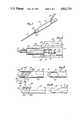
- FIG. 1is an isometric view of a surgical cutting instrument constructed in accordance with the teachings of this invention.
- FIG. 2is an enlarged fragmentary sectional view illustrating the coupling of the outer tube and the inner cutting member to the handle.
- FIG. 3is a fragmentary, exploded top plan view of the distal regions of the inner and outer tubes.
- FIG. 4is a side elevational view of the construction shown in FIG. 3.
- FIG. 5is an enlarged sectional view taken generally along line 5--5 of FIG. 3.
- FIG. 6is a top plan view of the distal region of the surgical cutting instrument showing how the cutting edges cooperate to cut material.
- FIGS. 7 and 8are top plan and side elevational views, respectively, similar to FIGS. 3 and 4, respectively, illustrating a second embodiment of the invention.
- FIG. 9is an enlarged sectional view taken generally along line 9--9 of FIG. 7, with the inner tube being fully inserted into the outer tube.
- FIG. 10is a top plan view of the distal region of the surgical cutting instrument showing how the cutting edges cooperate to cut material.
- FIGS. 1-6show a surgical cutting instrument 11 which generally comprises a handle 13, an outer tube 15, and an inner cutting member in the form of an inner tube 17.
- the inner tube 17is slidably receivable and rotatable within the outer tube 15.
- the outer tube 15is fixedly attached to the handle 13 in a known manner, and the inner tube 17 is drivable by a motor 19 carried by the handle 13.
- the handle 13also provides a passage 21 which is coupled by a conduit 23 (FIG. 1) to a vacuum source (not shown) for applying suction pressure to the interior of the inner tube 17 to withdraw material severed during operation of the cutting instrument.
- a sleeve 25is suitably fixedly attached to the outer tube 15, and the sleeve in turn is releasably mounted on a collar 27 in a conventional manner, such as by ball detents and a key and key way (not shown).
- the collar 27is removably received within a bore 29 of the handle 13 by a conventional quick disconnect connection 30.
- the inner tube 17extends proximally of the sleeve 25 where it is coupled by a conventional coupling 31 to a drive shaft 33 (FIG. 2) of the motor 19. With this construction, the motor 19 can rotate the inner tube 17 within the outer tube 15 in a known manner.
- Vacuum pressuremay be applied to the interior of the inner tube 17 via the passage 21 and a radial opening 35 in the coupling 31 in a conventional manner.
- the bearing support for the rotation of the inner tube 17can be provided in whole or in part by the outer tube 15 or in any other suitable manner known in the art.
- the outer tube 15is sized for insertion through an opening, such as a puncture or incision, in a patient.
- the outer tubemay be sized for insertion through an opening in the knee and may be used, for example, for cutting synovial tissue in the knee.
- the outer tube 15has a peripheral wall 37 and an end wall 39 at a distal end of the outer tube.
- the peripheral wall 37is preferably cylindrical
- the end wallin this embodiment, is preferably generally hemispherical and of the same radius as the peripheral wall.
- the outer tube 15has a passage 41 (FIG. 5) which extends completely through the outer tube from a proximal end 43 (FIG. 2) all the way to the end wall 39 at the distal end of the outer tube.
- the passage 41is cylindrical throughout the full length of the peripheral wall 37 and is hemispherical within the hemispherical end wall 39.
- the outer tube 15has openings 45, 45a and 45b.
- This inventiondiffers from the prior art in that the outer tube 15 has multiple openings 45, 45a and 45b of a particular configuration and orientation and in the manner in which these openings cooperate with the inner tube 17.
- the openings 45, 45a and 45bcould be of different configurations, in this embodiment, the openings are substantially identical.
- the openingsare arranged longitudinally along the outer tube 15 with the opening 45 being the most distal.
- the openings 45a and 45blie entirely in the peripheral wall 37, and the opening 45 lies primarily in the peripheral wall and partially in the end wall 39.
- Each of the openings 45-45bhas axially spaced, cutting edges 47 and 49 defining substantial portions of the periphery of the associated opening. At least one of the edges 47 and 49 of each of the openings 45-45b and, preferably both of such edges, is substantially straight as viewed in a particular direction perpendicular to a longitudinal axis 51 of the outer tube 15. As shown in FIG. 3, this particular direction is a top plan view looking directly down on the openings 45-45b.
- the edges 47 and 49 of the opening 45are parallel, and preferably all of these edges are parallel.
- each of the openings 45-45bare joined by relatively short, axial cutting edges 53.
- the cutting edges 47form the distal edges of each of the associated openings 45-45b, and the cutting edges 49 form the proximal edges of such openings.
- the axial edges 53are straight as viewed in FIG. 3, except that the lower (as viewed in FIG. 3) axial edge 53 of the opening 45 is curved slightly because of its presence in the hemispherical end wall 39. Except for the curvature of this one cutting edge 53, the openings 45-45b are completely identical, and the curvature of this one cutting edge 53 does not keep the openings 45-45b from being substantially or essentially identical.
- At least one, and preferably both, of the cutting edges 47 and 49 of each of the openings 45-45bextend circumferentially of the outer tube 15 at an acute angle relative to a radial plane as shown in FIG. 3.
- at least one, and preferably all, of the openings 45-45bextend circumferentially of the outer tube 15 for at least 90 degrees, and in this embodiment, the openings extend circumferentially for less than 180 degrees and about 160 degrees. This lengthens the cutting edges 47 and 49.
- Each of the openings 45-45bis relatively large in area when compared with the usual small diameter circular whisker opening. Moreover, the ratio of the length of the periphery of each of the openings 45-45b to the outside diameter of the outer tube 15 in this embodiment is about 2.33 to 1.
- the cutting edges 47, 49 and 53may be straight or beveled as desired. In the illustrated embodiment, the cutting edges 47 are straight as shown in FIG. 5, and the cutting edges 49 and 53 are beveled to slope downwardly as they extend inwardly when the outer tube 15 is oriented with the opening 45a facing directly upwardly. However, whether or not the cutting edges 47 and 49 are beveled, the sides of the openings 45-45b defined by the cutting edges 47 and 49 are parallel as viewed in FIG. 3.
- the inner tube 17can be of various different constructions, in this embodiment, it includes a cylindrical, peripheral wall 71 and a hemispherical end wall 73 at the distal end of the inner tube.
- the inner tube 17has a passage 75 which extends from a proximal end 77 (FIG. 2) of the inner tube all the way to the end wall 73.
- the inner tube 17has an opening 79 and a cutting edge 81 extending along the periphery of the opening 79 and completely circumscribing the opening.
- the cutting edge 81can be of any configuration that will appropriately cooperate with the cutting edges 47, 49 and 53 to shear material to be cut in a scissors-like fashion while crowding such material generally toward one of the axial cutting edges 53.
- the opening 79 and the cutting edge 81are generally oval, and more specifically, are generally elliptical as shown in FIG. 3.
- the cutting edge 81 and, therefore, the opening 79are in both the peripheral wall 71 and the end wall 73.
- the cutting edge 81appears elliptical as viewed in FIG. 3 and forms an arc as shown in FIG. 4 which lies entirely above a central longitudinal axis 82 of the inner tube 17.
- the opening 79can be of various other configurations, including a configuration which matches the configuration of the openings 45-45b of the outer tube 15. If desired, an appropriate cutting edge may be provided on a non-tubular rotatable member, such as a helix, in lieu of on the inner tube 17.
- the cutting instrument 11In use of the cutting instrument 11, it is inserted through an opening in the knee to a region, such as the synovial tissue, which is to be cut, and the motor 19 is energized to begin unidirectional rotation of the inner tube 17 within the outer tube 15. This moves the cutting edge 81 along the cutting edges 47 and 49 of each of the openings 45-45b as generally illustrated in FIG. 6 to provide shearing or scissors-like cutting along all of the cutting edges 47 and 49 while crowding material toward the short axial cutting edges 53. This provides a reliable and effective cutting of the material along the cutting edges 47 and 49 in a way that consistency and cutting efficiency are enhanced.
- the cutting action along the cutting edges of the openings 45-45bis out of phase with each other, i.e., the cutting edge 81 at any one instant is in a different relative position with respect to each opening 45-45b as shown in FIG. 6.
- the inner tube 17can be rotated in either direction within the outer tube 15, and the same desirable cutting action is achieved.
- the outer tube 15may be moved longitudinally such that the edges 47 and 49 provide a curetting-type of action for cutting and scraping material. Suction is applied through the passage 21, the opening 35 and the passage 75 of the inner tube 17 so as to remove severed material after it is cut so that the cutting instrument need not be withdrawn from the incision to accomplish this.
- FIGS. 7-10show a cutting instrument 111 which is identical to the cutting instrument 11 in all respects not shown or described herein. Portions of the cutting instrument 111 corresponding to portions of the cutting instrument 11 are designated by reference characters increased by 100 over those employed for the cutting instrument 11.
- the primary difference between the cutting instruments 11 and 111is in the configuration of the openings 145 and 145a.
- Each of the openings 145 and 145ais identical, and in this embodiment, the opening 45b is eliminated.
- the openings 145 and 145ahave parallel cutting edges 149 of the same length, orientation and configuration as the cutting edges 49, except that the cutting edges 149 in this embodiment, are not beveled.
- the cutting edges 149are straight as viewed in a particular direction, i.e., a top plan view (FIG. 7) looking straight down on the openings 145 and 145a.
- Each of the openings 145 and 145aalso has a curved cutting edge 83 which is part oval as viewed in FIG. 7 and which intersects the opposite ends of the associated cutting edge 149 to form corners 85. Accordingly, the cutting edges 83 and 149 define the full periphery of the associated opening 145 and 145a.
- the opening 145ais located entirely in the peripheral wall 137, and the opening 145 is located primarily in the peripheral wall and partly in the end wall 139.
- Each of the openings 145 and 145amay be visualized as formed by intersecting planes which intersect on one side of the axis 151 to form the cutting edges 83 and 149. These cutting planes enter the outer tube 115 from such one side, and the intersection of the planes forms the corners 85.
- the openings 145 and 145amay be formed by rotating cutting tools (not shown), and thus reference herein to formation of the openings with planes is only for purposes of visualization of the opening geometry and does not refer to the process of cutting the openings or to whether or not the edges may be beveled.
- the openings 145 and 145amay have the same circumferential extent as the openings 45-45b.
- the ratio of the length of the periphery of each of the openings 145-145a to the outside diameter of the outer tube 115is about 3.38 to 1.
- the operation of the cutting instrument 111is essentially as described above for the cutting instrument 11.
- the shearing or scissors actionproceeds along the cutting edges 83 and 149 toward the corners 85 by virtue of the cooperation between the cutting edges 83 and 149 and the cutting edge 181.
- the material being cuttends to be trapped in the corner 85 and is prevented from escaping.
- the shearing actionterminates essentially simultaneously along the cutting edges 83 and 149 at the corner 85 of the opening 145; whereas, with the opening 145a, the shearing action along the cutting edge 149 is complete slightly before the completion of the shearing action along the cutting edge 83.
Landscapes
- Health & Medical Sciences (AREA)
- Surgery (AREA)
- Life Sciences & Earth Sciences (AREA)
- Public Health (AREA)
- Animal Behavior & Ethology (AREA)
- Engineering & Computer Science (AREA)
- Biomedical Technology (AREA)
- Heart & Thoracic Surgery (AREA)
- Ophthalmology & Optometry (AREA)
- Veterinary Medicine (AREA)
- Nuclear Medicine, Radiotherapy & Molecular Imaging (AREA)
- General Health & Medical Sciences (AREA)
- Orthopedic Medicine & Surgery (AREA)
- Molecular Biology (AREA)
- Medical Informatics (AREA)
- Vascular Medicine (AREA)
- Surgical Instruments (AREA)
Abstract
Description
Claims (19)
Priority Applications (2)
| Application Number | Priority Date | Filing Date | Title |
|---|---|---|---|
| US07/085,644US4811734A (en) | 1987-08-13 | 1987-08-13 | Surgical cutting instrument |
| US07/103,828US4867157A (en) | 1987-08-13 | 1987-09-30 | Surgical cutting instrument |
Applications Claiming Priority (1)
| Application Number | Priority Date | Filing Date | Title |
|---|---|---|---|
| US07/085,644US4811734A (en) | 1987-08-13 | 1987-08-13 | Surgical cutting instrument |
Related Child Applications (1)
| Application Number | Title | Priority Date | Filing Date |
|---|---|---|---|
| US07/103,828Continuation-In-PartUS4867157A (en) | 1987-08-13 | 1987-09-30 | Surgical cutting instrument |
Publications (1)
| Publication Number | Publication Date |
|---|---|
| US4811734Atrue US4811734A (en) | 1989-03-14 |
Family
ID=22193003
Family Applications (1)
| Application Number | Title | Priority Date | Filing Date |
|---|---|---|---|
| US07/085,644Expired - LifetimeUS4811734A (en) | 1987-08-13 | 1987-08-13 | Surgical cutting instrument |
Country Status (1)
| Country | Link |
|---|---|
| US (1) | US4811734A (en) |
Cited By (77)
| Publication number | Priority date | Publication date | Assignee | Title |
|---|---|---|---|---|
| US4923441A (en)* | 1989-02-23 | 1990-05-08 | Concept, Inc. | Surgical cutting instrument with titanium nitride coating on an inner tubular member |
| EP0442263A1 (en)* | 1990-01-30 | 1991-08-21 | Microcision, Inc. | Atherectomy device with helical cutter |
| US5084052A (en)* | 1989-02-09 | 1992-01-28 | Baxter International Inc. | Surgical cutting instrument with plurality of openings |
| US5437630A (en)* | 1993-10-27 | 1995-08-01 | Stryker Corporation | Arthroscopic cutter having curved rotatable drive |
| US5601583A (en)* | 1995-02-15 | 1997-02-11 | Smith & Nephew Endoscopy Inc. | Surgical instrument |
| US5665101A (en)* | 1996-04-01 | 1997-09-09 | Linvatec Corporation | Endoscopic or open lipectomy instrument |
| US5690660A (en)* | 1993-10-27 | 1997-11-25 | Stryker Corporation | Arthroscopic cutter having curved rotatable drive |
| US5755731A (en)* | 1994-04-15 | 1998-05-26 | Smith & Nephew Dyonics, Inc. | Curved surgical instrument with segmented inner member |
| US5792167A (en)* | 1996-09-13 | 1998-08-11 | Stryker Corporation | Surgical irrigation pump and tool system |
| WO1999017664A1 (en)* | 1997-10-06 | 1999-04-15 | Smith & Nephew, Inc. | Methods and apparatus for removing veins |
| US5910152A (en)* | 1996-09-24 | 1999-06-08 | Xomed Surgical Products, Inc. | Method for supplying a powered handpiece |
| US6053923A (en)* | 1998-03-17 | 2000-04-25 | Arthrotek, Inc. | Method and apparatus for abrading tissue |
| US6332886B1 (en) | 1999-02-03 | 2001-12-25 | Synthes (Usa) | Surgical reamer and method of using same |
| US6342061B1 (en) | 1996-09-13 | 2002-01-29 | Barry J. Kauker | Surgical tool with integrated channel for irrigation |
| US20020082632A1 (en)* | 1997-10-06 | 2002-06-27 | Smith & Nephew North America, A Delaware Corporation | Methods and apparatus for removing veins |
| US6478750B1 (en)* | 2000-11-17 | 2002-11-12 | Janet F. Morrison | Hair collection device and methods of use thereof |
| US6783533B2 (en) | 2001-11-21 | 2004-08-31 | Sythes Ag Chur | Attachable/detachable reaming head for surgical reamer |
| US6783532B2 (en) | 1999-02-02 | 2004-08-31 | Synthes (Usa) | Device for removing bone tissue |
| US20050144783A1 (en)* | 2003-12-29 | 2005-07-07 | Wai-Wah Yiu | Shearing device including ridges |
| US20050182432A1 (en)* | 2004-02-18 | 2005-08-18 | Fanton Gary S. | Apparatus and methods for clearing obstructions from surgical cutting instruments |
| USD509626S1 (en) | 2003-12-29 | 2005-09-13 | K.I.S. Ltd. | Depilatory device tip |
| US20060036272A1 (en)* | 2004-07-29 | 2006-02-16 | X-Sten, Inc. | Spinal ligament modification |
| US20070027464A1 (en)* | 2005-07-29 | 2007-02-01 | X-Sten, Corp. | Device for resecting spinal tissue |
| US20070055263A1 (en)* | 2005-07-29 | 2007-03-08 | X-Sten Corp. | Tools for Percutaneous Spinal Ligament Decompression and Device for Supporting Same |
| US20070276390A1 (en)* | 2006-05-09 | 2007-11-29 | X-Sten, Inc. | Ipsilateral Approach to Minimally Invasive Ligament Decompression Procedure |
| US20080021488A1 (en)* | 2006-07-24 | 2008-01-24 | Sascha Berberich | Medical Instrument for Cutting Tissue |
| US20080111101A1 (en)* | 2006-11-09 | 2008-05-15 | Jason Keleher | Compositions and methods for CMP of low-k-dielectric materials |
| US20080208233A1 (en)* | 2006-12-21 | 2008-08-28 | Aaron Barnes | Disposable vitrectomy handpiece |
| US20080221383A1 (en)* | 2007-02-12 | 2008-09-11 | Vertos Medical, Inc. | Tissue excision devices and methods |
| US20090088784A1 (en)* | 2007-09-27 | 2009-04-02 | Doheny Eye Institute | Selectable stroke cutter |
| US20090118709A1 (en)* | 2007-11-06 | 2009-05-07 | Vertos Medical, Inc. A Delaware Corporation | Tissue Excision Tool, Kits and Methods of Using the Same |
| EP1901666A4 (en)* | 2005-07-11 | 2010-01-06 | Kyphon Inc | Apparatus and methods of tissue removal within a spine |
| USD610259S1 (en) | 2008-10-23 | 2010-02-16 | Vertos Medical, Inc. | Tissue modification device |
| USD611146S1 (en) | 2008-10-23 | 2010-03-02 | Vertos Medical, Inc. | Tissue modification device |
| USD619253S1 (en) | 2008-10-23 | 2010-07-06 | Vertos Medical, Inc. | Tissue modification device |
| USD619252S1 (en) | 2008-10-23 | 2010-07-06 | Vertos Medical, Inc. | Tissue modification device |
| USD621939S1 (en) | 2008-10-23 | 2010-08-17 | Vertos Medical, Inc. | Tissue modification device |
| US20100211090A1 (en)* | 2009-02-16 | 2010-08-19 | Sascha Berberich | Medical Instrument For Cutting Tissue |
| USD635671S1 (en) | 2008-10-23 | 2011-04-05 | Vertos Medical, Inc. | Tissue modification device |
| CN102327159A (en)* | 2011-08-18 | 2012-01-25 | 杨勋 | Dual-purpose vitreous body cutting head |
| DE102010050337A1 (en)* | 2010-11-05 | 2012-05-10 | Volker Geuder | Device for cutting and suctioning tissue |
| US20120130274A1 (en)* | 2010-11-19 | 2012-05-24 | Jean-Charles Persat | Tissue sampling tool, in particular for adipose tissue |
| WO2013009576A1 (en) | 2011-07-08 | 2013-01-17 | Doheny Eye Institute | Ocular lens cutting device |
| DE102012103153A1 (en)* | 2012-04-12 | 2013-10-17 | Karl Storz Gmbh & Co. Kg | Medical instrument for separating tissue and cartilage |
| US20140171997A1 (en)* | 2012-12-18 | 2014-06-19 | Alcon Research, Ltd. | Multi-Port Vitrectomy Probe with Dual Cutting Edges |
| WO2015175292A1 (en) | 2014-05-16 | 2015-11-19 | Gyrus Acmi, Inc., D.B.A. Olympus Surgical Technologies America | Apparatus and method for cutting tissue |
| US20160022489A1 (en)* | 2013-03-13 | 2016-01-28 | D.O.R.C. Dutch Ophthalmic Research Center (International) B.V. | Eye surgical cutting tool |
| US20160066945A1 (en)* | 2014-09-08 | 2016-03-10 | Medtronic-Xomed, Inc. | Tumor margin device |
| DE102014219616A1 (en)* | 2014-09-26 | 2016-03-31 | Geuder Ag | Device for cutting tissue |
| US20170027611A1 (en)* | 2015-07-31 | 2017-02-02 | Polygon Medical, Inc. | Polypectomy systems, devices, and methods |
| US9693898B2 (en) | 2014-11-19 | 2017-07-04 | Novartis Ag | Double-acting vitreous probe with contoured port |
| US9737322B2 (en) | 2014-09-08 | 2017-08-22 | Medtronic Xomed, Inc. | Method for resection of tumors and tissues |
| US20180110540A1 (en)* | 2016-10-20 | 2018-04-26 | Acclarent, Inc. | Multi-window surgical cutting apparatus |
| US10172644B2 (en) | 2006-03-29 | 2019-01-08 | Edge Systems Llc | Devices, systems and methods for treating the skin |
| US10179229B2 (en) | 2014-12-23 | 2019-01-15 | Edge Systems Llc | Devices and methods for treating the skin using a porous member |
| US10238812B2 (en) | 2013-03-15 | 2019-03-26 | Edge Systems Llc | Skin treatment systems and methods using needles |
| US10251675B2 (en) | 2006-03-29 | 2019-04-09 | Edge Systems Llc | Devices, systems and methods for treating the skin |
| USD847992S1 (en) | 2017-06-27 | 2019-05-07 | Polygon Medical, Inc. | Medical device handle |
| US10285731B2 (en) | 2017-06-14 | 2019-05-14 | Polygon Medical, Inc. | Polypectomy systems, devices, and methods |
| US10357642B2 (en) | 2005-12-30 | 2019-07-23 | Edge Systems Llc | Removable tips for use with skin treatment systems |
| EP1773215B2 (en)† | 2004-07-22 | 2019-07-24 | Da Rold Engineering AG | Surgical cutting instrument |
| US10556096B2 (en) | 2008-01-04 | 2020-02-11 | Edge Systems Llc | Devices and methods for skin treatment |
| US10556097B2 (en) | 2008-01-29 | 2020-02-11 | Edge Systems Llc | Devices for treating skin using treatment materials located along a tip |
| US20200178996A1 (en)* | 2018-12-10 | 2020-06-11 | Acclarent, Inc. | Method of forming suction instrument end and shaver instrument end |
| US10993743B2 (en) | 2013-03-15 | 2021-05-04 | Edge Systems Llc | Devices, systems and methods for treating the skin |
| US11020577B2 (en) | 2008-01-29 | 2021-06-01 | Edge Systems Llc | Devices and systems for treating skin surfaces |
| WO2022009048A1 (en)* | 2020-07-07 | 2022-01-13 | Johnson & Johnson Surgical Vision, Inc. | Ophthalmic curette |
| US11241357B2 (en) | 2015-07-08 | 2022-02-08 | Edge Systems Llc | Devices, systems and methods for promoting hair growth |
| US11744999B2 (en) | 2014-12-23 | 2023-09-05 | Hydra Facial LLC | Devices and methods for treating the skin |
| US20230293201A1 (en)* | 2020-08-31 | 2023-09-21 | Sven Behrendt | Surgical shaver |
| USD1016615S1 (en) | 2021-09-10 | 2024-03-05 | Hydrafacial Llc | Container for a skin treatment device |
| USD1042807S1 (en) | 2021-10-11 | 2024-09-17 | Hydrafacial Llc | Skin treatment tip |
| US12102348B2 (en) | 2016-09-07 | 2024-10-01 | Vertos Medical, Inc. | Percutaneous lateral recess resection methods and instruments |
| USD1065551S1 (en) | 2021-09-10 | 2025-03-04 | Hydrafacial Llc | Skin treatment device |
| US12295618B2 (en) | 2020-01-06 | 2025-05-13 | Hydrafacial Llc | Skin treatment tool applicator tip |
| US12324572B2 (en) | 2022-06-16 | 2025-06-10 | Vertos Medical, Inc. | Integrated instrument assembly |
| USD1084369S1 (en) | 2023-02-10 | 2025-07-15 | Hydrafacial Llc | Skin treatment tip |
Citations (14)
| Publication number | Priority date | Publication date | Assignee | Title |
|---|---|---|---|---|
| CA452936A (en)* | 1948-11-30 | P. Levesque Joseph | Hair cutter | |
| US2729210A (en)* | 1954-06-22 | 1956-01-03 | Frank C Spencer | Medical instrument |
| DE1067176B (en)* | 1956-01-28 | 1959-10-15 | Kaj Farso Madsen | Nasogastric tube |
| US3618611A (en)* | 1969-03-05 | 1971-11-09 | Julius C Urban | Vacuum rotary dissector |
| US3815604A (en)* | 1972-06-19 | 1974-06-11 | Malley C O | Apparatus for intraocular surgery |
| US3945375A (en)* | 1972-04-04 | 1976-03-23 | Surgical Design Corporation | Rotatable surgical instrument |
| US3990453A (en)* | 1973-04-25 | 1976-11-09 | Douvas Nicholas G | Apparatus for cataract surgery |
| US4099529A (en)* | 1976-09-20 | 1978-07-11 | Peyman Gholam A | Wide-angle cutter vitrophage |
| US4111207A (en)* | 1976-10-28 | 1978-09-05 | David Kopf Instruments | Notched tubular cutting instrument |
| US4203444A (en)* | 1977-11-07 | 1980-05-20 | Dyonics, Inc. | Surgical instrument suitable for closed surgery such as of the knee |
| US4274414A (en)* | 1979-02-21 | 1981-06-23 | Dyonics, Inc. | Surgical instrument |
| USD275127S (en) | 1981-07-02 | 1984-08-14 | Edwards Edward K | Curette |
| US4598710A (en)* | 1984-01-20 | 1986-07-08 | Urban Engineering Company, Inc. | Surgical instrument and method of making same |
| US4603694A (en)* | 1983-03-08 | 1986-08-05 | Richards Medical Company | Arthroscopic shaver |
- 1987
- 1987-08-13USUS07/085,644patent/US4811734A/ennot_activeExpired - Lifetime
Patent Citations (15)
| Publication number | Priority date | Publication date | Assignee | Title |
|---|---|---|---|---|
| CA452936A (en)* | 1948-11-30 | P. Levesque Joseph | Hair cutter | |
| US2729210A (en)* | 1954-06-22 | 1956-01-03 | Frank C Spencer | Medical instrument |
| DE1067176B (en)* | 1956-01-28 | 1959-10-15 | Kaj Farso Madsen | Nasogastric tube |
| US3618611A (en)* | 1969-03-05 | 1971-11-09 | Julius C Urban | Vacuum rotary dissector |
| US3945375A (en)* | 1972-04-04 | 1976-03-23 | Surgical Design Corporation | Rotatable surgical instrument |
| US3815604A (en)* | 1972-06-19 | 1974-06-11 | Malley C O | Apparatus for intraocular surgery |
| US3990453A (en)* | 1973-04-25 | 1976-11-09 | Douvas Nicholas G | Apparatus for cataract surgery |
| US4099529A (en)* | 1976-09-20 | 1978-07-11 | Peyman Gholam A | Wide-angle cutter vitrophage |
| US4111207A (en)* | 1976-10-28 | 1978-09-05 | David Kopf Instruments | Notched tubular cutting instrument |
| US4203444A (en)* | 1977-11-07 | 1980-05-20 | Dyonics, Inc. | Surgical instrument suitable for closed surgery such as of the knee |
| US4203444B1 (en)* | 1977-11-07 | 1987-07-21 | ||
| US4274414A (en)* | 1979-02-21 | 1981-06-23 | Dyonics, Inc. | Surgical instrument |
| USD275127S (en) | 1981-07-02 | 1984-08-14 | Edwards Edward K | Curette |
| US4603694A (en)* | 1983-03-08 | 1986-08-05 | Richards Medical Company | Arthroscopic shaver |
| US4598710A (en)* | 1984-01-20 | 1986-07-08 | Urban Engineering Company, Inc. | Surgical instrument and method of making same |
Non-Patent Citations (4)
| Title |
|---|
| Arthroscopic Surgery Blades, Dyonics, Inc., R 86 7129 Rev. B8M (1986).* |
| Arthroscopic Surgery Blades, Dyonics, Inc., R-86 7129 Rev.-B8M (1986). |
| New and Controversial Aspects of Vetreoretinal Surgery, "The Visc and the Vitreomicroscope", Jean-Marie Parel, C.V. Mosby Co., St. Louis (1977). |
| New and Controversial Aspects of Vetreoretinal Surgery, The Visc and the Vitreomicroscope , Jean Marie Parel, C.V. Mosby Co., St. Louis (1977).* |
Cited By (152)
| Publication number | Priority date | Publication date | Assignee | Title |
|---|---|---|---|---|
| US5084052A (en)* | 1989-02-09 | 1992-01-28 | Baxter International Inc. | Surgical cutting instrument with plurality of openings |
| US4923441A (en)* | 1989-02-23 | 1990-05-08 | Concept, Inc. | Surgical cutting instrument with titanium nitride coating on an inner tubular member |
| EP0442263A1 (en)* | 1990-01-30 | 1991-08-21 | Microcision, Inc. | Atherectomy device with helical cutter |
| US5437630A (en)* | 1993-10-27 | 1995-08-01 | Stryker Corporation | Arthroscopic cutter having curved rotatable drive |
| US5690660A (en)* | 1993-10-27 | 1997-11-25 | Stryker Corporation | Arthroscopic cutter having curved rotatable drive |
| US5755731A (en)* | 1994-04-15 | 1998-05-26 | Smith & Nephew Dyonics, Inc. | Curved surgical instrument with segmented inner member |
| US5601583A (en)* | 1995-02-15 | 1997-02-11 | Smith & Nephew Endoscopy Inc. | Surgical instrument |
| US5665101A (en)* | 1996-04-01 | 1997-09-09 | Linvatec Corporation | Endoscopic or open lipectomy instrument |
| US5720760A (en)* | 1996-04-01 | 1998-02-24 | Linvatec Corporation | Endoscopic or open lipectomy instrument |
| US6342061B1 (en) | 1996-09-13 | 2002-01-29 | Barry J. Kauker | Surgical tool with integrated channel for irrigation |
| US5792167A (en)* | 1996-09-13 | 1998-08-11 | Stryker Corporation | Surgical irrigation pump and tool system |
| US6007556A (en)* | 1996-09-13 | 1999-12-28 | Stryker Corporation | Surgical irrigation pump and tool system |
| EP1256322A3 (en)* | 1996-09-24 | 2003-03-26 | Xomed Surgical Products, Inc. | Powered handpiece and surgical blades and methods thereof |
| US6010477A (en)* | 1996-09-24 | 2000-01-04 | Xomed Surgical Products, Inc. | Surgical blades assembly |
| US6221088B1 (en) | 1996-09-24 | 2001-04-24 | Xomed Surgical Products, Inc. | Powered handpiece and surgical blades and methods thereof |
| US5910152A (en)* | 1996-09-24 | 1999-06-08 | Xomed Surgical Products, Inc. | Method for supplying a powered handpiece |
| US5916231A (en)* | 1996-09-24 | 1999-06-29 | Xomed Surgical Products, Inc. | Powered handpiece and surgical blades and methods therefor |
| US5957945A (en)* | 1996-09-24 | 1999-09-28 | Xomed Surgical Products, Inc. | Powered handpiece system |
| US7018391B2 (en) | 1997-10-06 | 2006-03-28 | Smith & Nephew North America | Methods and apparatus for removing veins |
| WO1999017664A1 (en)* | 1997-10-06 | 1999-04-15 | Smith & Nephew, Inc. | Methods and apparatus for removing veins |
| US8177800B2 (en) | 1997-10-06 | 2012-05-15 | Inavein Llc | Methods and apparatus for removing veins |
| AU735855B2 (en)* | 1997-10-06 | 2001-07-19 | Inavein Llc | Methods and apparatus for removing veins |
| US20020082632A1 (en)* | 1997-10-06 | 2002-06-27 | Smith & Nephew North America, A Delaware Corporation | Methods and apparatus for removing veins |
| US6436116B1 (en) | 1997-10-06 | 2002-08-20 | Smith & Nephew, Inc. | Methods and apparatus for removing veins |
| US20060229647A1 (en)* | 1997-10-06 | 2006-10-12 | Smith & Nephew North America, A Delaware Corporation | Methods and apparatus for removing veins |
| US6053923A (en)* | 1998-03-17 | 2000-04-25 | Arthrotek, Inc. | Method and apparatus for abrading tissue |
| US6783532B2 (en) | 1999-02-02 | 2004-08-31 | Synthes (Usa) | Device for removing bone tissue |
| US6332886B1 (en) | 1999-02-03 | 2001-12-25 | Synthes (Usa) | Surgical reamer and method of using same |
| US6478750B1 (en)* | 2000-11-17 | 2002-11-12 | Janet F. Morrison | Hair collection device and methods of use thereof |
| US6783533B2 (en) | 2001-11-21 | 2004-08-31 | Sythes Ag Chur | Attachable/detachable reaming head for surgical reamer |
| USD509626S1 (en) | 2003-12-29 | 2005-09-13 | K.I.S. Ltd. | Depilatory device tip |
| US20050144783A1 (en)* | 2003-12-29 | 2005-07-07 | Wai-Wah Yiu | Shearing device including ridges |
| US20050182432A1 (en)* | 2004-02-18 | 2005-08-18 | Fanton Gary S. | Apparatus and methods for clearing obstructions from surgical cutting instruments |
| EP1773215B2 (en)† | 2004-07-22 | 2019-07-24 | Da Rold Engineering AG | Surgical cutting instrument |
| US20060036272A1 (en)* | 2004-07-29 | 2006-02-16 | X-Sten, Inc. | Spinal ligament modification |
| US20060036211A1 (en)* | 2004-07-29 | 2006-02-16 | X-Sten, Inc. | Spinal ligament modification kit |
| US20060184175A1 (en)* | 2004-07-29 | 2006-08-17 | X-Sten, Inc. | Spinal ligament modification devices |
| US20060235451A1 (en)* | 2004-07-29 | 2006-10-19 | X-Sten | Ligament Decompression Tool with Tissue Engaging Device |
| US20060235452A1 (en)* | 2004-07-29 | 2006-10-19 | X-Sten | Ligament Decompression Tool with Tissue Removal Device |
| US20060264994A1 (en)* | 2004-07-29 | 2006-11-23 | X-Sten | Spinal Decompression Method Using Tissue Retraction |
| US20060036271A1 (en)* | 2004-07-29 | 2006-02-16 | X-Sten, Inc. | Spinal ligament modification devices |
| US20060206115A1 (en)* | 2004-07-29 | 2006-09-14 | X-Sten | Ligament decompression kit with contrast |
| US7896879B2 (en) | 2004-07-29 | 2011-03-01 | Vertos Medical, Inc. | Spinal ligament modification |
| EP1901666A4 (en)* | 2005-07-11 | 2010-01-06 | Kyphon Inc | Apparatus and methods of tissue removal within a spine |
| US20070055263A1 (en)* | 2005-07-29 | 2007-03-08 | X-Sten Corp. | Tools for Percutaneous Spinal Ligament Decompression and Device for Supporting Same |
| US8696671B2 (en) | 2005-07-29 | 2014-04-15 | Vertos Medical Inc. | Percutaneous tissue excision devices |
| US8882772B2 (en) | 2005-07-29 | 2014-11-11 | Vertos Medical, Inc. | Percutaneous tissue excision devices and methods |
| US20070055215A1 (en)* | 2005-07-29 | 2007-03-08 | X-Sten Corp. | Percutaneous Tissue Excision Devices and Methods |
| US8894653B2 (en) | 2005-07-29 | 2014-11-25 | Vertos Medical, Inc. | Percutaneous tissue excision devices and methods |
| US20070027464A1 (en)* | 2005-07-29 | 2007-02-01 | X-Sten, Corp. | Device for resecting spinal tissue |
| US11547840B2 (en) | 2005-12-30 | 2023-01-10 | Hydrafacial Llc | Devices and methods for treating skin |
| US10357642B2 (en) | 2005-12-30 | 2019-07-23 | Edge Systems Llc | Removable tips for use with skin treatment systems |
| US10357641B2 (en) | 2005-12-30 | 2019-07-23 | Edge Systems Llc | Tips for skin treatment device |
| US11446477B2 (en) | 2005-12-30 | 2022-09-20 | Hydrafacial Llc | Devices and methods for treating skin |
| US11612726B2 (en) | 2005-12-30 | 2023-03-28 | Hydrafacial Llc | Devices and methods for treating skin |
| US11865287B2 (en) | 2005-12-30 | 2024-01-09 | Hydrafacial Llc | Devices and methods for treating skin |
| US12053607B2 (en) | 2005-12-30 | 2024-08-06 | Hydrafacial Llc | Devices and methods for treating skin |
| US10251675B2 (en) | 2006-03-29 | 2019-04-09 | Edge Systems Llc | Devices, systems and methods for treating the skin |
| US10172644B2 (en) | 2006-03-29 | 2019-01-08 | Edge Systems Llc | Devices, systems and methods for treating the skin |
| US11717326B2 (en) | 2006-03-29 | 2023-08-08 | Hydrafacial Llc | Devices, systems and methods for treating the skin |
| US8734477B2 (en) | 2006-05-09 | 2014-05-27 | Vertos Medical, Inc. | Translaminar approach to minimally invasive ligament decompression procedure |
| US8608762B2 (en) | 2006-05-09 | 2013-12-17 | Vertos Medical, Inc. | Translaminar approach to minimally invasive ligament decompression procedure |
| US7942830B2 (en) | 2006-05-09 | 2011-05-17 | Vertos Medical, Inc. | Ipsilateral approach to minimally invasive ligament decompression procedure |
| US20070276390A1 (en)* | 2006-05-09 | 2007-11-29 | X-Sten, Inc. | Ipsilateral Approach to Minimally Invasive Ligament Decompression Procedure |
| US20090036936A1 (en)* | 2006-05-09 | 2009-02-05 | Vertos Medical, Inc. | Translaminar approach to minimally invasive ligament decompression procedure |
| US8529593B2 (en) | 2006-07-24 | 2013-09-10 | Karl Storz Gmbh & Co. Kg | Medical instrument for cutting tissue |
| EP1882455A1 (en)* | 2006-07-24 | 2008-01-30 | Karl Storz GmbH & Co. KG | Medical instrument for cutting tissue |
| US20080021488A1 (en)* | 2006-07-24 | 2008-01-24 | Sascha Berberich | Medical Instrument for Cutting Tissue |
| US20080111101A1 (en)* | 2006-11-09 | 2008-05-15 | Jason Keleher | Compositions and methods for CMP of low-k-dielectric materials |
| US9750639B2 (en) | 2006-12-21 | 2017-09-05 | Doheny Eye Institute | Disposable vitrectomy handpiece |
| US20080208233A1 (en)* | 2006-12-21 | 2008-08-28 | Aaron Barnes | Disposable vitrectomy handpiece |
| US20080221383A1 (en)* | 2007-02-12 | 2008-09-11 | Vertos Medical, Inc. | Tissue excision devices and methods |
| US8172865B2 (en) | 2007-09-27 | 2012-05-08 | Doheny Eye Institute | Selectable stroke cutter |
| US20090088784A1 (en)* | 2007-09-27 | 2009-04-02 | Doheny Eye Institute | Selectable stroke cutter |
| US20090118709A1 (en)* | 2007-11-06 | 2009-05-07 | Vertos Medical, Inc. A Delaware Corporation | Tissue Excision Tool, Kits and Methods of Using the Same |
| US10556096B2 (en) | 2008-01-04 | 2020-02-11 | Edge Systems Llc | Devices and methods for skin treatment |
| US11883621B2 (en) | 2008-01-04 | 2024-01-30 | Hydrafacial Llc | Devices and methods for skin treatment |
| US12186513B2 (en) | 2008-01-29 | 2025-01-07 | Hydrafacial Llc | Devices, systems and methods for skin treatment |
| US12005217B2 (en) | 2008-01-29 | 2024-06-11 | Hydrafacial Llc | Devices, systems and methods for skin treatment |
| US11020577B2 (en) | 2008-01-29 | 2021-06-01 | Edge Systems Llc | Devices and systems for treating skin surfaces |
| US12161830B2 (en) | 2008-01-29 | 2024-12-10 | Hydrafacial Llc | Devices, systems, and methods for treating the skin |
| US10556097B2 (en) | 2008-01-29 | 2020-02-11 | Edge Systems Llc | Devices for treating skin using treatment materials located along a tip |
| USD610259S1 (en) | 2008-10-23 | 2010-02-16 | Vertos Medical, Inc. | Tissue modification device |
| USD619253S1 (en) | 2008-10-23 | 2010-07-06 | Vertos Medical, Inc. | Tissue modification device |
| USD611146S1 (en) | 2008-10-23 | 2010-03-02 | Vertos Medical, Inc. | Tissue modification device |
| USD621939S1 (en) | 2008-10-23 | 2010-08-17 | Vertos Medical, Inc. | Tissue modification device |
| USD676964S1 (en) | 2008-10-23 | 2013-02-26 | Vertos Medical, Inc. | Tissue modification device |
| USD619252S1 (en) | 2008-10-23 | 2010-07-06 | Vertos Medical, Inc. | Tissue modification device |
| USD635671S1 (en) | 2008-10-23 | 2011-04-05 | Vertos Medical, Inc. | Tissue modification device |
| DE102009010561A1 (en)* | 2009-02-16 | 2010-08-19 | Karl Storz Gmbh & Co. Kg | Medical instrument for cutting tissue |
| US20100211090A1 (en)* | 2009-02-16 | 2010-08-19 | Sascha Berberich | Medical Instrument For Cutting Tissue |
| US9668918B2 (en) | 2010-11-05 | 2017-06-06 | Volker Geuder | Apparatus for cutting and aspirating tissue |
| DE102010050337A1 (en)* | 2010-11-05 | 2012-05-10 | Volker Geuder | Device for cutting and suctioning tissue |
| US20120130274A1 (en)* | 2010-11-19 | 2012-05-24 | Jean-Charles Persat | Tissue sampling tool, in particular for adipose tissue |
| US8858461B2 (en)* | 2010-11-19 | 2014-10-14 | Jean-Charles Persat | Tissue sampling tool, in particular for adipose tissue |
| US10874552B2 (en)* | 2011-07-08 | 2020-12-29 | Doheny Eye Institute | Ocular lens cutting device |
| WO2013009576A1 (en) | 2011-07-08 | 2013-01-17 | Doheny Eye Institute | Ocular lens cutting device |
| US20140364885A1 (en)* | 2011-07-08 | 2014-12-11 | Doheny Eye Institute | Ocular lens cutting device |
| CN102327159B (en)* | 2011-08-18 | 2013-05-15 | 杨勋 | Dual purpose vitreous body cutting head |
| CN102327159A (en)* | 2011-08-18 | 2012-01-25 | 杨勋 | Dual-purpose vitreous body cutting head |
| EP2679174A1 (en)* | 2012-04-12 | 2014-01-01 | Karl Storz GmbH & Co. KG | Medical instrument for severing tissue and cartilage |
| DE102012103153A1 (en)* | 2012-04-12 | 2013-10-17 | Karl Storz Gmbh & Co. Kg | Medical instrument for separating tissue and cartilage |
| US9095354B2 (en) | 2012-04-12 | 2015-08-04 | Karl Storz Gmbh & Co. Kg | Medical instrument for cutting off tissue and cartilage from a human or animal body |
| US9615969B2 (en)* | 2012-12-18 | 2017-04-11 | Novartis Ag | Multi-port vitrectomy probe with dual cutting edges |
| US20140171997A1 (en)* | 2012-12-18 | 2014-06-19 | Alcon Research, Ltd. | Multi-Port Vitrectomy Probe with Dual Cutting Edges |
| US11083623B2 (en) | 2013-03-13 | 2021-08-10 | D.O.R.C. Dutch Ophthalmic Research Center (International) B.V. | Eye surgical cutting tool |
| US20160022489A1 (en)* | 2013-03-13 | 2016-01-28 | D.O.R.C. Dutch Ophthalmic Research Center (International) B.V. | Eye surgical cutting tool |
| US10231868B2 (en)* | 2013-03-13 | 2019-03-19 | D.O.R.C. Dutch Ophtalmic Research Center (International) B.V. | Eye surgical cutting tool |
| US11517350B2 (en) | 2013-03-15 | 2022-12-06 | Hydrafacial Llc | Devices, systems and methods for treating the skin |
| US11202657B2 (en) | 2013-03-15 | 2021-12-21 | Edge Systems Llc | Devices, systems and methods for treating the skin |
| US11903615B2 (en) | 2013-03-15 | 2024-02-20 | Hydrafacial Llc | Devices, systems and methods for treating the skin |
| US10238812B2 (en) | 2013-03-15 | 2019-03-26 | Edge Systems Llc | Skin treatment systems and methods using needles |
| US11213321B2 (en) | 2013-03-15 | 2022-01-04 | Edge Systems Llc | Devices, systems and methods for treating the skin |
| US10993743B2 (en) | 2013-03-15 | 2021-05-04 | Edge Systems Llc | Devices, systems and methods for treating the skin |
| WO2015175292A1 (en) | 2014-05-16 | 2015-11-19 | Gyrus Acmi, Inc., D.B.A. Olympus Surgical Technologies America | Apparatus and method for cutting tissue |
| US20150327881A1 (en)* | 2014-05-16 | 2015-11-19 | Gyrus Acmi, Inc., D.B.A. Olympus Surgical Technologies America | Apparatus and method for cutting tissue |
| CN106794026A (en)* | 2014-05-16 | 2017-05-31 | 美国奥林匹斯外科技术吉鲁斯阿克米公司 | Device for cutting tissue and method |
| JP2017518853A (en)* | 2014-05-16 | 2017-07-13 | ジャイラス・エーシーエムアイ・インコーポレーテッド | Apparatus and method for cutting tissue |
| EP3142576A4 (en)* | 2014-05-16 | 2018-01-17 | Gyrus Acmi, Inc., D.B.A. Olympus Surgical | Apparatus and method for cutting tissue |
| US10321929B2 (en)* | 2014-05-16 | 2019-06-18 | Gyrus Acmi, Inc. | Apparatus and method for cutting tissue |
| US9737322B2 (en) | 2014-09-08 | 2017-08-22 | Medtronic Xomed, Inc. | Method for resection of tumors and tissues |
| US20160066945A1 (en)* | 2014-09-08 | 2016-03-10 | Medtronic-Xomed, Inc. | Tumor margin device |
| DE102014219616A1 (en)* | 2014-09-26 | 2016-03-31 | Geuder Ag | Device for cutting tissue |
| US20170231818A1 (en)* | 2014-09-26 | 2017-08-17 | Geuder Ag | Device for cutting tissue |
| EP3013289B1 (en)* | 2014-09-26 | 2017-03-22 | Geuder AG | Device for cutting tissue |
| US9693898B2 (en) | 2014-11-19 | 2017-07-04 | Novartis Ag | Double-acting vitreous probe with contoured port |
| US11744999B2 (en) | 2014-12-23 | 2023-09-05 | Hydra Facial LLC | Devices and methods for treating the skin |
| US11224728B2 (en) | 2014-12-23 | 2022-01-18 | Edge Systems Llc | Devices and methods for treating the skin using a porous member |
| US11925780B2 (en) | 2014-12-23 | 2024-03-12 | Hydrafacial Llc | Devices and methods for treating the skin |
| US11806495B2 (en) | 2014-12-23 | 2023-11-07 | Hydrafacial Llc | Devices and methods for treating the skin |
| US10179229B2 (en) | 2014-12-23 | 2019-01-15 | Edge Systems Llc | Devices and methods for treating the skin using a porous member |
| US11241357B2 (en) | 2015-07-08 | 2022-02-08 | Edge Systems Llc | Devices, systems and methods for promoting hair growth |
| US9707012B2 (en)* | 2015-07-31 | 2017-07-18 | Polygon Medical, Inc. | Polypectomy systems, devices, and methods |
| US20170027611A1 (en)* | 2015-07-31 | 2017-02-02 | Polygon Medical, Inc. | Polypectomy systems, devices, and methods |
| US12102348B2 (en) | 2016-09-07 | 2024-10-01 | Vertos Medical, Inc. | Percutaneous lateral recess resection methods and instruments |
| US10271871B2 (en)* | 2016-10-20 | 2019-04-30 | Acclarent, Inc. | Multi-window surgical cutting apparatus |
| US20180110540A1 (en)* | 2016-10-20 | 2018-04-26 | Acclarent, Inc. | Multi-window surgical cutting apparatus |
| US11278320B2 (en) | 2017-06-14 | 2022-03-22 | Polygon Medical, Inc. | Polypectomy systems, devices, and methods |
| US10285731B2 (en) | 2017-06-14 | 2019-05-14 | Polygon Medical, Inc. | Polypectomy systems, devices, and methods |
| USD847992S1 (en) | 2017-06-27 | 2019-05-07 | Polygon Medical, Inc. | Medical device handle |
| USD947378S1 (en) | 2017-06-27 | 2022-03-29 | Polygon Medical, Inc. | Medical device handle |
| US11826068B2 (en)* | 2018-12-10 | 2023-11-28 | Acclarent, Inc. | Method of forming suction instrument end and shaver instrument end |
| US20200178996A1 (en)* | 2018-12-10 | 2020-06-11 | Acclarent, Inc. | Method of forming suction instrument end and shaver instrument end |
| US12295618B2 (en) | 2020-01-06 | 2025-05-13 | Hydrafacial Llc | Skin treatment tool applicator tip |
| WO2022009048A1 (en)* | 2020-07-07 | 2022-01-13 | Johnson & Johnson Surgical Vision, Inc. | Ophthalmic curette |
| US20230293201A1 (en)* | 2020-08-31 | 2023-09-21 | Sven Behrendt | Surgical shaver |
| USD1065551S1 (en) | 2021-09-10 | 2025-03-04 | Hydrafacial Llc | Skin treatment device |
| USD1016615S1 (en) | 2021-09-10 | 2024-03-05 | Hydrafacial Llc | Container for a skin treatment device |
| USD1042807S1 (en) | 2021-10-11 | 2024-09-17 | Hydrafacial Llc | Skin treatment tip |
| US12324572B2 (en) | 2022-06-16 | 2025-06-10 | Vertos Medical, Inc. | Integrated instrument assembly |
| US12342999B2 (en) | 2022-06-16 | 2025-07-01 | Vertos Medical, Inc. | Integrated instrument assembly |
| USD1084369S1 (en) | 2023-02-10 | 2025-07-15 | Hydrafacial Llc | Skin treatment tip |
Similar Documents
| Publication | Publication Date | Title |
|---|---|---|
| US4811734A (en) | Surgical cutting instrument | |
| US4867157A (en) | Surgical cutting instrument | |
| US4850354A (en) | Surgical cutting instrument | |
| US4844064A (en) | Surgical cutting instrument with end and side openings | |
| US5084052A (en) | Surgical cutting instrument with plurality of openings | |
| US5964777A (en) | Surgical cutting instrument | |
| US5007917A (en) | Single blade cutter for arthroscopic surgery | |
| US6217598B1 (en) | End-cutting shaver blade | |
| US6001116A (en) | Endoscopic shaver blade with resilient cutting edges | |
| EP0651973B1 (en) | Surgical router | |
| EP1322240B1 (en) | Endoscopic shaver | |
| US6656195B2 (en) | Flexible inner tubular members and rotary tissue cutting instruments having flexible inner tubular members | |
| US9636130B2 (en) | Reciprocating rotary arthroscopic surgical instrument | |
| CA2386295C (en) | Angled rotary tissue cutting instrument with flexible inner member | |
| US5913867A (en) | Surgical instrument | |
| US5562693A (en) | Cutting blade assembly for a surgical scissors | |
| US20050054972A1 (en) | Surgical micro-burring instrument and method of performing sinus surgery | |
| WO2001022890A1 (en) | Surgical tool containment design for surgical instruments | |
| AU768557B2 (en) | Surgical cutting instrument | |
| JPH0481459B2 (en) |
Legal Events
| Date | Code | Title | Description |
|---|---|---|---|
| AS | Assignment | Owner name:BAXTER TRAVENOL LABORATORIES, INC., ONE BAXTER PAR Free format text:ASSIGNMENT OF ASSIGNORS INTEREST.;ASSIGNORS:MCGURK-BURLESON, ERIN;KOEHLER, ELMER;PACKHAM, VICTOR;REEL/FRAME:004846/0691;SIGNING DATES FROM 19870927 TO 19871014 Owner name:BAXTER TRAVENOL LABORATORIES, INC.,ILLINOIS Free format text:ASSIGNMENT OF ASSIGNORS INTEREST;ASSIGNORS:MCGURK-BURLESON, ERIN;KOEHLER, ELMER;PACKHAM, VICTOR;SIGNING DATES FROM 19870927 TO 19871014;REEL/FRAME:004846/0691 | |
| STCF | Information on status: patent grant | Free format text:PATENTED CASE | |
| FEPP | Fee payment procedure | Free format text:PAYOR NUMBER ASSIGNED (ORIGINAL EVENT CODE: ASPN); ENTITY STATUS OF PATENT OWNER: LARGE ENTITY | |
| FPAY | Fee payment | Year of fee payment:4 | |
| FPAY | Fee payment | Year of fee payment:8 | |
| AS | Assignment | Owner name:ALLEGIANCE CORPORATION, ILLINOIS Free format text:ASSIGNMENT OF ASSIGNORS INTEREST;ASSIGNOR:BAXTER INTERNATIONAL, INC.;REEL/FRAME:009227/0184 Effective date:19960930 | |
| FEPP | Fee payment procedure | Free format text:PAYOR NUMBER ASSIGNED (ORIGINAL EVENT CODE: ASPN); ENTITY STATUS OF PATENT OWNER: LARGE ENTITY Free format text:PAYER NUMBER DE-ASSIGNED (ORIGINAL EVENT CODE: RMPN); ENTITY STATUS OF PATENT OWNER: LARGE ENTITY | |
| FPAY | Fee payment | Year of fee payment:12 |