US4811608A - Force and torque converter - Google Patents
Force and torque converterDownload PDFInfo
- Publication number
- US4811608A US4811608AUS06/927,915US92791586AUS4811608AUS 4811608 AUS4811608 AUS 4811608AUS 92791586 AUS92791586 AUS 92791586AUS 4811608 AUS4811608 AUS 4811608A
- Authority
- US
- United States
- Prior art keywords
- axis
- extending
- axes
- torque
- force
- Prior art date
- Legal status (The legal status is an assumption and is not a legal conclusion. Google has not performed a legal analysis and makes no representation as to the accuracy of the status listed.)
- Expired - Lifetime
Links
Images


Classifications
- G—PHYSICS
- G01—MEASURING; TESTING
- G01L—MEASURING FORCE, STRESS, TORQUE, WORK, MECHANICAL POWER, MECHANICAL EFFICIENCY, OR FLUID PRESSURE
- G01L5/00—Apparatus for, or methods of, measuring force, work, mechanical power, or torque, specially adapted for specific purposes
- G01L5/16—Apparatus for, or methods of, measuring force, work, mechanical power, or torque, specially adapted for specific purposes for measuring several components of force
- G01L5/166—Apparatus for, or methods of, measuring force, work, mechanical power, or torque, specially adapted for specific purposes for measuring several components of force using photoelectric means
- B—PERFORMING OPERATIONS; TRANSPORTING
- B25—HAND TOOLS; PORTABLE POWER-DRIVEN TOOLS; MANIPULATORS
- B25J—MANIPULATORS; CHAMBERS PROVIDED WITH MANIPULATION DEVICES
- B25J13/00—Controls for manipulators
- B25J13/02—Hand grip control means
- B—PERFORMING OPERATIONS; TRANSPORTING
- B25—HAND TOOLS; PORTABLE POWER-DRIVEN TOOLS; MANIPULATORS
- B25J—MANIPULATORS; CHAMBERS PROVIDED WITH MANIPULATION DEVICES
- B25J13/00—Controls for manipulators
- B25J13/08—Controls for manipulators by means of sensing devices, e.g. viewing or touching devices
- B25J13/085—Force or torque sensors
- G—PHYSICS
- G01—MEASURING; TESTING
- G01L—MEASURING FORCE, STRESS, TORQUE, WORK, MECHANICAL POWER, MECHANICAL EFFICIENCY, OR FLUID PRESSURE
- G01L1/00—Measuring force or stress, in general
- G01L1/24—Measuring force or stress, in general by measuring variations of optical properties of material when it is stressed, e.g. by photoelastic stress analysis using infrared, visible light, ultraviolet
- G—PHYSICS
- G01—MEASURING; TESTING
- G01L—MEASURING FORCE, STRESS, TORQUE, WORK, MECHANICAL POWER, MECHANICAL EFFICIENCY, OR FLUID PRESSURE
- G01L5/00—Apparatus for, or methods of, measuring force, work, mechanical power, or torque, specially adapted for specific purposes
- G01L5/22—Apparatus for, or methods of, measuring force, work, mechanical power, or torque, specially adapted for specific purposes for measuring the force applied to control members, e.g. control members of vehicles, triggers
- G01L5/226—Apparatus for, or methods of, measuring force, work, mechanical power, or torque, specially adapted for specific purposes for measuring the force applied to control members, e.g. control members of vehicles, triggers to manipulators, e.g. the force due to gripping
- H—ELECTRICITY
- H01—ELECTRIC ELEMENTS
- H01H—ELECTRIC SWITCHES; RELAYS; SELECTORS; EMERGENCY PROTECTIVE DEVICES
- H01H2239/00—Miscellaneous
- H01H2239/052—Strain gauge
- Y—GENERAL TAGGING OF NEW TECHNOLOGICAL DEVELOPMENTS; GENERAL TAGGING OF CROSS-SECTIONAL TECHNOLOGIES SPANNING OVER SEVERAL SECTIONS OF THE IPC; TECHNICAL SUBJECTS COVERED BY FORMER USPC CROSS-REFERENCE ART COLLECTIONS [XRACs] AND DIGESTS
- Y10—TECHNICAL SUBJECTS COVERED BY FORMER USPC
- Y10T—TECHNICAL SUBJECTS COVERED BY FORMER US CLASSIFICATION
- Y10T74/00—Machine element or mechanism
- Y10T74/20—Control lever and linkage systems
- Y10T74/20012—Multiple controlled elements
- Y10T74/20201—Control moves in two planes
Definitions
- the present inventionrelates to a force and torque converter and has useful applications in a wide field of activities particularly where a manual motion is to be converted in to a control "signal".
- machinessuch as industrial robots, back hoes and computer graphic workstations have complex control requirements.
- a sensing systemto monitor applied forces and torques;
- an example of such a sensor systemis a system for monitoring applied forces and torques with respect to three axes in a manipulator (see U.S. Pat. No. 3,921,445 Hill and Sword).
- the manipulatoris of a hand like form comprising a pair of jaws which are relatively pivotally movable under operation of an electric motor.
- the manipulatoris defined as having a wrist and sensing means are provided for sensing the magnitude and direction of forces along three mutually orthoganal axes intersecting at the wrist and for sensing the magnitude and direction of torques about the axes.
- the form of the sensing meansis a series of sensors extending around the longitudinal axis of the manipulator.
- the present inventionconsists in an apparatus for providing command signals with respect to X, Y and Z mutually orthogonal axes, and the signals being representative of translational applied forces along the X and Z axes and applied torques about the X and Y axes, the apparatus comprising a body to which the forces and torques are applied, resilient connecting means attached to the body and mounting the body for receiving force and torque for urging the body to be displaced relative to a fixed base, and sensor means arranged to detect a response in the connecting means to any directional component of applied translational force in the X-Z plane, and to any directional component of applied torque about the X and the Y axes.
- a very small displacementresults from each of the translational force and applied torque, the connecting means being biased to a central position.
- the inventionin a form in which no displacement takes place and instead sensors respond whereby a signal is derived representative of the force or torque tending to cause displacement at each sensor.
- a system in which automatic control causes the input of some energy to resist the displacementcould be used, the input of energy having a corresponding signal generated for indicating the magnitude of the applied force.
- the inventionis especially valuable in permitting embodiments in which the applied translational force and/or the applied torque are respectively resolved into components with respect to most preferably three mutually perpendicular axes.
- the inventionwill be exemplified with reference to the most complex example in which a three dimensional device is utilised and it will be appreciated that a complex ergonomically designed control system can utilise an apparatus of this form. It is envisaged that for many applications a handle or grip for an operator will be provided and this grip is adapted to receive a translational force and a torque, the translational force being applied in any direction and the torque being about any desired axis.
- the output signalscan be used to control any required device and sophisticated control of, for example, a machine can be achieved with just one control member. This can be very important for the control of complex machines which require an operator to use a multiplicity of separate levers for controlling, e.g. hydraulic circuits. Another area in which there may be very beneficial applications is for control of devices for handicapped persons.
- the apparatusis such that only at most very small displacement results from the applied translational force and/or torque.
- the mathematical error resulting from displacementis at most exceedingly small and may be disregarded for very small angles of displacement.
- the fixed basehas a portion at which the X, Y and Z axes intersect and the connecting means comprise respective pairs of resiliently deformable connecting arms extending in the Z and Y directions, the arms of each pair extending away from the base portion in opposite directions to be connected to the body, and wherein the sensor means are adapted to detect a displacement in the respective connecting arms and provide signals permitting computation of the applied torque and/or force, the sensor means detecting torque about the Y axis or displacement in the X direction at respective locations in the arms extending in the Z direction on opposite sides of the X axis, and detecting torque about the X axis or displacement in the Z direction at respective locations in the connecting arms extending in the Y direction on opposite sides of the Z axis.
- the apparatus described in the previous paragraphis such that the remote ends of said arms are constrained against movement in second and third mutually perpendicular axes, which are each perpendicular to said first axis.
- the connecting meanscomprises three pairs of arms extending mutually perpendicularly and co-operating with the body so that the respective pairs of arms are constrained about respective mutually perpendicular axes.
- Apparatuspreferably includes signal processing means for processing the signals detected at the respective sensor means whereby output signals correspond with the applied torque and the applied translational force and, in the case of a three dimensional version of the invention, the output signals represent the resolution of the applied force and applied torque with respect to three mutually perpendicular axis.
- a second important embodiment of the inventionis one in which the connecting means comprises a series of three connecting structures each comprising an arm extending from the body and pivotally connected through a joint having universal action through at least a limited range of angles to a leg, the leg extending normally in a direction substantially at right angles to the arm to be attached to the fixed base, the biasing means biasing the leg to a central position and the leg having an ability to move against the biasing in a plane being substantially that containing the pivot point of the universal joint and substantially perpendicular to the axis of the leg.
- a universal jointproviding a limited range of motion is used for the pivotal connection between the leg and the arm.
- each of arms of the connecting structureshas its pivotal connection with its leg member such that a reference axis of the connecting member extends from a central point in the body through the pivotal connection and this reference axis is substantially at right angles to the axis along which displacement is sensed by displacement of the pivotal connection.
- each leg memberis arranged to extend at right angles to the reference axis of the associated connecting member, the remote end of the leg member being fixed.
- the biasing meansincludes resilient deformability provided in the leg member and for this purpose preferably a reduced diameter portion is provided in the leg member near its remote fixed end.
- An important embodiment of the inventionconsists in an apparatus for transforming applied forces into translational components along three mutually perpendicular axes and torque components about these three axes, the apparatus comprising a body to which the force is applied, three connecting members attached to the body and extending away therefrom such that in a central position of the body remote connection points on the respective connection members lie along respective reference axes extending from a central point of the body, these reference axes being mutually perpendicular, respective leg means being pivotally connected to the respective connection members at said connection points through universal joints of limited range and motion, biasing means being provided to bias the connecting members towards the central position and sensor means for sensing displacement of each connecting member and/or each connecting leg whereby the nature of the applied force may be determined.
- an effective mechanical designis one in which the body is a ball-like member and each of the connecting members is generally L-shaped and extends in a plane at right angles to the corresponding leg member, the arm of the L connected to the ball-like member extending through the ball member and being pivotable about its own axis which extends at right angles to the leg member and at right angles to the reference axis of the connecting member, and the other leg of the L having a universal joint located upon the reference axis.
- the arm of the leg of each connecting member passing through the ball-like bodycan be of a cranked design to permit overlapping of the three respective arms.
- the sensor means associated with each connecting memberis arranged to operate substantially in a plane and is arranged to monitor motion transverse to the reference axis of the connecting member and motion along the reference axis.
- each sensorhas a planar plate and motion is detected by a light emitting means and light detecting means.
- a data processing meanscollates the detected movements of the three sensor plates and produces a signal representative of the effort applied to the body of the apparatus, which may comprise translational motion, rotational motion or combinations thereof.
- FIG. 1is a schematic view of a first embodiment of the invention
- FIG. 2is a plan view of the first embodiment in practical form with the top of the spherical hand grip removed;
- FIG. 3is a partially broken away side-view of the first embodiment with the top of the hand grip removed and the front portion of the arm structure in the middle region just above the central plane omitted;
- FIG. 4is a perspective view illustrating the principles of a second embodiment in which the mounting structure is directed externally from the hand grip arrangement;
- FIG. 5is a sectional elevational view of a practical embodiment corresponding to FIG. 4 and looking along the Y direction at the device as seen in the X-Z plane;
- FIG. 6is a plan view of the embodiment of FIG. 5;
- FIG. 7is an enlarged view of a preferred form of mounting for the respective legs of the embodiment of FIGS. 5 and 6;
- FIG. 8is an elevation of the embodiment of FIG. 7;
- FIG. 9is an inverted plan view of the embodiment of FIG. 7;
- FIG. 10is a plan view of an alternative embodiment of connecting arm for use with the operator hand grip shown in FIGS. 12 and 13 and corresponding to the arms 33A, 33B and 33C of FIGS. 4 to 6;
- FIG. 11is an elevation of the mounting arm of FIG. 10;
- FIG. 12is an axial cross-sectional elevation of a ball like operators hand grip for use with mounting arms as in FIGS. 10 and 11 in an apparatus functioning in a manner equivalent to FIGS. 4 to 6;
- FIG. 13is an inverted plan view of the operator's grip shown in FIG. 12.
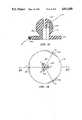
- FIG. 1illustrates an embodiment with the mounting arrangement internally disposed relative to an operator's hand grip.
- Three pairs of leaf-spring elements 10A, 10B and 10Care attached to a metal base 8 and extend in three mutually perpendicular planes; the center lines of the leaf-spring elements intersect at the centre of the base 8, and extend respectively along X, Y and Z axes.
- each leaf-spring element 10A, 10B and 10Care substantially of the same length and each leaf-spring element has at the end distant from the base 8, a ball-like tip 11A, 11B and 11C which lies within a respective slot 12A, 12B and 12C in a hand grip 9 represented by a frame.
- Each slotprovides constraint of the corresponding tip against movement relative to the grip in a direction perpendicular to the plane of the corresponding leaf spring.
- a displacement force applied to the grip 9 along the Z axiscauses bending of the leaf-springs 10B only and strain gauges (not shown) measure the bending so that a signal corresponding to the displacement force can be produced.
- Each tiphas a freedom of motion relative to the grip 9 in the plane of the corresponding leaf-spring.
- a displacement force at an angle to each of the axesis resolved into corresponding bending components in all leaf-spring elements.
- a torque applied to the hand gripis resolved into corresponding couples about the respective X, Y and Z axes.
- torque about the Z axiscauses equal and opposite bending of the leaf-springs 10A as the respective tips are deflected.
- F Irepresents a force in the I direction
- T Irepresents a torque about the I axis
- R1 to R6represent relative displacements in the directions indicated.
- each of the X, Y and Z leaf-spring elementsconsists of a pair of flat resilient metal strips spaced apart and secured by screws 7 to opposite faces of the central cubic mounting block 8 and at their remote ends the strips are interconnected by a connector 13 having screws which also attaches an end fitting 14.
- the end fitting 14has an axially extending shaft terminating in the ball like tip 11A, 11B or 11C.
- the optical detector associated with each leaf-springcomprises a light emitting diode (LED) 2 and a photodiode 3 fixedly mounted on a bracket 4.
- LEDlight emitting diode
- Each bracketis mounted on a respective mounting bar 6 secured by screws 7 to the central block 8, with a packing block 6A and the central part of the leaf-spring element being sandwiched between the mounting bar 6 and the central block 8.
- a shutter 5is attached to the end fitting 14 (which interconnects the leaf-spring metal strips) and thus movement of the shutter alters the extent to which the radiation of the LED 2 can fall on the photodiode 3. Thus displacement is determined by alteration of current in electrical circuitry.
- Each photodiodeis connected through wiring for electronic circuitry where the necessary computation of force and torque takes place.
- a hand grip 30is represented by a mounting ball 31 to which shafts 31A, 31B and 31C are affixed.
- the hand grip 30is mounted through a set of three L-shaped mounting structures pivotally mounted on the respective mutually perpendicular shafts.
- the mounting structurescomprise V-shaped arm members 33A, 33B and 33C and respective leg members 32A, 32B and 32C which connect the hand grip 30 to a base 34.
- Each of the arm members 33A, 33B and 33Cis V-shaped and hingably connected to the corresponding shafts 31A, 31B and 31C for pivotal motion respectively about the X, Z and Y axes.
- Each of the arm membersis connected to a respective leg member 32A, 32B and 32C through a ball joint 35 which provides a limited range of universal relative motion.
- the base of each leg memberis fixed to the base 34 and includes a narrow portion 36 near the base to provide a region of preferential bending.
- Each legis of a spring metal material and has inherent resilience biasing the leg to the position shown in the drawing.
- a force and or torque applied to the grip 30results, in the general case, in a displacement of each of the respective arm-leg member connections and in particular displacement at the respective ball joints is detected.
- a detection plate assemblywould be mounted near each ball joint to enable accurate measurements of deflection in a substantially planar surface perpendicular to the axis of the respective leg 32A, 32B or 32C. It can be shown that the force and torque components applied to the grip can be calculated from the respective displacements by the following equations:
- R1 to R6represent the relative displacements of each respective ball joint as shown in the drawing.
- FIG. 4The schematic diagram shown in FIG. 4 is useful for understanding the principles behind the operation of the second embodiment: however, a construction as shown in FIGS. 5 and 6 is a practical embodiment.
- FIG. 5an X-Z plane is shown with the Y axis perpendicular to the plane of the paper.
- the apparatushas corresponding construction and function when considered in either of the other two perpendicular planes.
- FIGS. 5 and 6the same reference numerals have been used for the parts corresponding to the structure shown in FIG. 4.
- FIG. 5is an axial section through the ball-like grip 30 which is adapted to fit comfortably in the operator's hand.
- the hinges represented by the mounting shafts 31A, 31B, 31C of FIG. 4are replaced by respective cranked cross-shafts 31A, 31B and 31C which extend from just one side of the ball grip 30 and comprise part of the respective arms 33A, 33B and 33C.
- the cranked profile of each shaftis to permit the three mutually perpendicular shafts to pass diametrically through the ball and to cross over one another thereby permitting the shafts to be rotatably mounted at each end at bearing points 40 within the ball grip.
- the free end of each shaftis secured by a screw 45 and washer 44, a part spherical cap 46 being secured over the free end of the shaft by screws 43.
- Each ball joint 35comprises a part spherical ball member 35A mounted on the leg 32A, 32B and 32C with a corresponding tip element 35B (with a part-spherical cavity) mounted on the end of the respective arms 33A, 33B and 33C.
- a screw threaded extension 35Cextends beyond the ball joint from the leg and the ball joint is assembled by a first securing nut 38.
- a sensor assembly 39is then fixed on the screw threaded extension and secured in place by a second nut 41.
- the sensor plate assembly 39 mounted on the end of arm 33Bextends generally in the X-Z plane.
- the sensor plate 39is of opaque material and is adapted to interrupt to a variable and partial extent the passage of light from light sources 42 which are directed towards light dependent resistors 47.
- FIG. 7 to 9show a preferred and alternative mounting arrangement for the respective legs of the embodiment of FIGS. 4 to 6.
- One mounting unitis shown in each of FIGS. 7 to 9 and has the general feature of providing true displacement in a plane, whereas in the arrangement of FIGS. 4 to 6 the displacement is in a very small arc of a sphere and is thus not true planar motion and very small errors are introduced into the results obtained.
- FIGS. 7 to 9the parts for mounting the ball grip corresponding to leg-arm combination 32A, 33A are shown; like reference numerals are used for like parts.
- a rigid base plate 34is adapted to be fixed to a rigid mount so as not to move in space.
- the mounting arm 33Ais pivotally connected to the hand grip (not shown) and is connected to the base plate 34 through a resiliently displaceable mounting leg arrangement; the arm has a ball joint including a ball 35A extending from the arm 33A and engaged in a seat of the mounting leg arrangement.
- This leg arrangementcomprises a generally pear-shaped rigid plate 32A providing a seat for the ball 35A, a first set of spring legs 36A, a rigid connecting disk 36B and secondary spring legs 36C extending parallel to the first set of legs and connected to the base 34.
- the respective sets of legsare alternately spaced equally around a circular path and thou form essentially a complex spring structure.
- any motion of the mounting arm 33A in a plane parallel to the plate 32Acauses the three spring legs 36A to be bent resiliently into a shallow S-shape, reaction occurs through the disk 36B, and the secondary legs 36C bend resiliently into a corresponding S-shape bent in the opposite direction.
- an applied force to the hand grip 30 causing displacement of the arm 33A in the relevant planecauses motion of the plate 32A and thus motion of an attached shutter 39 in a parallel plane thereto.
- Displacementis detected by the degree of interruption of a light source (not shown) inpinging on photodiodes 47.
- the shutter 39has operating edges 39a and 39b extending at right angles so that displacement in the plane is resolved in two components.
- the shutteris mounted on a mounting shaft 39c extending from the pear-shaped plate 32A through an aperture in the rigid base 34, the rigid base carrying the photodiodes.
- FIG. 7shows most clearly respective bosses 36D through which the resilient legs 36A extend, these bosses extending into respective apertures in the base 34. Any excessive movement of the arm 33A causes one or more of the bosses to abut the wall of the corresponding aperture thereby providing a limit to movement.
- FIGS. 4 to 6An alternative and advantageous embodiment is a variation on that of FIGS. 4 to 6 and wherein the mounting arm is formed as shown in FIGS. 10 and 11 and the hand grip is as formed in FIGS. 12 and 13.
- the operating principlesare the same, but the construction has advantages.
- the mounting arm referenced 33Ahas a generally Y-shaped physical form having respective ends 50, 51 and 52.
- End 50has, extending laterally therefrom, the ball 35A for connection to the mounting leg (or plate 32A as shown in FIG. 9).
- End 51terminates in a sleeve like tip 51a with an aperture extending therethrough (along the X axis) and aligned with a small bore extending obliquely through the tip region of the arm 52.
- the hand grip shown in FIGS. 12 and 13is of plastics material and has a spherical ball-shaped head and a circular base plate 30a, and is adapted to be connected to a set of three arms of the type shown in FIGS. 10 and 11.
- the base plate 30ahas a series of three spaced inclined bores 30b extending from chamfered surfaces and respectively along X, Y and Z axes of the apparatus.
- a series of three axially aligned corresponding bores 30care provided in the top portion of the spherical head.
- FIG. 12shows a section along the X axis.
- the mounting armhas a limited freedom to rotate about the X axis at its connection with the ball-shaped head and freedom about the Z-axis at its connection with the mounting leg arrangement, as conceptually shown in FIG. 4. Therefore, any displacement force on the ball-shaped head and along the X axis or a torque about the X axis results in no displacement of mounting leg 32A associated with arm 33A but in either case the other mounting legs may be displaced and thus the motion detected.
- the ball-shaped headincludes a central interior bore 30e for clearance purposes for the respective arm ends 52.
- the inventioncan be applied to the control of an industrial robot, whereby pushing and twisting motions of the operator's hand on the grip 30 causes corresponding motions at the respective sensor plate assembly and by computation in accordance with the above equations the applied forces and torques can be determined. This permits corresponding motion to be controlled in the robot.
- a further advantageous application of the present inventionin general, exploits the ability of embodiments of the invention to detect and measure force and/or torque applied relative to two parts.
- An illustrative exampleis the case of a connection between two aircraft flying in formation and connected by a refueling device.
- the inventioncould be incorporated in a coupling whereby the relative applied translational forces and torques between the two aircraft are detected and monitored and indeed in a sophisticated application this might cause the control systems of the aircraft to automatically compensate as may be necessary to keep the applied forces and torques within allowable ranges.
Landscapes
- Engineering & Computer Science (AREA)
- Physics & Mathematics (AREA)
- General Physics & Mathematics (AREA)
- Robotics (AREA)
- Mechanical Engineering (AREA)
- Human Computer Interaction (AREA)
- Force Measurement Appropriate To Specific Purposes (AREA)
- Mechanical Control Devices (AREA)
Abstract
Description
F.sub.X =R1+R2
F.sub.Y =R3+R4
F.sub.Z =R5+R6
T.sub.X =R5-R6
T.sub.Y =R1-R2
T.sub.Z =R3-R4
F.sub.X =R1+R2
F.sub.Y =R3+R4
F.sub.Z =R5+R6
T.sub.X =-R3
T.sub.Y =-R5
T.sub.Z =-R1
Claims (18)
Priority Applications (3)
| Application Number | Priority Date | Filing Date | Title |
|---|---|---|---|
| US07/427,931US5222400A (en) | 1985-12-18 | 1989-10-25 | Force and torque converter |
| US08/052,377US5591924A (en) | 1985-12-18 | 1993-04-23 | Force and torque converter |
| US08/475,660US5706027A (en) | 1985-12-18 | 1995-06-07 | Force and torque converter for use in a computer input device |
Applications Claiming Priority (2)
| Application Number | Priority Date | Filing Date | Title |
|---|---|---|---|
| AUPH393485 | 1985-12-18 | ||
| AUPH03934 | 1985-12-18 |
Related Child Applications (1)
| Application Number | Title | Priority Date | Filing Date |
|---|---|---|---|
| US31111389AContinuation | 1985-12-18 | 1989-02-15 |
Publications (1)
| Publication Number | Publication Date |
|---|---|
| US4811608Atrue US4811608A (en) | 1989-03-14 |
Family
ID=3771414
Family Applications (1)
| Application Number | Title | Priority Date | Filing Date |
|---|---|---|---|
| US06/927,915Expired - LifetimeUS4811608A (en) | 1985-12-18 | 1986-11-06 | Force and torque converter |
Country Status (3)
| Country | Link |
|---|---|
| US (1) | US4811608A (en) |
| JP (1) | JPS62177426A (en) |
| DE (1) | DE3687571D1 (en) |
Cited By (97)
| Publication number | Priority date | Publication date | Assignee | Title |
|---|---|---|---|---|
| US5279176A (en)* | 1992-07-20 | 1994-01-18 | The United States Of America As Represented By The Administrator Of The National Aeronautics And Space Administration | Six-degree-of-freedom parallel "minimanipulator" with three inextensible limbs |
| US5335557A (en)* | 1991-11-26 | 1994-08-09 | Taizo Yasutake | Touch sensitive input control device |
| US5589828A (en)* | 1992-03-05 | 1996-12-31 | Armstrong; Brad A. | 6 Degrees of freedom controller with capability of tactile feedback |
| US5691898A (en)* | 1995-09-27 | 1997-11-25 | Immersion Human Interface Corp. | Safe and low cost computer peripherals with force feedback for consumer applications |
| US5701140A (en)* | 1993-07-16 | 1997-12-23 | Immersion Human Interface Corp. | Method and apparatus for providing a cursor control interface with force feedback |
| US5706027A (en)* | 1985-12-18 | 1998-01-06 | Spacetec Imc Corporation | Force and torque converter for use in a computer input device |
| US5721566A (en)* | 1995-01-18 | 1998-02-24 | Immersion Human Interface Corp. | Method and apparatus for providing damping force feedback |
| US5724264A (en)* | 1993-07-16 | 1998-03-03 | Immersion Human Interface Corp. | Method and apparatus for tracking the position and orientation of a stylus and for digitizing a 3-D object |
| US5731804A (en)* | 1995-01-18 | 1998-03-24 | Immersion Human Interface Corp. | Method and apparatus for providing high bandwidth, low noise mechanical I/O for computer systems |
| US5734373A (en)* | 1993-07-16 | 1998-03-31 | Immersion Human Interface Corporation | Method and apparatus for controlling force feedback interface systems utilizing a host computer |
| US5739811A (en)* | 1993-07-16 | 1998-04-14 | Immersion Human Interface Corporation | Method and apparatus for controlling human-computer interface systems providing force feedback |
| US5751275A (en)* | 1994-11-14 | 1998-05-12 | Bullister; Edward T. | Two-- and three--dimensional trackball with coordinate transformations |
| WO1998025193A1 (en) | 1996-12-04 | 1998-06-11 | Martin Sundin | Position measuring device for detecting displacements with at least three degrees of freedom |
| US5767839A (en)* | 1995-01-18 | 1998-06-16 | Immersion Human Interface Corporation | Method and apparatus for providing passive force feedback to human-computer interface systems |
| US5805140A (en)* | 1993-07-16 | 1998-09-08 | Immersion Corporation | High bandwidth force feedback interface using voice coils and flexures |
| US5821920A (en)* | 1994-07-14 | 1998-10-13 | Immersion Human Interface Corporation | Control input device for interfacing an elongated flexible object with a computer system |
| US5825308A (en)* | 1996-11-26 | 1998-10-20 | Immersion Human Interface Corporation | Force feedback interface having isotonic and isometric functionality |
| US5828197A (en)* | 1996-10-25 | 1998-10-27 | Immersion Human Interface Corporation | Mechanical interface having multiple grounded actuators |
| US5847528A (en)* | 1995-05-19 | 1998-12-08 | Canadian Space Agency | Mechanism for control of position and orientation in three dimensions |
| US5854623A (en)* | 1994-11-14 | 1998-12-29 | Bullister; Edward T. | Two- and three-dimensional trackball with enhanced measurement optics |
| US5889505A (en)* | 1996-04-04 | 1999-03-30 | Yale University | Vision-based six-degree-of-freedom computer input device |
| US5936165A (en)* | 1997-02-18 | 1999-08-10 | Hughes Electronics Corporation | Methods for uniform heating and cooling of large objects |
| US5956484A (en)* | 1995-12-13 | 1999-09-21 | Immersion Corporation | Method and apparatus for providing force feedback over a computer network |
| US6020875A (en)* | 1997-10-31 | 2000-02-01 | Immersion Corporation | High fidelity mechanical transmission system and interface device |
| US6028593A (en)* | 1995-12-01 | 2000-02-22 | Immersion Corporation | Method and apparatus for providing simulated physical interactions within computer generated environments |
| US6037927A (en)* | 1994-07-14 | 2000-03-14 | Immersion Corporation | Method and apparatus for providing force feedback to the user of an interactive computer simulation |
| US6061004A (en)* | 1995-11-26 | 2000-05-09 | Immersion Corporation | Providing force feedback using an interface device including an indexing function |
| US6067077A (en)* | 1998-04-10 | 2000-05-23 | Immersion Corporation | Position sensing for force feedback devices |
| US6100874A (en)* | 1995-11-17 | 2000-08-08 | Immersion Corporation | Force feedback mouse interface |
| US6104382A (en)* | 1997-10-31 | 2000-08-15 | Immersion Corporation | Force feedback transmission mechanisms |
| US6125385A (en)* | 1996-08-01 | 2000-09-26 | Immersion Corporation | Force feedback implementation in web pages |
| US6161126A (en)* | 1995-12-13 | 2000-12-12 | Immersion Corporation | Implementing force feedback over the World Wide Web and other computer networks |
| US6166723A (en)* | 1995-11-17 | 2000-12-26 | Immersion Corporation | Mouse interface device providing force feedback |
| US6208349B1 (en)* | 1997-04-14 | 2001-03-27 | Sandia Corporation | Multidimensional display controller for displaying to a user an aspect of a multidimensional space visible from a base viewing location along a desired viewing orientation |
| US6219032B1 (en) | 1995-12-01 | 2001-04-17 | Immersion Corporation | Method for providing force feedback to a user of an interface device based on interactions of a controlled cursor with graphical elements in a graphical user interface |
| US6281651B1 (en) | 1997-11-03 | 2001-08-28 | Immersion Corporation | Haptic pointing devices |
| US20020000971A1 (en)* | 1992-03-05 | 2002-01-03 | Armstrong Brad A. | Image controller |
| USRE37528E1 (en) | 1994-11-03 | 2002-01-22 | Immersion Corporation | Direct-drive manipulator for pen-based force display |
| US20020019259A1 (en)* | 1997-10-01 | 2002-02-14 | Armstrong Brad A. | Controller with analog pressure sensor (s) |
| US20020050978A1 (en)* | 1995-12-13 | 2002-05-02 | Immersion Corporation | Force feedback applications based on cursor engagement with graphical targets |
| US6400352B1 (en) | 1995-01-18 | 2002-06-04 | Immersion Corporation | Mechanical and force transmission for force feedback devices |
| US6417836B1 (en) | 1999-08-02 | 2002-07-09 | Lucent Technologies Inc. | Computer input device having six degrees of freedom for controlling movement of a three-dimensional object |
| US6437771B1 (en) | 1995-01-18 | 2002-08-20 | Immersion Corporation | Force feedback device including flexure member between actuator and user object |
| US6456778B2 (en) | 1997-10-01 | 2002-09-24 | Brad A. Armstrong | Analog controls housed with electronic displays for video recorders and cameras |
| US6593912B1 (en) | 2000-03-21 | 2003-07-15 | International Business Machines Corporation | Electro-mechanical transducer for six degrees of freedom input and output |
| US6597347B1 (en) | 1991-11-26 | 2003-07-22 | Itu Research Inc. | Methods and apparatus for providing touch-sensitive input in multiple degrees of freedom |
| WO2002035457A3 (en)* | 2000-10-27 | 2003-09-18 | Makex Ltd | Haptic input device |
| US6639581B1 (en) | 1995-11-17 | 2003-10-28 | Immersion Corporation | Flexure mechanism for interface device |
| US20030201869A1 (en)* | 1996-07-05 | 2003-10-30 | Armstrong Brad A. | Analog sensor(s) with tactile feedback |
| US6670947B2 (en)* | 2001-10-22 | 2003-12-30 | Robert William Smyth | SO3 input device |
| US6686911B1 (en) | 1996-11-26 | 2004-02-03 | Immersion Corporation | Control knob with control modes and force feedback |
| US6697748B1 (en) | 1995-08-07 | 2004-02-24 | Immersion Corporation | Digitizing system and rotary table for determining 3-D geometry of an object |
| US6705871B1 (en) | 1996-09-06 | 2004-03-16 | Immersion Corporation | Method and apparatus for providing an interface mechanism for a computer simulation |
| US20040160414A1 (en)* | 1996-07-05 | 2004-08-19 | Armstrong Brad A. | Image controller |
| US20040160415A1 (en)* | 1995-12-01 | 2004-08-19 | Rosenberg Louis B. | Designing force sensations for force feedback computer applications |
| US6781569B1 (en) | 1999-06-11 | 2004-08-24 | Immersion Corporation | Hand controller |
| US20040227727A1 (en)* | 1995-11-17 | 2004-11-18 | Schena Bruce M. | Force feedback device including actuator with moving magnet |
| US20040243724A1 (en)* | 2001-09-21 | 2004-12-02 | Bernd Gombert | Combined position and torque sensor |
| US20050017454A1 (en)* | 2003-06-09 | 2005-01-27 | Shoichi Endo | Interactive gaming systems with haptic feedback |
| US6850222B1 (en) | 1995-01-18 | 2005-02-01 | Immersion Corporation | Passive force feedback for computer interface devices |
| US6859819B1 (en) | 1995-12-13 | 2005-02-22 | Immersion Corporation | Force feedback enabled over a computer network |
| US6906700B1 (en) | 1992-03-05 | 2005-06-14 | Anascape | 3D controller with vibration |
| US20050162389A1 (en)* | 2002-04-12 | 2005-07-28 | Obermeyer Henry K. | Multi-axis joystick and transducer means therefore |
| US20050162804A1 (en)* | 2001-06-27 | 2005-07-28 | Boronkay Allen R. | Position sensor with resistive element |
| US20050231476A1 (en)* | 1996-07-05 | 2005-10-20 | Armstrong Brad A | Image controller |
| US6979164B2 (en) | 1990-02-02 | 2005-12-27 | Immersion Corporation | Force feedback and texture simulating interface device |
| US20060050051A1 (en)* | 2002-10-28 | 2006-03-09 | Hilton John A | Three-dimensional force and torque converter |
| US20060082546A1 (en)* | 2003-06-23 | 2006-04-20 | Fun Wey | Computer input device tracking six degrees of freedom |
| US7039866B1 (en) | 1995-12-01 | 2006-05-02 | Immersion Corporation | Method and apparatus for providing dynamic force sensations for force feedback computer applications |
| US20060192760A1 (en)* | 2000-09-28 | 2006-08-31 | Immersion Corporation | Actuator for providing tactile sensations and device for directional tactile sensations |
| US7113166B1 (en) | 1995-06-09 | 2006-09-26 | Immersion Corporation | Force feedback devices using fluid braking |
| US20060267949A1 (en)* | 1999-12-07 | 2006-11-30 | Rosenberg Louis B | Haptic feedback using a keyboard device |
| US20060283279A1 (en)* | 2002-04-03 | 2006-12-21 | Levin Michael D | Haptic control devices |
| US20060283280A1 (en)* | 2005-04-26 | 2006-12-21 | Still Gmbh | Industrial truck with a multi-function lever |
| US20070039400A1 (en)* | 2003-12-04 | 2007-02-22 | Mts Systems Corporation | Platform balance |
| US20070052674A1 (en)* | 1997-12-03 | 2007-03-08 | Culver Craig F | Tactile feedback interface device including display screen |
| US7209117B2 (en) | 1995-12-01 | 2007-04-24 | Immersion Corporation | Method and apparatus for streaming force values to a force feedback device |
| US20070130212A1 (en)* | 1996-05-21 | 2007-06-07 | Peurach Thomas M | Haptic authoring |
| US20070152988A1 (en)* | 1996-11-26 | 2007-07-05 | Levin Michael D | Control knob with multiple degrees of freedom and force feedback |
| US20070252501A1 (en)* | 2004-02-03 | 2007-11-01 | Federal-Mogul Ignition (U.K.) Limited | Spark plug configuration having a metal noble tip |
| US7373587B1 (en) | 1990-06-25 | 2008-05-13 | Barstow David R | Representing sub-events with physical exertion actions |
| US20080264183A1 (en)* | 2004-08-09 | 2008-10-30 | Ci3 Limited | Full-Axis Sensor for Detecting Input Force and Torque |
| USRE40891E1 (en) | 1991-11-26 | 2009-09-01 | Sandio Technology Corp. | Methods and apparatus for providing touch-sensitive input in multiple degrees of freedom |
| US20100305928A1 (en)* | 2009-05-28 | 2010-12-02 | Immersion Corporation | Systems and Methods For Editing A Model Of A Physical System For A Simulation |
| US20110043474A1 (en)* | 2005-05-12 | 2011-02-24 | Immersion Corporation | Method And Apparatus For Providing Haptic Effects To A Touch Panel |
| US20110247446A1 (en)* | 2010-04-08 | 2011-10-13 | Bia | Hexapod Platform and Jack That Can be Used in the Hexapod Platform |
| US8157650B2 (en) | 2006-09-13 | 2012-04-17 | Immersion Corporation | Systems and methods for casino gaming haptics |
| US8199107B2 (en) | 2004-12-22 | 2012-06-12 | University Of Waterloo | Input interface device with transformable form factor |
| DE102011106894B3 (en)* | 2011-07-07 | 2012-07-19 | Technische Universität Ilmenau | Apparatus for simultaneous measurement of force and moment components, has deformable element that is provided with rod-shaped movable elements with bending joints and edges in cuboid form |
| US8508469B1 (en) | 1995-12-01 | 2013-08-13 | Immersion Corporation | Networked applications including haptic feedback |
| US8917234B2 (en) | 2002-10-15 | 2014-12-23 | Immersion Corporation | Products and processes for providing force sensations in a user interface |
| US9486292B2 (en) | 2008-02-14 | 2016-11-08 | Immersion Corporation | Systems and methods for real-time winding analysis for knot detection |
| US9778122B2 (en) | 2013-08-01 | 2017-10-03 | Mts Systems Corporation | Two-axis sensor body for a load transducer |
| US9866924B2 (en) | 2013-03-14 | 2018-01-09 | Immersion Corporation | Systems and methods for enhanced television interaction |
| CN110199239A (en)* | 2016-11-28 | 2019-09-03 | M·A·格里芬 | Remote control of equipment and systems |
| US10591373B2 (en) | 2013-08-01 | 2020-03-17 | Mts Systems Corporation | Load transducer having a biasing assembly |
| CN118670579A (en)* | 2024-07-19 | 2024-09-20 | 华能煤炭技术研究有限公司 | Three-dimensional tension real-time monitoring device based on optical fiber sensing and working method thereof |
Families Citing this family (2)
| Publication number | Priority date | Publication date | Assignee | Title |
|---|---|---|---|---|
| US6564626B2 (en)* | 1999-11-26 | 2003-05-20 | The Boeing Company | Apparatus and method for measuring forces and moments acting on models tested in aerodynamic wind tunnels |
| WO2004109661A1 (en)* | 2003-06-05 | 2004-12-16 | Matsushita Electric Industrial Co., Ltd. | Sound quality adjusting apparatus and sound quality adjusting method |
Citations (15)
| Publication number | Priority date | Publication date | Assignee | Title |
|---|---|---|---|---|
| DE926213C (en)* | 1951-01-25 | 1955-04-07 | Adriaan Hendrik Couwenhoven | Method and device for automated milking |
| DE957980C (en)* | 1957-01-24 | LICENTIA Patent - Verwaltungs-GmbH, Hamburg | Device for measuring orthogonal force and torque components | |
| US3628394A (en)* | 1970-02-09 | 1971-12-21 | Sperry Rand Corp | Operator-manipulative control apparatus |
| US3921445A (en)* | 1973-10-15 | 1975-11-25 | Stanford Research Inst | Force and torque sensing method and means for manipulators and the like |
| US4178799A (en)* | 1977-06-21 | 1979-12-18 | Deutsch Forschungs- Und Versuchsanstalt Fur Luft- Und Raumfahrt E.V. | Force and bending moment sensing arrangement and structure |
| GB2096777A (en)* | 1981-04-13 | 1982-10-20 | Yamato Scale Co Ltd | Measuring components of force and moment |
| SU974155A1 (en)* | 1981-05-13 | 1982-11-15 | Государственный Научно-Исследовательский Институт Машиноведения Им.А.А.Благонравова | Force and moment vector pickup |
| DD209519A1 (en)* | 1982-09-14 | 1984-05-09 | Koerperkultur Sport Forsch | PLATFORM FOR MEASURING SEVERAL ORTHOGONAL POWER COMPONENTS |
| US4488441A (en)* | 1983-04-15 | 1984-12-18 | Jr3, Inc. | Apparatus for simultaneous measurement of mutually perpendicular forces and moments |
| DD218458A1 (en)* | 1983-08-04 | 1985-02-06 | Ilmenau Tech Hochschule | POWER-TORQUE-PROBE |
| DD224930A1 (en)* | 1984-06-28 | 1985-07-17 | Techn Hochschule Ilmenau | POWER-TORQUE-PROBE |
| DE3420884A1 (en)* | 1984-06-05 | 1986-01-23 | Dahms, Joachim | Force/torque sensor |
| US4573362A (en)* | 1984-07-09 | 1986-03-04 | Eaton Corporation | Multi-axis load transducer |
| EP0176173A2 (en)* | 1984-09-27 | 1986-04-02 | Kabushiki Kaisha Toshiba | Sensor for sensing three orthogonal forces and three orthogonal moments |
| US4607159A (en)* | 1983-12-27 | 1986-08-19 | North American Philips Consumer Electronics Corp. | Optical joystick controller with intersecting spring means |
- 1986
- 1986-11-06USUS06/927,915patent/US4811608A/ennot_activeExpired - Lifetime
- 1986-12-16JPJP61301109Apatent/JPS62177426A/enactiveGranted
- 1986-12-17DEDE8686309878Tpatent/DE3687571D1/ennot_activeExpired - Fee Related
Patent Citations (15)
| Publication number | Priority date | Publication date | Assignee | Title |
|---|---|---|---|---|
| DE957980C (en)* | 1957-01-24 | LICENTIA Patent - Verwaltungs-GmbH, Hamburg | Device for measuring orthogonal force and torque components | |
| DE926213C (en)* | 1951-01-25 | 1955-04-07 | Adriaan Hendrik Couwenhoven | Method and device for automated milking |
| US3628394A (en)* | 1970-02-09 | 1971-12-21 | Sperry Rand Corp | Operator-manipulative control apparatus |
| US3921445A (en)* | 1973-10-15 | 1975-11-25 | Stanford Research Inst | Force and torque sensing method and means for manipulators and the like |
| US4178799A (en)* | 1977-06-21 | 1979-12-18 | Deutsch Forschungs- Und Versuchsanstalt Fur Luft- Und Raumfahrt E.V. | Force and bending moment sensing arrangement and structure |
| GB2096777A (en)* | 1981-04-13 | 1982-10-20 | Yamato Scale Co Ltd | Measuring components of force and moment |
| SU974155A1 (en)* | 1981-05-13 | 1982-11-15 | Государственный Научно-Исследовательский Институт Машиноведения Им.А.А.Благонравова | Force and moment vector pickup |
| DD209519A1 (en)* | 1982-09-14 | 1984-05-09 | Koerperkultur Sport Forsch | PLATFORM FOR MEASURING SEVERAL ORTHOGONAL POWER COMPONENTS |
| US4488441A (en)* | 1983-04-15 | 1984-12-18 | Jr3, Inc. | Apparatus for simultaneous measurement of mutually perpendicular forces and moments |
| DD218458A1 (en)* | 1983-08-04 | 1985-02-06 | Ilmenau Tech Hochschule | POWER-TORQUE-PROBE |
| US4607159A (en)* | 1983-12-27 | 1986-08-19 | North American Philips Consumer Electronics Corp. | Optical joystick controller with intersecting spring means |
| DE3420884A1 (en)* | 1984-06-05 | 1986-01-23 | Dahms, Joachim | Force/torque sensor |
| DD224930A1 (en)* | 1984-06-28 | 1985-07-17 | Techn Hochschule Ilmenau | POWER-TORQUE-PROBE |
| US4573362A (en)* | 1984-07-09 | 1986-03-04 | Eaton Corporation | Multi-axis load transducer |
| EP0176173A2 (en)* | 1984-09-27 | 1986-04-02 | Kabushiki Kaisha Toshiba | Sensor for sensing three orthogonal forces and three orthogonal moments |
Non-Patent Citations (2)
| Title |
|---|
| Grigg et al., "Wheel Force Transducer", in Engineering Conf. on Stress and Strain-Aug. 1973-pp. 170-175. |
| Grigg et al., Wheel Force Transducer , in Engineering Conf. on Stress and Strain Aug. 1973 pp. 170 175.* |
Cited By (202)
| Publication number | Priority date | Publication date | Assignee | Title |
|---|---|---|---|---|
| US5706027A (en)* | 1985-12-18 | 1998-01-06 | Spacetec Imc Corporation | Force and torque converter for use in a computer input device |
| US6979164B2 (en) | 1990-02-02 | 2005-12-27 | Immersion Corporation | Force feedback and texture simulating interface device |
| US20080209307A1 (en)* | 1990-06-25 | 2008-08-28 | Barstow David R | Representing sub-event with physical exertion actions |
| US7373587B1 (en) | 1990-06-25 | 2008-05-13 | Barstow David R | Representing sub-events with physical exertion actions |
| US5729249A (en)* | 1991-11-26 | 1998-03-17 | Itu Research, Inc. | Touch sensitive input control device |
| US5805137A (en)* | 1991-11-26 | 1998-09-08 | Itu Research, Inc. | Touch sensitive input control device |
| US5335557A (en)* | 1991-11-26 | 1994-08-09 | Taizo Yasutake | Touch sensitive input control device |
| US6597347B1 (en) | 1991-11-26 | 2003-07-22 | Itu Research Inc. | Methods and apparatus for providing touch-sensitive input in multiple degrees of freedom |
| USRE40891E1 (en) | 1991-11-26 | 2009-09-01 | Sandio Technology Corp. | Methods and apparatus for providing touch-sensitive input in multiple degrees of freedom |
| US20060022939A1 (en)* | 1992-03-05 | 2006-02-02 | Armstrong Brad A | Image controller |
| US5589828A (en)* | 1992-03-05 | 1996-12-31 | Armstrong; Brad A. | 6 Degrees of freedom controller with capability of tactile feedback |
| US20060022941A1 (en)* | 1992-03-05 | 2006-02-02 | Armstrong Brad A | Image controller |
| US6906700B1 (en) | 1992-03-05 | 2005-06-14 | Anascape | 3D controller with vibration |
| US7345670B2 (en) | 1992-03-05 | 2008-03-18 | Anascape | Image controller |
| US20020000971A1 (en)* | 1992-03-05 | 2002-01-03 | Armstrong Brad A. | Image controller |
| US20060028441A1 (en)* | 1992-03-05 | 2006-02-09 | Armstrong Brad A | Image controller |
| US20060028438A1 (en)* | 1992-03-05 | 2006-02-09 | Armstrong Brad A | Image controller |
| US9081426B2 (en) | 1992-03-05 | 2015-07-14 | Anascape, Ltd. | Image controller |
| US5301566A (en)* | 1992-07-20 | 1994-04-12 | The United States Of America As Represented By The Administrator Of The National Aeronautics & Space Administration | Simplified and symmetrical five-bar linkage driver for manipulating a Six-Degree-of-Freedom Parallel "minimanipulator" with three inextensible limbs |
| US5279176A (en)* | 1992-07-20 | 1994-01-18 | The United States Of America As Represented By The Administrator Of The National Aeronautics And Space Administration | Six-degree-of-freedom parallel "minimanipulator" with three inextensible limbs |
| US5739811A (en)* | 1993-07-16 | 1998-04-14 | Immersion Human Interface Corporation | Method and apparatus for controlling human-computer interface systems providing force feedback |
| US5805140A (en)* | 1993-07-16 | 1998-09-08 | Immersion Corporation | High bandwidth force feedback interface using voice coils and flexures |
| US5701140A (en)* | 1993-07-16 | 1997-12-23 | Immersion Human Interface Corp. | Method and apparatus for providing a cursor control interface with force feedback |
| US5880714A (en)* | 1993-07-16 | 1999-03-09 | Immersion Corporation | Three-dimensional cursor control interface with force feedback |
| US7091950B2 (en) | 1993-07-16 | 2006-08-15 | Immersion Corporation | Force feedback device including non-rigid coupling |
| US5929846A (en)* | 1993-07-16 | 1999-07-27 | Immersion Corporation | Force feedback interface device including grounded sensor system |
| US20060176272A1 (en)* | 1993-07-16 | 2006-08-10 | Rosenberg Louis B | Method and apparatus for controlling human-computer interface systems providing force feedback |
| US7061467B2 (en) | 1993-07-16 | 2006-06-13 | Immersion Corporation | Force feedback device with microprocessor receiving low level commands |
| US20020063685A1 (en)* | 1993-07-16 | 2002-05-30 | Immersion Corporation | Interface device for sensing position and orientation and outputting force to a user |
| US20040145563A9 (en)* | 1993-07-16 | 2004-07-29 | Rosenberg Louis B. | Force Feedback Device |
| US20030030621A1 (en)* | 1993-07-16 | 2003-02-13 | Rosenberg Louis B. | Force feeback device including flexure member between actuator and user object |
| US6046727A (en)* | 1993-07-16 | 2000-04-04 | Immersion Corporation | Three dimensional position sensing interface with force output |
| US6125337A (en)* | 1993-07-16 | 2000-09-26 | Microscribe, Llc | Probe apparatus and method for tracking the position and orientation of a stylus and controlling a cursor |
| US5734373A (en)* | 1993-07-16 | 1998-03-31 | Immersion Human Interface Corporation | Method and apparatus for controlling force feedback interface systems utilizing a host computer |
| US6987504B2 (en) | 1993-07-16 | 2006-01-17 | Immersion Corporation | Interface device for sensing position and orientation and outputting force to a user |
| US7605800B2 (en) | 1993-07-16 | 2009-10-20 | Immersion Corporation | Method and apparatus for controlling human-computer interface systems providing force feedback |
| US5724264A (en)* | 1993-07-16 | 1998-03-03 | Immersion Human Interface Corp. | Method and apparatus for tracking the position and orientation of a stylus and for digitizing a 3-D object |
| US20040252100A9 (en)* | 1993-07-16 | 2004-12-16 | Immersion Corporation | Interface device for sensing position and orientation and outputting force to a user |
| US5821920A (en)* | 1994-07-14 | 1998-10-13 | Immersion Human Interface Corporation | Control input device for interfacing an elongated flexible object with a computer system |
| US20040066369A1 (en)* | 1994-07-14 | 2004-04-08 | Rosenberg Louis B. | Physically realistic computer simulation of medical procedures |
| US6654000B2 (en) | 1994-07-14 | 2003-11-25 | Immersion Corporation | Physically realistic computer simulation of medical procedures |
| US8184094B2 (en) | 1994-07-14 | 2012-05-22 | Immersion Corporation | Physically realistic computer simulation of medical procedures |
| US6037927A (en)* | 1994-07-14 | 2000-03-14 | Immersion Corporation | Method and apparatus for providing force feedback to the user of an interactive computer simulation |
| US7215326B2 (en) | 1994-07-14 | 2007-05-08 | Immersion Corporation | Physically realistic computer simulation of medical procedures |
| US6215470B1 (en) | 1994-07-14 | 2001-04-10 | Immersion Corp | User interface device including braking mechanism for interfacing with computer simulations |
| US6323837B1 (en) | 1994-07-14 | 2001-11-27 | Immersion Corporation | Method and apparatus for interfacing an elongated object with a computer system |
| USRE37528E1 (en) | 1994-11-03 | 2002-01-22 | Immersion Corporation | Direct-drive manipulator for pen-based force display |
| US5751275A (en)* | 1994-11-14 | 1998-05-12 | Bullister; Edward T. | Two-- and three--dimensional trackball with coordinate transformations |
| US5854623A (en)* | 1994-11-14 | 1998-12-29 | Bullister; Edward T. | Two- and three-dimensional trackball with enhanced measurement optics |
| US6271828B1 (en) | 1995-01-18 | 2001-08-07 | Immersion Corporation | Force feedback interface devices providing resistance forces using a fluid |
| US7023423B2 (en) | 1995-01-18 | 2006-04-04 | Immersion Corporation | Laparoscopic simulation interface |
| US6154198A (en)* | 1995-01-18 | 2000-11-28 | Immersion Corporation | Force feedback interface apparatus including backlash and for generating feel sensations |
| US5767839A (en)* | 1995-01-18 | 1998-06-16 | Immersion Human Interface Corporation | Method and apparatus for providing passive force feedback to human-computer interface systems |
| US6697048B2 (en) | 1995-01-18 | 2004-02-24 | Immersion Corporation | Computer interface apparatus including linkage having flex |
| US7821496B2 (en) | 1995-01-18 | 2010-10-26 | Immersion Corporation | Computer interface apparatus including linkage having flex |
| US5731804A (en)* | 1995-01-18 | 1998-03-24 | Immersion Human Interface Corp. | Method and apparatus for providing high bandwidth, low noise mechanical I/O for computer systems |
| US6201533B1 (en) | 1995-01-18 | 2001-03-13 | Immersion Corporation | Method and apparatus for applying force in force feedback devices using friction |
| US20020018046A1 (en)* | 1995-01-18 | 2002-02-14 | Immersion Corporation | Laparoscopic simulation interface |
| US5721566A (en)* | 1995-01-18 | 1998-02-24 | Immersion Human Interface Corp. | Method and apparatus for providing damping force feedback |
| US6437771B1 (en) | 1995-01-18 | 2002-08-20 | Immersion Corporation | Force feedback device including flexure member between actuator and user object |
| US6246390B1 (en) | 1995-01-18 | 2001-06-12 | Immersion Corporation | Multiple degree-of-freedom mechanical interface to a computer system |
| US6850222B1 (en) | 1995-01-18 | 2005-02-01 | Immersion Corporation | Passive force feedback for computer interface devices |
| US6400352B1 (en) | 1995-01-18 | 2002-06-04 | Immersion Corporation | Mechanical and force transmission for force feedback devices |
| US20040164959A1 (en)* | 1995-01-18 | 2004-08-26 | Rosenberg Louis B. | Computer interface apparatus including linkage having flex |
| US20060050056A1 (en)* | 1995-02-23 | 2006-03-09 | Armstrong Brad A | Image controller |
| US20060038777A1 (en)* | 1995-02-23 | 2006-02-23 | Armstrong Brad A | Image controller |
| US20060022940A1 (en)* | 1995-02-23 | 2006-02-02 | Armstrong Brad A | Image controller |
| US20060028440A1 (en)* | 1995-02-23 | 2006-02-09 | Armstrong Brad A | Image controller |
| US20060033709A1 (en)* | 1995-02-23 | 2006-02-16 | Armstrong Brad A | Image controller |
| US20060028439A1 (en)* | 1995-02-23 | 2006-02-09 | Armstrong Brad A | Image controller |
| US20060028434A1 (en)* | 1995-02-23 | 2006-02-09 | Armstrong Brad A | Image controller |
| US20060033708A1 (en)* | 1995-02-23 | 2006-02-16 | Armstrong Brad A | Image controller |
| US5847528A (en)* | 1995-05-19 | 1998-12-08 | Canadian Space Agency | Mechanism for control of position and orientation in three dimensions |
| US7113166B1 (en) | 1995-06-09 | 2006-09-26 | Immersion Corporation | Force feedback devices using fluid braking |
| US6486872B2 (en) | 1995-06-09 | 2002-11-26 | Immersion Corporation | Method and apparatus for providing passive fluid force feedback |
| US6697748B1 (en) | 1995-08-07 | 2004-02-24 | Immersion Corporation | Digitizing system and rotary table for determining 3-D geometry of an object |
| US6078876A (en)* | 1995-08-07 | 2000-06-20 | Microscribe, Llc | Method and apparatus for tracking the position and orientation of a stylus and for digitizing a 3-D object |
| US6134506A (en)* | 1995-08-07 | 2000-10-17 | Microscribe Llc | Method and apparatus for tracking the position and orientation of a stylus and for digitizing a 3-D object |
| US7054775B2 (en) | 1995-08-07 | 2006-05-30 | Immersion Corporation | Digitizing system and rotary table for determining 3-D geometry of an object |
| US20040162700A1 (en)* | 1995-08-07 | 2004-08-19 | Rosenberg Louis B. | Digitizing system and rotary table for determining 3-D geometry of an object |
| US20020126091A1 (en)* | 1995-09-27 | 2002-09-12 | Immersion Corporation | Power management for interface devices applying forces |
| US20090033624A1 (en)* | 1995-09-27 | 2009-02-05 | Immersion Corporation | Safe and low cost computer peripherals with force feedback for consumer applications |
| US7038657B2 (en) | 1995-09-27 | 2006-05-02 | Immersion Corporation | Power management for interface devices applying forces |
| US5691898A (en)* | 1995-09-27 | 1997-11-25 | Immersion Human Interface Corp. | Safe and low cost computer peripherals with force feedback for consumer applications |
| US6348911B1 (en) | 1995-09-27 | 2002-02-19 | Immersion Corporation | Force feedback device including safety switch and force magnitude ramping |
| US6166723A (en)* | 1995-11-17 | 2000-12-26 | Immersion Corporation | Mouse interface device providing force feedback |
| US20040227727A1 (en)* | 1995-11-17 | 2004-11-18 | Schena Bruce M. | Force feedback device including actuator with moving magnet |
| US7944433B2 (en) | 1995-11-17 | 2011-05-17 | Immersion Corporation | Force feedback device including actuator with moving magnet |
| US7253803B2 (en) | 1995-11-17 | 2007-08-07 | Immersion Corporation | Force feedback interface device with sensor |
| US7106313B2 (en) | 1995-11-17 | 2006-09-12 | Immersion Corporation | Force feedback interface device with force functionality button |
| US6100874A (en)* | 1995-11-17 | 2000-08-08 | Immersion Corporation | Force feedback mouse interface |
| US6639581B1 (en) | 1995-11-17 | 2003-10-28 | Immersion Corporation | Flexure mechanism for interface device |
| US6061004A (en)* | 1995-11-26 | 2000-05-09 | Immersion Corporation | Providing force feedback using an interface device including an indexing function |
| US20040160415A1 (en)* | 1995-12-01 | 2004-08-19 | Rosenberg Louis B. | Designing force sensations for force feedback computer applications |
| US7027032B2 (en) | 1995-12-01 | 2006-04-11 | Immersion Corporation | Designing force sensations for force feedback computer applications |
| US8072422B2 (en) | 1995-12-01 | 2011-12-06 | Immersion Corporation | Networked applications including haptic feedback |
| US6028593A (en)* | 1995-12-01 | 2000-02-22 | Immersion Corporation | Method and apparatus for providing simulated physical interactions within computer generated environments |
| US7209117B2 (en) | 1995-12-01 | 2007-04-24 | Immersion Corporation | Method and apparatus for streaming force values to a force feedback device |
| US6366272B1 (en) | 1995-12-01 | 2002-04-02 | Immersion Corporation | Providing interactions between simulated objects using force feedback |
| US8508469B1 (en) | 1995-12-01 | 2013-08-13 | Immersion Corporation | Networked applications including haptic feedback |
| US20010002126A1 (en)* | 1995-12-01 | 2001-05-31 | Immersion Corporation | Providing force feedback to a user of an interface device based on interactions of a user-controlled cursor in a graphical user interface |
| US7199790B2 (en) | 1995-12-01 | 2007-04-03 | Immersion Corporation | Providing force feedback to a user of an interface device based on interactions of a user-controlled cursor in a graphical user interface |
| US7158112B2 (en) | 1995-12-01 | 2007-01-02 | Immersion Corporation | Interactions between simulated objects with force feedback |
| US20020021283A1 (en)* | 1995-12-01 | 2002-02-21 | Immersion Corporation | Interactions between simulated objects using with force feedback |
| US7636080B2 (en) | 1995-12-01 | 2009-12-22 | Immersion Corporation | Networked applications including haptic feedback |
| US7039866B1 (en) | 1995-12-01 | 2006-05-02 | Immersion Corporation | Method and apparatus for providing dynamic force sensations for force feedback computer applications |
| US6219032B1 (en) | 1995-12-01 | 2001-04-17 | Immersion Corporation | Method for providing force feedback to a user of an interface device based on interactions of a controlled cursor with graphical elements in a graphical user interface |
| US6101530A (en)* | 1995-12-13 | 2000-08-08 | Immersion Corporation | Force feedback provided over a computer network |
| US7131073B2 (en) | 1995-12-13 | 2006-10-31 | Immersion Corporation | Force feedback applications based on cursor engagement with graphical targets |
| US6859819B1 (en) | 1995-12-13 | 2005-02-22 | Immersion Corporation | Force feedback enabled over a computer network |
| US20020050978A1 (en)* | 1995-12-13 | 2002-05-02 | Immersion Corporation | Force feedback applications based on cursor engagement with graphical targets |
| US5956484A (en)* | 1995-12-13 | 1999-09-21 | Immersion Corporation | Method and apparatus for providing force feedback over a computer network |
| US6161126A (en)* | 1995-12-13 | 2000-12-12 | Immersion Corporation | Implementing force feedback over the World Wide Web and other computer networks |
| US5889505A (en)* | 1996-04-04 | 1999-03-30 | Yale University | Vision-based six-degree-of-freedom computer input device |
| US20070130212A1 (en)* | 1996-05-21 | 2007-06-07 | Peurach Thomas M | Haptic authoring |
| US7765182B2 (en) | 1996-05-21 | 2010-07-27 | Immersion Corporation | Haptic authoring |
| US20050231476A1 (en)* | 1996-07-05 | 2005-10-20 | Armstrong Brad A | Image controller |
| US20040160414A1 (en)* | 1996-07-05 | 2004-08-19 | Armstrong Brad A. | Image controller |
| US20030201869A1 (en)* | 1996-07-05 | 2003-10-30 | Armstrong Brad A. | Analog sensor(s) with tactile feedback |
| US8674932B2 (en) | 1996-07-05 | 2014-03-18 | Anascape, Ltd. | Image controller |
| US6125385A (en)* | 1996-08-01 | 2000-09-26 | Immersion Corporation | Force feedback implementation in web pages |
| US7249951B2 (en) | 1996-09-06 | 2007-07-31 | Immersion Corporation | Method and apparatus for providing an interface mechanism for a computer simulation |
| US6705871B1 (en) | 1996-09-06 | 2004-03-16 | Immersion Corporation | Method and apparatus for providing an interface mechanism for a computer simulation |
| US6946812B1 (en) | 1996-10-25 | 2005-09-20 | Immersion Corporation | Method and apparatus for providing force feedback using multiple grounded actuators |
| US5828197A (en)* | 1996-10-25 | 1998-10-27 | Immersion Human Interface Corporation | Mechanical interface having multiple grounded actuators |
| US20040100440A1 (en)* | 1996-11-26 | 2004-05-27 | Levin Michael D. | Control knob with multiple degrees of freedom and force feedback |
| US8188989B2 (en) | 1996-11-26 | 2012-05-29 | Immersion Corporation | Control knob with multiple degrees of freedom and force feedback |
| US5825308A (en)* | 1996-11-26 | 1998-10-20 | Immersion Human Interface Corporation | Force feedback interface having isotonic and isometric functionality |
| US7102541B2 (en) | 1996-11-26 | 2006-09-05 | Immersion Corporation | Isotonic-isometric haptic feedback interface |
| US7489309B2 (en) | 1996-11-26 | 2009-02-10 | Immersion Corporation | Control knob with multiple degrees of freedom and force feedback |
| US20070152988A1 (en)* | 1996-11-26 | 2007-07-05 | Levin Michael D | Control knob with multiple degrees of freedom and force feedback |
| US20090079712A1 (en)* | 1996-11-26 | 2009-03-26 | Immersion Corporation | Control Knob With Multiple Degrees of Freedom and Force Feedback |
| US6686911B1 (en) | 1996-11-26 | 2004-02-03 | Immersion Corporation | Control knob with control modes and force feedback |
| US6593729B2 (en) | 1996-12-04 | 2003-07-15 | Sundin Gmbh | Position measuring device for detecting displacements with at least three degrees of freedom |
| US6329812B1 (en) | 1996-12-04 | 2001-12-11 | Sundin Gmbh | Position measuring device for detecting displacements with at least three degrees of freedom |
| WO1998025193A1 (en) | 1996-12-04 | 1998-06-11 | Martin Sundin | Position measuring device for detecting displacements with at least three degrees of freedom |
| US6044713A (en)* | 1997-02-18 | 2000-04-04 | Hughes Electronics Corporation | Strain measurement system and method |
| US5936165A (en)* | 1997-02-18 | 1999-08-10 | Hughes Electronics Corporation | Methods for uniform heating and cooling of large objects |
| US6208349B1 (en)* | 1997-04-14 | 2001-03-27 | Sandia Corporation | Multidimensional display controller for displaying to a user an aspect of a multidimensional space visible from a base viewing location along a desired viewing orientation |
| US20020019259A1 (en)* | 1997-10-01 | 2002-02-14 | Armstrong Brad A. | Controller with analog pressure sensor (s) |
| US6456778B2 (en) | 1997-10-01 | 2002-09-24 | Brad A. Armstrong | Analog controls housed with electronic displays for video recorders and cameras |
| US6380925B1 (en) | 1997-10-31 | 2002-04-30 | Immersion Corporation | Force feedback device with spring selection mechanism |
| US6104382A (en)* | 1997-10-31 | 2000-08-15 | Immersion Corporation | Force feedback transmission mechanisms |
| US6020875A (en)* | 1997-10-31 | 2000-02-01 | Immersion Corporation | High fidelity mechanical transmission system and interface device |
| US6281651B1 (en) | 1997-11-03 | 2001-08-28 | Immersion Corporation | Haptic pointing devices |
| US7889174B2 (en) | 1997-12-03 | 2011-02-15 | Immersion Corporation | Tactile feedback interface device including display screen |
| US20070052674A1 (en)* | 1997-12-03 | 2007-03-08 | Culver Craig F | Tactile feedback interface device including display screen |
| US8552982B2 (en) | 1998-04-10 | 2013-10-08 | Immersion Corporation | Position sensing methods for interface devices |
| US6704002B1 (en) | 1998-04-10 | 2004-03-09 | Immersion Corporation | Position sensing methods for interface devices |
| US6067077A (en)* | 1998-04-10 | 2000-05-23 | Immersion Corporation | Position sensing for force feedback devices |
| US6781569B1 (en) | 1999-06-11 | 2004-08-24 | Immersion Corporation | Hand controller |
| US6417836B1 (en) | 1999-08-02 | 2002-07-09 | Lucent Technologies Inc. | Computer input device having six degrees of freedom for controlling movement of a three-dimensional object |
| US7688310B2 (en) | 1999-12-07 | 2010-03-30 | Immersion Corporation | Haptic feedback using a keyboard device |
| US20060267949A1 (en)* | 1999-12-07 | 2006-11-30 | Rosenberg Louis B | Haptic feedback using a keyboard device |
| US6593912B1 (en) | 2000-03-21 | 2003-07-15 | International Business Machines Corporation | Electro-mechanical transducer for six degrees of freedom input and output |
| US20060192760A1 (en)* | 2000-09-28 | 2006-08-31 | Immersion Corporation | Actuator for providing tactile sensations and device for directional tactile sensations |
| US8441444B2 (en) | 2000-09-28 | 2013-05-14 | Immersion Corporation | System and method for providing directional tactile sensations |
| US20040040805A1 (en)* | 2000-10-27 | 2004-03-04 | Bailey Ralph-Peter Steven | Haptic input devices |
| US7499021B2 (en) | 2000-10-27 | 2009-03-03 | Makex Limited | Haptic input devices |
| WO2002035457A3 (en)* | 2000-10-27 | 2003-09-18 | Makex Ltd | Haptic input device |
| US7209028B2 (en) | 2001-06-27 | 2007-04-24 | Immersion Corporation | Position sensor with resistive element |
| US20050162804A1 (en)* | 2001-06-27 | 2005-07-28 | Boronkay Allen R. | Position sensor with resistive element |
| US20040243724A1 (en)* | 2001-09-21 | 2004-12-02 | Bernd Gombert | Combined position and torque sensor |
| US6670947B2 (en)* | 2001-10-22 | 2003-12-30 | Robert William Smyth | SO3 input device |
| US20060283279A1 (en)* | 2002-04-03 | 2006-12-21 | Levin Michael D | Haptic control devices |
| US7650810B2 (en) | 2002-04-03 | 2010-01-26 | Immersion Corporation | Haptic control devices |
| US20090213073A1 (en)* | 2002-04-12 | 2009-08-27 | Obermeyer Henry K | Multi-Axis Joystick and Transducer Means Therefore |
| US8816962B2 (en) | 2002-04-12 | 2014-08-26 | Henry K. Obermeyer | Multi-axis input apparatus |
| US8094121B2 (en) | 2002-04-12 | 2012-01-10 | Henry K. Obermeyer | Multi-axis joystick and transducer means therefore |
| US20050162389A1 (en)* | 2002-04-12 | 2005-07-28 | Obermeyer Henry K. | Multi-axis joystick and transducer means therefore |
| US7474296B2 (en) | 2002-04-12 | 2009-01-06 | Obermeyer Henry K | Multi-axis joystick and transducer means therefore |
| US8917234B2 (en) | 2002-10-15 | 2014-12-23 | Immersion Corporation | Products and processes for providing force sensations in a user interface |
| US7706916B2 (en) | 2002-10-28 | 2010-04-27 | Spatial Freedom Holdings Pty Ltd. | Three-dimensional force and torque converter with tetrahedral array |
| CN1328020C (en)* | 2002-10-28 | 2007-07-25 | 斯培舍尔自由控股有限公司 | Three-dimensional force and torque converter |
| US20060050051A1 (en)* | 2002-10-28 | 2006-03-09 | Hilton John A | Three-dimensional force and torque converter |
| US8992322B2 (en) | 2003-06-09 | 2015-03-31 | Immersion Corporation | Interactive gaming systems with haptic feedback |
| US20050017454A1 (en)* | 2003-06-09 | 2005-01-27 | Shoichi Endo | Interactive gaming systems with haptic feedback |
| US20060082546A1 (en)* | 2003-06-23 | 2006-04-20 | Fun Wey | Computer input device tracking six degrees of freedom |
| US7768498B2 (en) | 2003-06-23 | 2010-08-03 | Fun Wey | Computer input device tracking six degrees of freedom |
| US7788984B2 (en)* | 2003-12-04 | 2010-09-07 | Mts Systems Corporation | Platform balance |
| US20070039400A1 (en)* | 2003-12-04 | 2007-02-22 | Mts Systems Corporation | Platform balance |
| US20070252501A1 (en)* | 2004-02-03 | 2007-11-01 | Federal-Mogul Ignition (U.K.) Limited | Spark plug configuration having a metal noble tip |
| US7603917B2 (en) | 2004-08-09 | 2009-10-20 | Peratech Limited | Full-axis sensor for detecting input force and torque |
| US20080264183A1 (en)* | 2004-08-09 | 2008-10-30 | Ci3 Limited | Full-Axis Sensor for Detecting Input Force and Torque |
| US8199107B2 (en) | 2004-12-22 | 2012-06-12 | University Of Waterloo | Input interface device with transformable form factor |
| US20060283280A1 (en)* | 2005-04-26 | 2006-12-21 | Still Gmbh | Industrial truck with a multi-function lever |
| US8502792B2 (en) | 2005-05-12 | 2013-08-06 | Immersion Corporation | Method and apparatus for providing haptic effects to a touch panel using magnetic devices |
| US20110043474A1 (en)* | 2005-05-12 | 2011-02-24 | Immersion Corporation | Method And Apparatus For Providing Haptic Effects To A Touch Panel |
| US8157650B2 (en) | 2006-09-13 | 2012-04-17 | Immersion Corporation | Systems and methods for casino gaming haptics |
| US8721416B2 (en) | 2006-09-13 | 2014-05-13 | Immersion Corporation | Systems and methods for casino gaming haptics |
| US9486292B2 (en) | 2008-02-14 | 2016-11-08 | Immersion Corporation | Systems and methods for real-time winding analysis for knot detection |
| US20100305928A1 (en)* | 2009-05-28 | 2010-12-02 | Immersion Corporation | Systems and Methods For Editing A Model Of A Physical System For A Simulation |
| US9104791B2 (en) | 2009-05-28 | 2015-08-11 | Immersion Corporation | Systems and methods for editing a model of a physical system for a simulation |
| US8495927B2 (en)* | 2010-04-08 | 2013-07-30 | Bia | Hexapod platform and jack that can be used in the hexapod platform |
| US20110247446A1 (en)* | 2010-04-08 | 2011-10-13 | Bia | Hexapod Platform and Jack That Can be Used in the Hexapod Platform |
| DE102011106894B3 (en)* | 2011-07-07 | 2012-07-19 | Technische Universität Ilmenau | Apparatus for simultaneous measurement of force and moment components, has deformable element that is provided with rod-shaped movable elements with bending joints and edges in cuboid form |
| US9866924B2 (en) | 2013-03-14 | 2018-01-09 | Immersion Corporation | Systems and methods for enhanced television interaction |
| US9778122B2 (en) | 2013-08-01 | 2017-10-03 | Mts Systems Corporation | Two-axis sensor body for a load transducer |
| US10495533B2 (en) | 2013-08-01 | 2019-12-03 | Mts Systems Corporation | Load transducer with lockup assembly |
| US10591373B2 (en) | 2013-08-01 | 2020-03-17 | Mts Systems Corporation | Load transducer having a biasing assembly |
| CN110199239A (en)* | 2016-11-28 | 2019-09-03 | M·A·格里芬 | Remote control of equipment and systems |
| CN118670579A (en)* | 2024-07-19 | 2024-09-20 | 华能煤炭技术研究有限公司 | Three-dimensional tension real-time monitoring device based on optical fiber sensing and working method thereof |
Also Published As
| Publication number | Publication date |
|---|---|
| JPS62177426A (en) | 1987-08-04 |
| DE3687571D1 (en) | 1993-03-04 |
| DE3687571T2 (en) | 1993-05-13 |
| JPH0584855B2 (en) | 1993-12-03 |
Similar Documents
| Publication | Publication Date | Title |
|---|---|---|
| US4811608A (en) | Force and torque converter | |
| US5222400A (en) | Force and torque converter | |
| JP4160310B2 (en) | Device for detecting relative movement or relative position of two objects | |
| US5591924A (en) | Force and torque converter | |
| US4747313A (en) | Tactile sensor | |
| CN110050179B (en) | Multi-axis force sensor | |
| US5128671A (en) | Control device having multiple degrees of freedom | |
| Palli et al. | Development of an optoelectronic 6-axis force/torque sensor for robotic applications | |
| US6622575B1 (en) | Fingertip-mounted six-axis force sensor | |
| KR100623239B1 (en) | Force and torque converter | |
| US4523383A (en) | Position sensing apparatus | |
| US4635479A (en) | Force sensing apparatus | |
| EP0227432B1 (en) | Force and torque converter | |
| JP2003166806A (en) | Device for detecting relative motion or relative position of two objects | |
| US5859372A (en) | Device for use in manual control of the movement of a real or imaginary object | |
| US7706916B2 (en) | Three-dimensional force and torque converter with tetrahedral array | |
| JP2003166805A (en) | Device for detecting relative motion or relative position of two objects | |
| WO1995027890A9 (en) | Device for use in manual control of the movement of a real or imaginary object | |
| JPS5828492A (en) | Power detector for rcc device | |
| CA1292661C (en) | Force and torque converter | |
| JPH0127364B2 (en) | ||
| US20230266186A1 (en) | Torque sensor element and torque sensor | |
| Hosseini et al. | Design and implementation of a simple and low-cost optoelectronic force sensor for robotic applications | |
| CA1161925A (en) | Instrumented remote center compliance device | |
| US6868746B1 (en) | Method and apparatus for force sensors |
Legal Events
| Date | Code | Title | Description |
|---|---|---|---|
| AS | Assignment | Owner name:SPATIAL SYSTEMS PTY. LIMITED, 55 LAVENDER STREET, Free format text:ASSIGNMENT OF ASSIGNORS INTEREST.;ASSIGNOR:HILTON, JOHN A.;REEL/FRAME:004914/0667 Effective date:19880610 | |
| STCF | Information on status: patent grant | Free format text:PATENTED CASE | |
| AS | Assignment | Owner name:SPACEBALL TECHNOLOGIES, INC., A CORP. OF MA, MA Free format text:ASSIGNMENT OF ASSIGNORS INTEREST.;ASSIGNOR:SPATIAL SYSTEMS PTY. LTD.;REEL/FRAME:005810/0371 Effective date:19910722 | |
| FEPP | Fee payment procedure | Free format text:PAT HOLDER CLAIMS SMALL ENTITY STATUS - SMALL BUSINESS (ORIGINAL EVENT CODE: SM02); ENTITY STATUS OF PATENT OWNER: LARGE ENTITY | |
| AS | Assignment | Owner name:SPACEBALL TECHNOLOGIES, INCORPORATED, MASSACHUSETT Free format text:ASSIGNMENT OF ASSIGNORS INTEREST.;ASSIGNOR:SPATIAL SYSTEMS PTY LIMITED;REEL/FRAME:006008/0769 Effective date:19910806 | |
| FPAY | Fee payment | Year of fee payment:4 | |
| AS | Assignment | Owner name:FIRST NATIONAL BANK OF BOSTON, THE, MASSACHUSETTS Free format text:SECURITY INTEREST;ASSIGNOR:SPACEBALL TECHNOLOGIES, INC.;REEL/FRAME:006823/0005 Effective date:19930722 | |
| AS | Assignment | Owner name:SPACETEC IMC CORPORATION, MASSACHUSETTS Free format text:ASSIGNMENT OF ASSIGNORS INTEREST;ASSIGNOR:SPACEBALL TECHNOLOGIES, INC.;REEL/FRAME:007666/0383 Effective date:19940525 | |
| AS | Assignment | Owner name:SPACEBALL TECHNOLOGIES CORPORATION/SPACETEC IMC CO Free format text:DISCHARGE;ASSIGNOR:FIRST NATIONAL BANK OF BOSTON, THE;REEL/FRAME:008126/0033 Effective date:19951101 | |
| FEPP | Fee payment procedure | Free format text:PAYOR NUMBER ASSIGNED (ORIGINAL EVENT CODE: ASPN); ENTITY STATUS OF PATENT OWNER: LARGE ENTITY | |
| FPAY | Fee payment | Year of fee payment:8 | |
| REFU | Refund | Free format text:REFUND PROCESSED. MAINTENANCE FEE HAS ALREADY BEEN PAID (ORIGINAL EVENT CODE: R160); ENTITY STATUS OF PATENT OWNER: LARGE ENTITY | |
| AS | Assignment | Owner name:LABTEC INC., WASHINGTON Free format text:MERGER;ASSIGNOR:SPACETEC IMC CORPORATION;REEL/FRAME:010197/0781 Effective date:19990217 | |
| AS | Assignment | Owner name:CHASE MANHATTAN BANK, AS ADMINISTRATIVE AND COLLAT Free format text:SECURITY AGREEMENT;ASSIGNOR:LABTEC INC.;REEL/FRAME:010238/0367 Effective date:19990820 | |
| FEPP | Fee payment procedure | Free format text:PAT HLDR NO LONGER CLAIMS SMALL ENT STAT AS SMALL BUSINESS (ORIGINAL EVENT CODE: LSM2); ENTITY STATUS OF PATENT OWNER: LARGE ENTITY | |
| FPAY | Fee payment | Year of fee payment:12 |