US4811595A - System for monitoring fluent material within a container - Google Patents
System for monitoring fluent material within a containerDownload PDFInfo
- Publication number
- US4811595A US4811595AUS07/035,003US3500387AUS4811595AUS 4811595 AUS4811595 AUS 4811595AUS 3500387 AUS3500387 AUS 3500387AUS 4811595 AUS4811595 AUS 4811595A
- Authority
- US
- United States
- Prior art keywords
- acoustical
- excitation frequency
- fluent material
- resonance
- container
- Prior art date
- Legal status (The legal status is an assumption and is not a legal conclusion. Google has not performed a legal analysis and makes no representation as to the accuracy of the status listed.)
- Expired - Fee Related
Links
- 239000000463materialSubstances0.000titleclaimsabstractdescription33
- 238000012544monitoring processMethods0.000titleclaimsdescription23
- 230000005284excitationEffects0.000claimsabstractdescription41
- 238000001514detection methodMethods0.000claimsabstractdescription12
- 238000000034methodMethods0.000claimsdescription12
- 230000008859changeEffects0.000claimsdescription11
- 238000012545processingMethods0.000claimsdescription6
- 230000004044responseEffects0.000claimsdescription6
- 230000000717retained effectEffects0.000claimsdescription5
- 238000012795verificationMethods0.000claimsdescription5
- 230000007613environmental effectEffects0.000claimsdescription4
- 238000013500data storageMethods0.000claims1
- 230000001419dependent effectEffects0.000claims1
- 230000001939inductive effectEffects0.000claims1
- 238000009877renderingMethods0.000claims1
- 239000007788liquidSubstances0.000description38
- 238000009434installationMethods0.000description10
- 238000010586diagramMethods0.000description6
- 230000006870functionEffects0.000description6
- 239000000446fuelSubstances0.000description5
- 239000002828fuel tankSubstances0.000description5
- 238000012986modificationMethods0.000description5
- 230000004048modificationEffects0.000description5
- 239000003990capacitorSubstances0.000description4
- 238000005259measurementMethods0.000description4
- 125000004122cyclic groupChemical group0.000description3
- 238000004891communicationMethods0.000description2
- 238000010276constructionMethods0.000description2
- 230000009977dual effectEffects0.000description2
- 239000012528membraneSubstances0.000description2
- 230000002829reductive effectEffects0.000description2
- 238000012360testing methodMethods0.000description2
- OKTJSMMVPCPJKN-UHFFFAOYSA-NCarbonChemical compound[C]OKTJSMMVPCPJKN-UHFFFAOYSA-N0.000description1
- 230000001133accelerationEffects0.000description1
- 229910052799carbonInorganic materials0.000description1
- 239000000919ceramicSubstances0.000description1
- 230000008878couplingEffects0.000description1
- 238000010168coupling processMethods0.000description1
- 238000005859coupling reactionMethods0.000description1
- 239000013078crystalSubstances0.000description1
- 238000013479data entryMethods0.000description1
- 230000005520electrodynamicsEffects0.000description1
- 238000002955isolationMethods0.000description1
- 230000000670limiting effectEffects0.000description1
- 230000007246mechanismEffects0.000description1
- 239000000203mixtureSubstances0.000description1
- 230000036961partial effectEffects0.000description1
- 230000005855radiationEffects0.000description1
- 230000035945sensitivityEffects0.000description1
- 239000007787solidSubstances0.000description1
- 230000003068static effectEffects0.000description1
- 239000011345viscous materialSubstances0.000description1
Images


Classifications
- G—PHYSICS
- G01—MEASURING; TESTING
- G01F—MEASURING VOLUME, VOLUME FLOW, MASS FLOW OR LIQUID LEVEL; METERING BY VOLUME
- G01F22/00—Methods or apparatus for measuring volume of fluids or fluent solid material, not otherwise provided for
- G01F22/02—Methods or apparatus for measuring volume of fluids or fluent solid material, not otherwise provided for involving measurement of pressure
- G—PHYSICS
- G01—MEASURING; TESTING
- G01F—MEASURING VOLUME, VOLUME FLOW, MASS FLOW OR LIQUID LEVEL; METERING BY VOLUME
- G01F23/00—Indicating or measuring liquid level or level of fluent solid material, e.g. indicating in terms of volume or indicating by means of an alarm
- G01F23/22—Indicating or measuring liquid level or level of fluent solid material, e.g. indicating in terms of volume or indicating by means of an alarm by measuring physical variables, other than linear dimensions, pressure or weight, dependent on the level to be measured, e.g. by difference of heat transfer of steam or water
- G01F23/28—Indicating or measuring liquid level or level of fluent solid material, e.g. indicating in terms of volume or indicating by means of an alarm by measuring physical variables, other than linear dimensions, pressure or weight, dependent on the level to be measured, e.g. by difference of heat transfer of steam or water by measuring the variations of parameters of electromagnetic or acoustic waves applied directly to the liquid or fluent solid material
- G01F23/296—Acoustic waves
- G01F23/2966—Acoustic waves making use of acoustical resonance or standing waves
Definitions
- This inventionrelates to the monitoring of fluent materials such as liquids within a tank in order to determine the liquid volume, level or flow rate to or from the tank.
- the prior artis replete with methods and systems for determining the quantity of liquid or liquid like materials in a tank on a continuous, intermittent or occasional basis.
- Most common amongst such prior art monitoring systemsare apparatus for determining liquid level in a tank utilizing, for example, a surface level float, an echo ranging device through which signals are reflected from the surface of the liquid being monitored and electromechanical sensors.
- electrical deviceshave also been devised such as those based on the measurement of electrical capacitance.
- the acoustical devices based on the Helmholtz resonator principleinvolve a tank configuration in which a main cavity is formed within which a liquid body is retained below an air space in communication with a restricted throat passage through which acoustical exciting energy is transmitted from an acoustical source and through which the resulting vibrations are sensed.
- the geometry of such a resonator configurationdetermines a cavity resonance frequency for the exciting acoustical energy at which resonance occurs as detected by a microphone mounted in the throat passage as explained for example in Roberts U.S. Pat. No. 3,324,716 aforementioned.
- Another object of the present invention in accordance with the foregoing objectis to provide an acoustic system for determining the quantity of fluent material within containers in an accurate manner without reliance on volume adjusting or standard resonator comparison techniques.
- a further object in accordance with the foregoing objectsis to provide a monitoring system not effected by motion of the tank enclosing the fluent material being monitored and not limited by any particular tank geometry or tank orientation.
- the contents of a container or tankis monitored by imparting acoustical energy to its interior at a frequency that is varied or sweeps through a frequency band encompassing the frequencies at which cavity resonance occurs in dependence on the quantity of the fluent material in the tank.
- the frequency bandincludes a lower frequency limit corresponding to that of an empty tank and an upper limit corresponding to that of a full tank.
- the source of acoustical energyis generated externally of the container and may be in the form of a loudspeaker or transducer. In certain installations the source may be of installational or environmental origin such as vehicle vibration, aerodynamic noise, etc.
- Acoustically generated disturbances or vibrations imparted to the air mass in communication with the air space inside of the containeris sensed through an acoustical receiver or transducer from which an input is transmitted to the monitoring system in response to excitation of the interior of the tank by the source of acoustical energy.
- the monitoring systemcontrols cyclic variation of the excitation frequency of the acoustical energy source between limits establishing the aforementioned frequency band.
- the signal output of the acoustical receiver or sensor in accordance with the present inventionis fed to a resonance detector of the monitoring system driven by a driver circuit under control of a data processor in order to recognize or detect the occurrence of resonance conditions within the tank being monitored as the excitation frequency of the acoustical source sweeps through the aforementioned frequency band.
- the corresponding excitation frequencyis registered within the data processor and based upon such registered resonance frequency, the corresponding volume of fluent material being monitored within the tank is calculated, utilizing data stored within the data processor.
- Such data from which the fluent material volume is calculatedis based on the Helmholtz resonator principle pursuant to which the resonance frequency is a function of the sensor geometry and the fluent material volume.
- the calculating operation of the data processormay, if desired, be extended so as to differentiate the calculated volume with respect to time in order to obtain a readout of flow rate.
- the aforementioned data from which the volume of fluent material is calculatedis permanently stored within a microprocessor chip for a given type of container installation, such as the fuel tank of an automotive vehicle.
- the tankis first filled with liquid fuel and then excited by the acoustical energy source at a frequency that is varied until resonance is detected and registered as resonance frequency for full tank volume.
- the liquid fuelis then reduced incrementally and the resonance adjustment of excitation frequency repeated for each increment until empty tank resonance is attained.
- the liquid fuel volume relationship to resonance frequency so determinedis between upper and lower limits "burned into" the microprocessor chip in order to tailor operation of the monitoring system to automotive vehicle fuel tank installations for readout in terms of gallons of fuel.
- a similar proceduremay be utilized to permanently store data corresponding to larger fuel tank installations, such as those in marine vessels, by incremental change in liquid volume between upper and lower limits under control of a liquid control valve.
- An important aspect of the present inventioninvolves the detection of resonance conditions in order to determine and register the corresponding excitation frequencies from which the fluent material volume is calculated. It has been determined in accordance with the present invention that recognition of resonance conditions may be effected by the detection of an abrupt change in the phase angle characteristic of the signal output of the acoustic receiver or sensor. Further, in order to verify recognition of resonance conditions by such method, at least one other signal characteristic is measured from the output of the acoustic receiver. One such signal characteristic is amplitude. The measurement of maximum or peak amplitude of the acoustic receiver output during the variation of excitation frequency occurs within a relatively short interval during which resonance conditions occur as detected from the abrupt change in phase angle.
- the interval within which acoustical impedance is at a minimummay be determined in order to verify resonance conditions.
- errors resulting from spurious conditionsmay be avoided in order to provide a very accurate readout.
- the acoustical receiver or sensoris protected against excessive vibrations induced unintentionally, by mounting of the sensor and the speaker on an auxiliary cavity portion forming part of the tank configuration, such auxiliary cavity portion being connected by a throat passage to the main portion of the tank with an isolation membrane mounted within the throat passage.
- FIG. 1is a schematic illustration showing a typical installation embodying one embodiment of the present invention.
- FIG. 1Ais a partial schematic illustration showing a modification of the installation shown in FIG. 1.
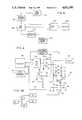
- FIG. 2is a functional block diagram illustrating the monitoring system in greater detail in accordance with one embodiment of the invention.
- FIG. 2Ais a simplified functional block diagram illustrating a modification of the monitoring system shown in FIG. 2.
- FIG. 3is a graphical illustration of an acoustical signal characteristic relied on for operation of the monitoring system.
- FIG. 4is a circuit diagram illustrating in greater detail the driver and resonance detector components of the system shown in FIG. 2.
- FIG. 4Ais a circuit diagram showing in greater detail the resonance verification section, diagramatically shown in FIG. 4, in accordance with one embodiment of the invention.
- FIG. 4Bis a block diagram showing a modification of the circuit arrangement of FIG. 4.
- FIG. 5is a graphical illustration of two of the signal characteristics associated with the acoustic receiver or sensor forming part of the system shown in FIG. 2.
- FIG. 6is a block diagram illustrating a method of obtaining and storing volume calculating data for the monitoring system.
- FIG. 1illustrates schematically a typical container in the form of a sealed tank 10 enclosing a fixed volume within which a fluent material is confined in the form of a body of liquid 12.
- the volume (V o ) of the liquid body 12may be varied by either inflow or outflow of liquid through conduit 14.
- a body of air or other gas 16fills the tank space above the body of liquid.
- the tankincludes an upwardly projecting neck portion 18 within which a throat passage 20 is formed.
- the foregoing tank configurationacts as a Helmholtz cavity resonator (as explained in Roberts U.S. Pat. No.
- the acoustical energy sourceis in the form of an acoustical transducer, or speaker 22 mounted on the upper end of neck portion 18.
- the excitation frequency of the acoustical energy output of speaker 22may be under control of a monitoring system 24 as shown in FIG. 1 to which an input is applied from an acoustical vibration sensor in the form of an acoustic receiver, transducer or microphone 26 mounted on the neck portion 18 adjacent its lower end.
- the output of speaker 22is varied in its excitation frequency within a frequency band encompassing resonance frequencies (f o ) that reflect the volume (V o ) of the liquid 12 being monitored by system 24 to provide a readout through any suitable display or meter 28.
- f oresonance frequencies
- the excitation frequency of the speaker output when cyclically swept through its frequency bandwill periodically produce resonance conditions, that are recognized by the monitoring system 24 through the sensor 26 to register the excitation frequencies of the speaker 22 corresponding thereto.
- the liquid volume (V o )is calculated from the registered frequency for readout through meter 28. By differentiating the liquid volume being calculated with respect to time, the system 24 may also provide a liquid flow rate readout.
- FIG. 2schematically outlines the monitoring system 24 in accordance with one embodiment of the invention in which operation of speaker source 22 is controlled by a cyclic frequency sweeps driver 32, establishing the excitation frequency band between a lower resonance frequency limit corresponding to an empty tank 10 and an upper resonance frequency limit corresponding to a full tank.
- the driver 32receives a time factor input from a low frequency signal generator 34 controlled by a system clock 36 through a signal converter 38.
- the signal converter 38also applies an output to a driver circuit 40 through which a resonance detector 42 is operated to recognize the establishment of resonance conditions within tank 10 from the output of sensor 26.
- the output of detector 42is applied to a data processing storage section 44 to which the output of signal generator 34 is also applied in order to register the excitation frequency at which resonance occurs to perform a liquid volume calculation and provide a readout to meter 28.
- the components 28, 36, 38 and 44may form part of, or their functions may be performed by, a data processor 46.
- excitation source 22 and sensor 26it should be understood that a wide variation of devices may be utilized depending on the frequency band of interest, cost, power requirements, environmental resistance, service life and other installational requirements.
- various loudspeaker devices of the electromagnetic, electrodynamic, piezo-electric, radiation, horn, air-modulated, mechanical or hydraulic activated, electric and electrostatic typesmay be utilized.
- crystal, piezo-electric, ribbon, carbon, ceramic, condenser, electret, moving coil and hot wire typescould be used to detect acoustical disturbances.
- a critical aspect of the present inventionresides in the recognition of resonance conditions from the sensing of acoustical disturbances by sensor 26 in response to excitation of the tank by the acoustical energy source 22.
- recognition of resonanceis achieved by detector 42 from measurement of at least one of the characteristics of the acoustical disturbances sensed by the sensor 26, as graphically depicted for example in FIG. 5.
- Curve 52 in FIG. 5is a typical plot of phase angle ( ⁇ ) as one measured signal characteristic of the acoustical disturbance sensed, versus excitation frequency (f). As shown in FIG.
- phase angle ( ⁇ )an abrupt change in the phase angle ( ⁇ ) occurs when the excitation frequency is of a cavity resonance value (f o ) denoted by the intersection of resonance line 54 with the frequency abscissa 56.
- detector 42is effective to recognize establishment of resonance and identify the frequency (f o ) at which such resonance occurs.
- the amplitude characteristic (A) of the acoustical disturbance sensed by sensor 26is plotted as curve 58.
- Such amplitude curve 58has a maximal peak or magnitude limit at 60 which occurs within a short interval during which resonance occurs to verify the recognition of resonance by the aforesaid detection of the abrupt change in the phase characteristic ( ⁇ ) in accordance with certain embodiments of the invention.
- the acoustical impedance characteristicscould be determined from the sensor output and its minimum limits detected to verify resonance, since acoustical impedance is at a minimum under resonance conditions.
- FIG. 4illustrates the detector 42 of a single sensor system in greater detail according to one embodiment, wherein the output of sensor 26 is fed through a signal coupling capacitor 64 and resistor 66 to an exclusive OR gate 68.
- the output of OR gate 68is fed to one input of OR gate 70, while its other input is coupled by OR gate 62 and series connected resistor 72 and capacitor 74 to the output of a voltage driven amplifier 76 of the driver circuit 40 having a feedback resistor 77.
- Amplifier 76receives its analog input from an 8-bit digital to analog type of signal converter 38 associated with the data processor 46 to which a feedback signal is fed from the detector 42 through line 78 from the output of its comparator 80.
- One input to comparator 80is coupled by resistor 82 to the output of the OR gate 70 while the other input is coupled by resistor 84 to a reference voltage source.
- the output of the voltage driven amplifier 76is fed to OR gate 62 through capacitor 74 and resistor 72 of the detector 42 and by resistor 90 to the input of the amplifier of an acoustic driver 88 having a feedback resistor 86 and an output coupled by resistor 87 to the sensor output.
- the driver amplifier 76is operative in response to its input from the data processor 46 through converter 38 to render comparator 80 operative simultaneously with the acoustical exciting speaker 22 under control of the data processor.
- OR gates 68, 70 and 62will supply an input to comparator 80 through resistor 82 that is a function of the phase angle ( ⁇ ) characterizing the acoustical input from the sensor 26, while the output of the comparator 80 in line 78 signals the phase change corresponding to resonance as depicted by curve 52 in FIG. 5.
- Such output in line 78is fed to the data processing storage component 44 associated with data processor 46 in order to register the resonance frequency (f o ) at which resonance detection occurs and to calculate the corresponding liquid volume (V o ) and/or flow rate.
- Verification of resonanceis achieved as aforementioned by limiting the detection of an abrupt change in phase angle through detector 42 to the approximate occurrence of maximum amplitude or minimum impedance through a verification section 96 interconnected between the sensor 26 and the signal converter 38 as shown in FIG. 4.
- FIG. 4Ashows one embodiment of the verification section 96 in detail based on measurement of signal amplitude.
- the output of sensor 26is applied to a capacitor 98 of section 96 maintained above a lower potential through resistor 100 to apply inputs in parallel through resistors 102 and 104 to amplifiers 106 and 106.
- the positive going output of amplifier 108is fed through diode 110 to the junction 112 from which an output voltage is applied through feedback resistor 114 to the input of amplifier 106 and through resistor 116 to the input of amplifier 108.
- the amplifier 108has a feedback resistor 118 so as to provide an output proportional to a peak amplitude signal applied to its input as a result of the circuit configuration described.
- the driver 88is coupled to a second sensor 26' rather than the sensor 26.
- the components shown in FIG. 4Botherwise form the same arrangement as shown in FIG. 4.
- FIG. 1illustrates one particular mounting arrangement for the speaker 22 and sensor 26, other mounting locations for the speaker and sensor are possible.
- FIG. 1Ashows the speaker 22 and sensor 26 mounted on an auxiliary cavity portion 120 of a modified tank configuration 10' in which the main portion of the tank enclosing the liquid body 12 is connected to the auxiliary cavity portion by a neck portion 18'.
- a membrane 122 within the neck portionseparates the auxiliary cavity portion from the body of air in the main portion of the tank to isolate it from spurious operational modes of vibration induced and thereby protects the sensor 26 against excessive vibrations.
- two series related Helmholtz resonatorsare established. The two resonators when so combined react one n the other forming a coupled system with two degrees of freedom. Resonance conditions are detected as hereinbefore described with respect to FIGS. 1-5. A marked increase in resonator sensitivity can be realized with the dual resonator system of this type when properly tuned.
- a data processor 46'functionally similar to data processor 46 may control operation of a dual mode type of transducer 48 through a cyclic switching mode control component 50 associated therewith.
- the transducer 48replaces both the separate speaker 22 and sensor 26 by alternately operating in a transmit mode to excite the resonator cavity of tank 10 and in a receive mode to sense the acoustical vibrations emitted from the tank in response to excitation and thereby enable detector 42' to recognize resonance conditions at excitation frequencies reflecting the liquid volume in tank 10.
- the fluent material hereinbefore referred to as liquid 12may also include viscous materials and particulate solids as well as mixtures thereof having a measurable flow type characteristic forming an interface with the air or other gaseous material filling the rest of the tank space. Static tanks as well as tanks mounted in moving vehicles may be monitored.
- the volume calculating data in the storage section 44 as hereinbefore described with respect to FIGS. 2 and 4,may be obtained and permanently stored therein by means of microprocessor memory chip as depicted in FIG. 6.
- tank 126 characteristic of a particular type of container installationsuch as the fuel tank of an automotive vehicle, is initially filled with the liquid to be monitored in order to establish an upper volume limit.
- the tank interioris then excited by acoustical energy from a source 128 corresponding to that of the monitoring system 24, with its frequency being varied by a frequency sweep control 130 until resonance is detected by detector 132.
- the output of detector 132 as well as frequency signals from frequency sweep control 130are fed to a data entry component 134 through which the memory 124 receives and stores the data relating to upper liquid volume limit for test tank 126 and the excitation frequency at which resonance occurs.
- the quantity of liquid in tank 126is then reduced in increments under control of signal output from control component 136.
- the tankis again excited by source 128 under control of frequency sweep control 130 until resonance is detected by detector 132.
- Datais thereby collected and stored in memory 124 to incrementally establish in the memory chip liquid volume as a function of resonance frequency between the upper volume limit and a lower volume limit corresponding to an empty tank.
- the memory chipmay then be plugged into the data processor to tailor the system to the desired installation. Data from installations other than automotive vehicles may be similarly obtained, including larger fuel tanks for marine vessels from which liquid fuel is incrementally withdrawn through an appropriate valve mechanism to program the microprocessor memory chip.
Landscapes
- Physics & Mathematics (AREA)
- Fluid Mechanics (AREA)
- General Physics & Mathematics (AREA)
- Acoustics & Sound (AREA)
- Electromagnetism (AREA)
- Thermal Sciences (AREA)
- Measurement Of Mechanical Vibrations Or Ultrasonic Waves (AREA)
Abstract
Description
Claims (18)
Priority Applications (1)
| Application Number | Priority Date | Filing Date | Title |
|---|---|---|---|
| US07/035,003US4811595A (en) | 1987-04-06 | 1987-04-06 | System for monitoring fluent material within a container |
Applications Claiming Priority (1)
| Application Number | Priority Date | Filing Date | Title |
|---|---|---|---|
| US07/035,003US4811595A (en) | 1987-04-06 | 1987-04-06 | System for monitoring fluent material within a container |
Publications (1)
| Publication Number | Publication Date |
|---|---|
| US4811595Atrue US4811595A (en) | 1989-03-14 |
Family
ID=21880034
Family Applications (1)
| Application Number | Title | Priority Date | Filing Date |
|---|---|---|---|
| US07/035,003Expired - Fee RelatedUS4811595A (en) | 1987-04-06 | 1987-04-06 | System for monitoring fluent material within a container |
Country Status (1)
| Country | Link |
|---|---|
| US (1) | US4811595A (en) |
Cited By (74)
| Publication number | Priority date | Publication date | Assignee | Title |
|---|---|---|---|---|
| US4949584A (en)* | 1989-05-08 | 1990-08-21 | Eaton Corporation | Apparatus for measuring depth of a fluid chamber |
| US4991433A (en)* | 1989-09-21 | 1991-02-12 | Applied Acoustic Research | Phase track system for monitoring fluid material within a container |
| US5027655A (en)* | 1988-10-05 | 1991-07-02 | Geotechnical Instruments (Uk) Limited | Method and apparatus for measuring liquid level in the ground |
| US5054316A (en)* | 1990-09-04 | 1991-10-08 | Keith Pratt | Volumetric measuring apparatus |
| US5060484A (en)* | 1990-06-12 | 1991-10-29 | Scotsman Group, Inc. | Bin level control circuit and transducer mounting system for an ice making machine |
| US5172595A (en)* | 1990-06-12 | 1992-12-22 | Scotsman Group, Inc. | Bin level control circuit and transducer mounting system for an ice making machine |
| US5184512A (en)* | 1989-01-16 | 1993-02-09 | Hrdlicka Armin W | Measuring the length of a column of fluid in a tube |
| US5251482A (en)* | 1990-07-16 | 1993-10-12 | Hughes Aircraft Company | Low frequency acoustic fuel sensor |
| US5261274A (en)* | 1990-05-25 | 1993-11-16 | Daniel M. Nemirow | Dynamic volumetric instrument gauge |
| US5349852A (en)* | 1986-03-04 | 1994-09-27 | Deka Products Limited Partnership | Pump controller using acoustic spectral analysis |
| US5385069A (en)* | 1992-08-06 | 1995-01-31 | Hydronautics Research, Inc. | Device for determining the volume of objects using a chamber with two resonators to compensate for temperature and humidity effects |
| DE4419301A1 (en)* | 1994-06-01 | 1995-12-07 | Krauss Maffei Ag | Helmholtz resonance |
| US5528933A (en)* | 1990-05-25 | 1996-06-25 | Nemirow; Daniel M. | Dynamic volumetric instrument gauge |
| US5560247A (en)* | 1992-09-16 | 1996-10-01 | Honda Giken Kogyo Kabushiki Kaisha | Exhaust gas sampling device for outboard motor |
| US5575310A (en)* | 1986-03-04 | 1996-11-19 | Deka Products Limited Partnership | Flow control system with volume-measuring system using a resonatable mass |
| US5644299A (en)* | 1993-07-29 | 1997-07-01 | Bindicator Company | Ultrasonic material level measurement |
| DE19646685A1 (en)* | 1996-11-12 | 1998-05-14 | Heuft Systemtechnik Gmbh | Methods for determining parameters, e.g. B. level, pressure, gas composition in closed containers |
| US5807092A (en)* | 1994-08-03 | 1998-09-15 | Tokai Corporation | Method of and device for detecting the residual of gas quantity in a cassette-type gas cylinder |
| RU2131590C1 (en)* | 1997-06-19 | 1999-06-10 | Тихоступ Михаил Тарасович | Method determining free space in vessel and device for its realization |
| DE19818768A1 (en)* | 1998-04-27 | 1999-10-28 | Heuft Systemtechnik Gmbh | Detecting liquid level in container especially closed can or tin |
| US20020012015A1 (en)* | 2000-05-18 | 2002-01-31 | Seiko Epson Corporation | Mounting structure, module, and liquid container |
| US20020015084A1 (en)* | 2000-06-15 | 2002-02-07 | Seiko Epson Corporation | Liquid charging method, liquid container, and method for manufacturing the same |
| US6397656B1 (en)* | 1999-01-25 | 2002-06-04 | Yamatake Corporation | System and method for detecting liquid serving as object to be detected in vessel using ultrasonic sensor |
| US20020105555A1 (en)* | 2000-05-18 | 2002-08-08 | Kenji Tsukada | Ink consumption detecting method, and ink jet recording apparatus |
| US20030043216A1 (en)* | 1999-05-20 | 2003-03-06 | Seiko Epson Corporation | Liquid container having liquid consumption detecting device |
| US6582379B1 (en) | 1998-09-25 | 2003-06-24 | Maersk Medical A/S | Apparatus and method of measuring the flow of a liquid, in particular urine, from a patient |
| US6696962B2 (en)* | 2001-05-14 | 2004-02-24 | John M. Kelly | Resonant tube level sensor |
| US20040079149A1 (en)* | 2002-09-06 | 2004-04-29 | Ulf Sawert | Fuel level indication assembly |
| US6729184B2 (en) | 2000-07-28 | 2004-05-04 | Seiko Epson Corporation | Detector of liquid consumption condition |
| US6793305B2 (en) | 2000-05-18 | 2004-09-21 | Seiko Epson Corporation | Method and apparatus for detecting consumption of ink |
| US6828912B2 (en)* | 2001-05-14 | 2004-12-07 | John Michael Kelly | Resonant tube sensor |
| US20050066962A1 (en)* | 2003-09-25 | 2005-03-31 | Deka Products Limited Partnership | Metering system and method for aerosol delivery |
| US20050068528A1 (en)* | 2003-09-25 | 2005-03-31 | Deka Products Limited Partnership | Detection system and method for aerosol delivery |
| US20050193818A1 (en)* | 2004-02-03 | 2005-09-08 | University Of Denver | Method and Apparatus for Acoustic Sensing of Structures |
| US20060000276A1 (en)* | 2004-07-02 | 2006-01-05 | Bran Ferren | Method of measuring amount of substances |
| US20060023009A1 (en)* | 2000-07-07 | 2006-02-02 | Seiko Epson Corporation | Liquid container, ink jet recording apparatus, apparatus and method for controlling the same, apparatus and method for detecting liquid consumption state |
| US7118227B2 (en) | 2001-04-25 | 2006-10-10 | Matsushita Electric Industrial Co., Ltd. | Projection display device |
| US20060274128A1 (en)* | 2000-05-18 | 2006-12-07 | Seiko Epson Corporation | Ink consumption detecting method, and ink jet recording apparatus |
| DE102004017560B4 (en)* | 2003-04-10 | 2007-03-15 | Vega Grieshaber Kg | Level gauge for bottles |
| US20070072534A1 (en)* | 2005-09-26 | 2007-03-29 | Coin Acceptors, Inc. | Tube status sensing method and control field of the invention |
| US20070193350A1 (en)* | 2004-03-24 | 2007-08-23 | Kyoto University | Volume measuring device and method |
| DE102006009556A1 (en)* | 2006-02-28 | 2007-09-06 | Siemens Ag | Method for analyzing the electrolyte system of a battery and associated device |
| US20070219496A1 (en)* | 2006-02-09 | 2007-09-20 | Dean Kamen | Pumping fluid delivery systems and methods using force application assembly |
| US20090151460A1 (en)* | 2007-12-14 | 2009-06-18 | Thorne Iv Edward H | Filter and spe plate clogged well detection |
| US20090281497A1 (en)* | 2007-12-31 | 2009-11-12 | Dean Kamen | Wearable pump assembly |
| GB2478522A (en)* | 2010-03-04 | 2011-09-14 | Nicholas Peter Haddock | Aircraft pitot blockage / static warning system |
| US8496646B2 (en) | 2007-02-09 | 2013-07-30 | Deka Products Limited Partnership | Infusion pump assembly |
| US20140298902A1 (en)* | 2013-04-08 | 2014-10-09 | Wes Clayton Fannin | System and Method for Environmental Measurements |
| US9057638B2 (en)* | 2012-11-09 | 2015-06-16 | Robert H. Cameron | System and method for determining the level of a substance in a container based on measurement of resonance from an acoustic circuit that includes unfilled space within the container that changes size as substance is added or removed from the container |
| US9322697B2 (en) | 2012-11-09 | 2016-04-26 | Robert H. Cameron | System and method for determining the level of a substance in a container based on measurement of resonance from an acoustic circuit that includes unfilled space within the container that changes size as substance is added or removed from the container |
| EP3112896A1 (en)* | 2012-07-11 | 2017-01-04 | Sanofi-Aventis Deutschland GmbH | Arrangement and method for determining a stopper position |
| US20170332813A1 (en)* | 2016-05-19 | 2017-11-23 | Baltek Co., Limited | Bottle having water volume measuring function |
| US10184821B2 (en) | 2012-11-09 | 2019-01-22 | Robert H. Cameron | System and method for determining the level of a substance in a container based on measurement of resonance from an acoustic circuit that includes unfilled space within the container that changes size as substance is added or removed from the container |
| US20200348162A1 (en)* | 2017-11-15 | 2020-11-05 | Piaggio & C. Spa | A method and system for estimating the volume of fuel contained in a tank of a transport vehicle |
| US11364335B2 (en) | 2006-02-09 | 2022-06-21 | Deka Products Limited Partnership | Apparatus, system and method for fluid delivery |
| US11395877B2 (en) | 2006-02-09 | 2022-07-26 | Deka Products Limited Partnership | Systems and methods for fluid delivery |
| US11404776B2 (en) | 2007-12-31 | 2022-08-02 | Deka Products Limited Partnership | Split ring resonator antenna adapted for use in wirelessly controlled medical device |
| US11426512B2 (en) | 2006-02-09 | 2022-08-30 | Deka Products Limited Partnership | Apparatus, systems and methods for an infusion pump assembly |
| US11478623B2 (en) | 2006-02-09 | 2022-10-25 | Deka Products Limited Partnership | Infusion pump assembly |
| US11497686B2 (en) | 2007-12-31 | 2022-11-15 | Deka Products Limited Partnership | Apparatus, system and method for fluid delivery |
| US11497846B2 (en) | 2006-02-09 | 2022-11-15 | Deka Products Limited Partnership | Patch-sized fluid delivery systems and methods |
| US11524151B2 (en) | 2012-03-07 | 2022-12-13 | Deka Products Limited Partnership | Apparatus, system and method for fluid delivery |
| US11523972B2 (en) | 2018-04-24 | 2022-12-13 | Deka Products Limited Partnership | Apparatus, system and method for fluid delivery |
| US11534542B2 (en) | 2007-12-31 | 2022-12-27 | Deka Products Limited Partnership | Apparatus, system and method for fluid delivery |
| US11597541B2 (en) | 2013-07-03 | 2023-03-07 | Deka Products Limited Partnership | Apparatus, system and method for fluid delivery |
| US11642283B2 (en) | 2007-12-31 | 2023-05-09 | Deka Products Limited Partnership | Method for fluid delivery |
| US11723841B2 (en) | 2007-12-31 | 2023-08-15 | Deka Products Limited Partnership | Apparatus, system and method for fluid delivery |
| US11890448B2 (en) | 2006-02-09 | 2024-02-06 | Deka Products Limited Partnership | Method and system for shape-memory alloy wire control |
| US11964126B2 (en) | 2006-02-09 | 2024-04-23 | Deka Products Limited Partnership | Infusion pump assembly |
| US12064590B2 (en) | 2006-02-09 | 2024-08-20 | Deka Products Limited Partnership | Patch-sized fluid delivery systems and methods |
| US12070574B2 (en) | 2006-02-09 | 2024-08-27 | Deka Products Limited Partnership | Apparatus, systems and methods for an infusion pump assembly |
| US12151080B2 (en) | 2006-02-09 | 2024-11-26 | Deka Products Limited Partnership | Adhesive and peripheral systems and methods for medical devices |
| US20240401997A1 (en)* | 2023-06-05 | 2024-12-05 | Tendo Technologies Inc. | Device, system, and method for fluid mass determination |
| US12274857B2 (en) | 2006-02-09 | 2025-04-15 | Deka Products Limited Partnership | Method and system for shape-memory alloy wire control |
Citations (32)
| Publication number | Priority date | Publication date | Assignee | Title |
|---|---|---|---|---|
| US2666326A (en)* | 1947-12-22 | 1954-01-19 | Poole | Volumetric measuring apparatus |
| US2706906A (en)* | 1949-06-01 | 1955-04-26 | Magnetic Amplifier Corp | Modulus determining system |
| US2753542A (en)* | 1953-09-03 | 1956-07-03 | Bogue Elec Mfg Co | Calibrated apparatus for measuring liquid levels |
| US2998723A (en)* | 1956-06-15 | 1961-09-05 | Acoustica Associates Inc | Sonic wave conductor |
| US3075382A (en)* | 1958-09-09 | 1963-01-29 | Owens Illinois Glass Co | Apparatus for acoustically measuring volume |
| US3100390A (en)* | 1957-12-26 | 1963-08-13 | Automation Prod | Method of and apparatus for determining physical properties of materials |
| US3110890A (en)* | 1958-03-03 | 1963-11-12 | Vernon C Westcott | Apparatus for measuring fluid level |
| US3163843A (en)* | 1961-10-02 | 1964-12-29 | North American Aviation Inc | Liquid level indicator |
| US3220258A (en)* | 1956-05-18 | 1965-11-30 | Acoustica Associates Inc | Sensing the presence or absence of material |
| US3286098A (en)* | 1963-02-28 | 1966-11-15 | Mobil Oil Corp | Methods and apparatus for determining factors related to sonic velocity in a gas |
| US3324716A (en)* | 1963-12-12 | 1967-06-13 | United States Steel Corp | Method and apparatus for acoustically determining the size of cast ingots |
| US3523186A (en)* | 1967-10-18 | 1970-08-04 | Simmonds Precision Products | Attitude error correction fluid gauging system employing radiation detectors and error storage techniques |
| US3540275A (en)* | 1968-02-28 | 1970-11-17 | Bendix Corp | Method and apparatus for measuring liquid volume in a tank |
| US3596510A (en)* | 1970-02-04 | 1971-08-03 | Nasa | Resonant infrasonic gauging apparatus |
| US3603149A (en)* | 1969-09-03 | 1971-09-07 | Us Army | Ultrasonic liquid level indicator |
| US3745829A (en)* | 1971-10-18 | 1973-07-17 | Electronique Appliquee | Level measuring equipments |
| SU460445A1 (en)* | 1970-06-03 | 1975-02-15 | Научно-Исследовательский Сектор Всесоюзного Ордена Ленина Проектно-Изыскательского И Научно-Исследовательского Института "Гидропроект" Им.С.Я.Жука | The method of determining the content of material in the tank |
| US3985030A (en)* | 1974-10-29 | 1976-10-12 | William Mcgeoch & Company | Ultrasonic acoustic pulse echo ranging system |
| US4063457A (en)* | 1976-09-27 | 1977-12-20 | Envirotech Corporation | Ultrasonic level sensing device |
| US4072046A (en)* | 1976-09-03 | 1978-02-07 | The Dow Chemical Company | Acoustic pycnometer |
| SU601577A1 (en)* | 1976-12-06 | 1978-04-05 | Ивано-Франковский Институт Нефти И Газа | Acoustic level meter |
| US4114441A (en)* | 1976-06-09 | 1978-09-19 | G. H. Endress & Co. | Method and apparatus for measuring the height of filling material on a surface, such as within a container |
| US4130018A (en)* | 1977-08-30 | 1978-12-19 | Envirotech Corporation | Ultrasonic transducer with reference reflector |
| US4147050A (en)* | 1976-03-25 | 1979-04-03 | Gull Airborne Instruments, Inc. | Apparatus for testing a capacitance responsive gaging system |
| US4535628A (en)* | 1981-05-22 | 1985-08-20 | Hope Bjoern R | Apparatus for level measurements |
| US4535627A (en)* | 1982-04-01 | 1985-08-20 | Battelle Memorial Institute | Method of and apparatus for determining the level of liquid in a vessel |
| US4561298A (en)* | 1983-06-30 | 1985-12-31 | Pond John B | Volume measurement system |
| US4599892A (en)* | 1984-12-04 | 1986-07-15 | Doshi Navin H | Volume measuring apparatus |
| US4640130A (en)* | 1984-10-29 | 1987-02-03 | Baylor College Of Medicine | Method and apparatus for acoustically measuring the volume of an object |
| US4689553A (en)* | 1985-04-12 | 1987-08-25 | Jodon Engineering Associates, Inc. | Method and system for monitoring position of a fluid actuator employing microwave resonant cavity principles |
| US4704902A (en)* | 1984-12-04 | 1987-11-10 | Doshi Navin H | Acoustical volume/pressure measurement device |
| US4713966A (en)* | 1984-12-21 | 1987-12-22 | Enpece Ab | Method and apparatus for volume measurement |
- 1987
- 1987-04-06USUS07/035,003patent/US4811595A/ennot_activeExpired - Fee Related
Patent Citations (32)
| Publication number | Priority date | Publication date | Assignee | Title |
|---|---|---|---|---|
| US2666326A (en)* | 1947-12-22 | 1954-01-19 | Poole | Volumetric measuring apparatus |
| US2706906A (en)* | 1949-06-01 | 1955-04-26 | Magnetic Amplifier Corp | Modulus determining system |
| US2753542A (en)* | 1953-09-03 | 1956-07-03 | Bogue Elec Mfg Co | Calibrated apparatus for measuring liquid levels |
| US3220258A (en)* | 1956-05-18 | 1965-11-30 | Acoustica Associates Inc | Sensing the presence or absence of material |
| US2998723A (en)* | 1956-06-15 | 1961-09-05 | Acoustica Associates Inc | Sonic wave conductor |
| US3100390A (en)* | 1957-12-26 | 1963-08-13 | Automation Prod | Method of and apparatus for determining physical properties of materials |
| US3110890A (en)* | 1958-03-03 | 1963-11-12 | Vernon C Westcott | Apparatus for measuring fluid level |
| US3075382A (en)* | 1958-09-09 | 1963-01-29 | Owens Illinois Glass Co | Apparatus for acoustically measuring volume |
| US3163843A (en)* | 1961-10-02 | 1964-12-29 | North American Aviation Inc | Liquid level indicator |
| US3286098A (en)* | 1963-02-28 | 1966-11-15 | Mobil Oil Corp | Methods and apparatus for determining factors related to sonic velocity in a gas |
| US3324716A (en)* | 1963-12-12 | 1967-06-13 | United States Steel Corp | Method and apparatus for acoustically determining the size of cast ingots |
| US3523186A (en)* | 1967-10-18 | 1970-08-04 | Simmonds Precision Products | Attitude error correction fluid gauging system employing radiation detectors and error storage techniques |
| US3540275A (en)* | 1968-02-28 | 1970-11-17 | Bendix Corp | Method and apparatus for measuring liquid volume in a tank |
| US3603149A (en)* | 1969-09-03 | 1971-09-07 | Us Army | Ultrasonic liquid level indicator |
| US3596510A (en)* | 1970-02-04 | 1971-08-03 | Nasa | Resonant infrasonic gauging apparatus |
| SU460445A1 (en)* | 1970-06-03 | 1975-02-15 | Научно-Исследовательский Сектор Всесоюзного Ордена Ленина Проектно-Изыскательского И Научно-Исследовательского Института "Гидропроект" Им.С.Я.Жука | The method of determining the content of material in the tank |
| US3745829A (en)* | 1971-10-18 | 1973-07-17 | Electronique Appliquee | Level measuring equipments |
| US3985030A (en)* | 1974-10-29 | 1976-10-12 | William Mcgeoch & Company | Ultrasonic acoustic pulse echo ranging system |
| US4147050A (en)* | 1976-03-25 | 1979-04-03 | Gull Airborne Instruments, Inc. | Apparatus for testing a capacitance responsive gaging system |
| US4114441A (en)* | 1976-06-09 | 1978-09-19 | G. H. Endress & Co. | Method and apparatus for measuring the height of filling material on a surface, such as within a container |
| US4072046A (en)* | 1976-09-03 | 1978-02-07 | The Dow Chemical Company | Acoustic pycnometer |
| US4063457A (en)* | 1976-09-27 | 1977-12-20 | Envirotech Corporation | Ultrasonic level sensing device |
| SU601577A1 (en)* | 1976-12-06 | 1978-04-05 | Ивано-Франковский Институт Нефти И Газа | Acoustic level meter |
| US4130018A (en)* | 1977-08-30 | 1978-12-19 | Envirotech Corporation | Ultrasonic transducer with reference reflector |
| US4535628A (en)* | 1981-05-22 | 1985-08-20 | Hope Bjoern R | Apparatus for level measurements |
| US4535627A (en)* | 1982-04-01 | 1985-08-20 | Battelle Memorial Institute | Method of and apparatus for determining the level of liquid in a vessel |
| US4561298A (en)* | 1983-06-30 | 1985-12-31 | Pond John B | Volume measurement system |
| US4640130A (en)* | 1984-10-29 | 1987-02-03 | Baylor College Of Medicine | Method and apparatus for acoustically measuring the volume of an object |
| US4599892A (en)* | 1984-12-04 | 1986-07-15 | Doshi Navin H | Volume measuring apparatus |
| US4704902A (en)* | 1984-12-04 | 1987-11-10 | Doshi Navin H | Acoustical volume/pressure measurement device |
| US4713966A (en)* | 1984-12-21 | 1987-12-22 | Enpece Ab | Method and apparatus for volume measurement |
| US4689553A (en)* | 1985-04-12 | 1987-08-25 | Jodon Engineering Associates, Inc. | Method and system for monitoring position of a fluid actuator employing microwave resonant cavity principles |
Cited By (173)
| Publication number | Priority date | Publication date | Assignee | Title |
|---|---|---|---|---|
| US5349852A (en)* | 1986-03-04 | 1994-09-27 | Deka Products Limited Partnership | Pump controller using acoustic spectral analysis |
| US5575310A (en)* | 1986-03-04 | 1996-11-19 | Deka Products Limited Partnership | Flow control system with volume-measuring system using a resonatable mass |
| US5533389A (en)* | 1986-03-04 | 1996-07-09 | Deka Products Limited Partnership | Method and system for measuring volume and controlling flow |
| US5526844A (en)* | 1986-03-04 | 1996-06-18 | Deka Products Limited Partnership | Flow conrol system |
| US5027655A (en)* | 1988-10-05 | 1991-07-02 | Geotechnical Instruments (Uk) Limited | Method and apparatus for measuring liquid level in the ground |
| US5184512A (en)* | 1989-01-16 | 1993-02-09 | Hrdlicka Armin W | Measuring the length of a column of fluid in a tube |
| US4949584A (en)* | 1989-05-08 | 1990-08-21 | Eaton Corporation | Apparatus for measuring depth of a fluid chamber |
| US4991433A (en)* | 1989-09-21 | 1991-02-12 | Applied Acoustic Research | Phase track system for monitoring fluid material within a container |
| US5261274A (en)* | 1990-05-25 | 1993-11-16 | Daniel M. Nemirow | Dynamic volumetric instrument gauge |
| US5528933A (en)* | 1990-05-25 | 1996-06-25 | Nemirow; Daniel M. | Dynamic volumetric instrument gauge |
| US5172595A (en)* | 1990-06-12 | 1992-12-22 | Scotsman Group, Inc. | Bin level control circuit and transducer mounting system for an ice making machine |
| US5060484A (en)* | 1990-06-12 | 1991-10-29 | Scotsman Group, Inc. | Bin level control circuit and transducer mounting system for an ice making machine |
| US5251482A (en)* | 1990-07-16 | 1993-10-12 | Hughes Aircraft Company | Low frequency acoustic fuel sensor |
| US5054316A (en)* | 1990-09-04 | 1991-10-08 | Keith Pratt | Volumetric measuring apparatus |
| US5385069A (en)* | 1992-08-06 | 1995-01-31 | Hydronautics Research, Inc. | Device for determining the volume of objects using a chamber with two resonators to compensate for temperature and humidity effects |
| US5560247A (en)* | 1992-09-16 | 1996-10-01 | Honda Giken Kogyo Kabushiki Kaisha | Exhaust gas sampling device for outboard motor |
| US5644299A (en)* | 1993-07-29 | 1997-07-01 | Bindicator Company | Ultrasonic material level measurement |
| DE4419301A1 (en)* | 1994-06-01 | 1995-12-07 | Krauss Maffei Ag | Helmholtz resonance |
| US5807092A (en)* | 1994-08-03 | 1998-09-15 | Tokai Corporation | Method of and device for detecting the residual of gas quantity in a cassette-type gas cylinder |
| DE19646685A1 (en)* | 1996-11-12 | 1998-05-14 | Heuft Systemtechnik Gmbh | Methods for determining parameters, e.g. B. level, pressure, gas composition in closed containers |
| US6338272B1 (en) | 1996-11-12 | 2002-01-15 | Heuft Systemtechnik Gmbh | Method for determining parameters, for example level, pressure, gas composition in closed containers |
| RU2131590C1 (en)* | 1997-06-19 | 1999-06-10 | Тихоступ Михаил Тарасович | Method determining free space in vessel and device for its realization |
| DE19818768A1 (en)* | 1998-04-27 | 1999-10-28 | Heuft Systemtechnik Gmbh | Detecting liquid level in container especially closed can or tin |
| US6443004B1 (en) | 1998-04-27 | 2002-09-03 | Heuft Systemtechnik Gmbh | Method and device for determining the filling level in containers |
| US6582379B1 (en) | 1998-09-25 | 2003-06-24 | Maersk Medical A/S | Apparatus and method of measuring the flow of a liquid, in particular urine, from a patient |
| US6397656B1 (en)* | 1999-01-25 | 2002-06-04 | Yamatake Corporation | System and method for detecting liquid serving as object to be detected in vessel using ultrasonic sensor |
| US7383727B2 (en)* | 1999-05-20 | 2008-06-10 | Seiko Epson Corporation | Liquid cotainer having a liquid consumption detecting device therein |
| US20060272404A1 (en)* | 1999-05-20 | 2006-12-07 | Seiko Epson Corporation | Liquid consumption status detecting method, liquid container, and ink cartridge |
| US20030043216A1 (en)* | 1999-05-20 | 2003-03-06 | Seiko Epson Corporation | Liquid container having liquid consumption detecting device |
| US20070277603A1 (en)* | 1999-05-20 | 2007-12-06 | Seiko Epson Corporation | Liquid consumption status detecting method, liquid container, and ink cartridge |
| US20030117451A1 (en)* | 1999-05-20 | 2003-06-26 | Seiko Epson Corporation | Liquid container having liquid consumption detecting device |
| US20030117450A1 (en)* | 1999-05-20 | 2003-06-26 | Seiko Epson Corporation | Liquid container having liquid consumption detecing device |
| US20030140694A1 (en)* | 1999-05-20 | 2003-07-31 | Minoru Usui | Liquid container having a liquid consumption detecting device therein |
| US7251996B2 (en) | 1999-05-20 | 2007-08-07 | Seiko Epson Corporation | Liquid detecting piezoelectric device, liquid container and mounting module member |
| US20040056910A1 (en)* | 1999-05-20 | 2004-03-25 | Seiko Epson Corporation | Liquid consumption status detecting method, liquid container, and ink cartridge |
| US20090021566A1 (en)* | 1999-05-20 | 2009-01-22 | Seiko Epson Corporation | Liquid Consumption Status Detecting Method, Liquid Container, and Ink Cartridge |
| US7175244B2 (en) | 1999-05-20 | 2007-02-13 | Seiko Epson Corporation | Liquid container having liquid consumption detecting device |
| US6745626B2 (en) | 1999-05-20 | 2004-06-08 | Seiko Epson Corporation | Liquid detecting piezoelectric device, liquid container and mounting module member |
| US7188520B2 (en) | 1999-05-20 | 2007-03-13 | Seiko Epson Corporation | Liquid consumption status detecting method, liquid container, and ink cartridge |
| US7325450B2 (en)* | 1999-05-20 | 2008-02-05 | Seiko Epson Corporation | Liquid consumption status detecting method, liquid container, and ink cartridge |
| US6799820B1 (en) | 1999-05-20 | 2004-10-05 | Seiko Epson Corporation | Liquid container having a liquid detecting device |
| US20040226361A1 (en)* | 1999-05-20 | 2004-11-18 | Seiko Epson Corporation | Liquid detecting piezoelectric device, liquid container and mounting module member |
| US7267000B1 (en)* | 1999-05-20 | 2007-09-11 | Seiko Epson Corporation | Liquid consumption status detecting method, liquid container, and ink cartridge |
| US20060001714A1 (en)* | 1999-05-20 | 2006-01-05 | Seiko Epson Corporation | Liquid container having liquid consumption detecting device |
| US7281776B2 (en) | 1999-05-20 | 2007-10-16 | Seiko Epson Corporation | Liquid container having liquid consumption detecing device |
| US7434462B2 (en) | 1999-05-20 | 2008-10-14 | Seiko Epson Corporation | Liquid consumption status detecting method, liquid container, and ink cartridge |
| US7225670B2 (en) | 2000-05-18 | 2007-06-05 | Seiko Epson Corporation | Mounting structure, module, and liquid container |
| US20020105555A1 (en)* | 2000-05-18 | 2002-08-08 | Kenji Tsukada | Ink consumption detecting method, and ink jet recording apparatus |
| US7878609B2 (en) | 2000-05-18 | 2011-02-01 | Seiko Epson Corporation | Mounting structure, module, and liquid container |
| US7971945B2 (en) | 2000-05-18 | 2011-07-05 | Seiko Epson Corporation | Ink consumption detecting method, and ink jet recording apparatus |
| US20020012015A1 (en)* | 2000-05-18 | 2002-01-31 | Seiko Epson Corporation | Mounting structure, module, and liquid container |
| US20070085865A1 (en)* | 2000-05-18 | 2007-04-19 | Seiko Epson Corporation | Mounting structure, module, and liquid container |
| US20060274128A1 (en)* | 2000-05-18 | 2006-12-07 | Seiko Epson Corporation | Ink consumption detecting method, and ink jet recording apparatus |
| US7137679B2 (en) | 2000-05-18 | 2006-11-21 | Seiko Epson Corporation | Ink consumption detecting method, and ink jet recording apparatus |
| US6793305B2 (en) | 2000-05-18 | 2004-09-21 | Seiko Epson Corporation | Method and apparatus for detecting consumption of ink |
| US7798620B2 (en) | 2000-06-15 | 2010-09-21 | Seiko Epson Corporation | Method of manufacturing a liquid container |
| US20070103493A1 (en)* | 2000-06-15 | 2007-05-10 | Seiko Epson Corporation | Liquid charging method, liquid container, and method for manufacturing the same |
| US7156506B2 (en) | 2000-06-15 | 2007-01-02 | Seiko Epson Corporation | Liquid charging method, liquid container, and method for manufacturing the same |
| US20020015084A1 (en)* | 2000-06-15 | 2002-02-07 | Seiko Epson Corporation | Liquid charging method, liquid container, and method for manufacturing the same |
| US7306308B2 (en) | 2000-07-07 | 2007-12-11 | Seiko Epson Corporation | Liquid container, ink jet recording apparatus, apparatus and method for controlling the same, apparatus and method for detecting liquid consumption state |
| US7008034B2 (en) | 2000-07-07 | 2006-03-07 | Seiko Epson Corporation | Liquid container, ink-jet recording apparatus, device and method for controlling the apparatus, liquid consumption sensing device and method |
| US20060023009A1 (en)* | 2000-07-07 | 2006-02-02 | Seiko Epson Corporation | Liquid container, ink jet recording apparatus, apparatus and method for controlling the same, apparatus and method for detecting liquid consumption state |
| US20040168514A1 (en)* | 2000-07-28 | 2004-09-02 | Seiko Epson Corporation | Detector of liquid consumption condition |
| US7086281B2 (en) | 2000-07-28 | 2006-08-08 | Seiko Epson Corporation | Detector of liquid consumption condition |
| US6729184B2 (en) | 2000-07-28 | 2004-05-04 | Seiko Epson Corporation | Detector of liquid consumption condition |
| US7118227B2 (en) | 2001-04-25 | 2006-10-10 | Matsushita Electric Industrial Co., Ltd. | Projection display device |
| US6828912B2 (en)* | 2001-05-14 | 2004-12-07 | John Michael Kelly | Resonant tube sensor |
| US6696962B2 (en)* | 2001-05-14 | 2004-02-24 | John M. Kelly | Resonant tube level sensor |
| US6951131B2 (en)* | 2002-09-06 | 2005-10-04 | Delphi Technologies, Inc. | Fuel level indication assembly |
| US20040079149A1 (en)* | 2002-09-06 | 2004-04-29 | Ulf Sawert | Fuel level indication assembly |
| DE102004017560B4 (en)* | 2003-04-10 | 2007-03-15 | Vega Grieshaber Kg | Level gauge for bottles |
| US20050066962A1 (en)* | 2003-09-25 | 2005-03-31 | Deka Products Limited Partnership | Metering system and method for aerosol delivery |
| US9610414B2 (en) | 2003-09-25 | 2017-04-04 | Deka Products Limited Partnership | Device to meter fluid |
| US10245395B2 (en)* | 2003-09-25 | 2019-04-02 | Deka Products Limited Partnership | Metering system and method for aerosol delivery |
| US9550033B2 (en) | 2003-09-25 | 2017-01-24 | Deka Products Limited Partnership | Metering system and method for fluid delivery |
| US9550035B2 (en) | 2003-09-25 | 2017-01-24 | Deka Products Limited Partnership | Method to deliver medication |
| US9550034B2 (en) | 2003-09-25 | 2017-01-24 | Deka Products Limited Partnership | Metering system and method for aerosol delivery |
| US20140196534A1 (en)* | 2003-09-25 | 2014-07-17 | Deka Products Limited Partnership | Metering System and Method for Aerosol Delivery |
| WO2005030306A3 (en)* | 2003-09-25 | 2007-10-18 | Deka Products Lp | Metering system and methods for aerosol delivery |
| US8687191B2 (en) | 2003-09-25 | 2014-04-01 | Deka Products Limited Partnership | Detection system and method for aerosol delivery |
| US7146977B2 (en) | 2003-09-25 | 2006-12-12 | Deka Products Limited Partnership | Valve system and method for aerosol delivery |
| US7066029B2 (en) | 2003-09-25 | 2006-06-27 | Deka Products Limited Partnership | System and method for improved volume measurement |
| US7305984B2 (en) | 2003-09-25 | 2007-12-11 | Deka Products Limited Partnership | Metering system and method for aerosol delivery |
| US7021560B2 (en) | 2003-09-25 | 2006-04-04 | Deka Products Limited Partnership | System and method for aerosol delivery |
| US8511299B2 (en) | 2003-09-25 | 2013-08-20 | Deka Products Limited Partnership | Metering system and method for aerosol delivery |
| US7342660B2 (en) | 2003-09-25 | 2008-03-11 | Deka Products Limited Partnership | Detection system and method for aerosol delivery |
| US20050066963A1 (en)* | 2003-09-25 | 2005-03-31 | Deka Products Limited Partnership | Valve system and method for aerosol delivery |
| EP2269743A3 (en)* | 2003-09-25 | 2011-04-27 | Deka Products Limited Partnership | Metering system and methods for aerosol delivery |
| US20050066735A1 (en)* | 2003-09-25 | 2005-03-31 | Deka Products Limited Partnership | System and method for improved volume measurement |
| US20110079220A1 (en)* | 2003-09-25 | 2011-04-07 | Deka Products Limited Partnership | Detection System and Method for Aerosol Delivery |
| US20090213373A1 (en)* | 2003-09-25 | 2009-08-27 | Deka Products Limited Partnership | Detection System and Method for Aerosol Delivery |
| US20110029260A1 (en)* | 2003-09-25 | 2011-02-03 | Deka Products Limited Partnership | Metering system and method for aerosol delivery |
| US20050067511A1 (en)* | 2003-09-25 | 2005-03-31 | Deka Products Limited Partnership | System and method for aerosol delivery |
| US20050068528A1 (en)* | 2003-09-25 | 2005-03-31 | Deka Products Limited Partnership | Detection system and method for aerosol delivery |
| US20050193818A1 (en)* | 2004-02-03 | 2005-09-08 | University Of Denver | Method and Apparatus for Acoustic Sensing of Structures |
| US7296472B2 (en)* | 2004-02-03 | 2007-11-20 | University Of Denver | Method and apparatus for acoustic sensing of structures |
| JPWO2005090932A1 (en)* | 2004-03-24 | 2008-02-07 | 国立大学法人京都大学 | Volume measuring apparatus and method |
| US7707877B2 (en)* | 2004-03-24 | 2010-05-04 | Kyoto University | Volume measuring device and method |
| US20070193350A1 (en)* | 2004-03-24 | 2007-08-23 | Kyoto University | Volume measuring device and method |
| US20060000276A1 (en)* | 2004-07-02 | 2006-01-05 | Bran Ferren | Method of measuring amount of substances |
| US20070072534A1 (en)* | 2005-09-26 | 2007-03-29 | Coin Acceptors, Inc. | Tube status sensing method and control field of the invention |
| US11364335B2 (en) | 2006-02-09 | 2022-06-21 | Deka Products Limited Partnership | Apparatus, system and method for fluid delivery |
| US11426512B2 (en) | 2006-02-09 | 2022-08-30 | Deka Products Limited Partnership | Apparatus, systems and methods for an infusion pump assembly |
| US8414522B2 (en) | 2006-02-09 | 2013-04-09 | Deka Products Limited Partnership | Fluid delivery systems and methods |
| US12311143B2 (en) | 2006-02-09 | 2025-05-27 | Deka Products Limited Partnership | Adhesive and peripheral systems and methods for medical devices |
| US12274857B2 (en) | 2006-02-09 | 2025-04-15 | Deka Products Limited Partnership | Method and system for shape-memory alloy wire control |
| US12151080B2 (en) | 2006-02-09 | 2024-11-26 | Deka Products Limited Partnership | Adhesive and peripheral systems and methods for medical devices |
| US8545445B2 (en) | 2006-02-09 | 2013-10-01 | Deka Products Limited Partnership | Patch-sized fluid delivery systems and methods |
| US12070574B2 (en) | 2006-02-09 | 2024-08-27 | Deka Products Limited Partnership | Apparatus, systems and methods for an infusion pump assembly |
| US12064590B2 (en) | 2006-02-09 | 2024-08-20 | Deka Products Limited Partnership | Patch-sized fluid delivery systems and methods |
| US12036387B2 (en) | 2006-02-09 | 2024-07-16 | Deka Products Limited Partnership | Device to determine volume of fluid dispensed |
| US11992650B2 (en) | 2006-02-09 | 2024-05-28 | Deka Products Limited Partnership | Adhesive and peripheral systems and methods for medical devices |
| US11964126B2 (en) | 2006-02-09 | 2024-04-23 | Deka Products Limited Partnership | Infusion pump assembly |
| US11904134B2 (en) | 2006-02-09 | 2024-02-20 | Deka Products Limited Partnership | Patch-sized fluid delivery systems and methods |
| US8998850B2 (en) | 2006-02-09 | 2015-04-07 | Deka Products Limited Partnership | Adhesive and peripheral systems and methods for medical devices |
| US11890448B2 (en) | 2006-02-09 | 2024-02-06 | Deka Products Limited Partnership | Method and system for shape-memory alloy wire control |
| US11786651B2 (en) | 2006-02-09 | 2023-10-17 | Deka Products Limited Partnership | Patch-sized fluid delivery system |
| US11738139B2 (en) | 2006-02-09 | 2023-08-29 | Deka Products Limited Partnership | Patch-sized fluid delivery systems and methods |
| US11690952B2 (en) | 2006-02-09 | 2023-07-04 | Deka Products Limited Partnership | Pumping fluid delivery systems and methods using force application assembly |
| US20070228071A1 (en)* | 2006-02-09 | 2007-10-04 | Dean Kamen | Fluid delivery systems and methods |
| US20070219496A1 (en)* | 2006-02-09 | 2007-09-20 | Dean Kamen | Pumping fluid delivery systems and methods using force application assembly |
| US11617826B2 (en) | 2006-02-09 | 2023-04-04 | Deka Products Limited Partnership | Patch-sized fluid delivery systems and methods |
| US11612688B2 (en) | 2006-02-09 | 2023-03-28 | Deka Products Limited Partnership | Device to determine volume of fluid dispensed |
| US11559625B2 (en) | 2006-02-09 | 2023-01-24 | Deka Products Limited Partnership | Patch-sized fluid delivery systems and methods |
| US11534543B2 (en) | 2006-02-09 | 2022-12-27 | Deka Products Limited Partnership | Method for making patch-sized fluid delivery systems |
| US11497846B2 (en) | 2006-02-09 | 2022-11-15 | Deka Products Limited Partnership | Patch-sized fluid delivery systems and methods |
| US11413391B2 (en) | 2006-02-09 | 2022-08-16 | Deka Products Limited Partnership | Patch-sized fluid delivery systems and methods |
| US11478623B2 (en) | 2006-02-09 | 2022-10-25 | Deka Products Limited Partnership | Infusion pump assembly |
| US10232131B2 (en) | 2006-02-09 | 2019-03-19 | Deka Products Limited Partnership | Device to dispense fluids |
| US11408414B2 (en) | 2006-02-09 | 2022-08-09 | Deka Products Limited Partnership | Adhesive and peripheral systems and methods for medical devices |
| US10369299B2 (en) | 2006-02-09 | 2019-08-06 | New Power Concepts Llc | Device to determine volume of fluid dispensed |
| US8585377B2 (en) | 2006-02-09 | 2013-11-19 | Deka Products Limited Partnership | Pumping fluid delivery systems and methods using force application assembly |
| US11339774B2 (en) | 2006-02-09 | 2022-05-24 | Deka Products Limited Partnership | Adhesive and peripheral systems and methods for medical devices |
| US11395877B2 (en) | 2006-02-09 | 2022-07-26 | Deka Products Limited Partnership | Systems and methods for fluid delivery |
| DE102006009556B4 (en)* | 2006-02-28 | 2014-02-13 | Siemens Aktiengesellschaft | Method for analyzing the electrolyte system of a battery and associated device |
| DE102006009556A1 (en)* | 2006-02-28 | 2007-09-06 | Siemens Ag | Method for analyzing the electrolyte system of a battery and associated device |
| WO2007099123A1 (en)* | 2006-02-28 | 2007-09-07 | Siemens Aktiengesellschaft | Method for analysing the electrolyte system of a battery and associated device |
| US8496646B2 (en) | 2007-02-09 | 2013-07-30 | Deka Products Limited Partnership | Infusion pump assembly |
| US20090151460A1 (en)* | 2007-12-14 | 2009-06-18 | Thorne Iv Edward H | Filter and spe plate clogged well detection |
| US8006554B2 (en)* | 2007-12-14 | 2011-08-30 | Caliper Life Sciences, Inc. | Filter and SPE plate clogged well detection |
| US11497686B2 (en) | 2007-12-31 | 2022-11-15 | Deka Products Limited Partnership | Apparatus, system and method for fluid delivery |
| US11894609B2 (en) | 2007-12-31 | 2024-02-06 | Deka Products Limited Partnership | Split ring resonator antenna adapted for use in wirelessly controlled medical device |
| US12415031B2 (en) | 2007-12-31 | 2025-09-16 | Deka Products Limited Partnership | Wearable pump assembly |
| US11404776B2 (en) | 2007-12-31 | 2022-08-02 | Deka Products Limited Partnership | Split ring resonator antenna adapted for use in wirelessly controlled medical device |
| US11534542B2 (en) | 2007-12-31 | 2022-12-27 | Deka Products Limited Partnership | Apparatus, system and method for fluid delivery |
| US8414563B2 (en) | 2007-12-31 | 2013-04-09 | Deka Products Limited Partnership | Pump assembly with switch |
| US8491570B2 (en) | 2007-12-31 | 2013-07-23 | Deka Products Limited Partnership | Infusion pump assembly |
| US12121497B2 (en) | 2007-12-31 | 2024-10-22 | Deka Products Limited Partnership | Method for fluid delivery |
| US9526830B2 (en) | 2007-12-31 | 2016-12-27 | Deka Products Limited Partnership | Wearable pump assembly |
| US20090281497A1 (en)* | 2007-12-31 | 2009-11-12 | Dean Kamen | Wearable pump assembly |
| US11642283B2 (en) | 2007-12-31 | 2023-05-09 | Deka Products Limited Partnership | Method for fluid delivery |
| US20090299289A1 (en)* | 2007-12-31 | 2009-12-03 | Dean Kamen | Pump assembly with switch |
| US12128006B2 (en) | 2007-12-31 | 2024-10-29 | Deka Products Limited Partnership | Apparatus, system and method for fluid delivery |
| US11701300B2 (en) | 2007-12-31 | 2023-07-18 | Deka Products Limited Partnership | Method for fluid delivery |
| US11723841B2 (en) | 2007-12-31 | 2023-08-15 | Deka Products Limited Partnership | Apparatus, system and method for fluid delivery |
| GB2478522B (en)* | 2010-03-04 | 2013-10-30 | Nicholas Peter Haddock | Aircraft pitot/static warning system |
| GB2478522A (en)* | 2010-03-04 | 2011-09-14 | Nicholas Peter Haddock | Aircraft pitot blockage / static warning system |
| US11524151B2 (en) | 2012-03-07 | 2022-12-13 | Deka Products Limited Partnership | Apparatus, system and method for fluid delivery |
| US9592345B2 (en) | 2012-07-11 | 2017-03-14 | Sanofi-Aventis Deutschland Gmbh | Arrangement and method for determining a stopper position |
| EP3112896A1 (en)* | 2012-07-11 | 2017-01-04 | Sanofi-Aventis Deutschland GmbH | Arrangement and method for determining a stopper position |
| US10226578B2 (en) | 2012-07-11 | 2019-03-12 | Sanofi-Aventis Deutschland Gmbh | Arrangement and method for determining a stopper position |
| US9057638B2 (en)* | 2012-11-09 | 2015-06-16 | Robert H. Cameron | System and method for determining the level of a substance in a container based on measurement of resonance from an acoustic circuit that includes unfilled space within the container that changes size as substance is added or removed from the container |
| US9322697B2 (en) | 2012-11-09 | 2016-04-26 | Robert H. Cameron | System and method for determining the level of a substance in a container based on measurement of resonance from an acoustic circuit that includes unfilled space within the container that changes size as substance is added or removed from the container |
| US10184821B2 (en) | 2012-11-09 | 2019-01-22 | Robert H. Cameron | System and method for determining the level of a substance in a container based on measurement of resonance from an acoustic circuit that includes unfilled space within the container that changes size as substance is added or removed from the container |
| US20140298902A1 (en)* | 2013-04-08 | 2014-10-09 | Wes Clayton Fannin | System and Method for Environmental Measurements |
| US11597541B2 (en) | 2013-07-03 | 2023-03-07 | Deka Products Limited Partnership | Apparatus, system and method for fluid delivery |
| US12012241B2 (en) | 2013-07-03 | 2024-06-18 | Deka Products Limited Partnership | Apparatus, system and method for fluid delivery |
| US20170332813A1 (en)* | 2016-05-19 | 2017-11-23 | Baltek Co., Limited | Bottle having water volume measuring function |
| US10219641B2 (en)* | 2016-05-19 | 2019-03-05 | Baltek Co., Limited | Bottle having water volume measuring function |
| US11650092B2 (en)* | 2017-11-15 | 2023-05-16 | Piaggio & C. S.P.A | Method and system for estimating the volume of fuel contained in a tank of a transport vehicle |
| US20200348162A1 (en)* | 2017-11-15 | 2020-11-05 | Piaggio & C. Spa | A method and system for estimating the volume of fuel contained in a tank of a transport vehicle |
| US11523972B2 (en) | 2018-04-24 | 2022-12-13 | Deka Products Limited Partnership | Apparatus, system and method for fluid delivery |
| US20240401997A1 (en)* | 2023-06-05 | 2024-12-05 | Tendo Technologies Inc. | Device, system, and method for fluid mass determination |
Similar Documents
| Publication | Publication Date | Title |
|---|---|---|
| US4811595A (en) | System for monitoring fluent material within a container | |
| US4991433A (en) | Phase track system for monitoring fluid material within a container | |
| US4312235A (en) | Sensor and meter for measuring the mass flow of a fluid stream | |
| US8220313B2 (en) | Apparatus for ascertaining and/or monitoring a process variable of a meduim | |
| US4535627A (en) | Method of and apparatus for determining the level of liquid in a vessel | |
| US5670709A (en) | Transducer for the measurement of attributes of flowable media | |
| US4240285A (en) | Measurement of the density of liquids | |
| US4740726A (en) | Vibrator-type level sensor | |
| US5507178A (en) | Liquid presence and identification sensor | |
| US8750071B2 (en) | Sensor function for controlling at a variable transmission frequency for the purpose of detecting contamination | |
| US5069075A (en) | Mass flow meter working on the coriolis principle | |
| US4599892A (en) | Volume measuring apparatus | |
| US5966983A (en) | Assembly for sensing and/or monitoring a predetermined level in a vessel | |
| KR920002444A (en) | Low frequency acoustic fuel sensor | |
| US6573732B1 (en) | Dynamic range sensor and method of detecting near field echo signals | |
| US3220258A (en) | Sensing the presence or absence of material | |
| US6389898B1 (en) | Microsensor with a resonator structure | |
| CA2150855A1 (en) | Device for Determining and/or Monitoring a Predetermined Material Level in a Container | |
| US4676663A (en) | Arrangement for remote ultrasonic temperature measurement | |
| US6832516B1 (en) | Integral ultrasonic liquid level continuous transmitter with independent high-level discrete alarm point level | |
| JPH0318234B2 (en) | ||
| US6418787B1 (en) | Level transmitter for a liquid container and method for determining the level in a liquid container | |
| US6079266A (en) | Fluid-level measurement by dynamic excitation of a pressure- and fluid-load-sensitive diaphragm | |
| US5869745A (en) | Ultrasonic gas pressure measurement for inflators of vehicular airbag systems | |
| US6508118B1 (en) | Level transmitter for a liquid container, and method for determining a level in a liquid container |
Legal Events
| Date | Code | Title | Description |
|---|---|---|---|
| AS | Assignment | Owner name:APPLIED ACOUSTIC RESEARCH, INC., CALDER SQUARE, ST Free format text:ASSIGNMENT OF ASSIGNORS INTEREST.;ASSIGNORS:MARCINIAK, ROBERT D.;POOLE, LYNN A.;REEL/FRAME:004923/0159 Effective date:19870402 Owner name:APPLIED ACOUSTIC RESEARCH, INC., A CORP OF IL.,PEN Free format text:ASSIGNMENT OF ASSIGNORS INTEREST;ASSIGNORS:MARCINIAK, ROBERT D.;POOLE, LYNN A.;REEL/FRAME:004923/0159 Effective date:19870402 | |
| FEPP | Fee payment procedure | Free format text:PAYOR NUMBER ASSIGNED (ORIGINAL EVENT CODE: ASPN); ENTITY STATUS OF PATENT OWNER: SMALL ENTITY | |
| FPAY | Fee payment | Year of fee payment:4 | |
| FPAY | Fee payment | Year of fee payment:8 | |
| FEPP | Fee payment procedure | Free format text:PAYOR NUMBER ASSIGNED (ORIGINAL EVENT CODE: ASPN); ENTITY STATUS OF PATENT OWNER: SMALL ENTITY Free format text:PAYER NUMBER DE-ASSIGNED (ORIGINAL EVENT CODE: RMPN); ENTITY STATUS OF PATENT OWNER: SMALL ENTITY | |
| REMI | Maintenance fee reminder mailed | ||
| LAPS | Lapse for failure to pay maintenance fees | ||
| FP | Lapsed due to failure to pay maintenance fee | Effective date:20010314 | |
| STCH | Information on status: patent discontinuation | Free format text:PATENT EXPIRED DUE TO NONPAYMENT OF MAINTENANCE FEES UNDER 37 CFR 1.362 |