US4809966A - Bill validator having constant spring bill accumulation mechanism - Google Patents
Bill validator having constant spring bill accumulation mechanismDownload PDFInfo
- Publication number
- US4809966A US4809966AUS07/025,401US2540187AUS4809966AUS 4809966 AUS4809966 AUS 4809966AUS 2540187 AUS2540187 AUS 2540187AUS 4809966 AUS4809966 AUS 4809966A
- Authority
- US
- United States
- Prior art keywords
- bill
- accumulating box
- accumulating
- bills
- entrance
- Prior art date
- Legal status (The legal status is an assumption and is not a legal conclusion. Google has not performed a legal analysis and makes no representation as to the accuracy of the status listed.)
- Expired - Lifetime
Links
Images


Classifications
- G—PHYSICS
- G07—CHECKING-DEVICES
- G07D—HANDLING OF COINS OR VALUABLE PAPERS, e.g. TESTING, SORTING BY DENOMINATIONS, COUNTING, DISPENSING, CHANGING OR DEPOSITING
- G07D7/00—Testing specially adapted to determine the identity or genuineness of valuable papers or for segregating those which are unacceptable, e.g. banknotes that are alien to a currency
- B—PERFORMING OPERATIONS; TRANSPORTING
- B65—CONVEYING; PACKING; STORING; HANDLING THIN OR FILAMENTARY MATERIAL
- B65H—HANDLING THIN OR FILAMENTARY MATERIAL, e.g. SHEETS, WEBS, CABLES
- B65H29/00—Delivering or advancing articles from machines; Advancing articles to or into piles
- B65H29/38—Delivering or advancing articles from machines; Advancing articles to or into piles by movable piling or advancing arms, frames, plates, or like members with which the articles are maintained in face contact
- B65H29/46—Members reciprocated in rectilinear path
- B—PERFORMING OPERATIONS; TRANSPORTING
- B65—CONVEYING; PACKING; STORING; HANDLING THIN OR FILAMENTARY MATERIAL
- B65H—HANDLING THIN OR FILAMENTARY MATERIAL, e.g. SHEETS, WEBS, CABLES
- B65H31/00—Pile receivers
- B65H31/04—Pile receivers with movable end support arranged to recede as pile accumulates
- B65H31/06—Pile receivers with movable end support arranged to recede as pile accumulates the articles being piled on edge
- B—PERFORMING OPERATIONS; TRANSPORTING
- B65—CONVEYING; PACKING; STORING; HANDLING THIN OR FILAMENTARY MATERIAL
- B65H—HANDLING THIN OR FILAMENTARY MATERIAL, e.g. SHEETS, WEBS, CABLES
- B65H31/00—Pile receivers
- B65H31/04—Pile receivers with movable end support arranged to recede as pile accumulates
- B65H31/12—Devices relieving the weight of the pile or permitting or effecting movement of the pile end support during piling
- B65H31/14—Springs
- G—PHYSICS
- G07—CHECKING-DEVICES
- G07D—HANDLING OF COINS OR VALUABLE PAPERS, e.g. TESTING, SORTING BY DENOMINATIONS, COUNTING, DISPENSING, CHANGING OR DEPOSITING
- G07D11/00—Devices accepting coins; Devices accepting, dispensing, sorting or counting valuable papers
- G07D11/10—Mechanical details
- G07D11/12—Containers for valuable papers
- G07D11/13—Containers for valuable papers with internal means for handling valuable papers
- B—PERFORMING OPERATIONS; TRANSPORTING
- B65—CONVEYING; PACKING; STORING; HANDLING THIN OR FILAMENTARY MATERIAL
- B65H—HANDLING THIN OR FILAMENTARY MATERIAL, e.g. SHEETS, WEBS, CABLES
- B65H2402/00—Constructional details of the handling apparatus
- B65H2402/50—Machine elements
- B65H2402/54—Springs, e.g. helical or leaf springs
- B—PERFORMING OPERATIONS; TRANSPORTING
- B65—CONVEYING; PACKING; STORING; HANDLING THIN OR FILAMENTARY MATERIAL
- B65H—HANDLING THIN OR FILAMENTARY MATERIAL, e.g. SHEETS, WEBS, CABLES
- B65H2701/00—Handled material; Storage means
- B65H2701/10—Handled articles or webs
- B65H2701/19—Specific article or web
- B65H2701/1912—Banknotes, bills and cheques or the like
Definitions
- This inventionrelates to improvement in a bill validator used for validating bills, gift coupons and the like (hereinafter referred to as "a bill” ) in a vending machine or the like machine handling money, coupons or the like.
- bill validatorshave been proposed in the past and these bill validators have a general structure according to which, as shown in FIG. 6, a bill forwarded by bill forwarding means is pressed in a direction normal to the surface of the bill to store it between a bill support 50 and a bill stopping rib (or channel member) 51 (e.g., Japanese Preliminary Patent Publication No. 60-77287 and corresponding U.S. patent application Ser. No. 656,585 now U.S. Pat. No. 4,678,072).
- the bill support 50is always pressed against the rib 51 by force of a spring 52.
- the counterpressure of the springincreases and a bill pressing device 53 requires a pressing force which will overcome the counterpressure of the spring.
- the force of the spring 52must be such that it will exercise a sufficient pressing force even when there is no bill to be received, i.e., when the spring 52 is stretched to the extremity. For this reason, the counterpressure of the spring 52 is of a relatively large value when the number of bills received is large.
- an object of the inventionto provide a bill validator which requires a relatively small force of a spring for pressing bills regardless of the number of bills received whereby torque of a motor section of a bill pressing device for pressing bills against the force of the spring can stay at a relatively small value.
- the bill validatorcomprises an accumulating box for accumulating bills, bill conveying means for conveying bills to be accumulated to an entrance of said bill accumulating box, reciprocating means disposed in the vicinity of said entrance of said accumulating box and comprising a push member for pushing a bill positioned at said entrance into said accumulating box and a mechanism for reciprocating said push member, a pair of spaced parallel stationary members forming said entrance of said accumulating box, there being a space between said pair of spaced parallel stationary members which is somewhat narrower than the width of the bill, a bill compressing plate, provided in said accumulating box, having breadth corresponding to the size of the bill and being movable in a translational motion in a normal direction to the surface of said plate, and constant springs enclosing a bill accumulating space in said accumulating box with winding shafts thereof being pivotably connected to said accumulating box and takeout end thereof being fixedly secured to said bill compressing plate, and urging said bill compress
- the push memberAs a bill is located at the entrance of the accumulating box, the push member is actuated to push the bill into the accumulating box against the pressing force acting in the opposite direction of the bill compressing plate.
- the pushed billpasses between the parallel stationary members in a flexed form and is led to the bill accumulating space in the bill accumulating box.
- the push memberAs the push member is withdrawn thereafter, the bill is held between the bill compressing plate and the parallel stationary members. In this case, the pressing force exercised by the bill compressing plate is maintained constant by the constant springs regardless of the number of received bills.
- the periphery of the billBy supporting the periphery of the bill by taken out surfaces of the constant springs, the periphery of the bill is always supported in the same location of the constant springs because the constant springs are pulled out and pulled in association with the movement of the bill compressing plate so that the periphery of the bill does not slide along any member of the device.
- the pressing force of the constant springshas only to be a relatively small one satisfying a minimum requirement with a result that torque of a motor section of the reciprocating means for driving the push member can be of a relatively small value.
- the push memberIn correspondence to the relatively small pressing force of the constant springs, the push member has only to push the bill with a relatively small constant pressing force regardless of the number of bills accumulated in the accumulating box so that a bill accumulating box of a large capacity can be used with reciprocating means of a small driving force and, further, change in the bill accumulating capacity (i.e., changing a large capacity to a small one or vice versa) can be made simply by changing the size of the bill accumulating box without changing the design of the driving force of the reciprocating means.
- the received billis moved with the constant springs and no sliding movement occurs between the bill and the taken out surfaces or any other surface in the accumulating box so that the likelihood of damage in the peripheral portion of the bill due to sliding movement of the bill can be eliminated.
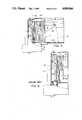
- FIG. 1is a vertical sectional view showing an embodiment of the invention
- FIG. 2is a cross sectional view of an essential portion of the same embodiment
- FIG. 3is a perspective view of an essential portion of a bill accumulating box in the same embodiment
- FIG. 4is a vertical sectional view showing a state where the reciprocating device has moved in a translational motion by a maximum distance in the embodiment of FIG. 1;
- FIG. 5is a vertical sectional view showing another embodiment of the invention.
- FIG. 6is a vertical sectional view showing a prior art device.
- FIG. 1shows an embodiment of a bill validator to which this invention has been applied.
- the main body of this bill validatorconsists of a vertical long casing.
- a bill insertion slit 1is formed in the lower portion of a front surface (left side surface as viewed in the figure).
- a billcan be inserted in the insertion slit 1 by lifting a cover 2.
- an L-shaped bill conveying passage 3communicating with the insertion slit 1 and conveying the bill in the longitudinal direction.
- magnetic heads H1 and H2In the short straight portion of this L-shaped bill conveying passage 3 nearer to insertion slit 1, there are provided magnetic heads H1 and H2 for discriminating a true bill from a false one.
- the magnetic heads H1 and H2constitute a pair across the center line and detect magnetic ingredient contained in the printing ink.
- a bill sensor S1for detecting the insertion of the bill.
- a conveying motor M1for driving these belts 4 and pulleys 5 and 6 transmitting rotation of this motor M1 to the belts 4.
- the rotation of the motor M1is transmitted to the upper pair of pulleys 5 and the lower pair of pulleys 6 are thereby driven.
- the lower pulleys 6are provided at the corner of the L-shape and the upper pulleys 5 are provided at the upper end of the L-shape.
- the belts 4extend over the longer straight portion from the corner of the L-shaped conveying passage 3 and the driving force is exercised to the bill in this section.
- a rotation pulse generator RPGwhich generates an electric pulse signal in synchronism with the rotational position of the conveying motor M1.
- This pulse signalis used for producing bill position address data when discrimination of a true bill from a false one is performed on the basis of outputs of the magnetic heads H1 and H2.
- the magnetism distribution on the surface of a billexhibits a specific pattern in correspondence to address positions on the bill and the discrimination of bills for each denomination can be made in accordance with this pattern.
- Reference characters R1, R2, R3 and R4respectively denote driven rollers.
- a reciprocating device for performing accumulation of billsis provided in the longer straight portion of the L-shaped conveying passage 3.
- This reciprocating devicecomprises a push plate 7 for pushing a bill conveyed on the conveying belts 4 in the direction of the surface of the bill and a mechanism for reciprocating this push plate 7 in accordance with rotation of a motor M2.
- a pair of eccentric cams 8mounted eccentrically on the rotation shaft of the motor M2 and a pair of link rods 11a and 11b which are pivotally connected in one end portions thereof to the push plate 7 and fixedly connected in the other end portions thereof to pins 10a and 10b through slots 9a and 9b.
- the cams 8are actuated to push the link rods 11a and 11b and the push plate 7 thereby is moved in translational movement in the direction of the surface of the plate.
- the push plate 7is constantly urged to the cams 8 by the force of a spring 21 so that the push plate 7 is moved in reciprocating motion in association with the eccentric movement of the cams 8.
- An accumulating box 12 for accumulating bills pushed by the reciprocating deviceis provided in the other straight portion of the L-shaped conveying passage 3.
- the accumulating box 12has its entrance formed by a vertically disposed pair of parallel elongated bill support channel members 13a and 13b which are spaced from each other with a space therebetween being somewhat narrower than the width of the bill.
- a bill compressing plate 14is provided in the accumulating box 12 in parallel to the channel members 13a and 13b and the push plate 7. This bill compressing plate 14 has breadth corresponding to the size of the bill. While the channel members 13a and 13b are stationary, the bill compressing plate 14 is movable in a translational motion in a normal direction to the surface of the plate.
- a part nearer to the conveying passage 3 of each of the channel members 13a and 13bis cut off and the driven rollers 16 and 17 are provided in the recesses. These rollers 16 and 17 are always urged towards the belt 4 by the force of the springs 18 and 19 so that these rollers 16 and 17 are rotated while holding the bill conveyed with the moving belts 4 between them and the belts 4.
- the reciprocating deviceIn a standby mode, the reciprocating device is in a state as shown in FIG. 1. In this state, the push plate 7 is in the furthest position from the accumulating box 12 and the space between this push plate 7 and the channel members 13a and 13b forms a passage for the bill.
- a lever 20is disposed at the corner of the L-shaped conveying passage 3 with an end portion thereof projecting in the passage 3.
- the lever 20is so constructed that it is pushed by a bill advancing in the forward direction (i.e., bill receiving direction) to withdraw automatically out of the passage but it functions as a stop against a bill moving in the reverse direction.
- a sensor S2is provided for detecting the motion of this lever 20. This sensor S2 is turned on when the lever 20 has been withdrawn out of the passage as shown by a chain-and-dot line 20' during advancing of the bill and it is turned off when the lever 20 has returned to the passage.
- the conveying motor M2Upon detection of insertion of a bill by the sensor S1, the conveying motor M2 is rotated forwardly to convey the inserted bill forwardly along the conveying passage 3. In the conveying process, validation of the bill is made on the basis of the outputs of the magnetic heads H1 and H2. If the bill is a false one, the motor M1 is reversely rotated to immediately return the bill to the depositor. If the bill has finally been judged to be a true bill and the rear end of the forwardly conveyed bill has passed by the lever 20 causing the sensor S2 to turn off from the on-state, a true bill signal is supplied to an outside device utilizing the bill validator and is used for counting the number of bills deposited.
- the forward rotation of the motor M1is stopped so that the inserted bill is stopped at a position in front of the push plate 7. Then the motor M2 is forwardly rotated to perform the bill accumulating operation for accumulating bills in the bill accumulating box 12.
- a carrier switch S3is mounted on the rotation shaft of the motor M2 so as to rotate the motor M2 by one rotation during the bill accumulating operation.
- the eccentric cams 8are rotated by one rotation and the push plate 7 thereby is moved in one reciprocating motion.
- FIG. 4shows a state where the reciprocating member has moved in translational motion by a maximum distance. In this state, the eccentric cams 8 have rotated by half rotation.
- the push plate 7returns in the direction of arrow A and the bill compressing plate 14 is pushed towards the channel members 13a and 13b by the force of the constant springs 15.
- the movement of the bill compressing plate 14is stopped and the bill is compressed and held between the members 13a and 13b and the bill compressing plate 14.
- the push plate 7is restored to the original position by the force of the spring 21, leaving the clamped bill in the box 12. In this manner, a number of bills 22 are accumulated between the channel members 13a and 13b in the box 12 and the bill compressing plate 14.
- the box 12By lifting a lid 24 mounted in the form of a latch as shown by reference character 24', the box 12 can be tilted as shown by reference character 12' about an unillustrated pivot and the accumulated bills can be readily taken out. It is also possible to exchange the box 12 by removing the tilted box 12 from the main body of the bill validator.
- An unillustrated safety switchis provided on the main body side in association with this box 12 for detecting that the box 12 has been tilted to the posture shown by 12' or has been removed from the main body thereby to stop driving of the motors M1 and M2 and prohibiting deposition of a bill during such tilting or removal of the box 12.
- fullness detection meansshould preferably be provided so that the rotation of the conveying motor M1 is stopped when the full state of the accumulation box has been detected or the motor M1 is reversely rotated to automatically return a deposited bill when the sensor S1 at the insertion slit 1 has detected the bill.
- fullness detection meansfor example, a sensor may be provided at a suitable fullness detecting position in the box 12 or some means may be provided for detecting that the number of bills has reached a set maximum number by detecting that a load exceeding a predetermined value has been applied to the accumulating motor M2.
- such application of a load exceeding a predetermined value to the motor M2can be detected by detecting whether or not the carrier switch S3 has maintained the on state for more than a predetermined length of time. That is, when the accumulated number of bills has reached the maximum, the bill compressing plate 14 does not move in the direction of arrow A further and the rotation of the motor M2 is thereupon interrupted. In this case, the motor M2 may be reversely rotated to the standby state shown in FIG. 1.
- FIG. 5shows an example in which the mounting places of the winding shafts 15a of the constant springs 15 have been changed.
- the winding shafts 15a of the constant springs 15are provided at locations which are relatively spaced from the channel members 13a and 13b.
- the connecting portions 14b provided on the left and right sides and the lower surface of the bill compressing plate 14have a sufficient length for connecting the takeout ends of the springs 15.
- the distance between the surface of the bill compressing plate 14 and the spring takeout end connecting positions in the connecting portions 14bis equivalent to the distance between the spring winding shafts 15a and the channel members 13a and 13b.
- the connecting portions 14b shown in FIG. 5are longer than the connecting portions 14a shown in FIG. 1 and, in proportion thereto, the accumulating box 120 is a larger one than the accumulating box 12 shown in FIG. 1.
- there are provided four constant springsi.e., two on the left and right sides and two on the lower surface.
- the number of the constant springshowever is not limited to four but it may be two, three or five or more. It is not necessary for all of the constant springs 15 to support a bill by engaging with the periphery of the bill but only a part of the constant springs, e.g., the constant springs on the lower surface, may support the bill.
Landscapes
- Engineering & Computer Science (AREA)
- Mechanical Engineering (AREA)
- Physics & Mathematics (AREA)
- General Physics & Mathematics (AREA)
- Pile Receivers (AREA)
- Control Of Vending Devices And Auxiliary Devices For Vending Devices (AREA)
Abstract
Description
Claims (2)
Applications Claiming Priority (2)
| Application Number | Priority Date | Filing Date | Title |
|---|---|---|---|
| JP61-57161 | 1986-03-17 | ||
| JP61057161AJPH0742028B2 (en) | 1986-03-17 | 1986-03-17 | Banknote storage device |
Publications (1)
| Publication Number | Publication Date |
|---|---|
| US4809966Atrue US4809966A (en) | 1989-03-07 |
Family
ID=13047837
Family Applications (1)
| Application Number | Title | Priority Date | Filing Date |
|---|---|---|---|
| US07/025,401Expired - LifetimeUS4809966A (en) | 1986-03-17 | 1987-03-13 | Bill validator having constant spring bill accumulation mechanism |
Country Status (3)
| Country | Link |
|---|---|
| US (1) | US4809966A (en) |
| JP (1) | JPH0742028B2 (en) |
| KR (1) | KR910009307B1 (en) |
Cited By (36)
| Publication number | Priority date | Publication date | Assignee | Title |
|---|---|---|---|---|
| US5056432A (en)* | 1989-01-24 | 1991-10-15 | Tokyo Electric Company, Ltd. | Printer with sheet feeding apparatus |
| US5076413A (en)* | 1990-07-13 | 1991-12-31 | General Signal Corporation | Multiple bill escrow and storage apparatus |
| US5083761A (en)* | 1988-08-31 | 1992-01-28 | Minolta Camera Kabushiki Kaisha | Sheet storing apparatus for sheets ejected from a copying machine |
| US5096038A (en)* | 1989-08-16 | 1992-03-17 | De La Rue Systems Limited | Thread detector assembly |
| US5195739A (en)* | 1991-02-01 | 1993-03-23 | Nippon Conlux Co., Ltd. | Apparatus for preventing bills or the like from being pulled out |
| US5288066A (en)* | 1992-04-10 | 1994-02-22 | Ncr Corporation | Apparatus and method for loading sheets into a receptacle |
| EP0570251A3 (en)* | 1992-04-27 | 1994-09-14 | Roll Systems Inc | Web stacker and separator |
| US5372361A (en)* | 1992-11-13 | 1994-12-13 | Japan Cash Machine Co. Ltd. | Bill handling apparatus with exchangeable pusher for stacker |
| US5377805A (en)* | 1992-05-29 | 1995-01-03 | Nippon Conlux Co., Ltd. | Bill discriminating apparatus |
| US5388817A (en)* | 1993-10-06 | 1995-02-14 | Gameax Corporation | Note stacker mechanism |
| WO1995013236A1 (en)* | 1993-11-12 | 1995-05-18 | Opex Corporation | Remittance processing apparatus and method |
| US5419423A (en)* | 1992-12-03 | 1995-05-30 | Kabushiki Kaisha Nippon Conlux | Paper money processor |
| US5421443A (en)* | 1992-11-05 | 1995-06-06 | Kabushiki Kaisha Nippon Conlux | Bill processing unit |
| US5454557A (en)* | 1992-01-29 | 1995-10-03 | Fuji Photo Film Co., Ltd. | Film accumulator and film accumulator/holder |
| US5505439A (en)* | 1993-05-11 | 1996-04-09 | Kabushiki Kaisha Nippon Conlux | Bill processor |
| US5564691A (en)* | 1993-11-05 | 1996-10-15 | Kabushiki Kaisha Nippon Conlux | Bill processor |
| US5605214A (en)* | 1992-07-29 | 1997-02-25 | Kabushiki Kaisha Nippon Conlux | Banknote processor |
| US5709293A (en)* | 1994-03-10 | 1998-01-20 | Kabushiki Kaisha Nippon Conlux | Bill processing device |
| US5756985A (en)* | 1996-04-04 | 1998-05-26 | Coin Acceptors, Inc. | Cash box system for bill validator |
| US5803227A (en)* | 1995-06-06 | 1998-09-08 | International Game Technology | Bill stacker |
| US5829673A (en)* | 1996-04-04 | 1998-11-03 | Coin Acceptors, Inc. | Modular cash box |
| USD404075S (en) | 1996-01-11 | 1999-01-12 | Kabushiki Kaisha Nippon Conlux | Bill validator |
| US5876033A (en)* | 1995-06-26 | 1999-03-02 | Officina Meccanica L.A.R. Di Lonati Lorenzo & C. S.N.C. | Device to stack and collect banknotes with the possibility of returning them |
| US6199856B1 (en) | 1998-01-07 | 2001-03-13 | Robert Clauser | Flexible media stacking and accumulating device |
| US6244589B1 (en) | 1998-06-23 | 2001-06-12 | Mars Incorporated | Banknote stacking apparatus |
| US6546881B1 (en) | 2001-08-29 | 2003-04-15 | Coin Acceptors, Inc. | Expandable cash box |
| US20030126022A1 (en)* | 2001-12-17 | 2003-07-03 | Shang-Ter Chou | Paper currency collection detection arrangement for an automatic vending machine |
| EP1387327A1 (en)* | 2002-07-31 | 2004-02-04 | Jofemar, S.A. | Bank note validation and storage apparatus |
| EP1471021A1 (en)* | 2003-04-23 | 2004-10-27 | Aruze Corporation | Sheet handling apparatus |
| US20050023341A1 (en)* | 2003-07-29 | 2005-02-03 | Yukie Taniyama | Bill handling apparatus |
| US20050225026A1 (en)* | 2001-12-28 | 2005-10-13 | Cost Evan J | Sheet stacking apparatus |
| US20050234589A1 (en)* | 2002-05-15 | 2005-10-20 | Tadashi Hatamachi | Bill processing device |
| US20070001384A1 (en)* | 2005-06-17 | 2007-01-04 | Aruze Corp. | Bill processor |
| WO2008047094A3 (en)* | 2006-10-18 | 2008-10-30 | Rue De Int Ltd | Document handling apparatus |
| EP2963623A1 (en)* | 2014-07-04 | 2016-01-06 | Wincor Nixdorf International GmbH | Money box with a movable base tray |
| US9994409B1 (en)* | 2017-02-17 | 2018-06-12 | Masterwork Automodules Technology Corp., Ltd | Document storage assembly |
Families Citing this family (4)
| Publication number | Priority date | Publication date | Assignee | Title |
|---|---|---|---|---|
| JP3658268B2 (en)* | 2000-03-01 | 2005-06-08 | 日立オムロンターミナルソリューションズ株式会社 | Paper sheet stacking device, paper sheet storage, and paper sheet handling device |
| JP4559647B2 (en)* | 2001-03-21 | 2010-10-13 | 株式会社サトー | Stacker and control method thereof |
| JP2006244367A (en)* | 2005-03-07 | 2006-09-14 | Fuji Electric Retail Systems Co Ltd | Vending machine |
| CN101659358B (en)* | 2008-08-27 | 2012-03-28 | 鸿富锦精密工业(深圳)有限公司 | Paper pressing device |
Citations (8)
| Publication number | Priority date | Publication date | Assignee | Title |
|---|---|---|---|---|
| DE230648C (en)* | ||||
| US1166017A (en)* | 1914-11-07 | 1915-12-28 | Joseph E Smyth Company | Stacker mechanism. |
| US2659907A (en)* | 1952-08-20 | 1953-11-24 | Donnelley & Sons Co | Machine for forming bundles of signatures |
| US3148879A (en)* | 1961-08-31 | 1964-09-15 | Ibm | Stacking apparatus |
| US3655186A (en)* | 1970-12-14 | 1972-04-11 | Ardac Inc | Stacker for paper currency |
| US3811549A (en)* | 1973-05-10 | 1974-05-21 | Bobst Fils Sa J | Apparatus for handling a flow of boxes |
| JPS5227700A (en)* | 1975-03-31 | 1977-03-02 | Takamisawa Saibaneteitsukusu:Kk | Paper money housing device in changer or the like |
| US4474366A (en)* | 1983-01-03 | 1984-10-02 | Avery International Corporation | Article stacking machine |
- 1986
- 1986-03-17JPJP61057161Apatent/JPH0742028B2/ennot_activeExpired - Lifetime
- 1987
- 1987-03-02KRKR1019870001818Apatent/KR910009307B1/ennot_activeExpired
- 1987-03-13USUS07/025,401patent/US4809966A/ennot_activeExpired - Lifetime
Patent Citations (8)
| Publication number | Priority date | Publication date | Assignee | Title |
|---|---|---|---|---|
| DE230648C (en)* | ||||
| US1166017A (en)* | 1914-11-07 | 1915-12-28 | Joseph E Smyth Company | Stacker mechanism. |
| US2659907A (en)* | 1952-08-20 | 1953-11-24 | Donnelley & Sons Co | Machine for forming bundles of signatures |
| US3148879A (en)* | 1961-08-31 | 1964-09-15 | Ibm | Stacking apparatus |
| US3655186A (en)* | 1970-12-14 | 1972-04-11 | Ardac Inc | Stacker for paper currency |
| US3811549A (en)* | 1973-05-10 | 1974-05-21 | Bobst Fils Sa J | Apparatus for handling a flow of boxes |
| JPS5227700A (en)* | 1975-03-31 | 1977-03-02 | Takamisawa Saibaneteitsukusu:Kk | Paper money housing device in changer or the like |
| US4474366A (en)* | 1983-01-03 | 1984-10-02 | Avery International Corporation | Article stacking machine |
Non-Patent Citations (2)
| Title |
|---|
| "Stacker-Reader Sorter", F. W. Doolittle et al., IBM Technical Disclosure Bulletin, vol. 13, No. 10, Mar. 1971, pp. 3109-3110. |
| Stacker Reader Sorter , F. W. Doolittle et al., IBM Technical Disclosure Bulletin, vol. 13, No. 10, Mar. 1971, pp. 3109 3110.* |
Cited By (54)
| Publication number | Priority date | Publication date | Assignee | Title |
|---|---|---|---|---|
| US5083761A (en)* | 1988-08-31 | 1992-01-28 | Minolta Camera Kabushiki Kaisha | Sheet storing apparatus for sheets ejected from a copying machine |
| US5056432A (en)* | 1989-01-24 | 1991-10-15 | Tokyo Electric Company, Ltd. | Printer with sheet feeding apparatus |
| US5096038A (en)* | 1989-08-16 | 1992-03-17 | De La Rue Systems Limited | Thread detector assembly |
| US5076413A (en)* | 1990-07-13 | 1991-12-31 | General Signal Corporation | Multiple bill escrow and storage apparatus |
| US5195739A (en)* | 1991-02-01 | 1993-03-23 | Nippon Conlux Co., Ltd. | Apparatus for preventing bills or the like from being pulled out |
| US5454557A (en)* | 1992-01-29 | 1995-10-03 | Fuji Photo Film Co., Ltd. | Film accumulator and film accumulator/holder |
| US5288066A (en)* | 1992-04-10 | 1994-02-22 | Ncr Corporation | Apparatus and method for loading sheets into a receptacle |
| EP0570251A3 (en)* | 1992-04-27 | 1994-09-14 | Roll Systems Inc | Web stacker and separator |
| US5558319A (en)* | 1992-04-27 | 1996-09-24 | Roll Systems, Inc. | Web stacker and separator with sheet offsetting kicker |
| US5377805A (en)* | 1992-05-29 | 1995-01-03 | Nippon Conlux Co., Ltd. | Bill discriminating apparatus |
| US5605214A (en)* | 1992-07-29 | 1997-02-25 | Kabushiki Kaisha Nippon Conlux | Banknote processor |
| US5421443A (en)* | 1992-11-05 | 1995-06-06 | Kabushiki Kaisha Nippon Conlux | Bill processing unit |
| US5372361A (en)* | 1992-11-13 | 1994-12-13 | Japan Cash Machine Co. Ltd. | Bill handling apparatus with exchangeable pusher for stacker |
| US5419423A (en)* | 1992-12-03 | 1995-05-30 | Kabushiki Kaisha Nippon Conlux | Paper money processor |
| US5505439A (en)* | 1993-05-11 | 1996-04-09 | Kabushiki Kaisha Nippon Conlux | Bill processor |
| US5388817A (en)* | 1993-10-06 | 1995-02-14 | Gameax Corporation | Note stacker mechanism |
| US5887695A (en)* | 1993-11-05 | 1999-03-30 | Kabushiki Kaisha Nippon Conlux | Bill processor |
| US5564691A (en)* | 1993-11-05 | 1996-10-15 | Kabushiki Kaisha Nippon Conlux | Bill processor |
| US5639081A (en)* | 1993-11-05 | 1997-06-17 | Kabushiki Kaisha Nippon Conlux | Bill processor |
| US5443253A (en)* | 1993-11-12 | 1995-08-22 | Omation Corporation | Remittance processing apparatus and method |
| WO1995013236A1 (en)* | 1993-11-12 | 1995-05-18 | Opex Corporation | Remittance processing apparatus and method |
| US6076648A (en)* | 1994-03-10 | 2000-06-20 | Kabushiki Kaisha Nippon Conlux | Bill processing device |
| US5709293A (en)* | 1994-03-10 | 1998-01-20 | Kabushiki Kaisha Nippon Conlux | Bill processing device |
| US5803227A (en)* | 1995-06-06 | 1998-09-08 | International Game Technology | Bill stacker |
| US5876033A (en)* | 1995-06-26 | 1999-03-02 | Officina Meccanica L.A.R. Di Lonati Lorenzo & C. S.N.C. | Device to stack and collect banknotes with the possibility of returning them |
| USD404075S (en) | 1996-01-11 | 1999-01-12 | Kabushiki Kaisha Nippon Conlux | Bill validator |
| US5829673A (en)* | 1996-04-04 | 1998-11-03 | Coin Acceptors, Inc. | Modular cash box |
| US5756985A (en)* | 1996-04-04 | 1998-05-26 | Coin Acceptors, Inc. | Cash box system for bill validator |
| US6199856B1 (en) | 1998-01-07 | 2001-03-13 | Robert Clauser | Flexible media stacking and accumulating device |
| US6244589B1 (en) | 1998-06-23 | 2001-06-12 | Mars Incorporated | Banknote stacking apparatus |
| US6546881B1 (en) | 2001-08-29 | 2003-04-15 | Coin Acceptors, Inc. | Expandable cash box |
| US6851540B2 (en)* | 2001-12-17 | 2005-02-08 | International Currency Technologies Corporation | Paper currency collection detection arrangement for an automatic vending machine |
| US20030126022A1 (en)* | 2001-12-17 | 2003-07-03 | Shang-Ter Chou | Paper currency collection detection arrangement for an automatic vending machine |
| US20050225026A1 (en)* | 2001-12-28 | 2005-10-13 | Cost Evan J | Sheet stacking apparatus |
| US7172193B2 (en) | 2001-12-28 | 2007-02-06 | Mei, Inc. | Sheet stacking apparatus |
| US6966555B2 (en) | 2001-12-28 | 2005-11-22 | Mars Incorporated | Sheet stacking apparatus |
| US20050234589A1 (en)* | 2002-05-15 | 2005-10-20 | Tadashi Hatamachi | Bill processing device |
| ES2214949B2 (en)* | 2002-07-31 | 2006-02-01 | Jofemar, S.A. | APPLIANCE FOR VALIDATION AND STORAGE OF TICKETS. |
| AU2003221460B2 (en)* | 2002-07-31 | 2009-04-23 | Jofemar, S.A. | Bank note validation and storage apparatus |
| ES2214949A1 (en)* | 2002-07-31 | 2004-09-16 | Jofemar, S.A. | Apparatus for bank note validation and storage |
| EP1387327A1 (en)* | 2002-07-31 | 2004-02-04 | Jofemar, S.A. | Bank note validation and storage apparatus |
| US7255341B2 (en) | 2003-04-23 | 2007-08-14 | Aruze Corp. | Sheet handling apparatus |
| EP1471021A1 (en)* | 2003-04-23 | 2004-10-27 | Aruze Corporation | Sheet handling apparatus |
| US20040212143A1 (en)* | 2003-04-23 | 2004-10-28 | Kazuei Yoshioka | Sheet handling apparatus |
| US20050023341A1 (en)* | 2003-07-29 | 2005-02-03 | Yukie Taniyama | Bill handling apparatus |
| US7357303B2 (en)* | 2003-07-29 | 2008-04-15 | Hitachi-Omron Terminal Solutions, Corp. | Bill handling apparatus |
| US20070001384A1 (en)* | 2005-06-17 | 2007-01-04 | Aruze Corp. | Bill processor |
| EA009270B1 (en)* | 2005-06-17 | 2007-12-28 | Арузе Корп. | Bill handling device |
| WO2008047094A3 (en)* | 2006-10-18 | 2008-10-30 | Rue De Int Ltd | Document handling apparatus |
| US20100052237A1 (en)* | 2006-10-18 | 2010-03-04 | Lars Karoly Herczeg | Document handling apparatus |
| US20110233855A1 (en)* | 2006-10-18 | 2011-09-29 | Talaris Holdings Limited | Document handling apparatus |
| EP2963623A1 (en)* | 2014-07-04 | 2016-01-06 | Wincor Nixdorf International GmbH | Money box with a movable base tray |
| US9454862B2 (en) | 2014-07-04 | 2016-09-27 | Wincor Nixdorf International Gmbh | Cash box having a movable base tray |
| US9994409B1 (en)* | 2017-02-17 | 2018-06-12 | Masterwork Automodules Technology Corp., Ltd | Document storage assembly |
Also Published As
| Publication number | Publication date |
|---|---|
| JPH0742028B2 (en) | 1995-05-10 |
| KR870009310A (en) | 1987-10-24 |
| KR910009307B1 (en) | 1991-11-09 |
| JPS62215461A (en) | 1987-09-22 |
Similar Documents
| Publication | Publication Date | Title |
|---|---|---|
| US4809966A (en) | Bill validator having constant spring bill accumulation mechanism | |
| US4678072A (en) | Bill validating and accumulating device | |
| US4765607A (en) | Stacker apparatus | |
| US7422095B2 (en) | Bill handling device and bill accommodating unit | |
| US6948607B2 (en) | Sheet handling apparatus and method for opening/closing sheet transport path in the handling apparatus | |
| EP1465123B1 (en) | Currency cassette pressure plate assembly | |
| US6254083B1 (en) | Leaf transfer mechanism unit | |
| JP3579230B2 (en) | Sheet material guiding device | |
| JP2908525B2 (en) | Bill / card identification device | |
| JP3765850B2 (en) | Banknote handling equipment | |
| JP3719685B2 (en) | Shutter device for paper sheet transport path | |
| JPH0718660Y2 (en) | Banknote conveyor | |
| JPH0644439A (en) | Device for paper money | |
| JPH0437474B2 (en) | ||
| JP4559166B2 (en) | A bill withdrawal prevention mechanism for bill validators | |
| JP2600133Y2 (en) | Banknote storage device | |
| JPH0377553B2 (en) | ||
| JPH0778280A (en) | Carrier and storage device of papaer money | |
| KR19980073042A (en) | Banknote stacking device | |
| JPH0434197B2 (en) | ||
| JPH09167264A (en) | Ticket kind discriminating | |
| JPH0246991B2 (en) | ||
| HK1006963B (en) | Improved stacker apparatus | |
| JPH0641353B2 (en) | Banknote storage device |
Legal Events
| Date | Code | Title | Description |
|---|---|---|---|
| AS | Assignment | Owner name:KABUSHIKI KAISHA NIPPON COINCO, 2-2, UCHISAIWAICHO Free format text:ASSIGNMENT OF ASSIGNORS INTEREST.;ASSIGNORS:KOBAYASHI, OSAMU;HAYASHI, HIROSHI;REEL/FRAME:004679/0378 Effective date:19870227 | |
| STCF | Information on status: patent grant | Free format text:PATENTED CASE | |
| AS | Assignment | Owner name:NIPPON CONLUX CO., LTD., JAPAN Free format text:CHANGE OF NAME;ASSIGNOR:KABUSHIKI KAISHA NIPPON COINCO;REEL/FRAME:005036/0290 Effective date:19880903 | |
| FEPP | Fee payment procedure | Free format text:PAYOR NUMBER ASSIGNED (ORIGINAL EVENT CODE: ASPN); ENTITY STATUS OF PATENT OWNER: LARGE ENTITY | |
| FPAY | Fee payment | Year of fee payment:4 | |
| FPAY | Fee payment | Year of fee payment:8 | |
| FPAY | Fee payment | Year of fee payment:12 | |
| AS | Assignment | Owner name:CITIBANK, N.A., TOKYO BRANCH, JAPAN Free format text:SECURITY AGREEMENT;ASSIGNOR:NIPPON CONLUX CO., LTD.;REEL/FRAME:017957/0752 Effective date:20060719 | |
| AS | Assignment | Owner name:NIPPON CONLUX CO., LTD., JAPAN Free format text:CHANGE OF NAME;ASSIGNOR:AP6 CO., LTD.;REEL/FRAME:018679/0787 Effective date:20060930 Owner name:AP6 CO., LTD., JAPAN Free format text:MERGER;ASSIGNOR:NIPPON CONLUX CO., LTD.;REEL/FRAME:018679/0741 Effective date:20060930 | |
| AS | Assignment | Owner name:CITIBANK JAPAN LTD., JAPAN Free format text:CHANGE OF SECURITY AGENT;ASSIGNOR:CITIBANK, N.A., TOKYO BUILDING;REEL/FRAME:019704/0952 Effective date:20070701 |