US4809725A - Telescopic crutch and walking stick - Google Patents
Telescopic crutch and walking stickDownload PDFInfo
- Publication number
- US4809725A US4809725AUS07/003,865US386587AUS4809725AUS 4809725 AUS4809725 AUS 4809725AUS 386587 AUS386587 AUS 386587AUS 4809725 AUS4809725 AUS 4809725A
- Authority
- US
- United States
- Prior art keywords
- tube
- tubes
- walking stick
- aligned holes
- crutch
- Prior art date
- Legal status (The legal status is an assumption and is not a legal conclusion. Google has not performed a legal analysis and makes no representation as to the accuracy of the status listed.)
- Expired - Lifetime
Links
Images


Classifications
- A—HUMAN NECESSITIES
- A61—MEDICAL OR VETERINARY SCIENCE; HYGIENE
- A61H—PHYSICAL THERAPY APPARATUS, e.g. DEVICES FOR LOCATING OR STIMULATING REFLEX POINTS IN THE BODY; ARTIFICIAL RESPIRATION; MASSAGE; BATHING DEVICES FOR SPECIAL THERAPEUTIC OR HYGIENIC PURPOSES OR SPECIFIC PARTS OF THE BODY
- A61H3/00—Appliances for aiding patients or disabled persons to walk about
- A61H3/02—Crutches
- A61H2003/0233—Crutches convertible from armpit crutch into cane
Definitions
- the present inventionrelates to a telescopic combined crutch and walking stick.
- Crutches or walking sticks made of metal tubings and comprising one or more telescopic portions to make them adjustable as to length to suit persons of different heights,are well known in the art and commonly available almost everywhere.
- crutches made of a sufficient number of telescopic tubings to make them easily collapsible and compressible to such an extent that they can, when not in use, be conveniently put away and packed into a suitcase and, when required for use, be very easily extended in operative positionare also known.
- British Patent No. 122,694 to Kellydiscloses such a crutch made of several lengths of tubing telescoping into each other so that they can be extended or contracted.
- a first object of the present inventionis to provide a combined crutch and walking stick which may not only be rapidly and easily converted from one use to the other and vice-versa like the article disclosed in U.S. Pat. No. 2,960,095, but which may also be rapidly and sufficiently collapsed to be insertable in a small piece of luggage, such as a brief case, while yet being extensible adjustably to suit the height of any average crutch user.
- Another object of the present inventionis to provide an article of the above mentioned type, wherein all the telescopically adjustable lengths of tubing are slidably and non-rotatably mounted inside the others, and wherein all but one of a plurality of selectable positions in each adjustable length may be blocked by the user after suitable adjustment to his or her physical requirements.
- these featuresmay advantageously be achieved by the provision of flattened sections formed on the telescoping tubes, which sections face one another and thereby prevent relative rotation between the tubes and thus any misalignment of the holes of the tubes, and by the provision of blocking means such as resilient rings or strips attachable to the tube walls for blocking all but one of the aligned holes of each tube.
- blocking meanssuch as resilient rings or strips attachable to the tube walls for blocking all but one of the aligned holes of each tube.
- a further object of the present inventionis to provide an article of the above mentioned type, wherein the armpit and the handle are each provided with cushioning sleeves made of flexible material, preferably rubber, which sleeves have an outwardly tapering shape making them particularly suitable for hanging the combined crutch and walking stick to a shelf or from a table with the handle resting on the flat surface of the table.
- Still another object of the inventionis to provide an article of the above type which is quite simple in construction so that it can be produced at a relatively low cost.
- the telescopic, combined crutch and walking stick according to the inventionbasically comprises:
- first locking means in the middle tubefor positioning this middle tube in the lower tube in one of several selectable positions
- second locking meansin the upper tube for positioning the upper tube in the middle tube in one of several selectable positions
- a walking stick handlemounted at the upper end of the middle tube.
- the lower, middle and upper tubesare of a length such that, when they are fully retracted one into the other, the length of the combined crutch and stick is about 1/3 the length thereof when fully extended.
- the middle and lower tubeare each formed with aligned holes passing through and spaced along their walls.
- the first locking means used for positioning the middle tube in the lower tubecomprises a first detent knob transversally extending inside of and at the lower end of the middle tube, and spring means for resiliently pressing this first knob into one of these aligned holes of the lower tube when in registry therewith.
- the second locking means used for positioning the upper tube in the middle tubecomprises a second detent knob transversally extending inside of and at the lower end of the upper tube, and spring for means resiliently pressing said second knob into one of the aligned holes of the middle tube when in registry therewith.
- the combined crutch and walking stickfurther comprises means for preventing relative rotation of the lower middle and upper tubes and means for blocking all but one of the aligned holes of both the lower and middle tube.
- the rotation preventing meansmay preferably consist of flattened sections provided in the lower, middle and upper tubes, these flattened sections facing one another. In such a case, the aligned holes of the lower and middle tubes are respectively formed through the flattened sections of these lower and middle tubes.
- the blocking meansmay comprise resilient rings removably lodged into the grooves of all of the holes but one, for blocking entry of the detent knobs.
- the blocking meansmay comprise flat strips slid in the grooves, these strips having essentially the same length as the middle and lower tubes, respectively, and being each provided with a single hole positioned so as to register with a preselected hole of the corresponding middle r lower tube thereby to allow the corresponding detent knob to move only into the preselected hole when the tubes are adjusted with respect to each other.
- the combined crutch and walking stickis so designed that the aligned holes of the middle tube are evenly spaced from one another; the aligned holes of the lower tube are evenly spaced from one another; and the spacing between the aligned holes of either of the middle and lower tubes is greater than the spacing between the aligned holes of the other tube.
- the armpit supportcomprises a T-shaped member having a transverse armpit rest; a pair of free ends; a central cavity extending perpendicularly into the armpit rest, the cavity being sized to fit over the upper end of the upper tube; and means such as a screw, for detachably fixing the armpit rest onto the upper end of the upper tube when this upper end is fitted in the cavity.
- a pair of cushioning sleeves made of flexible materialare force-fitted over the T-shaped member from the free ends thereof toward the central cavity. These sleeves which act as cushions each have a cross-section evenly increasing in size from the central cavity to the free ends of the T-shaped member.
- a similar cushioning sleevemay also or alternatively be force-fitted over the handle to make it easy to grip in addition of making the walking stick easily hangable to a table.
- the first locking meansare preferably mounted in a small well, provided in a first plug made of plastic material and fixed to the lower end of the middle tube.
- the second locking meansare preferably mounted in a small well, provided in a second plug made of plastic material and fixed to the lower end of the upper tube, these first and second plugs being each provided with an outwardly projecting skirt for slidably guiding the lower ends of the middle and upper tubes centrally inside the lower and middle tubes, respectively.
- FIGS. 1a and 1bare side and front elevational views, respectively, of a combined crutch and walking stick made according to the teaching of the invention, shown in fully extended condition;
- FIG. 2is a view similar to that of FIG. 1 but with the combined crutch and walking stick in fully collapsed or retracted condition;
- FIG. 3is an exploded, side elevational view similar to that of FIG. 1, showing most of the parts in longitudinal cross-section;
- FIG. 4is an elevational partial cross-section view showing interengagement of two telescoping tubes
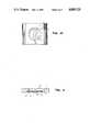
- FIG. 5is a transverse cross-sectional view of the combined crutch and walking stick taken through the handle thereof;
- FIG. 6appearing on the same sheet of drawing as FIG. 3, is a side elevational cross-sectional view of the upper part of the upper tube and the armpit rest attached thereto, and of the upper part of the middle tube and the handle attached thereto;
- FIG. 7is a side elevation view of a portion of the lower tube intended to show its flattened section
- FIG. 8is a transverse cross-sectional view through the telescoping middle and lower tubes
- FIG. 9appearing on the same sheet of drawings as FIGS. 4 and 5 is a tranverse, cross-section view of a tube, showing the bottom of the other tube telescopically mounted therein;
- FIG. 10is a front elevational view, on a greatly enlarged scale, of a portion of the lower tube
- FIG. 11is a cross-sectional view, on an enlarged scale, through a portion of the lower tube, this view being intended to illustrate a variant of the invention
- FIG. 12appearing on the same sheet of drawings as FIGS. 3 and 6, is a partial, bottom view of the central portion of the armpit rest.
- FIG. 13appearing on the same sheet of drawings as FIGS. 4 and 5, is a top plan view of the combined crutch and walking stick, showing a possible adjustment of the armpit rest with respect to the handle.
- the telescopic collapsable combined crutch and walking stick or caneas shown in the accompanying drawings comprises a lower ground engaging tube 1, a middle tube 3 telescopically slidable inside the lower tube 1 and an upper tube 5 slidably and telescopically received within the middle tube 3 and having, at its upper free end, an armpit support 7.
- a walking stick handle 9is provided at the upper end of the middle tube 3.
- the lower end of the lower tube 1has a ground-engaging rubber pad or foot 11 which may be removably mounted on the end of the lower tube 1.
- tubes 1, 3 and 5are of a length such that when they are retracted one into the other, as shown in FIG. 2, the overall length of the combined crutch and stick is about 1/3 the length when fully extended. In other words, tubes 1, 3 and 5 have approximatively the same length.
- the middle tube 3 as well as the lower tube 1are each formed with a series of holes 13, 15, respectively, that extend through and are spaced along the wall of the tubes.
- first locking meansare provided at the bottom end of the middle tube 3 for positioning this tube in the lower tube 1 in one of serial selectable position.
- These first locking meanscomprises a first plug 14 made of plastic material, which plug has one end force-fitted into the tube 3 and the other end provided with a transversal well 16 oriented in such a manner as to face the aligned holes 15 of the first tube.
- a first detent knob 17is slidably mounted inside the well 16. This knob 17 has a shoulder 19 larger than the hole 15 whereby to prevent it from escaping out of the middle tube 3.
- a spring 21resiliently presses the knob 17 into one of the holes 15 and holds it there by engagement of the shoulder 19 with the inner wall of the middle tube 3.
- the knob 17has a length which is sufficient for it to enter into any of the holes 15 of the lower tube 1 when one of those holes 15 registers with it. It will thus be appreciated that by pushing the knob 17 inward and out of engagement with one hole 15, it is possible to slide the middle tube 3 with respect to lower tube 1 until a further hole 15 is reached.
- second locking means similar to the first oneare provided in a second plug 14' similar to the first one at the lower end of the upper tube 5.
- the holes of the middle and lower tubes 3 and 1may be evenly spaced from one another. However, as shown in FIG. 1b, in order to afford a better selection as to the length of the combination, the spacing between the holes of one of the tubes is preferably made wider than the spacing between the holes of the other tube.
- FIG. 8A rotation-preventing means that can be used in accordance with the invention is best illustrated in FIG. 8 showing the telescoping tubes 1 and 3 but in transverse cross-section rather than the longitudinal cross-section of FIG. 3. It will be seen that the tubes 1 and 3 are provided with flattened sections 1' and 3' facing one another thereby preventing relative rotation.
- the upper tube 5is likewise provided with a flattened section, not shown. Holes 13 and 15 extend centrally of and through the flattened sections 1' and 3'.
- FIGS. 7, 8 and 10A positive manner of attaining the desired length relationship between the tubes 1 and 3 is shown in FIGS. 7, 8 and 10. This manner resides in blocking all undesired holes 13 or 15 to prevent entry of the detent knob 17, 17', leaving free for entry of the detent knobs 17, 17', only the one hole 13 or 15 of each of tubes 3 and 1 that will give the proper preselected length relationship of tubes 1, 3 and 5.
- FIGS. 8 and 10The above hole blocking means is best illustrated in FIGS. 8 and 10 for telescoping tubes 1 and 3. It will be appreciated that a similar principle applies to the tubes 3 and 5.
- the holes 15are each formed with an arcuate groove 18 extending partially around the hole 15 (see FIG. 10).
- a resilient ring 20, or circlipReceived in the groove 18 is a resilient ring 20, or circlip, having a portion of its periphery inwardly turned to form an U-shaped stop 22 blocking most of the central portion of the ring 20. Inserting of the ring into a hole 15 can be carried out by gripping the arms of the U-shaped stop 22 and bringing them toward one another to reduce the diameter of the ring 20 which is then properly positioned over the groove 18. Release of the arms of the stop 22 allows the ring to expand out and lodge itself in the groove 18. As shown in FIG. 10, the groove 18 does not extend the full periphery of the hole 15. The non-grooved portion of this periphery is located in the lower part of the hole 15 to provide a larger bearing surface for the knob 17 and thus prevent this knob from wear.
- the stop 22after insertions of the ring, extends across the hole 15 and has prevents the knob 17 to enter this hole.
- FIG. 11Another form of blocking means is shown in FIG. 11.
- the holes 15open inwardly into a slide groove 24 formed fully lengthwise of the flattened section or land 1' of the tube 1 and delimited inwardly by a pair of facing shoulders 26 and 26'.
- this straight groove 24borders the holes 15 of tube 1.
- a flat strip 20, having essentially the same length as the tube 1is slid into the inward groove 24 and is stopped downwardly by the top surface of foot pad 11 (FIG. 3).
- the corresponding stripmay be stopped downwardly by the top surface of the plug 14.
- such a stoppingmay be achieved by the provision of a small internal projection 54 (FIG.
- a similar projectionmay also be provided on top of each tube to prevent the inserted strip 28 from moving up when the crutch is extended.
- a lateral hole(not shown) may be provided in the tubes 1 and 3 near the top of the strip to allow insertion of a pin for use in disengaging the strip from its groove 24 over the projection 54 in the case this strip has to be changed or readjusted.
- the strip 28which may be made of plastic material, is provided with a single hole and with a series of transversal tear lines (not shown) distributed and spaced along its length to make it possible to cut it to one given length where the hole of the strip will register with one preselected hole 15.
- the strip 28is adjusted in length and positioned in its groove 24, its hole will allow the detent knob 17 to enter only the preselected hole 15. Accordingly, the detent knob 17 will move only into that hole 15 which has thus been freed.
- the same constructionapplies as aforesaid to the tube 3 with respect to the detent knob 17' of the tube 5.
- the upper end of the upper tube 5is provided with an armpit support 7 which, as shown in FIG. 3, comprises a T-shaped member 39 provided with a pair of free ends 41, 41'.
- the central portion of the member 39is provided with downwardly opening cavity 43 extending perpendicularly these to.
- the cavity 43is sized and shaped to fit over a plug 45 held in the upper end of the upper tube 5.
- the plug 45has a semi spherical top shaped to fit in the cavity 43, and cylindrical bottom provided with an pseudo-annular groove 47 in which the upper end of the tube 5 may be force-fitted. If desired, the plug 45 may be rigidly connected to the tube 5 by a small tranversal pin 49.
- the internal surface of the cavity 43 and the top surface of the plug 45are advantageously provided with a plurality of radial corrugations 51, 51' (see FIGS. 3 and 12) sized to match each other.
- the corrugationsadvantageously permit the armpit support to be angularly positioned with respect to the handle 9 (see FIG. 13). They also permit to prevent any undesired rotation of the armpit support away from its preselected angular position after fixation.
- These meansmay consist of a small bolt 53 inserted in a vertical through hole 55 provided in both the central portion of the armpit rest 39 and the plug 45, and screwed in a nut 57 fixed to the bottom of the plug 45. Unscrewing of the bolt 53 permits to release the armpit rest 39 in order to readjust the same angularly. Alternatively, complete unscrewing of the bolt 53 permits to remove the armpit rest 39 if desired, thereby leaving free the upper end of the tube 5 that can then be used as a hook when one is using the invention as a cane exclusively.
- a pair of round-ended, cushioning sleeves 61, 61'made of flexible material such as rubber, may be force-fitted over the T-shaped member 39 from the free ends 41, 41' thereof toward the central cavity.
- the sleeves 61, 61'each have a cross-section evenly increasing in size from the central portion of the armpit rest containing cavity 43 to the free ends 41, 41' of the T-shaped member.
- suitable guiding meansare provided at the upper ends of tubes 3 and 1 and at the bottom ends of tubes 5 and 3, respectively.
- the guiding means at the bottom ends of tubes 3 and 5consist of small outwardly projecting skirts 23, 23' forming an integral part of the plugs 14, 14' respectably.
- the skirts 23, 23'extend downwardly from the bottom of the plugs 14, 14' and may be vertically slotted as clearly shown in FIG. 6, to make them more resilient.
- These skirtswhich are made of the same plastic material as the plugs 14, 14', keep the bottom ends of the tubes 3 and 5 centrally positioned inside the tubes 1 and 3, respectively, and thus case their respective displacement.
- the guiding means on top of the lower tube 1consist of a small annular sleeve 30 made of plastic material.
- the sleeve 30which is held onto the upper end of the tube 1, cooperates with the skirt 23 of the plug 14 to keep the middle tube 3 centrally positioned inside the lower tube 1.
- annular sleeve 3'made of plastic material is provided at the upper end of the middle tube 3 for slidably guiding the upper tube 5 centrally inside this middle tube 3.
- the annular sleeve 3is slitted in a radial plane at 29 and is integrally extended on both sides of its slit 29 with a radially extending handle tube 25.
- the handle tube 25 with the walking stick handle 9is integral to the sleeve 31 and has a slit 27 along a portion of its length in alignment with the slit 29 of the sleeve 31.
- Releasable tightening meansare provided on the handle tube 25. These means include a screw 35 as shown in FIG. 5, allowing the ends of the slit 27 of the handle tube 25 to close in and, consequently, close in the short slit 29 of the sleeve 31 so that this sleeve 31 is rigidly clamped on top of the middle tube 3. By releasing the pressure of screw 35, it is of course possible to loosen the sleeve 31 to remove the handle 9.
- the handle 9is also provided with a cushioning sleeve 37 made of flexible material such as rubber, force fitted over the tube 25 of the handle 9.
- the sleeve 37has a cross-section which evenly increases in size from the sleeve 31 to the free end of the tube 25, and has a free end which is preferably hemispherical. It is worth mentioning that the outwardly tapering shape of the sleeve 37 makes it particularly suitable for hanging the combined crutch and walking stick from a table when the handle 9 rests on the flat surface of the table.
Landscapes
- Health & Medical Sciences (AREA)
- Epidemiology (AREA)
- Pain & Pain Management (AREA)
- Physical Education & Sports Medicine (AREA)
- Rehabilitation Therapy (AREA)
- Life Sciences & Earth Sciences (AREA)
- Animal Behavior & Ethology (AREA)
- General Health & Medical Sciences (AREA)
- Public Health (AREA)
- Veterinary Medicine (AREA)
- Rehabilitation Tools (AREA)
Abstract
Description
Claims (16)
Priority Applications (2)
| Application Number | Priority Date | Filing Date | Title |
|---|---|---|---|
| US07/003,865US4809725A (en) | 1986-02-12 | 1987-01-16 | Telescopic crutch and walking stick |
| EP19870100916EP0236708A3 (en) | 1986-02-12 | 1987-01-23 | Telescopic crutch and walking stick |
Applications Claiming Priority (2)
| Application Number | Priority Date | Filing Date | Title |
|---|---|---|---|
| US82870086A | 1986-02-12 | 1986-02-12 | |
| US07/003,865US4809725A (en) | 1986-02-12 | 1987-01-16 | Telescopic crutch and walking stick |
Related Parent Applications (1)
| Application Number | Title | Priority Date | Filing Date |
|---|---|---|---|
| US82870086AContinuation-In-Part | 1986-02-12 | 1986-02-12 |
Publications (1)
| Publication Number | Publication Date |
|---|---|
| US4809725Atrue US4809725A (en) | 1989-03-07 |
Family
ID=26672303
Family Applications (1)
| Application Number | Title | Priority Date | Filing Date |
|---|---|---|---|
| US07/003,865Expired - LifetimeUS4809725A (en) | 1986-02-12 | 1987-01-16 | Telescopic crutch and walking stick |
Country Status (2)
| Country | Link |
|---|---|
| US (1) | US4809725A (en) |
| EP (1) | EP0236708A3 (en) |
Cited By (58)
| Publication number | Priority date | Publication date | Assignee | Title |
|---|---|---|---|---|
| USD325670S (en) | 1990-01-23 | 1992-04-28 | Innovatex Research and Development Inc. | Telescopic walking stick |
| US5139040A (en)* | 1990-01-16 | 1992-08-18 | Kelly James V | Collapsible lightweight crutch |
| DE29514223U1 (en)* | 1995-09-05 | 1995-11-16 | Silvretta - Sherpas Sportartikel Gmbh, 85757 Karlsfeld | Ski and hiking stick |
| US5573025A (en)* | 1995-11-13 | 1996-11-12 | Atlas; Gerald D. | Cane with engaging member |
| US5769104A (en)* | 1997-05-30 | 1998-06-23 | Crystal Industrial Co., Ltd. | Stagelessly adjustable telescopic walking stick with a position retaining device |
| US5778914A (en)* | 1996-03-28 | 1998-07-14 | Trani; Armando P. | Portable telescopic weighted walking pole |
| WO1998044889A1 (en)* | 1997-04-08 | 1998-10-15 | Ergodyne Corporation | Patient transfer system |
| US5904167A (en)* | 1997-09-02 | 1999-05-18 | Moye; John F. | One legged two handed walking device |
| US6079894A (en)* | 1996-06-13 | 2000-06-27 | Invacare Corporation | Integral snap button and anti-rattle member |
| US6085766A (en)* | 1998-09-25 | 2000-07-11 | Geary; John A. | Geary convertible crutch system |
| WO2001090587A1 (en)* | 2000-05-25 | 2001-11-29 | Klaus Lenhart | Adjustable-length tube |
| US6496991B1 (en) | 1995-09-13 | 2002-12-24 | Ergodyne Corporation | Device for patient pullup, rollover, and transfer and methods therefor |
| US20030050588A1 (en)* | 1999-11-30 | 2003-03-13 | Samuel Slishman | Adjustable support |
| US20030070701A1 (en)* | 2001-10-11 | 2003-04-17 | Cato Wayland H. | Mobility assistance devices |
| US6591849B1 (en)* | 2000-06-21 | 2003-07-15 | Thomas R. Swetish | Foldable frame structure |
| US20040055629A1 (en)* | 2002-09-23 | 2004-03-25 | Evans Jeffrey D. | Hand based weight distribution system |
| US20040259699A1 (en)* | 2003-06-17 | 2004-12-23 | Montgomery Robert D. | Exercise cane |
| US6834660B1 (en)* | 2002-12-17 | 2004-12-28 | Fergus M. Van Wart, Jr. | Cane and lift assist device |
| US20050150044A1 (en)* | 2004-01-09 | 2005-07-14 | Votel Thomas W. | Bed rail clamp pull-up |
| US20060034983A1 (en)* | 2002-11-19 | 2006-02-16 | Toshio Nakai | Method of cooking food by preheating and foodstuff to be cooked by heating |
| US20060107979A1 (en)* | 2003-10-29 | 2006-05-25 | Young-Jun Kim | Portable combination umbrella and chair |
| US20060147257A1 (en)* | 2004-12-30 | 2006-07-06 | Chang Kuo T | Supporting post for motor shade |
| GB2425934A (en)* | 2005-05-11 | 2006-11-15 | John Theophilus Brueton | A device to pick up canine faeces |
| US20060254632A1 (en)* | 2005-05-13 | 2006-11-16 | Willis Philip M | Walking cane assembly |
| US20070161479A1 (en)* | 2006-01-10 | 2007-07-12 | Harris Donald T | Knee-stretching Device and Treatment Methods |
| USD547872S1 (en) | 2004-10-25 | 2007-07-31 | Nexstep Mobility, Llc | Tip for a crutch |
| US7299590B1 (en) | 2003-07-24 | 2007-11-27 | Gibbs Daniel B | Apparatus and method for setting and maintaining the dimensions of a door frame |
| US20080041432A1 (en)* | 2005-05-13 | 2008-02-21 | Willis Phillip M | Walking cane assembly |
| US20080053501A1 (en)* | 2006-08-31 | 2008-03-06 | Mark Wilson | Magnetic cane mount |
| US20080093826A1 (en)* | 2003-10-07 | 2008-04-24 | Willis Phillip M | Mobile support assembly |
| US20080111349A1 (en)* | 2006-01-31 | 2008-05-15 | Willis Phillip M | Mobile support assembly |
| US20080129016A1 (en)* | 2006-01-31 | 2008-06-05 | Phillip Minyard Willis | Mobile support assembly |
| USD572632S1 (en) | 2003-10-07 | 2008-07-08 | Phillip Minyard Willis | Frame for support device |
| US20080252043A1 (en)* | 2003-10-07 | 2008-10-16 | Phillip Minyard Willis | Mobile support assembly |
| US7540527B2 (en) | 2003-10-07 | 2009-06-02 | Phillip Minyard Willis | Mobile support assembly |
| USD603302S1 (en) | 2003-10-07 | 2009-11-03 | Phillip Minyard Willis | Frame for support device |
| US20100122718A1 (en)* | 2008-11-19 | 2010-05-20 | Lah Jeh-Kun | Walking stick |
| USD622497S1 (en) | 2009-09-17 | 2010-08-31 | Branton Kevin L | Cane device |
| US20100254751A1 (en)* | 2009-04-02 | 2010-10-07 | Joseph F. McMillan, III | Telescoping pole system |
| US20110140394A1 (en)* | 2008-07-08 | 2011-06-16 | Phillip Minyard Willis | Mobile support assembly |
| US20120288326A1 (en)* | 2011-05-13 | 2012-11-15 | Lah Jeh-Kun | Rotating type stick |
| US20130192651A1 (en)* | 2012-02-01 | 2013-08-01 | Stuart Miles Goldman | Walking aid |
| US20150013735A1 (en)* | 2013-07-10 | 2015-01-15 | Ching-Ming Lin | Adjustable cane with memory function |
| US20150202112A1 (en)* | 2014-01-21 | 2015-07-23 | Motivo, Inc. | Single-point supportive monocoque ambulation aid |
| US9089194B2 (en) | 2010-08-18 | 2015-07-28 | Technology Innovators Inc. | Mobility assistance devices |
| US20150250468A1 (en)* | 2011-05-19 | 2015-09-10 | Covidien Lp | Thoracic access port |
| US9173802B2 (en) | 2003-10-07 | 2015-11-03 | Amg Medical, Usa. | Mobile support assembly |
| US9715869B1 (en) | 2016-10-30 | 2017-07-25 | Chris Sorenson | Banjo stand for seated players |
| US9833049B1 (en) | 2014-06-26 | 2017-12-05 | David Douglas Winters | Multi-purpose perambulation aid with concealed locking means |
| US20180021203A1 (en)* | 2016-07-20 | 2018-01-25 | Medline Industries, Inc | Single Tube Crutch and Method of Nesting and Packaging the Same |
| USD821085S1 (en) | 2016-07-20 | 2018-06-26 | Medline Industries, Inc. | Single tube crutch |
| WO2018131014A3 (en)* | 2018-04-16 | 2018-10-04 | Universidad De Panamá | Footprint making stick |
| US10105278B2 (en)* | 2017-01-17 | 2018-10-23 | TechRev Design Group Inc. | Apparatus for aiding mobility of a user |
| CN109222356A (en)* | 2018-09-29 | 2019-01-18 | 佛山科学技术学院 | A kind of Portable stick |
| GB2572461A (en)* | 2018-03-28 | 2019-10-02 | Redback Ltd | Exercise device |
| US10517750B2 (en) | 2014-12-02 | 2019-12-31 | Tri-Tech Forensics, Inc. | Traction splints and methods of using traction splints |
| US11324624B2 (en) | 2014-12-02 | 2022-05-10 | Tri-Tech Forensics, Inc. | Traction splints and methods of using traction splints |
| US12440008B1 (en)* | 2025-04-11 | 2025-10-14 | Thomas Joseph Neuwirth | Steady staff |
Families Citing this family (7)
| Publication number | Priority date | Publication date | Assignee | Title |
|---|---|---|---|---|
| FR2719994B1 (en)* | 1994-05-18 | 1996-07-12 | Frederique Simon | Crutches. |
| DE10034592C1 (en)* | 2000-07-14 | 2002-04-18 | Steinco Paul Vom Stein Gmbh | Height adjustment for telescopic tubes, for walking aids or invalid carriages and wheelchairs, has a spring clip at the outer tube with end cheeks to carry locking studs through the outer tube into the inner tube |
| US20070108756A1 (en)* | 2005-11-17 | 2007-05-17 | Black Diamoned Equipment, Ltd. | Collapsible ski pole system |
| ITTO20110818A1 (en)* | 2011-09-14 | 2013-03-15 | Uni Degli Studi Del Piemont E Orientale A | CONVERTIBLE AUXILIARY EQUIPMENT FOR WALKING. |
| EP2687197B1 (en)* | 2013-07-18 | 2019-03-27 | Footwear & Recreation Technology Research Institute | Adjustable cane with memory function |
| CN104688495B (en)* | 2015-03-21 | 2017-12-01 | 王长柱 | Armpit, walking stick |
| DE102022132407A1 (en) | 2022-12-06 | 2024-06-06 | FLABEG France S.A.S. | Mirror element and corresponding manufacturing process |
Citations (9)
| Publication number | Priority date | Publication date | Assignee | Title |
|---|---|---|---|---|
| US814035A (en)* | 1905-07-29 | 1906-03-06 | Nat Umbrella Frame Company | Umbrella. |
| GB122694A (en)* | 1918-01-30 | 1919-01-30 | Richard Thomasson Kelly | Improvements in Crutches for Invalids and Cripples. |
| US2516852A (en)* | 1947-09-08 | 1950-08-01 | William C Burry | Crutch |
| US2590607A (en)* | 1949-10-27 | 1952-03-25 | Burmain A Grimball | Combined cane and crutch |
| US2817348A (en)* | 1955-09-02 | 1957-12-24 | Jr William C Holliday | Cane crutch |
| US2960095A (en)* | 1957-02-13 | 1960-11-15 | Jr Francis P Smith | Convertible cane-crutch |
| US3016060A (en)* | 1960-05-19 | 1962-01-09 | Sr Jackson W Beattie | Riding crutch |
| US4385849A (en)* | 1981-02-02 | 1983-05-31 | Crain Enterprises, Inc. | Extensible and retractable rod |
| GB2136290A (en)* | 1981-09-22 | 1984-09-19 | Asley John Walker | Aid for assisting a person to upstand from a sitting position |
Family Cites Families (4)
| Publication number | Priority date | Publication date | Assignee | Title |
|---|---|---|---|---|
| US2408604A (en)* | 1944-11-22 | 1946-10-01 | Al R Brooks | Crutch |
| GB841396A (en)* | 1957-12-27 | 1960-07-13 | William Bertie Coley | Improvements relating to extensible handles for gaffs, landing nets and the like used for fishing |
| US3730198A (en)* | 1972-03-01 | 1973-05-01 | Unlimited Devel Inc | Collapsible crutch |
| GB1600321A (en)* | 1978-05-16 | 1981-10-14 | Mekanoverken Ab | Crutch or other walking aid |
- 1987
- 1987-01-16USUS07/003,865patent/US4809725A/ennot_activeExpired - Lifetime
- 1987-01-23EPEP19870100916patent/EP0236708A3/ennot_activeWithdrawn
Patent Citations (9)
| Publication number | Priority date | Publication date | Assignee | Title |
|---|---|---|---|---|
| US814035A (en)* | 1905-07-29 | 1906-03-06 | Nat Umbrella Frame Company | Umbrella. |
| GB122694A (en)* | 1918-01-30 | 1919-01-30 | Richard Thomasson Kelly | Improvements in Crutches for Invalids and Cripples. |
| US2516852A (en)* | 1947-09-08 | 1950-08-01 | William C Burry | Crutch |
| US2590607A (en)* | 1949-10-27 | 1952-03-25 | Burmain A Grimball | Combined cane and crutch |
| US2817348A (en)* | 1955-09-02 | 1957-12-24 | Jr William C Holliday | Cane crutch |
| US2960095A (en)* | 1957-02-13 | 1960-11-15 | Jr Francis P Smith | Convertible cane-crutch |
| US3016060A (en)* | 1960-05-19 | 1962-01-09 | Sr Jackson W Beattie | Riding crutch |
| US4385849A (en)* | 1981-02-02 | 1983-05-31 | Crain Enterprises, Inc. | Extensible and retractable rod |
| GB2136290A (en)* | 1981-09-22 | 1984-09-19 | Asley John Walker | Aid for assisting a person to upstand from a sitting position |
Cited By (80)
| Publication number | Priority date | Publication date | Assignee | Title |
|---|---|---|---|---|
| US5139040A (en)* | 1990-01-16 | 1992-08-18 | Kelly James V | Collapsible lightweight crutch |
| USD325670S (en) | 1990-01-23 | 1992-04-28 | Innovatex Research and Development Inc. | Telescopic walking stick |
| DE29514223U1 (en)* | 1995-09-05 | 1995-11-16 | Silvretta - Sherpas Sportartikel Gmbh, 85757 Karlsfeld | Ski and hiking stick |
| US6496991B1 (en) | 1995-09-13 | 2002-12-24 | Ergodyne Corporation | Device for patient pullup, rollover, and transfer and methods therefor |
| US6378148B1 (en) | 1995-09-13 | 2002-04-30 | Ergodyne Corporation | Patient transfer system |
| US5573025A (en)* | 1995-11-13 | 1996-11-12 | Atlas; Gerald D. | Cane with engaging member |
| US5778914A (en)* | 1996-03-28 | 1998-07-14 | Trani; Armando P. | Portable telescopic weighted walking pole |
| US6079894A (en)* | 1996-06-13 | 2000-06-27 | Invacare Corporation | Integral snap button and anti-rattle member |
| WO1998044889A1 (en)* | 1997-04-08 | 1998-10-15 | Ergodyne Corporation | Patient transfer system |
| US5769104A (en)* | 1997-05-30 | 1998-06-23 | Crystal Industrial Co., Ltd. | Stagelessly adjustable telescopic walking stick with a position retaining device |
| USRE38635E1 (en)* | 1997-05-30 | 2004-10-26 | Crystal Industrial Co., Ltd. | Stagelessly adjustable telescopic walking stick with a position retaining device |
| US5904167A (en)* | 1997-09-02 | 1999-05-18 | Moye; John F. | One legged two handed walking device |
| US6085766A (en)* | 1998-09-25 | 2000-07-11 | Geary; John A. | Geary convertible crutch system |
| US20030050588A1 (en)* | 1999-11-30 | 2003-03-13 | Samuel Slishman | Adjustable support |
| US6913587B2 (en) | 1999-11-30 | 2005-07-05 | Science & Technology Corporation @ Unm | Adjustable support |
| WO2001090587A1 (en)* | 2000-05-25 | 2001-11-29 | Klaus Lenhart | Adjustable-length tube |
| US6591849B1 (en)* | 2000-06-21 | 2003-07-15 | Thomas R. Swetish | Foldable frame structure |
| US20030070701A1 (en)* | 2001-10-11 | 2003-04-17 | Cato Wayland H. | Mobility assistance devices |
| US20040055629A1 (en)* | 2002-09-23 | 2004-03-25 | Evans Jeffrey D. | Hand based weight distribution system |
| US20100071738A1 (en)* | 2002-09-23 | 2010-03-25 | Evans Jeffrey D | Hand Based Weight Distribution System |
| US7621288B2 (en)* | 2002-09-23 | 2009-11-24 | Evans Jeffrey D | Hand based weight distribution system |
| US20060034983A1 (en)* | 2002-11-19 | 2006-02-16 | Toshio Nakai | Method of cooking food by preheating and foodstuff to be cooked by heating |
| US6834660B1 (en)* | 2002-12-17 | 2004-12-28 | Fergus M. Van Wart, Jr. | Cane and lift assist device |
| US20040259699A1 (en)* | 2003-06-17 | 2004-12-23 | Montgomery Robert D. | Exercise cane |
| US7087002B2 (en)* | 2003-06-17 | 2006-08-08 | Montgomery Robert D | Exercise cane |
| US7299590B1 (en) | 2003-07-24 | 2007-11-27 | Gibbs Daniel B | Apparatus and method for setting and maintaining the dimensions of a door frame |
| US20080252043A1 (en)* | 2003-10-07 | 2008-10-16 | Phillip Minyard Willis | Mobile support assembly |
| US20080093826A1 (en)* | 2003-10-07 | 2008-04-24 | Willis Phillip M | Mobile support assembly |
| US7837208B2 (en) | 2003-10-07 | 2010-11-23 | Phillip Minyard Willis | Mobile support assembly |
| US8313116B2 (en) | 2003-10-07 | 2012-11-20 | Amg Medical, Usa. | Mobile support assembly |
| US9173802B2 (en) | 2003-10-07 | 2015-11-03 | Amg Medical, Usa. | Mobile support assembly |
| US7926834B2 (en) | 2003-10-07 | 2011-04-19 | AMG Medical, USA | Mobile support assembly |
| USD603302S1 (en) | 2003-10-07 | 2009-11-03 | Phillip Minyard Willis | Frame for support device |
| US7540527B2 (en) | 2003-10-07 | 2009-06-02 | Phillip Minyard Willis | Mobile support assembly |
| USD572632S1 (en) | 2003-10-07 | 2008-07-08 | Phillip Minyard Willis | Frame for support device |
| US20060107979A1 (en)* | 2003-10-29 | 2006-05-25 | Young-Jun Kim | Portable combination umbrella and chair |
| US7290299B2 (en) | 2004-01-09 | 2007-11-06 | Votel Thomas W | Device and method for positioning patients |
| US20050150044A1 (en)* | 2004-01-09 | 2005-07-14 | Votel Thomas W. | Bed rail clamp pull-up |
| USD547872S1 (en) | 2004-10-25 | 2007-07-31 | Nexstep Mobility, Llc | Tip for a crutch |
| USD552245S1 (en) | 2004-10-25 | 2007-10-02 | Nexstep Mobility, Llc | Crutch |
| US7172234B2 (en)* | 2004-12-30 | 2007-02-06 | Kuo Tang Chang | Supporting post for motor shade |
| US20060147257A1 (en)* | 2004-12-30 | 2006-07-06 | Chang Kuo T | Supporting post for motor shade |
| GB2425934B (en)* | 2005-05-11 | 2009-03-04 | John Theophilus Brueton | Canine Faeces Clean up Claw, Multi Item Pick-up Adjustable in length Walking Stick |
| GB2425934A (en)* | 2005-05-11 | 2006-11-15 | John Theophilus Brueton | A device to pick up canine faeces |
| US20080041432A1 (en)* | 2005-05-13 | 2008-02-21 | Willis Phillip M | Walking cane assembly |
| US20060254632A1 (en)* | 2005-05-13 | 2006-11-16 | Willis Philip M | Walking cane assembly |
| US20070161479A1 (en)* | 2006-01-10 | 2007-07-12 | Harris Donald T | Knee-stretching Device and Treatment Methods |
| US7451992B2 (en) | 2006-01-31 | 2008-11-18 | Phillip Minyard Willis | Mobile support assembly |
| US20080129016A1 (en)* | 2006-01-31 | 2008-06-05 | Phillip Minyard Willis | Mobile support assembly |
| US20080111349A1 (en)* | 2006-01-31 | 2008-05-15 | Willis Phillip M | Mobile support assembly |
| US20080053501A1 (en)* | 2006-08-31 | 2008-03-06 | Mark Wilson | Magnetic cane mount |
| US20110140394A1 (en)* | 2008-07-08 | 2011-06-16 | Phillip Minyard Willis | Mobile support assembly |
| US8439376B2 (en) | 2008-07-08 | 2013-05-14 | Amg Medical, Usa. | Mobile support assembly |
| US20100122718A1 (en)* | 2008-11-19 | 2010-05-20 | Lah Jeh-Kun | Walking stick |
| US20100254751A1 (en)* | 2009-04-02 | 2010-10-07 | Joseph F. McMillan, III | Telescoping pole system |
| USD622497S1 (en) | 2009-09-17 | 2010-08-31 | Branton Kevin L | Cane device |
| US9089194B2 (en) | 2010-08-18 | 2015-07-28 | Technology Innovators Inc. | Mobility assistance devices |
| US20120288326A1 (en)* | 2011-05-13 | 2012-11-15 | Lah Jeh-Kun | Rotating type stick |
| US8926214B2 (en)* | 2011-05-13 | 2015-01-06 | Jeh-kun Lah | Rotating type stick |
| US10420541B2 (en)* | 2011-05-19 | 2019-09-24 | Covidien Lp | Thoracic access port |
| US20150250468A1 (en)* | 2011-05-19 | 2015-09-10 | Covidien Lp | Thoracic access port |
| US20130192651A1 (en)* | 2012-02-01 | 2013-08-01 | Stuart Miles Goldman | Walking aid |
| US20150013735A1 (en)* | 2013-07-10 | 2015-01-15 | Ching-Ming Lin | Adjustable cane with memory function |
| US9192213B2 (en)* | 2013-07-10 | 2015-11-24 | Footwear & Recreation Technology Research Institute | Adjustable cane with memory function |
| US20150202112A1 (en)* | 2014-01-21 | 2015-07-23 | Motivo, Inc. | Single-point supportive monocoque ambulation aid |
| US9706818B2 (en)* | 2014-01-21 | 2017-07-18 | Motivo, Inc. | Single-point supportive monocoque ambulation aid |
| US10575608B2 (en) | 2014-01-21 | 2020-03-03 | Motivo, Inc. | Single-point supportive monocoque ambulation aid |
| US9833049B1 (en) | 2014-06-26 | 2017-12-05 | David Douglas Winters | Multi-purpose perambulation aid with concealed locking means |
| US11324624B2 (en) | 2014-12-02 | 2022-05-10 | Tri-Tech Forensics, Inc. | Traction splints and methods of using traction splints |
| US10517750B2 (en) | 2014-12-02 | 2019-12-31 | Tri-Tech Forensics, Inc. | Traction splints and methods of using traction splints |
| US10137051B2 (en)* | 2016-07-20 | 2018-11-27 | Medline Industries, Inc. | Single tube crutch and method of nesting and packaging the same |
| USD821085S1 (en) | 2016-07-20 | 2018-06-26 | Medline Industries, Inc. | Single tube crutch |
| US10688012B2 (en) | 2016-07-20 | 2020-06-23 | Medline Industries, Inc. | Single tube crutch and method of nesting and packaging the same |
| US20180021203A1 (en)* | 2016-07-20 | 2018-01-25 | Medline Industries, Inc | Single Tube Crutch and Method of Nesting and Packaging the Same |
| US9715869B1 (en) | 2016-10-30 | 2017-07-25 | Chris Sorenson | Banjo stand for seated players |
| US10105278B2 (en)* | 2017-01-17 | 2018-10-23 | TechRev Design Group Inc. | Apparatus for aiding mobility of a user |
| GB2572461A (en)* | 2018-03-28 | 2019-10-02 | Redback Ltd | Exercise device |
| WO2018131014A3 (en)* | 2018-04-16 | 2018-10-04 | Universidad De Panamá | Footprint making stick |
| CN109222356A (en)* | 2018-09-29 | 2019-01-18 | 佛山科学技术学院 | A kind of Portable stick |
| US12440008B1 (en)* | 2025-04-11 | 2025-10-14 | Thomas Joseph Neuwirth | Steady staff |
Also Published As
| Publication number | Publication date |
|---|---|
| EP0236708A2 (en) | 1987-09-16 |
| EP0236708A3 (en) | 1991-03-06 |
Similar Documents
| Publication | Publication Date | Title |
|---|---|---|
| US4809725A (en) | Telescopic crutch and walking stick | |
| US5711334A (en) | Ambulatory aid | |
| US3289685A (en) | Step stick walking aid | |
| US3635233A (en) | Collapsible cane and crutch construction | |
| US4044784A (en) | Walking aid cane | |
| US4091828A (en) | Manually operable crutch and cane stand | |
| US5775352A (en) | Cam lock assembly for adjustable cane | |
| US4787405A (en) | Convertible crutch | |
| US5139040A (en) | Collapsible lightweight crutch | |
| US3304946A (en) | Crutch | |
| US4730632A (en) | Cane with handle featuring gripping aids | |
| US3947140A (en) | Connector for telescoping tubular stick members | |
| US4997001A (en) | Convertible cane | |
| US3730198A (en) | Collapsible crutch | |
| US20060254632A1 (en) | Walking cane assembly | |
| EP0461838A1 (en) | Adjustable tripod stand | |
| US20080041432A1 (en) | Walking cane assembly | |
| US3446523A (en) | Self-locking adjustable tent pole | |
| US4834127A (en) | Self-fastening cane handle and cane assembly | |
| US6394972B1 (en) | Traction splint | |
| US2960095A (en) | Convertible cane-crutch | |
| US20030085089A1 (en) | Single handle rod based retractable handle assembly for wheeled luggage | |
| US2800164A (en) | Seat-cane | |
| US5197502A (en) | Walking stick | |
| US5169145A (en) | Length adjustable handle |
Legal Events
| Date | Code | Title | Description |
|---|---|---|---|
| STCF | Information on status: patent grant | Free format text:PATENTED CASE | |
| AS | Assignment | Owner name:INNOVATEX RESEARCH & DEVELOPMENT INC., QUEBEC Free format text:ASSIGNMENT OF ASSIGNORS INTEREST.;ASSIGNOR:CHAMPIGNY, PATRICK;REEL/FRAME:005024/0330 Effective date:19890211 | |
| FEPP | Fee payment procedure | Free format text:PAYOR NUMBER ASSIGNED (ORIGINAL EVENT CODE: ASPN); ENTITY STATUS OF PATENT OWNER: SMALL ENTITY | |
| FPAY | Fee payment | Year of fee payment:4 | |
| FPAY | Fee payment | Year of fee payment:8 | |
| AS | Assignment | Owner name:CHAMPIGNY, PATRICK, CANADA Free format text:ASSIGNMENT OF ASSIGNORS INTEREST;ASSIGNOR:INNOVATEX RESEARCH AND DEVELOPMENT INC.;REEL/FRAME:008495/0192 Effective date:19970115 | |
| REMI | Maintenance fee reminder mailed | ||
| FPAY | Fee payment | Year of fee payment:12 | |
| SULP | Surcharge for late payment | Year of fee payment:11 | |
| AS | Assignment | Owner name:3663353 CANADA, INC., CANADA Free format text:ASSIGNMENT OF ASSIGNORS INTEREST;ASSIGNOR:CHAMPIGNY, PATRICK, THROUGH HIS WIFE AND PERSONAL REPRESENTATIVE, JOCELYNE LAPOINTE, ACTING ON BEHALF OF THE ESTATE OF PATRICK CHAMPIGNY;REEL/FRAME:012333/0065 Effective date:20011120 |