US4809681A - Electrocardiographic measurement method for controlling an intra-aortic balloon pump - Google Patents
Electrocardiographic measurement method for controlling an intra-aortic balloon pumpDownload PDFInfo
- Publication number
- US4809681A US4809681AUS07/031,137US3113787AUS4809681AUS 4809681 AUS4809681 AUS 4809681AUS 3113787 AUS3113787 AUS 3113787AUS 4809681 AUS4809681 AUS 4809681A
- Authority
- US
- United States
- Prior art keywords
- wave
- balloon
- electrodes
- waves
- intra
- Prior art date
- Legal status (The legal status is an assumption and is not a legal conclusion. Google has not performed a legal analysis and makes no representation as to the accuracy of the status listed.)
- Expired - Lifetime
Links
- 238000000691measurement methodMethods0.000titleclaims2
- 210000002376aorta thoracicAnatomy0.000claimsabstractdescription11
- 238000000034methodMethods0.000claimsdescription13
- 230000000977initiatory effectEffects0.000claims1
- 238000012544monitoring processMethods0.000abstract1
- 210000000709aortaAnatomy0.000description16
- 239000007789gasSubstances0.000description16
- 238000005259measurementMethods0.000description5
- 230000036772blood pressureEffects0.000description4
- 230000000747cardiac effectEffects0.000description4
- 238000001514detection methodMethods0.000description4
- 230000004044responseEffects0.000description4
- 239000001307heliumSubstances0.000description3
- 229910052734heliumInorganic materials0.000description3
- SWQJXJOGLNCZEY-UHFFFAOYSA-Nhelium atomChemical compound[He]SWQJXJOGLNCZEY-UHFFFAOYSA-N0.000description3
- 210000001765aortic valveAnatomy0.000description2
- 239000008280bloodSubstances0.000description2
- 210000004369bloodAnatomy0.000description2
- 230000008878couplingEffects0.000description2
- 238000010168coupling processMethods0.000description2
- 238000005859coupling reactionMethods0.000description2
- 210000001105femoral arteryAnatomy0.000description2
- 230000007246mechanismEffects0.000description2
- 210000003270subclavian arteryAnatomy0.000description2
- 230000001360synchronised effectEffects0.000description2
- 238000012795verificationMethods0.000description2
- 230000017531blood circulationEffects0.000description1
- 210000001715carotid arteryAnatomy0.000description1
- 238000010276constructionMethods0.000description1
- 210000004351coronary vesselAnatomy0.000description1
- 238000010586diagramMethods0.000description1
- 230000003205diastolic effectEffects0.000description1
- 239000012530fluidSubstances0.000description1
- 210000002837heart atriumAnatomy0.000description1
- 238000003780insertionMethods0.000description1
- 230000037431insertionEffects0.000description1
- 210000005240left ventricleAnatomy0.000description1
Images


Classifications
- A—HUMAN NECESSITIES
- A61—MEDICAL OR VETERINARY SCIENCE; HYGIENE
- A61B—DIAGNOSIS; SURGERY; IDENTIFICATION
- A61B5/00—Measuring for diagnostic purposes; Identification of persons
- A61B5/68—Arrangements of detecting, measuring or recording means, e.g. sensors, in relation to patient
- A61B5/6846—Arrangements of detecting, measuring or recording means, e.g. sensors, in relation to patient specially adapted to be brought in contact with an internal body part, i.e. invasive
- A61B5/6847—Arrangements of detecting, measuring or recording means, e.g. sensors, in relation to patient specially adapted to be brought in contact with an internal body part, i.e. invasive mounted on an invasive device
- A61B5/6852—Catheters
- A61B5/6853—Catheters with a balloon
- A—HUMAN NECESSITIES
- A61—MEDICAL OR VETERINARY SCIENCE; HYGIENE
- A61B—DIAGNOSIS; SURGERY; IDENTIFICATION
- A61B5/00—Measuring for diagnostic purposes; Identification of persons
- A61B5/02—Detecting, measuring or recording for evaluating the cardiovascular system, e.g. pulse, heart rate, blood pressure or blood flow
- A61B5/021—Measuring pressure in heart or blood vessels
- A61B5/0215—Measuring pressure in heart or blood vessels by means inserted into the body
- A—HUMAN NECESSITIES
- A61—MEDICAL OR VETERINARY SCIENCE; HYGIENE
- A61B—DIAGNOSIS; SURGERY; IDENTIFICATION
- A61B5/00—Measuring for diagnostic purposes; Identification of persons
- A61B5/24—Detecting, measuring or recording bioelectric or biomagnetic signals of the body or parts thereof
- A61B5/25—Bioelectric electrodes therefor
- A61B5/279—Bioelectric electrodes therefor specially adapted for particular uses
- A61B5/28—Bioelectric electrodes therefor specially adapted for particular uses for electrocardiography [ECG]
- A61B5/283—Invasive
- A—HUMAN NECESSITIES
- A61—MEDICAL OR VETERINARY SCIENCE; HYGIENE
- A61M—DEVICES FOR INTRODUCING MEDIA INTO, OR ONTO, THE BODY; DEVICES FOR TRANSDUCING BODY MEDIA OR FOR TAKING MEDIA FROM THE BODY; DEVICES FOR PRODUCING OR ENDING SLEEP OR STUPOR
- A61M29/00—Dilators with or without means for introducing media, e.g. remedies
- A61M29/02—Dilators made of swellable material
- A—HUMAN NECESSITIES
- A61—MEDICAL OR VETERINARY SCIENCE; HYGIENE
- A61M—DEVICES FOR INTRODUCING MEDIA INTO, OR ONTO, THE BODY; DEVICES FOR TRANSDUCING BODY MEDIA OR FOR TAKING MEDIA FROM THE BODY; DEVICES FOR PRODUCING OR ENDING SLEEP OR STUPOR
- A61M60/00—Blood pumps; Devices for mechanical circulatory actuation; Balloon pumps for circulatory assistance
- A61M60/10—Location thereof with respect to the patient's body
- A61M60/122—Implantable pumps or pumping devices, i.e. the blood being pumped inside the patient's body
- A61M60/126—Implantable pumps or pumping devices, i.e. the blood being pumped inside the patient's body implantable via, into, inside, in line, branching on, or around a blood vessel
- A61M60/135—Implantable pumps or pumping devices, i.e. the blood being pumped inside the patient's body implantable via, into, inside, in line, branching on, or around a blood vessel inside a blood vessel, e.g. using grafting
- A61M60/139—Implantable pumps or pumping devices, i.e. the blood being pumped inside the patient's body implantable via, into, inside, in line, branching on, or around a blood vessel inside a blood vessel, e.g. using grafting inside the aorta, e.g. intra-aortic balloon pumps
- A—HUMAN NECESSITIES
- A61—MEDICAL OR VETERINARY SCIENCE; HYGIENE
- A61M—DEVICES FOR INTRODUCING MEDIA INTO, OR ONTO, THE BODY; DEVICES FOR TRANSDUCING BODY MEDIA OR FOR TAKING MEDIA FROM THE BODY; DEVICES FOR PRODUCING OR ENDING SLEEP OR STUPOR
- A61M60/00—Blood pumps; Devices for mechanical circulatory actuation; Balloon pumps for circulatory assistance
- A61M60/20—Type thereof
- A61M60/295—Balloon pumps for circulatory assistance
- A—HUMAN NECESSITIES
- A61—MEDICAL OR VETERINARY SCIENCE; HYGIENE
- A61M—DEVICES FOR INTRODUCING MEDIA INTO, OR ONTO, THE BODY; DEVICES FOR TRANSDUCING BODY MEDIA OR FOR TAKING MEDIA FROM THE BODY; DEVICES FOR PRODUCING OR ENDING SLEEP OR STUPOR
- A61M60/00—Blood pumps; Devices for mechanical circulatory actuation; Balloon pumps for circulatory assistance
- A61M60/40—Details relating to driving
- A61M60/497—Details relating to driving for balloon pumps for circulatory assistance
- A—HUMAN NECESSITIES
- A61—MEDICAL OR VETERINARY SCIENCE; HYGIENE
- A61M—DEVICES FOR INTRODUCING MEDIA INTO, OR ONTO, THE BODY; DEVICES FOR TRANSDUCING BODY MEDIA OR FOR TAKING MEDIA FROM THE BODY; DEVICES FOR PRODUCING OR ENDING SLEEP OR STUPOR
- A61M60/00—Blood pumps; Devices for mechanical circulatory actuation; Balloon pumps for circulatory assistance
- A61M60/50—Details relating to control
- A61M60/508—Electronic control means, e.g. for feedback regulation
- A61M60/515—Regulation using real-time patient data
- A—HUMAN NECESSITIES
- A61—MEDICAL OR VETERINARY SCIENCE; HYGIENE
- A61M—DEVICES FOR INTRODUCING MEDIA INTO, OR ONTO, THE BODY; DEVICES FOR TRANSDUCING BODY MEDIA OR FOR TAKING MEDIA FROM THE BODY; DEVICES FOR PRODUCING OR ENDING SLEEP OR STUPOR
- A61M2205/00—General characteristics of the apparatus
- A61M2205/33—Controlling, regulating or measuring
- A61M2205/3303—Using a biosensor
Definitions
- This inventionrelates to a method of accurately sensing diastolic and systolic motion of a heart, an intra-aortic balloon apparatus for inflating and deflating a balloon introduced into the aorta in the vicinity of the heart, and a method of disposing the balloon apparatus at the proper intra-aortic position.
- Methods of sensing cardiac motioninclude measurement of aortic pressure and measurement based on an electrocardiographic signal. It has been attempted to combine means for effecting such measurements with the aforementioned intra-aortic balloon apparatus.
- One example in which an intra-aortic balloon is manipulated while aortic pressure is measuredis disclosed in the specification of U.S. Pat. No. 4,077,394, which teaches to inflate the balloon for a prescribed period of time that begins at the occurrence of the dicrotic notch.
- the disclosed methodrequires that the aortic blood be withdrawn from the patient through a central tube that passes through the balloon in order that the pressure of the blood may be measured extracorporeally, there is a time delay between actual motion of the patient's heart and a measured value showing the actual motion thereof.
- the balloonis inflated at the dicrotic notch, the occurrence of the dicrotic notch must first be verified. Owing to the time delay, however, verification of the dicrotic notch lags behinds actual occurrence, with the result that there is a tendency for the balloon to be inflated later than actually required. Additionally, the measured pressure is distorted due to the presence of the long tube, and has motion artifact added to it.
- an object of the present inventionis to solve the aforementioned problems encountered in the prior art.
- Another object of the present inventionis to provide a novel method of accurately sensing P- and R-waves of an ECG signal.
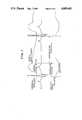
- FIG. 1is a view showing the relationship of aortic blood pressure, ECG and balloon state
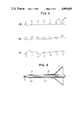
- FIG. 2is a partial sectional view of the vicinity of a human heart and shows electrodes disposed in the patient's aorta;
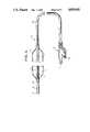
- FIG. 4is a sectional view illustrating an embodiment of an intra-aortic balloon apparatus according to the present invention.
- FIG. 5is a sectional view illustrating another embodiment of an intra-aortic balloon apparatus according to the present invention.
- FIG. 6is a partial sectional view illustrating a third embodiment of an intra-aortic balloon apparatus according to the present invention.
- FIG. 7is a flow chart illustrating the steps of the method of the present invention.
- FIGS. 1, 2 and 3are useful in understanding the principle of the invention.
- FIG. 1shows how aortic blood pressure, ECG and balloon state are related, that the R-wave of the ECG occurs after the P-wave.
- the R-wavegives advance notice of the opening of the aortic valve, and the dicrotic notch appears in the aortic pressure at closure of the aortic valve.
- the balloonfollowing its insertion into the aorta, is deflated in response to the R-wave and inflated after the occurrence of the dicrotic notch. It is thus necessary to accurately predict when the R-wave will occur and to deflate the balloon in synchronism with the R-wave.
- the inventorshave taken note of the significance of the P-wave, which precedes the occurrence of the R-wave, and has considered predicting the occurrence of the R-wave by first accurately sensing the P-wave.
- the P-wavehas but a very small peak in conventional ECG measurement, difficulty is experienced in discriminating between the P-wave and noise. Verification of a distinct P-wave is particularly difficult to achieve in emergency cases where rapid treatment of a patient is required.
- FIG. 2shows an electrode pair placed in a patient's aorta in the vicinity of the heart.
- Numeral 1denotes the ventricle, 2 the atrium, 3 the subclavian arteries, and 4 the aorta.
- An electrode pair 5'is introduced into the aorta through the femoral artery 6 by percutaneous or surgical means. With the electrodes 5 and 5' located at position A in FIG. 2, a R-wave having a high peak is sensed, but the P-wave is small difficult to verify,. as shown in line (a) of FIG. 3. Moving the electrodes 5 and 5' to the B position in FIG. 2 results in detection of the P- an R-waves as waveforms of substantially the same size, as shown in line (b) of FIG.
- the electrodes 5, 5'are introduced into the aorta 4, and obtained by them the electrocardiogram is monitored.
- the electrodes 5, 5'are advanced further into the aorta 4 if the waveform produced is as shown in line (a) of FIG. 3, and are withdrawn an appropriate amount if the waveform obtained is as shown in line (c) of FIG.
- the objectbeing to eventually dispose the electrodes 5, 5' and the balloon 7 at an optimum intra-aortic position, namely position B, such that the tip of balloon pump lies within 2 cm of the origin of the left subclavian artery.
- the P-wavecan be sensed in an accurate fashion, thereby enabling the occurrence of the R-wave to be predicated so that the balloon may be deflated in synchronism the R-wave.
- the method of the present inventionis illustrated in the flowchart of FIG. 7 showing steps 100-108.
- a pressure transducer 8is arranged near the pair of electrodes 5,5' for sensing the aortic blood pressure which enables detection of the dicrotic notch (see FIG. 1), so that the balloon 7 may be inflated in dependence upon the occurrence of the dicrotic notch.
- Inflation and deflation of the balloon 7may be controlled by various computerized means.
- One exampleis to feed the P- and R-wave signals into a computer, which would be programmed to control a gas feed mechanism so as to discharge helium gas from the interior of the balloon 7 in synchronism with the R-wave to deflate the balloon, feed helium gas into the balloon 7 after a prescribed period of time to inflate the balloon, and then discharge the gas in response to the next R-wave signal.
- the computerwould repeat these steps in the manner described.
- Another exampleis to feed the P- and R-waves and a signal indicative of the dicrotic notch into a computer, which would be programmed to control a gas feed mechanism so as to discharge the gas from the balloon 7 in synchronism with the R-wave and feed gas into the balloon 7 in synchronism with the occurrence of the dicrotic notch.
- FIG. 4An embodiment of a intra-aortic balloon apparatus practicing the foregoing method of the present invention is indicated generally at numeral 9 in FIG. 4.
- the balloon 7is provided with a soft and flexible, slender tube-like catheter 10 that passes through the interior of the balloon 7, the distal end of the catheter 10 extending beyond the distal end of the balloon 7,
- the catheter 10has a proximate end to which is secured a coupling 13 having a gas supply port 11 and electric terminals 12.
- the catheter 10defines an internal passageway and its wall is perforated with a plurality of small holes 14 at the portion thereof to which the balloon 7 is attached.
- the gas supply port 11 and the interior of the balloonare thus communicating via the small holes 14 and the passageway inside the catheter 10.
- the balloon 7is inflated and deflated by controlling the inflow and outflow of gas to and from the gas supply port 11.
- the electrode pair 5,5' disposedare at the distal end of the catheter 10 protruding from the distal end of balloon 7.
- the pressure transducer 8is disposed between the electrodes 5,5' which are spaced apart by about 2 cm. Lead wires connected at their one ends to the electrodes 5', 5" and to the pressure transducer 8 are wound in helical form along the inner wall surface of the catheter 10 and extend into the coupling 13 where they are connected at their other ends to the terminals 12.
- the intra-aortic balloon apparatus 9having the foregoing construction is inserted into the aorta through the femoral artery by surgical introduction and senses the P- and R-waves via the electrodes 5, 5' or 5".
- the apparatusis disposed at an intra-aortic position at which the sensed P- and R-waves will be of approximately the same magnitude, as described earlier.
- withdrawal of the gas from the balloon 7is synchronized to the R-wave signal from the electrodes 5, 5' and feed of gas to the balloon 7 is synchronized with the dicrotic notch signal from the pressure transducer 8.
- the apparatusshown generally at numeral 9', includes a tubular first catheter 15 having a proximate end joined to a Y-shaped connector 16 and a distal end supporting a proximate end of the balloon 7 air-tightly.
- a central tubular member 17extends through the interior of the first catheter 15 and has a distal end of comparatively larger diameter projecting from the distal end of first catheter 15 and air-tightly supporting the distal end of the balloon 7.
- the central tubular member 17has a proximate end fixedly secured to a rotary member 18 baving a portion in threaded engagement with the connector 16.
- the connector 16has a port 19 from which a fluid such as helium gas is introduced from an external source, not shown.
- the gasis fed from connector 16 into the balloon 7 through a passageway defined between the inner surface of first catheter 15 and the outer surface of tubular member 17, whereby the balloon 7 is made to inflate. Withdrawing the gas from the balloon through the same passageway causes the balloon to deflate.
- a tubular second catheter 20, the diameter whereof is smaller than that of the first catheter 15,is capable of being passed through the passageway of the central tubular member 17 and has a distal end that projects from the distal end of the tubular member 17.
- the second catheter 20has a proximate end secured to a second connector 21.
- the second connector 21has a tapered distal end portion 22 lockably fitted into a tapered bore formed inside the rotary member 18.
- a knob 23is provided for releasably locking the second connector 21 to the rotary member 18.
- the electrode pair 5, 5' and pressure transducer 8are disposed at the distal end portIon of the second catheter 20.
- the lead wires from the electrodes 5, 5' and transducer 8are wound in helical fashion along inner wall surface of the second catheter 20 and are connected to terminals in the second connector 21.
- the second connector 21is in turn connected to arithmetic circuitry, not shown, the function whereof is described hereinbelow.
- a guide wireis inserted into the aorta from the patient's femoral region as by the Seldinger method and is passed along the aorta until the leading end of the guide wire reaches the vicinity of the patient's heart.
- the other end of the guide wireis inserted into the passageway of tubular member 17, into which the second catheter 20 has not yet been introduced.
- the tubular member 17, with the balloon 7 wrapped around it,is then introduced together with the first catheter 15 into the aorta while being guided along the guide wire. When these have reached a predetermined position inside the aorta, the guide wire is withdrawn from the patient's body through the passageway in tubular member 17.
- the aforementioned arithmetic circuitreceives the P- and R-wave signals from the electrodes 5, 5' and the aortic pressure signal from the pressure transducer 8 to calculate the counterpulsation timing in accordance with these signals.
- the balloon 7is caused to inflate and deflate at the timing calculated.
- the distal end of the tubular member, indicated at numeral 17'is extended beyond the distal end of balloon 7, and the electrodes 5, 5' are disposed on the extended portion of the tubular member 17'.
- the pressure transducer 8, on the other hand,is attached to the distal end of the second catheter, here shown at numeral 20'.
- the second catheter 20'need not be used if measurement of aortic blood pressure is unnecessary.
- the electrodes 5sense the P- and R-waves and the balloon 7 is disposed at the correct intra-aortic position, deflated in response to the R-wave and inflated upon passage of a prescribed period of time.
- the lead wires from the electrodes 5, 5'are imbedded in the wall of the tubular member 17' and may be connected to the Y-shaped first connector 16 (FIG. 5) so that the signals from the electrodes 5, 5' may be extracted from the connector 16.
- a plug(not shown) is fitted into the rotary member 18 in place of the connector 21.
- the present inventionmakes it possible for the balloon to be inflated and deflated in correct response to the actions of the patient's heart, and that the invention enables the balloon-to be disposed at the proper intra-aortic position with greater precision.
Landscapes
- Health & Medical Sciences (AREA)
- Life Sciences & Earth Sciences (AREA)
- Engineering & Computer Science (AREA)
- Heart & Thoracic Surgery (AREA)
- Cardiology (AREA)
- General Health & Medical Sciences (AREA)
- Veterinary Medicine (AREA)
- Biomedical Technology (AREA)
- Public Health (AREA)
- Animal Behavior & Ethology (AREA)
- Anesthesiology (AREA)
- Hematology (AREA)
- Mechanical Engineering (AREA)
- Medical Informatics (AREA)
- Vascular Medicine (AREA)
- Physics & Mathematics (AREA)
- Biophysics (AREA)
- Pathology (AREA)
- Molecular Biology (AREA)
- Surgery (AREA)
- Transplantation (AREA)
- Physiology (AREA)
- Media Introduction/Drainage Providing Device (AREA)
Abstract
Description
This is a division of application Ser. No. 845,557, filed Mar. 28, 1986.
This invention relates to a method of accurately sensing diastolic and systolic motion of a heart, an intra-aortic balloon apparatus for inflating and deflating a balloon introduced into the aorta in the vicinity of the heart, and a method of disposing the balloon apparatus at the proper intra-aortic position.
It is well-known in the art, as described in, for example, the specification of U.S. Pat. No. 4,362,150, to provide cardiac assistance by introducing a balloon into the thoracic aorta of a patient and causing the balloon to inflate and deflate in accordance with the motion of the patient's heart. A balloon of this type is made to inflate during diastole and deflate during systole. This reduces the load on the left ventricle and raises aortic pressure to increase the blood flow to the coronary and carotid arteries. It is therefore essential that cardiac motion be sensed accurately to enable the balloon to be inflated and deflated correctly in accordance with the cardiac cycle.
Methods of sensing cardiac motion include measurement of aortic pressure and measurement based on an electrocardiographic signal. It has been attempted to combine means for effecting such measurements with the aforementioned intra-aortic balloon apparatus. One example in which an intra-aortic balloon is manipulated while aortic pressure is measured is disclosed in the specification of U.S. Pat. No. 4,077,394, which teaches to inflate the balloon for a prescribed period of time that begins at the occurrence of the dicrotic notch. However, since the disclosed method requires that the aortic blood be withdrawn from the patient through a central tube that passes through the balloon in order that the pressure of the blood may be measured extracorporeally, there is a time delay between actual motion of the patient's heart and a measured value showing the actual motion thereof. Moreover, though the balloon is inflated at the dicrotic notch, the occurrence of the dicrotic notch must first be verified. Owing to the time delay, however, verification of the dicrotic notch lags behinds actual occurrence, with the result that there is a tendency for the balloon to be inflated later than actually required. Additionally, the measured pressure is distorted due to the presence of the long tube, and has motion artifact added to it. both of which made consistent detection of the dicrotic notch difficult. A method of inflating and deflating the balloon based on an ECG signal is set forth in the specification of U.S. Pat. No. 707,960. Here two electrodes are arranged at either end of the balloon, the electrodes sense the ECG signal, and the balloon is inflated and deflated in dependence upon a R-wave contained in the signal. The problem with this method is that in some patients the balloon should be deflated prior to the detection of the R-wave thus necessitating prediction of its occurence.
Other shortcoming common to the prior art include problems in correctly disposing the balloon within the thoracic aorta.
Accordingly, an object of the present invention is to solve the aforementioned problems encountered in the prior art.
Another object of the present invention is to provide a novel method of accurately sensing P- and R-waves of an ECG signal.
Still another object of the present invention is to provide a method of accurately placing an intra-aortic balloon in an aorta while sensing P- and R-waves of in ECG signal.
Other features and advantages of the present invention will be apparent from the following description taken in conjunction with the accompanying drawings, in which like reference characters designate the same or similar parts throughout the figures thereof.
FIG. 1 is a view showing the relationship of aortic blood pressure, ECG and balloon state;
FIG. 2 is a partial sectional view of the vicinity of a human heart and shows electrodes disposed in the patient's aorta;
FIG. 3 illustrates three separate waveform diagrams (a), (b), an (c) showing P- and R-waves, the states of which depend upon the position of the electrodes in the aorta;
FIG. 4 is a sectional view illustrating an embodiment of an intra-aortic balloon apparatus according to the present invention;
FIG. 5 is a sectional view illustrating another embodiment of an intra-aortic balloon apparatus according to the present invention;
FIG. 6 is a partial sectional view illustrating a third embodiment of an intra-aortic balloon apparatus according to the present invention; and
FIG. 7 is a flow chart illustrating the steps of the method of the present invention.
Before describing the present invention in detail, reference will be made to FIGS. 1, 2 and 3, which are useful in understanding the principle of the invention.
It is evident from FIG. 1, which shows how aortic blood pressure, ECG and balloon state are related, that the R-wave of the ECG occurs after the P-wave. The R-wave gives advance notice of the opening of the aortic valve, and the dicrotic notch appears in the aortic pressure at closure of the aortic valve. Accordingly, the balloon, following its insertion into the aorta, is deflated in response to the R-wave and inflated after the occurrence of the dicrotic notch. It is thus necessary to accurately predict when the R-wave will occur and to deflate the balloon in synchronism with the R-wave. To this end, the inventors have taken note of the significance of the P-wave, which precedes the occurrence of the R-wave, and has considered predicting the occurrence of the R-wave by first accurately sensing the P-wave. However, since the P-wave has but a very small peak in conventional ECG measurement, difficulty is experienced in discriminating between the P-wave and noise. Verification of a distinct P-wave is particularly difficult to achieve in emergency cases where rapid treatment of a patient is required.
FIG. 2 shows an electrode pair placed in a patient's aorta in the vicinity of the heart. Numeral 1 denotes the ventricle, 2 the atrium, 3 the subclavian arteries, and 4 the aorta. An electrode pair 5' is introduced into the aorta through thefemoral artery 6 by percutaneous or surgical means. With theelectrodes 5 and 5' located at position A in FIG. 2, a R-wave having a high peak is sensed, but the P-wave is small difficult to verify,. as shown in line (a) of FIG. 3. Moving theelectrodes 5 and 5' to the B position in FIG. 2 results in detection of the P- an R-waves as waveforms of substantially the same size, as shown in line (b) of FIG. 3. When theelectrodes 5 and 5' are inserted further toward the C position in FIG. 2, first the P- and the R-waves undergo a polarity inversion, as depicted in line (c) of FIG. 3. Therefore, in accordance with the present invention, theelectrodes 5, 5' are introduced into theaorta 4, and obtained by them the electrocardiogram is monitored. Theelectrodes 5, 5' are advanced further into theaorta 4 if the waveform produced is as shown in line (a) of FIG. 3, and are withdrawn an appropriate amount if the waveform obtained is as shown in line (c) of FIG. 3, with the object being to eventually dispose theelectrodes 5, 5' and theballoon 7 at an optimum intra-aortic position, namely position B, such that the tip of balloon pump lies within 2 cm of the origin of the left subclavian artery. As a re-sult, the P-wave can be sensed in an accurate fashion, thereby enabling the occurrence of the R-wave to be predicated so that the balloon may be deflated in synchronism the R-wave. The method of the present invention is illustrated in the flowchart of FIG. 7 showing steps 100-108.
Apressure transducer 8 is arranged near the pair ofelectrodes 5,5' for sensing the aortic blood pressure which enables detection of the dicrotic notch (see FIG. 1), so that theballoon 7 may be inflated in dependence upon the occurrence of the dicrotic notch.
Inflation and deflation of theballoon 7 may be controlled by various computerized means. One example is to feed the P- and R-wave signals into a computer, which would be programmed to control a gas feed mechanism so as to discharge helium gas from the interior of theballoon 7 in synchronism with the R-wave to deflate the balloon, feed helium gas into theballoon 7 after a prescribed period of time to inflate the balloon, and then discharge the gas in response to the next R-wave signal. The computer would repeat these steps in the manner described. Another example is to feed the P- and R-waves and a signal indicative of the dicrotic notch into a computer, which would be programmed to control a gas feed mechanism so as to discharge the gas from theballoon 7 in synchronism with the R-wave and feed gas into theballoon 7 in synchronism with the occurrence of the dicrotic notch.
An embodiment of a intra-aortic balloon apparatus practicing the foregoing method of the present invention is indicated generally at numeral 9 in FIG. 4. Theballoon 7 is provided with a soft and flexible, slender tube-like catheter 10 that passes through the interior of theballoon 7, the distal end of the catheter 10 extending beyond the distal end of theballoon 7, The catheter 10 has a proximate end to which is secured a coupling 13 having agas supply port 11 andelectric terminals 12. The catheter 10 defines an internal passageway and its wall is perforated with a plurality ofsmall holes 14 at the portion thereof to which theballoon 7 is attached. Thegas supply port 11 and the interior of the balloon are thus communicating via thesmall holes 14 and the passageway inside the catheter 10. Theballoon 7 is inflated and deflated by controlling the inflow and outflow of gas to and from thegas supply port 11.
Theelectrode pair 5,5' disposed are at the distal end of the catheter 10 protruding from the distal end ofballoon 7. Thepressure transducer 8 is disposed between theelectrodes 5,5' which are spaced apart by about 2 cm. Lead wires connected at their one ends to theelectrodes 5', 5" and to thepressure transducer 8 are wound in helical form along the inner wall surface of the catheter 10 and extend into the coupling 13 where they are connected at their other ends to theterminals 12.
The intra-aortic balloon apparatus 9 having the foregoing construction is inserted into the aorta through the femoral artery by surgical introduction and senses the P- and R-waves via theelectrodes balloon 7 is synchronized to the R-wave signal from theelectrodes 5, 5' and feed of gas to theballoon 7 is synchronized with the dicrotic notch signal from thepressure transducer 8.
Another embodiment of an intra-aortic balloon apparatus according to the present invention will now be described with reference to FIG. 5. The apparatus, shown generally at numeral 9', includes a tubularfirst catheter 15 having a proximate end joined to a Y-shapedconnector 16 and a distal end supporting a proximate end of theballoon 7 air-tightly. Acentral tubular member 17 extends through the interior of thefirst catheter 15 and has a distal end of comparatively larger diameter projecting from the distal end offirst catheter 15 and air-tightly supporting the distal end of theballoon 7. Thecentral tubular member 17 has a proximate end fixedly secured to arotary member 18 baving a portion in threaded engagement with theconnector 16. Turning therotary member 18 with respect to theconnector 16 rotates thetubular member 17 so that theballoon 7 may be wrapped around thetubular member 17 by rotating the same in one direction and unwrapped from thetubular member 17 by rotating same in the opposite direction. Theconnector 16 has aport 19 from which a fluid such as helium gas is introduced from an external source, not shown. The gas is fed fromconnector 16 into theballoon 7 through a passageway defined between the inner surface offirst catheter 15 and the outer surface oftubular member 17, whereby theballoon 7 is made to inflate. Withdrawing the gas from the balloon through the same passageway causes the balloon to deflate.
A tubularsecond catheter 20, the diameter whereof is smaller than that of thefirst catheter 15, is capable of being passed through the passageway of thecentral tubular member 17 and has a distal end that projects from the distal end of thetubular member 17. Thesecond catheter 20 has a proximate end secured to a second connector 21. The second connector 21 has a tapereddistal end portion 22 lockably fitted into a tapered bore formed inside therotary member 18. Aknob 23 is provided for releasably locking the second connector 21 to therotary member 18.
Theelectrode pair 5, 5' andpressure transducer 8 are disposed at the distal end portIon of thesecond catheter 20. The lead wires from theelectrodes 5, 5' andtransducer 8 are wound in helical fashion along inner wall surface of thesecond catheter 20 and are connected to terminals in the second connector 21. The second connector 21 is in turn connected to arithmetic circuitry, not shown, the function whereof is described hereinbelow.
To use the intra-aortic balloon apparatus 9' shown in FIG. 5, a guide wire, not shown, is inserted into the aorta from the patient's femoral region as by the Seldinger method and is passed along the aorta until the leading end of the guide wire reaches the vicinity of the patient's heart. Next, the other end of the guide wire is inserted into the passageway oftubular member 17, into which thesecond catheter 20 has not yet been introduced. Thetubular member 17, with theballoon 7 wrapped around it, is then introduced together with thefirst catheter 15 into the aorta while being guided along the guide wire. When these have reached a predetermined position inside the aorta, the guide wire is withdrawn from the patient's body through the passageway intubular member 17. This is followed by inserting the distal end of thesecond catheter 20 into thetubular member 17 and then introducing the distal end of thesecond catheter 20 into the aorta through thetubular member 17 while manipulating the connector 21 to which thesecond catheter 20 is affixed. The tapereddistal end portion 22 of second connector 21 is brought into abutting contact with therotary member 18 and theknob 23 is turned to lock the second connector 21 androtary member 18 together. The connector 21 is connected to the aforementioned arithmetic circuit, not shown, and theelectrodes 5, 5' at the distal end of thesecond catheter 20 sense the P- and R-waves. The resulting signals are monitored so that theballoon 7 may be moved to the correct intra-aortic position by manipulating the connector 21. Thus, theballoon 7 has thus been moved to the correct position.
The aforementioned arithmetic circuit receives the P- and R-wave signals from theelectrodes 5, 5' and the aortic pressure signal from thepressure transducer 8 to calculate the counterpulsation timing in accordance with these signals. Theballoon 7 is caused to inflate and deflate at the timing calculated.
In an embodiment of the intra-aortic balloon apparatus shown in FIG. 6, the distal end of the tubular member, indicated at numeral 17', is extended beyond the distal end ofballoon 7, and theelectrodes 5, 5' are disposed on the extended portion of the tubular member 17'. Thepressure transducer 8, on the other hand, is attached to the distal end of the second catheter, here shown at numeral 20'. With this arrangement, the second catheter 20' need not be used if measurement of aortic blood pressure is unnecessary. In such case, theelectrodes 5 sense the P- and R-waves and theballoon 7 is disposed at the correct intra-aortic position, deflated in response to the R-wave and inflated upon passage of a prescribed period of time. Note that the lead wires from theelectrodes 5, 5' are imbedded in the wall of the tubular member 17' and may be connected to the Y-shaped first connector 16 (FIG. 5) so that the signals from theelectrodes 5, 5' may be extracted from theconnector 16. When the second catheter 20' is not used, a plug (not shown) is fitted into therotary member 18 in place of the connector 21.
It will be evident from the foregoing description that the present invention makes it possible for the balloon to be inflated and deflated in correct response to the actions of the patient's heart, and that the invention enables the balloon-to be disposed at the proper intra-aortic position with greater precision.
As many apparently widely different embodiments of the present invention can be made without departing from the spirit and scope thereof, it is to be understood that the invention is not limited to the specific embodiments thereof except as definded in the appended claims.
Claims (2)
1. An electrocardiographic measurement method for assistance in controlling deflation of an intra-aortic balloon pump disposed in the thoracic aorta of a patient, comprising the steps of:
disposing at least a pair of spaced electrodes inside the thoracic aorta near the patient's heart;
sensing R-waves and P-waves by said electrodes;
moving said electrodes to a position in the thoracic aorta where the R- and P-waves are substantially equal in magnitude for accurately detecting the occurrence of the P-wave;
predicting subsequent occurrences of the R-waves in accordance with the detected occurrences of the P-waves; and
initiating deflation of the intra-aortic balloon pump in accordance with the predicted subsequent occurrences of the R-waves such that the balloon pump is deflated synchronously with each R-wave occurrence.
2. The electrocardiographic method according to claim 1, wherein the step of moving said electrodes include the substeps of:
inserting the electrodes into a deeper region in the thoracic aorta when the R-wave is larger than the P-wave at a first present position in the thoracic aorta;
withdrawing the electrodes into a shallower region in the thoracic aorta when the R-wave and P-wave change polarity at a second present position in the thoracic aorta; and
determining a position intermediate said first and second present positions in the thoracic aorta at which the R- and P-waves are substantially equal in magnitude.
Priority Applications (1)
| Application Number | Priority Date | Filing Date | Title |
|---|---|---|---|
| US07/031,137US4809681A (en) | 1986-03-28 | 1987-03-30 | Electrocardiographic measurement method for controlling an intra-aortic balloon pump |
Applications Claiming Priority (2)
| Application Number | Priority Date | Filing Date | Title |
|---|---|---|---|
| US06/845,557US4692148A (en) | 1986-03-28 | 1986-03-28 | Intra-aortic balloon pump apparatus and method of using same |
| US07/031,137US4809681A (en) | 1986-03-28 | 1987-03-30 | Electrocardiographic measurement method for controlling an intra-aortic balloon pump |
Related Parent Applications (1)
| Application Number | Title | Priority Date | Filing Date |
|---|---|---|---|
| US06/845,557DivisionUS4692148A (en) | 1986-03-28 | 1986-03-28 | Intra-aortic balloon pump apparatus and method of using same |
Publications (1)
| Publication Number | Publication Date |
|---|---|
| US4809681Atrue US4809681A (en) | 1989-03-07 |
Family
ID=26706881
Family Applications (1)
| Application Number | Title | Priority Date | Filing Date |
|---|---|---|---|
| US07/031,137Expired - LifetimeUS4809681A (en) | 1986-03-28 | 1987-03-30 | Electrocardiographic measurement method for controlling an intra-aortic balloon pump |
Country Status (1)
| Country | Link |
|---|---|
| US (1) | US4809681A (en) |
Cited By (86)
| Publication number | Priority date | Publication date | Assignee | Title |
|---|---|---|---|---|
| WO1990013322A1 (en)* | 1989-05-05 | 1990-11-15 | Jacob Segalowitz | Heart-assist balloon pump |
| US5158529A (en)* | 1990-03-29 | 1992-10-27 | Aisin Seiki Kabushiki Kaisha | Pumping device for operating an intra-aortic balloon |
| US5169379A (en)* | 1989-06-14 | 1992-12-08 | L-Vad Technology | In-series ventricular assist system and method of controlling same |
| US5494032A (en)* | 1991-07-12 | 1996-02-27 | Sandia Corporation | Oximeter for reliable clinical determination of blood oxygen saturation in a fetus |
| WO1996034531A1 (en) | 1995-05-05 | 1996-11-07 | G. Van Wijnsberghe En Co. N.V. | Method of delivering animals to a processing area and an apparatus therefor |
| US5755687A (en) | 1997-04-01 | 1998-05-26 | Heartport, Inc. | Methods and devices for occluding a patient's ascending aorta |
| US5765568A (en) | 1994-05-27 | 1998-06-16 | Heartport, Inc. | Catheter system and method for venting the left ventricle |
| US5769812A (en) | 1991-07-16 | 1998-06-23 | Heartport, Inc. | System for cardiac procedures |
| US5792094A (en) | 1991-07-16 | 1998-08-11 | Heartport, Inc. | Method of delivering cardioplegic fluid to a patient's heart |
| US5904666A (en)* | 1997-08-18 | 1999-05-18 | L.Vad Technology, Inc. | Method and apparatus for measuring flow rate and controlling delivered volume of fluid through a valve aperture |
| US5935103A (en)* | 1991-12-17 | 1999-08-10 | Heartport, Inc. | Blood vessel occlusion device |
| US6042532A (en)* | 1998-03-09 | 2000-03-28 | L. Vad Technology, Inc. | Pressure control system for cardiac assist device |
| US6066086A (en)* | 1996-11-01 | 2000-05-23 | Nimbus, Inc. | Speed control system for implanted blood pumps |
| US6132363A (en)* | 1997-09-30 | 2000-10-17 | L.Vad Technology, Inc. | Cardiovascular support control system |
| US6159178A (en) | 1998-01-23 | 2000-12-12 | Heartport, Inc. | Methods and devices for occluding the ascending aorta and maintaining circulation of oxygenated blood in the patient when the patient's heart is arrested |
| NL1016320C2 (en) | 2000-10-03 | 2002-04-04 | Jozef Reinier Cornelis Jansen | Device for controlling heart supporting devices. |
| US6482171B1 (en) | 1991-07-16 | 2002-11-19 | Heartport, Inc. | Multi-lumen catheter |
| US6511412B1 (en) | 1998-09-30 | 2003-01-28 | L. Vad Technology, Inc. | Cardivascular support control system |
| WO2003082379A1 (en)* | 2002-03-26 | 2003-10-09 | Frazier Howard O | Temporary heart-assist system |
| US6679829B2 (en) | 1999-05-20 | 2004-01-20 | Paul Nigroni | Intra-aortic balloon pump having improved automated electrocardiogram based intra-aortic balloon deflation timing |
| US20040039288A1 (en)* | 1995-12-22 | 2004-02-26 | Hoeksel Sebastiaan Adrianus Alphonsus Petrus | Device for determining a characteristic point in the cardiac cycle |
| US6735532B2 (en) | 1998-09-30 | 2004-05-11 | L. Vad Technology, Inc. | Cardiovascular support control system |
| US20040152945A1 (en)* | 2003-01-31 | 2004-08-05 | Adrian Kantrowitz | Stable aortic blood pump implant |
| EP1058512A4 (en)* | 1997-05-15 | 2005-03-16 | Lvad Technology Inc | External blood pressure sensor apparatus and method |
| US20050148812A1 (en)* | 2003-08-29 | 2005-07-07 | Datascope Investment Corp. | Timing of intra-aortic balloon pump therapy |
| US20060030747A1 (en)* | 2004-07-09 | 2006-02-09 | Kantrowitz Allen B | Synchronization system between aortic valve and cardiac assist device |
| US20070156009A1 (en)* | 2006-01-05 | 2007-07-05 | Patricia Hanlon-Pena | Methods and apparatus for selecting intra-aortic balloon deflation timing |
| US20070161916A1 (en)* | 2006-01-12 | 2007-07-12 | Zantos George N | Adaptive real time ECG triggering and uses thereof |
| US7468050B1 (en) | 2002-12-27 | 2008-12-23 | L. Vad Technology, Inc. | Long term ambulatory intra-aortic balloon pump |
| US20090198308A1 (en)* | 2008-01-31 | 2009-08-06 | Enopace Biomedical Ltd. | Intra-aortic electrical counterpulsation |
| US20100036227A1 (en)* | 2007-11-26 | 2010-02-11 | C. R. Bard, Inc. | Apparatus and display methods relating to intravascular placement of a catheter |
| US20100094116A1 (en)* | 2008-10-07 | 2010-04-15 | Lucent Medical Systems, Inc. | Percutaneous magnetic gastrostomy |
| US20100204569A1 (en)* | 2007-11-26 | 2010-08-12 | C. R. Bard, Inc. | System for placement of a catheter including a signal-generating stylet |
| US20100305392A1 (en)* | 2008-01-31 | 2010-12-02 | Enopace Biomedical Ltd. | Thoracic aorta and vagus nerve stimulation |
| US20100318026A1 (en)* | 2009-06-12 | 2010-12-16 | Romedex International Srl | Devices and Methods for Endovascular Electrography |
| US20100331712A1 (en)* | 2006-10-23 | 2010-12-30 | Bard Access Systems, Inc. | Method of locating the tip of a central venous catheter |
| US20110015533A1 (en)* | 2007-11-26 | 2011-01-20 | C.R. Bard, Inc. | Stylets for use with apparatus for intravascular placement of a catheter |
| US20110196248A1 (en)* | 2009-06-12 | 2011-08-11 | Bard Access Systems, Inc. | Apparatus and method for catheter navigation and tip location |
| US8388541B2 (en) | 2007-11-26 | 2013-03-05 | C. R. Bard, Inc. | Integrated system for intravascular placement of a catheter |
| US8388546B2 (en) | 2006-10-23 | 2013-03-05 | Bard Access Systems, Inc. | Method of locating the tip of a central venous catheter |
| US8478382B2 (en) | 2008-02-11 | 2013-07-02 | C. R. Bard, Inc. | Systems and methods for positioning a catheter |
| USD699359S1 (en) | 2011-08-09 | 2014-02-11 | C. R. Bard, Inc. | Ultrasound probe head |
| US20140142590A1 (en)* | 2012-11-20 | 2014-05-22 | NeuroTronik IP Holding (Jersey) Limited | Positioning Methods for Intravascular Electrode Arrays for Neuromodulation |
| US8784336B2 (en) | 2005-08-24 | 2014-07-22 | C. R. Bard, Inc. | Stylet apparatuses and methods of manufacture |
| US8801693B2 (en) | 2010-10-29 | 2014-08-12 | C. R. Bard, Inc. | Bioimpedance-assisted placement of a medical device |
| US8855783B2 (en) | 2011-09-09 | 2014-10-07 | Enopace Biomedical Ltd. | Detector-based arterial stimulation |
| US8862243B2 (en) | 2005-07-25 | 2014-10-14 | Rainbow Medical Ltd. | Electrical stimulation of blood vessels |
| USD724745S1 (en) | 2011-08-09 | 2015-03-17 | C. R. Bard, Inc. | Cap for an ultrasound probe |
| US9198600B2 (en) | 2005-05-06 | 2015-12-01 | Vasonova, Inc. | Endovascular access and guidance system utilizing divergent beam ultrasound |
| US9211107B2 (en) | 2011-11-07 | 2015-12-15 | C. R. Bard, Inc. | Ruggedized ultrasound hydrogel insert |
| US9339206B2 (en) | 2009-06-12 | 2016-05-17 | Bard Access Systems, Inc. | Adaptor for endovascular electrocardiography |
| US9456766B2 (en) | 2007-11-26 | 2016-10-04 | C. R. Bard, Inc. | Apparatus for use with needle insertion guidance system |
| US9492097B2 (en) | 2007-11-26 | 2016-11-15 | C. R. Bard, Inc. | Needle length determination and calibration for insertion guidance system |
| US9521961B2 (en) | 2007-11-26 | 2016-12-20 | C. R. Bard, Inc. | Systems and methods for guiding a medical instrument |
| US9526637B2 (en) | 2011-09-09 | 2016-12-27 | Enopace Biomedical Ltd. | Wireless endovascular stent-based electrodes |
| US9532724B2 (en) | 2009-06-12 | 2017-01-03 | Bard Access Systems, Inc. | Apparatus and method for catheter navigation using endovascular energy mapping |
| US9554716B2 (en) | 2007-11-26 | 2017-01-31 | C. R. Bard, Inc. | Insertion guidance system for needles and medical components |
| US20170035392A1 (en)* | 2005-05-06 | 2017-02-09 | Vasonova, Inc. | Apparatus and method for endovascular device guiding and positioning using physiological parameters |
| US9649048B2 (en) | 2007-11-26 | 2017-05-16 | C. R. Bard, Inc. | Systems and methods for breaching a sterile field for intravascular placement of a catheter |
| US9649487B2 (en) | 2010-08-05 | 2017-05-16 | Enopace Biomedical Ltd. | Enhancing perfusion by contraction |
| US9694122B2 (en)* | 2003-01-31 | 2017-07-04 | L-Vad Technology, Inc. | Rigid body aortic blood pump implant |
| US9789236B2 (en) | 2013-03-14 | 2017-10-17 | Yale University | Implantable heart pump controller |
| US9839372B2 (en) | 2014-02-06 | 2017-12-12 | C. R. Bard, Inc. | Systems and methods for guidance and placement of an intravascular device |
| US9901714B2 (en) | 2008-08-22 | 2018-02-27 | C. R. Bard, Inc. | Catheter assembly including ECG sensor and magnetic assemblies |
| US9919088B2 (en) | 2013-03-14 | 2018-03-20 | Yale University | Implantable heart pump controller |
| US10046139B2 (en) | 2010-08-20 | 2018-08-14 | C. R. Bard, Inc. | Reconfirmation of ECG-assisted catheter tip placement |
| US10349890B2 (en) | 2015-06-26 | 2019-07-16 | C. R. Bard, Inc. | Connector interface for ECG-based catheter positioning system |
| US10449330B2 (en) | 2007-11-26 | 2019-10-22 | C. R. Bard, Inc. | Magnetic element-equipped needle assemblies |
| US10524691B2 (en) | 2007-11-26 | 2020-01-07 | C. R. Bard, Inc. | Needle assembly including an aligned magnetic element |
| US10639008B2 (en) | 2009-10-08 | 2020-05-05 | C. R. Bard, Inc. | Support and cover structures for an ultrasound probe head |
| EP3692899A1 (en)* | 2015-12-02 | 2020-08-12 | Neurescue ApS | A device for emergency treatment of cardiac arrest |
| US10751509B2 (en) | 2007-11-26 | 2020-08-25 | C. R. Bard, Inc. | Iconic representations for guidance of an indwelling medical device |
| US10779965B2 (en) | 2013-11-06 | 2020-09-22 | Enopace Biomedical Ltd. | Posts with compliant junctions |
| US10820885B2 (en) | 2012-06-15 | 2020-11-03 | C. R. Bard, Inc. | Apparatus and methods for detection of a removable cap on an ultrasound probe |
| US10973584B2 (en) | 2015-01-19 | 2021-04-13 | Bard Access Systems, Inc. | Device and method for vascular access |
| US10992079B2 (en) | 2018-10-16 | 2021-04-27 | Bard Access Systems, Inc. | Safety-equipped connection systems and methods thereof for establishing electrical connections |
| US11000207B2 (en) | 2016-01-29 | 2021-05-11 | C. R. Bard, Inc. | Multiple coil system for tracking a medical device |
| US11090481B2 (en) | 2012-05-21 | 2021-08-17 | University Of Washington Through Its Center For Commercialization | Wireless power delivery in dynamic environments |
| US11103213B2 (en) | 2009-10-08 | 2021-08-31 | C. R. Bard, Inc. | Spacers for use with an ultrasound probe |
| US20210290934A1 (en)* | 2018-07-17 | 2021-09-23 | Viaderm Llc | Indwelling hyper-dimensional cardiac physiologic data logging and transmission system and method of doing business |
| US11241572B2 (en) | 2018-09-25 | 2022-02-08 | Tc1 Llc | Adaptive speed control algorithms and controllers for optimizing flow in ventricular assist devices |
| US11285313B2 (en) | 2019-05-02 | 2022-03-29 | Nupulsecv, Inc. | Predictive QRS detection and R-to-R timing systems and methods |
| US20220184377A1 (en)* | 2020-12-10 | 2022-06-16 | Abiomed, Inc. | Systems and methods for determining positioning of intracardiac devices |
| US11400299B1 (en) | 2021-09-14 | 2022-08-02 | Rainbow Medical Ltd. | Flexible antenna for stimulator |
| US11565102B2 (en) | 2019-02-01 | 2023-01-31 | Kardiatec SA | Pressure unloading left ventricular assist device and methods for assisting a human heart |
| US11621583B2 (en) | 2012-05-21 | 2023-04-04 | University Of Washington | Distributed control adaptive wireless power transfer system |
Citations (18)
| Publication number | Priority date | Publication date | Assignee | Title |
|---|---|---|---|---|
| US3081765A (en)* | 1960-06-15 | 1963-03-19 | Honeywell Regulator Co | Medical body function recorder |
| US3533403A (en)* | 1967-05-10 | 1970-10-13 | Riley D Woodson | Combination heart catheter and electrode |
| US3553625A (en)* | 1967-12-29 | 1971-01-05 | Statham Instrument Inc | Side sensitive miniaturized pressure transducer |
| US3585983A (en)* | 1968-03-05 | 1971-06-22 | Adrian Kantrowitz | Cardiac assisting pump |
| US3707960A (en)* | 1970-09-03 | 1973-01-02 | Us Health | Balloon cardiac assisting pump having intraaortic electrocardiographic electrodes |
| US3896803A (en)* | 1973-08-20 | 1975-07-29 | Betamite Electronic Devices | Valve controlled single needle blood processing systems |
| US3903897A (en)* | 1972-03-11 | 1975-09-09 | Kent Cambridge Medical Ltd | Cardiac pacer |
| US3913565A (en)* | 1973-05-18 | 1975-10-21 | Olympus Optical Co | Guide tube for a treating instrument to be inserted into body cavity |
| US4077394A (en)* | 1976-08-25 | 1978-03-07 | Mccurdy Martin D | Integral pressure sensor probe for a cardiac assistance device |
| US4148319A (en)* | 1976-12-29 | 1979-04-10 | Kasper Richard F | Urinary retention catheter |
| US4191193A (en)* | 1976-02-29 | 1980-03-04 | Mitsubishi Petrochemical Co. Ltd. | Catheter head-type transducer |
| US4274423A (en)* | 1977-12-15 | 1981-06-23 | Kabushiki Kaisha Toyota Chuo Kenkyusho | Catheter tip pressure transducer |
| US4284073A (en)* | 1977-10-11 | 1981-08-18 | Krause Horst E | Method and apparatus for pumping blood within a vessel |
| US4362150A (en)* | 1980-09-10 | 1982-12-07 | Kontron Cardiovascular Inc. | Percutaneous intra-aortic balloon apparatus |
| SU995751A1 (en)* | 1980-04-10 | 1983-02-15 | Горьковский государственный медицинский институт им.С.М.Кирова | Device for cardiodilation |
| US4552127A (en)* | 1983-04-01 | 1985-11-12 | Peter Schiff | Percutaneous intra-aortic balloon having an EKG electrode and a twisting stylet for coupling the EKG electrode to monitoring and/or pacing instrumentation external to the body |
| US4569332A (en)* | 1983-04-13 | 1986-02-11 | Peter Schiff | Method and apparatus for treating a heart patient through the coordinating efforts of balloon pumping and dispensing catheters |
| US4630597A (en)* | 1984-04-30 | 1986-12-23 | Adrian Kantrowitz | Dynamic aortic patch for thoracic or abdominal implantation |
- 1987
- 1987-03-30USUS07/031,137patent/US4809681A/ennot_activeExpired - Lifetime
Patent Citations (18)
| Publication number | Priority date | Publication date | Assignee | Title |
|---|---|---|---|---|
| US3081765A (en)* | 1960-06-15 | 1963-03-19 | Honeywell Regulator Co | Medical body function recorder |
| US3533403A (en)* | 1967-05-10 | 1970-10-13 | Riley D Woodson | Combination heart catheter and electrode |
| US3553625A (en)* | 1967-12-29 | 1971-01-05 | Statham Instrument Inc | Side sensitive miniaturized pressure transducer |
| US3585983A (en)* | 1968-03-05 | 1971-06-22 | Adrian Kantrowitz | Cardiac assisting pump |
| US3707960A (en)* | 1970-09-03 | 1973-01-02 | Us Health | Balloon cardiac assisting pump having intraaortic electrocardiographic electrodes |
| US3903897A (en)* | 1972-03-11 | 1975-09-09 | Kent Cambridge Medical Ltd | Cardiac pacer |
| US3913565A (en)* | 1973-05-18 | 1975-10-21 | Olympus Optical Co | Guide tube for a treating instrument to be inserted into body cavity |
| US3896803A (en)* | 1973-08-20 | 1975-07-29 | Betamite Electronic Devices | Valve controlled single needle blood processing systems |
| US4191193A (en)* | 1976-02-29 | 1980-03-04 | Mitsubishi Petrochemical Co. Ltd. | Catheter head-type transducer |
| US4077394A (en)* | 1976-08-25 | 1978-03-07 | Mccurdy Martin D | Integral pressure sensor probe for a cardiac assistance device |
| US4148319A (en)* | 1976-12-29 | 1979-04-10 | Kasper Richard F | Urinary retention catheter |
| US4284073A (en)* | 1977-10-11 | 1981-08-18 | Krause Horst E | Method and apparatus for pumping blood within a vessel |
| US4274423A (en)* | 1977-12-15 | 1981-06-23 | Kabushiki Kaisha Toyota Chuo Kenkyusho | Catheter tip pressure transducer |
| SU995751A1 (en)* | 1980-04-10 | 1983-02-15 | Горьковский государственный медицинский институт им.С.М.Кирова | Device for cardiodilation |
| US4362150A (en)* | 1980-09-10 | 1982-12-07 | Kontron Cardiovascular Inc. | Percutaneous intra-aortic balloon apparatus |
| US4552127A (en)* | 1983-04-01 | 1985-11-12 | Peter Schiff | Percutaneous intra-aortic balloon having an EKG electrode and a twisting stylet for coupling the EKG electrode to monitoring and/or pacing instrumentation external to the body |
| US4569332A (en)* | 1983-04-13 | 1986-02-11 | Peter Schiff | Method and apparatus for treating a heart patient through the coordinating efforts of balloon pumping and dispensing catheters |
| US4630597A (en)* | 1984-04-30 | 1986-12-23 | Adrian Kantrowitz | Dynamic aortic patch for thoracic or abdominal implantation |
Non-Patent Citations (2)
| Title |
|---|
| Mansfield Scientific, Inc. brochure directed to Ventri Pace Torque and Ventri Pace Semi Floater catheters.* |
| Mansfield Scientific, Inc. brochure directed to Ventri-Pace Torque and Ventri-Pace Semi-Floater catheters. |
Cited By (173)
| Publication number | Priority date | Publication date | Assignee | Title |
|---|---|---|---|---|
| WO1990013322A1 (en)* | 1989-05-05 | 1990-11-15 | Jacob Segalowitz | Heart-assist balloon pump |
| US5169379A (en)* | 1989-06-14 | 1992-12-08 | L-Vad Technology | In-series ventricular assist system and method of controlling same |
| US5158529A (en)* | 1990-03-29 | 1992-10-27 | Aisin Seiki Kabushiki Kaisha | Pumping device for operating an intra-aortic balloon |
| US5494032A (en)* | 1991-07-12 | 1996-02-27 | Sandia Corporation | Oximeter for reliable clinical determination of blood oxygen saturation in a fetus |
| US6482171B1 (en) | 1991-07-16 | 2002-11-19 | Heartport, Inc. | Multi-lumen catheter |
| US5769812A (en) | 1991-07-16 | 1998-06-23 | Heartport, Inc. | System for cardiac procedures |
| US5792094A (en) | 1991-07-16 | 1998-08-11 | Heartport, Inc. | Method of delivering cardioplegic fluid to a patient's heart |
| US5885238A (en) | 1991-07-16 | 1999-03-23 | Heartport, Inc. | System for cardiac procedures |
| US5935103A (en)* | 1991-12-17 | 1999-08-10 | Heartport, Inc. | Blood vessel occlusion device |
| US6224619B1 (en) | 1991-12-17 | 2001-05-01 | Heartport, Inc. | Blood vessel occlusion trocar having size and shape varying insertion body |
| US5997505A (en)* | 1991-12-17 | 1999-12-07 | Heartport, Inc. | Method of cannulating an ascending aorta using a blood vessel occlusion device |
| US5941894A (en)* | 1991-12-17 | 1999-08-24 | Heartport, Inc. | Blood vessel occlusion device |
| US20020161321A1 (en)* | 1994-05-27 | 2002-10-31 | Sweezer, William P. | Method of occluding a patient's ascending aorta and delivering cardioplegic fluid |
| US5810757A (en) | 1994-05-27 | 1998-09-22 | Heartport, Inc. | Catheter system and method for total isolation of the heart |
| US5800375A (en) | 1994-05-27 | 1998-09-01 | Heartport, Inc. | Catheter system and method for providing cardiopulmonary bypass pump support during heart surgery |
| US5765568A (en) | 1994-05-27 | 1998-06-16 | Heartport, Inc. | Catheter system and method for venting the left ventricle |
| US6398752B1 (en) | 1994-05-27 | 2002-06-04 | William P. Sweezer, Jr. | Method of occluding a patient's ascending aorta and delivery cardioplegic fluid |
| US6248086B1 (en) | 1994-05-27 | 2001-06-19 | Heartport, Inc. | Method for cannulating a patient's aortic arch and occluding the patient's ascending aortic arch |
| US6293920B1 (en) | 1994-05-27 | 2001-09-25 | Heartport, Inc. | Catheter system and method for providing cardiopulmonary bypass pump support during heart surgery |
| WO1996034531A1 (en) | 1995-05-05 | 1996-11-07 | G. Van Wijnsberghe En Co. N.V. | Method of delivering animals to a processing area and an apparatus therefor |
| US6887206B2 (en)* | 1995-12-22 | 2005-05-03 | Arrow International Investment Corp. | Device for determining a characteristic point in the cardiac cycle |
| US20050197584A1 (en)* | 1995-12-22 | 2005-09-08 | Hoeksel Sebastiaan Adrianus A.P. | Device for determining a characteristic point in the cardiac cycle |
| US20040039288A1 (en)* | 1995-12-22 | 2004-02-26 | Hoeksel Sebastiaan Adrianus Alphonsus Petrus | Device for determining a characteristic point in the cardiac cycle |
| US7090644B2 (en) | 1995-12-22 | 2006-08-15 | Arrow International Investment Corp. | Device for determining a characteristic point in the cardiac cycle |
| US6066086A (en)* | 1996-11-01 | 2000-05-23 | Nimbus, Inc. | Speed control system for implanted blood pumps |
| US6423031B1 (en) | 1997-04-01 | 2002-07-23 | Brian S. Donlon | Methods and devices for occluding a patient's ascending aorta |
| US6056723A (en) | 1997-04-01 | 2000-05-02 | Heartport, Inc. | Methods and devices for occluding a patient's ascending aorta |
| US5755687A (en) | 1997-04-01 | 1998-05-26 | Heartport, Inc. | Methods and devices for occluding a patient's ascending aorta |
| EP1058512A4 (en)* | 1997-05-15 | 2005-03-16 | Lvad Technology Inc | External blood pressure sensor apparatus and method |
| US5904666A (en)* | 1997-08-18 | 1999-05-18 | L.Vad Technology, Inc. | Method and apparatus for measuring flow rate and controlling delivered volume of fluid through a valve aperture |
| US6132363A (en)* | 1997-09-30 | 2000-10-17 | L.Vad Technology, Inc. | Cardiovascular support control system |
| US6159178A (en) | 1998-01-23 | 2000-12-12 | Heartport, Inc. | Methods and devices for occluding the ascending aorta and maintaining circulation of oxygenated blood in the patient when the patient's heart is arrested |
| US6589206B1 (en) | 1998-01-23 | 2003-07-08 | Heartport, Inc. | Methods and devices for occluding the ascending aorta and maintaining circulation of oxygenated blood in the patient when the patient's heart is arrested |
| US6902556B2 (en) | 1998-01-23 | 2005-06-07 | Heartport, Inc. | Methods and devices for occluding the ascending aorta and maintaining circulation oxygenated blood in the patient when the patient's heart is arrested |
| US6042532A (en)* | 1998-03-09 | 2000-03-28 | L. Vad Technology, Inc. | Pressure control system for cardiac assist device |
| US6735532B2 (en) | 1998-09-30 | 2004-05-11 | L. Vad Technology, Inc. | Cardiovascular support control system |
| US6511412B1 (en) | 1998-09-30 | 2003-01-28 | L. Vad Technology, Inc. | Cardivascular support control system |
| US6679829B2 (en) | 1999-05-20 | 2004-01-20 | Paul Nigroni | Intra-aortic balloon pump having improved automated electrocardiogram based intra-aortic balloon deflation timing |
| NL1016320C2 (en) | 2000-10-03 | 2002-04-04 | Jozef Reinier Cornelis Jansen | Device for controlling heart supporting devices. |
| US20040059183A1 (en)* | 2000-10-03 | 2004-03-25 | Jansen Jozef Reinier Cornelis | Apparatus for controlling heart assist devices |
| US7169109B2 (en) | 2000-10-03 | 2007-01-30 | Arrow International, Inc. | Methods and apparatus for controlling heart assist devices |
| WO2002028280A1 (en) | 2000-10-03 | 2002-04-11 | Arrow International, Inc. | Apparatus for controlling heart assist devices |
| US6669624B2 (en)* | 2002-03-26 | 2003-12-30 | O. Howard Frazier | Temporary heart-assist system |
| WO2003082379A1 (en)* | 2002-03-26 | 2003-10-09 | Frazier Howard O | Temporary heart-assist system |
| US7468050B1 (en) | 2002-12-27 | 2008-12-23 | L. Vad Technology, Inc. | Long term ambulatory intra-aortic balloon pump |
| US8540618B2 (en) | 2003-01-31 | 2013-09-24 | L-Vad Technology, Inc. | Stable aortic blood pump implant |
| US9433715B2 (en) | 2003-01-31 | 2016-09-06 | L-Vad Technology, Inc. | Stable aortic blood pump implant |
| US9694122B2 (en)* | 2003-01-31 | 2017-07-04 | L-Vad Technology, Inc. | Rigid body aortic blood pump implant |
| US20040152945A1 (en)* | 2003-01-31 | 2004-08-05 | Adrian Kantrowitz | Stable aortic blood pump implant |
| US20050148812A1 (en)* | 2003-08-29 | 2005-07-07 | Datascope Investment Corp. | Timing of intra-aortic balloon pump therapy |
| US7250025B2 (en) | 2003-08-29 | 2007-07-31 | Datascope Investment Corp. | Timing of intra-aortic balloon pump therapy |
| US7513864B2 (en)* | 2004-07-09 | 2009-04-07 | Kantrowitz Allen B | Synchronization system between aortic valve and cardiac assist device |
| US20060030747A1 (en)* | 2004-07-09 | 2006-02-09 | Kantrowitz Allen B | Synchronization system between aortic valve and cardiac assist device |
| US20170035392A1 (en)* | 2005-05-06 | 2017-02-09 | Vasonova, Inc. | Apparatus and method for endovascular device guiding and positioning using physiological parameters |
| US9198600B2 (en) | 2005-05-06 | 2015-12-01 | Vasonova, Inc. | Endovascular access and guidance system utilizing divergent beam ultrasound |
| US10470743B2 (en)* | 2005-05-06 | 2019-11-12 | Arrow International, Inc. | Apparatus and method for endovascular device guiding and positioning using physiological parameters |
| US10321890B2 (en) | 2005-05-06 | 2019-06-18 | Arrow International, Inc. | Apparatus and method for endovascular device guiding and positioning using physiological parameters |
| US12150716B2 (en) | 2005-05-06 | 2024-11-26 | Teleflex Life Sciences Llc | Endovascular navigation system and method |
| US11197992B2 (en)* | 2005-07-25 | 2021-12-14 | Enopace Biomedical Ltd. | Electrical stimulation of blood vessels |
| US8862243B2 (en) | 2005-07-25 | 2014-10-14 | Rainbow Medical Ltd. | Electrical stimulation of blood vessels |
| US8784336B2 (en) | 2005-08-24 | 2014-07-22 | C. R. Bard, Inc. | Stylet apparatuses and methods of manufacture |
| US10004875B2 (en) | 2005-08-24 | 2018-06-26 | C. R. Bard, Inc. | Stylet apparatuses and methods of manufacture |
| US11207496B2 (en) | 2005-08-24 | 2021-12-28 | C. R. Bard, Inc. | Stylet apparatuses and methods of manufacture |
| WO2007081454A2 (en) | 2006-01-05 | 2007-07-19 | Arrow International, Inc. | Methods and apparatus for selecting intra-aortic balloon deflation timing |
| US8016738B2 (en) | 2006-01-05 | 2011-09-13 | Arrow International, Inc. | Methods and apparatus for selecting intra-aortic balloon deflation timing |
| US20070156009A1 (en)* | 2006-01-05 | 2007-07-05 | Patricia Hanlon-Pena | Methods and apparatus for selecting intra-aortic balloon deflation timing |
| EP1968666A4 (en)* | 2006-01-05 | 2010-03-10 | Arrow Int Inc | METHODS AND APPARATUS FOR SELECTING A DEFROSTING TIME OF AN INTRA-AORTIC BALLOON |
| US20070161916A1 (en)* | 2006-01-12 | 2007-07-12 | Zantos George N | Adaptive real time ECG triggering and uses thereof |
| US8204582B2 (en) | 2006-01-12 | 2012-06-19 | Arrow International, Inc. | Adaptive real time ECG triggering and uses thereof |
| US9265443B2 (en) | 2006-10-23 | 2016-02-23 | Bard Access Systems, Inc. | Method of locating the tip of a central venous catheter |
| US8858455B2 (en) | 2006-10-23 | 2014-10-14 | Bard Access Systems, Inc. | Method of locating the tip of a central venous catheter |
| US8512256B2 (en) | 2006-10-23 | 2013-08-20 | Bard Access Systems, Inc. | Method of locating the tip of a central venous catheter |
| US9833169B2 (en) | 2006-10-23 | 2017-12-05 | Bard Access Systems, Inc. | Method of locating the tip of a central venous catheter |
| US8774907B2 (en) | 2006-10-23 | 2014-07-08 | Bard Access Systems, Inc. | Method of locating the tip of a central venous catheter |
| US20100331712A1 (en)* | 2006-10-23 | 2010-12-30 | Bard Access Systems, Inc. | Method of locating the tip of a central venous catheter |
| US9345422B2 (en) | 2006-10-23 | 2016-05-24 | Bard Acess Systems, Inc. | Method of locating the tip of a central venous catheter |
| US8388546B2 (en) | 2006-10-23 | 2013-03-05 | Bard Access Systems, Inc. | Method of locating the tip of a central venous catheter |
| US10231753B2 (en) | 2007-11-26 | 2019-03-19 | C. R. Bard, Inc. | Insertion guidance system for needles and medical components |
| US10524691B2 (en) | 2007-11-26 | 2020-01-07 | C. R. Bard, Inc. | Needle assembly including an aligned magnetic element |
| US10105121B2 (en) | 2007-11-26 | 2018-10-23 | C. R. Bard, Inc. | System for placement of a catheter including a signal-generating stylet |
| US8849382B2 (en) | 2007-11-26 | 2014-09-30 | C. R. Bard, Inc. | Apparatus and display methods relating to intravascular placement of a catheter |
| US10238418B2 (en) | 2007-11-26 | 2019-03-26 | C. R. Bard, Inc. | Apparatus for use with needle insertion guidance system |
| US10966630B2 (en) | 2007-11-26 | 2021-04-06 | C. R. Bard, Inc. | Integrated system for intravascular placement of a catheter |
| US11529070B2 (en) | 2007-11-26 | 2022-12-20 | C. R. Bard, Inc. | System and methods for guiding a medical instrument |
| US11123099B2 (en) | 2007-11-26 | 2021-09-21 | C. R. Bard, Inc. | Apparatus for use with needle insertion guidance system |
| US10342575B2 (en) | 2007-11-26 | 2019-07-09 | C. R. Bard, Inc. | Apparatus for use with needle insertion guidance system |
| US10849695B2 (en) | 2007-11-26 | 2020-12-01 | C. R. Bard, Inc. | Systems and methods for breaching a sterile field for intravascular placement of a catheter |
| US8388541B2 (en) | 2007-11-26 | 2013-03-05 | C. R. Bard, Inc. | Integrated system for intravascular placement of a catheter |
| US11134915B2 (en) | 2007-11-26 | 2021-10-05 | C. R. Bard, Inc. | System for placement of a catheter including a signal-generating stylet |
| US9999371B2 (en) | 2007-11-26 | 2018-06-19 | C. R. Bard, Inc. | Integrated system for intravascular placement of a catheter |
| US11707205B2 (en) | 2007-11-26 | 2023-07-25 | C. R. Bard, Inc. | Integrated system for intravascular placement of a catheter |
| US10751509B2 (en) | 2007-11-26 | 2020-08-25 | C. R. Bard, Inc. | Iconic representations for guidance of an indwelling medical device |
| US20100036227A1 (en)* | 2007-11-26 | 2010-02-11 | C. R. Bard, Inc. | Apparatus and display methods relating to intravascular placement of a catheter |
| US10602958B2 (en) | 2007-11-26 | 2020-03-31 | C. R. Bard, Inc. | Systems and methods for guiding a medical instrument |
| US9456766B2 (en) | 2007-11-26 | 2016-10-04 | C. R. Bard, Inc. | Apparatus for use with needle insertion guidance system |
| US9492097B2 (en) | 2007-11-26 | 2016-11-15 | C. R. Bard, Inc. | Needle length determination and calibration for insertion guidance system |
| US9521961B2 (en) | 2007-11-26 | 2016-12-20 | C. R. Bard, Inc. | Systems and methods for guiding a medical instrument |
| US9526440B2 (en) | 2007-11-26 | 2016-12-27 | C.R. Bard, Inc. | System for placement of a catheter including a signal-generating stylet |
| US10165962B2 (en) | 2007-11-26 | 2019-01-01 | C. R. Bard, Inc. | Integrated systems for intravascular placement of a catheter |
| US20100204569A1 (en)* | 2007-11-26 | 2010-08-12 | C. R. Bard, Inc. | System for placement of a catheter including a signal-generating stylet |
| US9549685B2 (en) | 2007-11-26 | 2017-01-24 | C. R. Bard, Inc. | Apparatus and display methods relating to intravascular placement of a catheter |
| US9554716B2 (en) | 2007-11-26 | 2017-01-31 | C. R. Bard, Inc. | Insertion guidance system for needles and medical components |
| US20110015533A1 (en)* | 2007-11-26 | 2011-01-20 | C.R. Bard, Inc. | Stylets for use with apparatus for intravascular placement of a catheter |
| US9636031B2 (en) | 2007-11-26 | 2017-05-02 | C.R. Bard, Inc. | Stylets for use with apparatus for intravascular placement of a catheter |
| US9649048B2 (en) | 2007-11-26 | 2017-05-16 | C. R. Bard, Inc. | Systems and methods for breaching a sterile field for intravascular placement of a catheter |
| US10449330B2 (en) | 2007-11-26 | 2019-10-22 | C. R. Bard, Inc. | Magnetic element-equipped needle assemblies |
| US9681823B2 (en) | 2007-11-26 | 2017-06-20 | C. R. Bard, Inc. | Integrated system for intravascular placement of a catheter |
| US8781555B2 (en) | 2007-11-26 | 2014-07-15 | C. R. Bard, Inc. | System for placement of a catheter including a signal-generating stylet |
| US11779240B2 (en) | 2007-11-26 | 2023-10-10 | C. R. Bard, Inc. | Systems and methods for breaching a sterile field for intravascular placement of a catheter |
| US20100305392A1 (en)* | 2008-01-31 | 2010-12-02 | Enopace Biomedical Ltd. | Thoracic aorta and vagus nerve stimulation |
| US20090198308A1 (en)* | 2008-01-31 | 2009-08-06 | Enopace Biomedical Ltd. | Intra-aortic electrical counterpulsation |
| US9005106B2 (en)* | 2008-01-31 | 2015-04-14 | Enopace Biomedical Ltd | Intra-aortic electrical counterpulsation |
| US8478382B2 (en) | 2008-02-11 | 2013-07-02 | C. R. Bard, Inc. | Systems and methods for positioning a catheter |
| US8971994B2 (en) | 2008-02-11 | 2015-03-03 | C. R. Bard, Inc. | Systems and methods for positioning a catheter |
| US11027101B2 (en) | 2008-08-22 | 2021-06-08 | C. R. Bard, Inc. | Catheter assembly including ECG sensor and magnetic assemblies |
| US9901714B2 (en) | 2008-08-22 | 2018-02-27 | C. R. Bard, Inc. | Catheter assembly including ECG sensor and magnetic assemblies |
| US9907513B2 (en) | 2008-10-07 | 2018-03-06 | Bard Access Systems, Inc. | Percutaneous magnetic gastrostomy |
| US20100094116A1 (en)* | 2008-10-07 | 2010-04-15 | Lucent Medical Systems, Inc. | Percutaneous magnetic gastrostomy |
| US8437833B2 (en) | 2008-10-07 | 2013-05-07 | Bard Access Systems, Inc. | Percutaneous magnetic gastrostomy |
| US10271762B2 (en) | 2009-06-12 | 2019-04-30 | Bard Access Systems, Inc. | Apparatus and method for catheter navigation using endovascular energy mapping |
| US9445734B2 (en) | 2009-06-12 | 2016-09-20 | Bard Access Systems, Inc. | Devices and methods for endovascular electrography |
| US10231643B2 (en) | 2009-06-12 | 2019-03-19 | Bard Access Systems, Inc. | Apparatus and method for catheter navigation and tip location |
| US10912488B2 (en) | 2009-06-12 | 2021-02-09 | Bard Access Systems, Inc. | Apparatus and method for catheter navigation and tip location |
| US20100318026A1 (en)* | 2009-06-12 | 2010-12-16 | Romedex International Srl | Devices and Methods for Endovascular Electrography |
| US11419517B2 (en) | 2009-06-12 | 2022-08-23 | Bard Access Systems, Inc. | Apparatus and method for catheter navigation using endovascular energy mapping |
| US9125578B2 (en) | 2009-06-12 | 2015-09-08 | Bard Access Systems, Inc. | Apparatus and method for catheter navigation and tip location |
| US9339206B2 (en) | 2009-06-12 | 2016-05-17 | Bard Access Systems, Inc. | Adaptor for endovascular electrocardiography |
| US10349857B2 (en) | 2009-06-12 | 2019-07-16 | Bard Access Systems, Inc. | Devices and methods for endovascular electrography |
| US20110196248A1 (en)* | 2009-06-12 | 2011-08-11 | Bard Access Systems, Inc. | Apparatus and method for catheter navigation and tip location |
| US9532724B2 (en) | 2009-06-12 | 2017-01-03 | Bard Access Systems, Inc. | Apparatus and method for catheter navigation using endovascular energy mapping |
| US10639008B2 (en) | 2009-10-08 | 2020-05-05 | C. R. Bard, Inc. | Support and cover structures for an ultrasound probe head |
| US11998386B2 (en) | 2009-10-08 | 2024-06-04 | C. R. Bard, Inc. | Support and cover structures for an ultrasound probe head |
| US11103213B2 (en) | 2009-10-08 | 2021-08-31 | C. R. Bard, Inc. | Spacers for use with an ultrasound probe |
| US9649487B2 (en) | 2010-08-05 | 2017-05-16 | Enopace Biomedical Ltd. | Enhancing perfusion by contraction |
| US10046139B2 (en) | 2010-08-20 | 2018-08-14 | C. R. Bard, Inc. | Reconfirmation of ECG-assisted catheter tip placement |
| US9415188B2 (en) | 2010-10-29 | 2016-08-16 | C. R. Bard, Inc. | Bioimpedance-assisted placement of a medical device |
| US8801693B2 (en) | 2010-10-29 | 2014-08-12 | C. R. Bard, Inc. | Bioimpedance-assisted placement of a medical device |
| USD754357S1 (en) | 2011-08-09 | 2016-04-19 | C. R. Bard, Inc. | Ultrasound probe head |
| USD724745S1 (en) | 2011-08-09 | 2015-03-17 | C. R. Bard, Inc. | Cap for an ultrasound probe |
| USD699359S1 (en) | 2011-08-09 | 2014-02-11 | C. R. Bard, Inc. | Ultrasound probe head |
| US10828181B2 (en) | 2011-09-09 | 2020-11-10 | Enopace Biomedical Ltd. | Annular antenna |
| US9526637B2 (en) | 2011-09-09 | 2016-12-27 | Enopace Biomedical Ltd. | Wireless endovascular stent-based electrodes |
| US8855783B2 (en) | 2011-09-09 | 2014-10-07 | Enopace Biomedical Ltd. | Detector-based arterial stimulation |
| US9211107B2 (en) | 2011-11-07 | 2015-12-15 | C. R. Bard, Inc. | Ruggedized ultrasound hydrogel insert |
| US11090481B2 (en) | 2012-05-21 | 2021-08-17 | University Of Washington Through Its Center For Commercialization | Wireless power delivery in dynamic environments |
| US11722017B2 (en) | 2012-05-21 | 2023-08-08 | University Of Washington Through Its Center For Commercialization | Wireless power delivery in dynamic environments |
| US11621583B2 (en) | 2012-05-21 | 2023-04-04 | University Of Washington | Distributed control adaptive wireless power transfer system |
| US10820885B2 (en) | 2012-06-15 | 2020-11-03 | C. R. Bard, Inc. | Apparatus and methods for detection of a removable cap on an ultrasound probe |
| US20140142590A1 (en)* | 2012-11-20 | 2014-05-22 | NeuroTronik IP Holding (Jersey) Limited | Positioning Methods for Intravascular Electrode Arrays for Neuromodulation |
| US9833608B2 (en)* | 2012-11-20 | 2017-12-05 | NeuroTronik IP Holding (Jersey) Limited | Positioning methods for intravascular electrode arrays for neuromodulation |
| US9789236B2 (en) | 2013-03-14 | 2017-10-17 | Yale University | Implantable heart pump controller |
| US9919088B2 (en) | 2013-03-14 | 2018-03-20 | Yale University | Implantable heart pump controller |
| US11432949B2 (en) | 2013-11-06 | 2022-09-06 | Enopace Biomedical Ltd. | Antenna posts |
| US10779965B2 (en) | 2013-11-06 | 2020-09-22 | Enopace Biomedical Ltd. | Posts with compliant junctions |
| US9839372B2 (en) | 2014-02-06 | 2017-12-12 | C. R. Bard, Inc. | Systems and methods for guidance and placement of an intravascular device |
| US10863920B2 (en) | 2014-02-06 | 2020-12-15 | C. R. Bard, Inc. | Systems and methods for guidance and placement of an intravascular device |
| US10973584B2 (en) | 2015-01-19 | 2021-04-13 | Bard Access Systems, Inc. | Device and method for vascular access |
| US11026630B2 (en) | 2015-06-26 | 2021-06-08 | C. R. Bard, Inc. | Connector interface for ECG-based catheter positioning system |
| US10349890B2 (en) | 2015-06-26 | 2019-07-16 | C. R. Bard, Inc. | Connector interface for ECG-based catheter positioning system |
| EP3692899A1 (en)* | 2015-12-02 | 2020-08-12 | Neurescue ApS | A device for emergency treatment of cardiac arrest |
| US11000207B2 (en) | 2016-01-29 | 2021-05-11 | C. R. Bard, Inc. | Multiple coil system for tracking a medical device |
| US20210290934A1 (en)* | 2018-07-17 | 2021-09-23 | Viaderm Llc | Indwelling hyper-dimensional cardiac physiologic data logging and transmission system and method of doing business |
| US11998730B2 (en) | 2018-09-25 | 2024-06-04 | Tc1 Llc | Adaptive speed control algorithms and controllers for optimizing flow in ventricular assist devices |
| US11241572B2 (en) | 2018-09-25 | 2022-02-08 | Tc1 Llc | Adaptive speed control algorithms and controllers for optimizing flow in ventricular assist devices |
| US11621518B2 (en) | 2018-10-16 | 2023-04-04 | Bard Access Systems, Inc. | Safety-equipped connection systems and methods thereof for establishing electrical connections |
| US10992079B2 (en) | 2018-10-16 | 2021-04-27 | Bard Access Systems, Inc. | Safety-equipped connection systems and methods thereof for establishing electrical connections |
| US11565102B2 (en) | 2019-02-01 | 2023-01-31 | Kardiatec SA | Pressure unloading left ventricular assist device and methods for assisting a human heart |
| US12350481B2 (en) | 2019-02-01 | 2025-07-08 | Kardiatec SA | Pressure unloading left ventricular assist device and methods for assisting a human heart |
| US11285313B2 (en) | 2019-05-02 | 2022-03-29 | Nupulsecv, Inc. | Predictive QRS detection and R-to-R timing systems and methods |
| US12178586B2 (en) | 2019-05-02 | 2024-12-31 | Nupulsecv, Inc. | Predictive QRS detection and R-to-R timing systems and methods |
| US20220184377A1 (en)* | 2020-12-10 | 2022-06-16 | Abiomed, Inc. | Systems and methods for determining positioning of intracardiac devices |
| US12329959B2 (en)* | 2020-12-10 | 2025-06-17 | Abiomed, Inc. | Systems and methods for determining positioning of intracardiac devices |
| US11400299B1 (en) | 2021-09-14 | 2022-08-02 | Rainbow Medical Ltd. | Flexible antenna for stimulator |
Similar Documents
| Publication | Publication Date | Title |
|---|---|---|
| US4809681A (en) | Electrocardiographic measurement method for controlling an intra-aortic balloon pump | |
| US4692148A (en) | Intra-aortic balloon pump apparatus and method of using same | |
| US4733652A (en) | Intra-aortic balloon | |
| US4902272A (en) | Intra-arterial cardiac support system | |
| US4741328A (en) | Means for intraaortic assist and method of positioning a catheter therefor | |
| US3995617A (en) | Heart assist method and catheter | |
| US4531936A (en) | Device and method for the selective delivery of drugs to the myocardium | |
| US4527549A (en) | Method of and means for intraaortic assist | |
| US3791374A (en) | Programmer for segmented balloon pump | |
| US5035246A (en) | Method for carrying out hemodynamic measurements on a patient and flow-directed balloon catheter used for this | |
| EP0471029B1 (en) | Heart-assist balloon pump | |
| US3504662A (en) | Intra-arterial blood pump | |
| US4105022A (en) | Method of determining cardiac output by thermodilution principles and utilization of a catheter assembly | |
| US4024873A (en) | Balloon catheter assembly | |
| US3985123A (en) | Method and means for monitoring cardiac output | |
| US3585983A (en) | Cardiac assisting pump | |
| US3835845A (en) | Cardiac synchronization system and method | |
| US6231498B1 (en) | Combined catheter system for IABP and determination of thermodilution cardiac output | |
| US5486192A (en) | Cyclic coronary angioplasty system | |
| AU2004268630B2 (en) | Timing of intra-aortic balloon pump therapy | |
| US20140275720A1 (en) | Medical product comprising a functional element for the invasive use in a patient' | |
| GB1390813A (en) | Apparatus for assisting blood circulation | |
| HK1008392B (en) | Heart-assist balloon pump | |
| EP0407463A4 (en) | Circulatory assist method and apparatus | |
| US5891012A (en) | Coronary artery counterpulsation device and method |
Legal Events
| Date | Code | Title | Description |
|---|---|---|---|
| FEPP | Fee payment procedure | Free format text:PAYOR NUMBER ASSIGNED (ORIGINAL EVENT CODE: ASPN); ENTITY STATUS OF PATENT OWNER: LARGE ENTITY | |
| STCF | Information on status: patent grant | Free format text:PATENTED CASE | |
| FPAY | Fee payment | Year of fee payment:4 | |
| FPAY | Fee payment | Year of fee payment:8 | |
| FPAY | Fee payment | Year of fee payment:12 |