US4809472A - Carrier track assembly for extensible and retractable boom machines - Google Patents
Carrier track assembly for extensible and retractable boom machinesDownload PDFInfo
- Publication number
- US4809472A US4809472AUS07/101,017US10101787AUS4809472AUS 4809472 AUS4809472 AUS 4809472AUS 10101787 AUS10101787 AUS 10101787AUS 4809472 AUS4809472 AUS 4809472A
- Authority
- US
- United States
- Prior art keywords
- carrier track
- boom section
- track assembly
- assembly according
- shelf
- Prior art date
- Legal status (The legal status is an assumption and is not a legal conclusion. Google has not performed a legal analysis and makes no representation as to the accuracy of the status listed.)
- Expired - Lifetime
Links
- 239000012530fluidSubstances0.000claimsabstractdescription16
- 238000005096rolling processMethods0.000claimsdescription7
- 230000000712assemblyEffects0.000description4
- 238000000429assemblyMethods0.000description4
- 238000010276constructionMethods0.000description3
- 238000007665saggingMethods0.000description3
- 230000014509gene expressionEffects0.000description2
- 238000005452bendingMethods0.000description1
- 230000007423decreaseEffects0.000description1
- 239000002184metalSubstances0.000description1
- 238000012986modificationMethods0.000description1
- 230000004048modificationEffects0.000description1
- 229920003023plasticPolymers0.000description1
- 239000004033plasticSubstances0.000description1
Images


Classifications
- B—PERFORMING OPERATIONS; TRANSPORTING
- B66—HOISTING; LIFTING; HAULING
- B66F—HOISTING, LIFTING, HAULING OR PUSHING, NOT OTHERWISE PROVIDED FOR, e.g. DEVICES WHICH APPLY A LIFTING OR PUSHING FORCE DIRECTLY TO THE SURFACE OF A LOAD
- B66F9/00—Devices for lifting or lowering bulky or heavy goods for loading or unloading purposes
- B66F9/06—Devices for lifting or lowering bulky or heavy goods for loading or unloading purposes movable, with their loads, on wheels or the like, e.g. fork-lift trucks
- B—PERFORMING OPERATIONS; TRANSPORTING
- B66—HOISTING; LIFTING; HAULING
- B66C—CRANES; LOAD-ENGAGING ELEMENTS OR DEVICES FOR CRANES, CAPSTANS, WINCHES, OR TACKLES
- B66C13/00—Other constructional features or details
- B66C13/12—Arrangements of means for transmitting pneumatic, hydraulic, or electric power to movable parts of devices
- B—PERFORMING OPERATIONS; TRANSPORTING
- B66—HOISTING; LIFTING; HAULING
- B66F—HOISTING, LIFTING, HAULING OR PUSHING, NOT OTHERWISE PROVIDED FOR, e.g. DEVICES WHICH APPLY A LIFTING OR PUSHING FORCE DIRECTLY TO THE SURFACE OF A LOAD
- B66F11/00—Lifting devices specially adapted for particular uses not otherwise provided for
- B66F11/04—Lifting devices specially adapted for particular uses not otherwise provided for for movable platforms or cabins, e.g. on vehicles, permitting workmen to place themselves in any desired position for carrying out required operations
- B66F11/044—Working platforms suspended from booms
- B66F11/046—Working platforms suspended from booms of the telescoping type
- Y—GENERAL TAGGING OF NEW TECHNOLOGICAL DEVELOPMENTS; GENERAL TAGGING OF CROSS-SECTIONAL TECHNOLOGIES SPANNING OVER SEVERAL SECTIONS OF THE IPC; TECHNICAL SUBJECTS COVERED BY FORMER USPC CROSS-REFERENCE ART COLLECTIONS [XRACs] AND DIGESTS
- Y10—TECHNICAL SUBJECTS COVERED BY FORMER USPC
- Y10S—TECHNICAL SUBJECTS COVERED BY FORMER USPC CROSS-REFERENCE ART COLLECTIONS [XRACs] AND DIGESTS
- Y10S414/00—Material or article handling
- Y10S414/131—Transmission-line guide for a shiftable handler
Definitions
- Various track assemblieshave been proposed for extensible and retractable boom machines such as cranes, aerial work platforms and the like, for supporting flexible hoses and cables required for transmitting power to the work unit mounted on the outermost end of the telescopic boom.
- Conventional track assembliesinclude a flexible carrier constructed and arranged to bend at least 180° about its transverse axis but prevented in bending about the transverse axis in the opposite direction, whereby the carrier can be maintained in a substantially rigid linear position when the boom machine is fully extended but bent back upon itself when the boom machine is retracted.
- the object of the present inventionis to provide a structure that overcomes the problems inherent with the prior art structures.
- the carrier track assembly of the present inventionhas been devised wherein the carrier track is not only wholly contained within the telescopic boom sections but also supported by the fluid cylinder during the extension and retraction of the boom sections.
- the carrier track and associated hoses and cablesare protectively housed within the boom sections, and the fluid cylinder performs the two-fold function of extending and retracting the boom sections and providing a support for the carrier track.
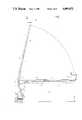
- FIG. 1is a side elevational view of an extensible and retractable boom machine having an aerial work platform mounted on the outermost end of a telescopic boom section, and employing the carrier track assembly of the present invention
- FIG. 2is a side elevational view of the boom sections in the retracted position
- FIG. 3is an enlarged side elevational view of the boom sections illustrated in FIG. 2, the drawing figure consisting of two portions which are joined longitudinally on the match line X-X;
- FIG. 4is a side elevational view of the boom sections in the extended position, the drawing figure consisting of two portions which are joined longitudinally on the match line Y-Y;
- FIG. 5is a view taken along line 5--5 of FIG. 3;
- FIG. 6is a view taken along line 6--6 of FIG. 3;
- FIG. 7is a view taken along line 7--7 of FIG. 3;
- FIG. 8is a view taken along line 8--8 of FIG. 3;
- FIG. 9is a view taken along line 9--9 of FIG. 3;
- FIG. 10is a view taken along line 10--10 of FIG. 2.
- FIG. 1by way of example an extensible and retractable boom machine is illustrated in which the carrier track assembly of the present invention is adapted to be employed.
- the machinecomprises a self-propelled steerable vehicular base 1 having a turntable 2 on which is mounted a horizontally turnable body portion 3.
- a counterweight 5is connected to one end of the body portion 3, and parallel linkages 6 are pivotally connected at their lower ends to the body portion 3, and at their upper ends to a frame member 7 to which the base section 8 of the boom is pivotally connected as at 9.
- a first luffing cylinder 10is provided between the body portion 3 and the linkages 6, and a second luffing cylinder 11 is provided between the frame member 7 and the base section 8, whereby the boom can be moved to various positions within a vertical plane.
- An extensible and retractable boom section 12is telescopically received within the base section 8 and the telescopic movement of the boom section is effected by a fluid cylinder 13 mounted within the base section 8 and a piston rod 14 extending from the cylinder 13 and having its outer end fixed to the boom section 12.
- An aerial platform 15is connected to the end of the boom section 12 and includes conventional controls for moving and steering the vehicular base 1, the luffing and sluing of the linkages 6 and boom base section 8, and the extension and retraction of the boom section 12, whereby a worker on the platform can control the position and reach of the telescopic boom assembly relative to an obstruction 16 in the vicinity of the work area.
- the various hoses and cables 17 for transmitting power to the aerial work platform 15extend into the base section 8 from the inner end thereof and are supported by a shelf 18 having convergent side walls 19 welded to the cylinder 13.
- the hoses and cables 17extend through a plurality of longitudinally spaced channels 20, bolted as at 21 to the shelf 18, to thereby retain the hoses and cables 17 on the shelf 18.
- a conventional flexible carrier track 22of the type disclosed in U.S. Pat. No. 4,129,277 to Tenniswood.
- the track 22has its inner end secured to the shelf 18 as at 23 and its outer end secured as at 24 to the inner end of the next adjacent boom section 12, the track 22 having a reversely bent or bight portion 25, whereby when the boom section 12 is extended, as shown in FIG. 4, the track 22 and associated hoses and cables 17 are supported on the shelf 18 secured to the cylinder 13.
- the boom section 12is retracted, as shown in FIG. 2, the track 22 is folded back on itself, to thereby shorten the effective length of the hoses and cables 17.
- an elevated support member 26is provided at a position between the inner end of the base section 8 and the track connection 23.
- the support membercomprises an inverted channel member having a web portion 27 upon which the track 22 rests, depending side walls 28, 29 secured to the edge portions of the shelf 18, and front and rear inclined wall portions 30, 31, respectively.
- a plurality of longitudinally spaced channels 32similar to channels 20, are bolted or otherwise suitably fastened to the top wall of boom section 12.
- the hoses and cables 17extend through the channels 32 to the work unit, such as, the aerial platform 15, on the end of the boom section 12.
- the carrier track 22 and associated hoses and cables 17are protectively housed within the boom sections 8 and 12 during the telescopic movement of the boom section 12, and the fluid cylinder 13 is employed for not only extending and retracting the boom section 12 but also as a support for the carrier track when the boom section is in an extended and retracted position.
- the carrier track 22thus consists of a bottom flight portion and a top flight portion joined by a reversely bent or rolling bight portion 25.
- the rolling bight portion 25moves outwardly away from its inner end 23 and away from the elevated support member 26, during which the length of the bottom flight portion increases while the length of the top flight portion decreases.
- the top flight portionslides outwardly over the top of web portion 27 of support member 26 and the outer end of the carrier track will eventually pass over the top of web portion 27.
- the length of the top flight portionwill be reduced to a length that is self supporting without appreciable sagging or with no sagging, and the bottom flight portion continues to increase in length and be laid in supported linear position on the shelf 18 in a direction outwardly from and away from elevated support member 26.
- the bottom flight portioncomprises substantially the full length of the carrier track, as shown in FIG. 4, and in this position the carrier track is substantially fully supported on the shelf 18 outwardly from and away from the elevated support member 26.
- Flexible carrier track 22is of a construction that is readily available from different manufacturers and may be constructed of metal or of plastics for greater saving in weight.
- the track linksare constructed to pivot relative to each other in one direction but not in the opposite direction so that the top flight is somewhat self supporting over short distances. Some track constructions will sag more than others in the retracted position of the boom and while a single elevated support member 26 is shown in the drawings, it is understood that two or more support members 26 may be provided, such as, for example, two additional elevated support members 26 connected over top of the channels 20 in FIG. 2 on each side of the single elevated support member 26 shown.
Landscapes
- Engineering & Computer Science (AREA)
- Structural Engineering (AREA)
- Mechanical Engineering (AREA)
- Life Sciences & Earth Sciences (AREA)
- Geology (AREA)
- Transportation (AREA)
- Civil Engineering (AREA)
- Forklifts And Lifting Vehicles (AREA)
- Jib Cranes (AREA)
- Movable Scaffolding (AREA)
- Automobile Manufacture Line, Endless Track Vehicle, Trailer (AREA)
Abstract
Description
Claims (12)
Priority Applications (9)
| Application Number | Priority Date | Filing Date | Title |
|---|---|---|---|
| US07/101,017US4809472A (en) | 1987-09-25 | 1987-09-25 | Carrier track assembly for extensible and retractable boom machines |
| EP88114871AEP0308758B1 (en) | 1987-09-25 | 1988-09-12 | Carrier track assembly for extensible and retractable boom machines |
| ES88114871TES2056863T3 (en) | 1987-09-25 | 1988-09-12 | SET OF CONVEYOR TRACK FOR EXTENSIBLE AND RETRACTABLE AGUILON MACHINES. |
| DE3850725TDE3850725T2 (en) | 1987-09-25 | 1988-09-12 | Device for carrying and guiding cables for devices with extendable and retractable arms. |
| CA000578083ACA1293456C (en) | 1987-09-25 | 1988-09-21 | Carrier track assembly for extensible and retractable boom machines |
| KR1019880012281AKR970007462B1 (en) | 1987-09-25 | 1988-09-22 | Carrier track assembly for extensible and retractable boom machines |
| AU22722/88AAU584023B1 (en) | 1987-09-25 | 1988-09-23 | Carrier track assembly for extensible and retractable boom machines |
| MX013145AMX165835B (en) | 1987-09-25 | 1988-09-23 | CONVEYOR TRACK ASSEMBLY FOR EXTENSIBLE AND RETRAIBLE BOOM MACHINES |
| JP23754888AJPH0729758B2 (en) | 1987-09-25 | 1988-09-24 | Carrier rack assembly for telescopic boom machine |
Applications Claiming Priority (1)
| Application Number | Priority Date | Filing Date | Title |
|---|---|---|---|
| US07/101,017US4809472A (en) | 1987-09-25 | 1987-09-25 | Carrier track assembly for extensible and retractable boom machines |
Publications (1)
| Publication Number | Publication Date |
|---|---|
| US4809472Atrue US4809472A (en) | 1989-03-07 |
Family
ID=22282693
Family Applications (1)
| Application Number | Title | Priority Date | Filing Date |
|---|---|---|---|
| US07/101,017Expired - LifetimeUS4809472A (en) | 1987-09-25 | 1987-09-25 | Carrier track assembly for extensible and retractable boom machines |
Country Status (9)
| Country | Link |
|---|---|
| US (1) | US4809472A (en) |
| EP (1) | EP0308758B1 (en) |
| JP (1) | JPH0729758B2 (en) |
| KR (1) | KR970007462B1 (en) |
| AU (1) | AU584023B1 (en) |
| CA (1) | CA1293456C (en) |
| DE (1) | DE3850725T2 (en) |
| ES (1) | ES2056863T3 (en) |
| MX (1) | MX165835B (en) |
Cited By (15)
| Publication number | Priority date | Publication date | Assignee | Title |
|---|---|---|---|---|
| US5054481A (en)* | 1990-08-29 | 1991-10-08 | Shin Hae Ryun | Infusion apparatus to supply compressed air into an industrial mask |
| EP0704406A1 (en) | 1994-09-27 | 1996-04-03 | Kidde Industries Inc. | Carrier track system for independent and/or synchronized operation of a multi-section telescopic boom structure |
| DE19613700A1 (en)* | 1996-03-29 | 1997-10-02 | M E P Gmbh Ges Fuer Consulting | Telescopically interlocking machine part, e.g. for excavator or crane |
| US6182995B1 (en)* | 1998-10-26 | 2001-02-06 | George B. Wall | Extendable semi-trailer |
| US6202831B1 (en)* | 1999-02-09 | 2001-03-20 | Wampfler Aktiengesellschaft | Work station feeding device |
| US20030127408A1 (en)* | 2000-01-21 | 2003-07-10 | National Crane Corporation | Anti-two block wire internal to crane telescopic boom |
| US20030205547A1 (en)* | 2002-05-03 | 2003-11-06 | Clark Equipment Company | Extendible boom with removable hydraulic hose carrier |
| US6758024B1 (en)* | 1999-11-24 | 2004-07-06 | Liebherr-Hydraulikbagger Gmbh | Industrial shaft, particularly for packaging equipment |
| US20090145690A1 (en)* | 2007-12-11 | 2009-06-11 | Gimaex International | High-Rise Aerial Apparatus and Vehicle Equipped Therewith |
| US20100200328A1 (en)* | 2009-02-06 | 2010-08-12 | Conception Gsr Inc. | Hydraulic boom system for vehicle |
| CN103510967A (en)* | 2013-10-12 | 2014-01-15 | 中联重科股份有限公司 | Telescopic boom and concrete sprayer |
| US9302708B2 (en) | 2013-09-20 | 2016-04-05 | Bull Moose Heavy Haul, Inc. | Support member for a trailer |
| US9539948B1 (en) | 2016-03-22 | 2017-01-10 | Jac Products, Inc. | Telescoping step assist system and method |
| US9791071B2 (en) | 2013-03-07 | 2017-10-17 | Oshkosh Corporation | Internally supported power track |
| US10723272B2 (en) | 2017-12-04 | 2020-07-28 | Jac Products, Inc. | Step rail system for vehicle |
Families Citing this family (4)
| Publication number | Priority date | Publication date | Assignee | Title |
|---|---|---|---|---|
| FR2699909B1 (en)* | 1992-12-28 | 1995-02-03 | Jean Diebolt | Telescopic crane boom, in particular folding crane. |
| DE202014105136U1 (en) | 2014-10-27 | 2014-11-06 | Igus Gmbh | Routing arrangement for a multi-telescopic boom with several thrust pieces |
| DE202017103858U1 (en) | 2017-06-28 | 2017-07-21 | Igus Gmbh | Arrangement with two cable drag chains and adjustable fixed point |
| DE102018109224A1 (en)* | 2018-04-18 | 2019-10-24 | Liebherr-Betonpumpen Gmbh | Concrete pump |
Citations (9)
| Publication number | Priority date | Publication date | Assignee | Title |
|---|---|---|---|---|
| US3937340A (en)* | 1974-06-14 | 1976-02-10 | Fulton Industries, Inc. | Aerial platform having boom mounted pipe holder |
| US4118907A (en)* | 1977-10-27 | 1978-10-10 | General Cable Corporation | Lifting equipment having telescopic boom with automatic extension limiting |
| US4129277A (en)* | 1977-02-07 | 1978-12-12 | Mcgraw-Edison Company | Retractable roller support for use with flexible rolling support for conductors or conduits |
| US4226300A (en)* | 1979-02-21 | 1980-10-07 | Mark Industries | Self propelled and extensible boom lift |
| US4360077A (en)* | 1980-07-02 | 1982-11-23 | Jlg Industries | Aerial lift platform apparatus with control conduit support system |
| GB2106860A (en)* | 1982-09-29 | 1983-04-20 | Coles Cranes Ltd | Improvements in and relating to telescopic booms |
| US4470229A (en)* | 1981-04-14 | 1984-09-11 | Coles Cranes Limited | Telescopic booms for cranes, access or load platforms or the like |
| US4506480A (en)* | 1983-03-10 | 1985-03-26 | Calavar Corporation | Extensible boom construction for self-propelled aerial work platforms |
| US4676340A (en)* | 1986-05-28 | 1987-06-30 | Pierce-Correll Corporation | Telescopic boom assembly having high dielectric properties |
Family Cites Families (2)
| Publication number | Priority date | Publication date | Assignee | Title |
|---|---|---|---|---|
| US4004695A (en)* | 1975-04-16 | 1977-01-25 | Fulton Industries, Inc. | Channel and plate telescopic crane boom |
| US4789120A (en)* | 1986-03-27 | 1988-12-06 | Kidde, Inc. | Carrier track system for extensible and retractable boom machines |
- 1987
- 1987-09-25USUS07/101,017patent/US4809472A/ennot_activeExpired - Lifetime
- 1988
- 1988-09-12DEDE3850725Tpatent/DE3850725T2/ennot_activeExpired - Fee Related
- 1988-09-12ESES88114871Tpatent/ES2056863T3/ennot_activeExpired - Lifetime
- 1988-09-12EPEP88114871Apatent/EP0308758B1/ennot_activeExpired - Lifetime
- 1988-09-21CACA000578083Apatent/CA1293456C/ennot_activeExpired - Lifetime
- 1988-09-22KRKR1019880012281Apatent/KR970007462B1/ennot_activeExpired - Fee Related
- 1988-09-23MXMX013145Apatent/MX165835B/enunknown
- 1988-09-23AUAU22722/88Apatent/AU584023B1/ennot_activeCeased
- 1988-09-24JPJP23754888Apatent/JPH0729758B2/ennot_activeExpired - Lifetime
Patent Citations (9)
| Publication number | Priority date | Publication date | Assignee | Title |
|---|---|---|---|---|
| US3937340A (en)* | 1974-06-14 | 1976-02-10 | Fulton Industries, Inc. | Aerial platform having boom mounted pipe holder |
| US4129277A (en)* | 1977-02-07 | 1978-12-12 | Mcgraw-Edison Company | Retractable roller support for use with flexible rolling support for conductors or conduits |
| US4118907A (en)* | 1977-10-27 | 1978-10-10 | General Cable Corporation | Lifting equipment having telescopic boom with automatic extension limiting |
| US4226300A (en)* | 1979-02-21 | 1980-10-07 | Mark Industries | Self propelled and extensible boom lift |
| US4360077A (en)* | 1980-07-02 | 1982-11-23 | Jlg Industries | Aerial lift platform apparatus with control conduit support system |
| US4470229A (en)* | 1981-04-14 | 1984-09-11 | Coles Cranes Limited | Telescopic booms for cranes, access or load platforms or the like |
| GB2106860A (en)* | 1982-09-29 | 1983-04-20 | Coles Cranes Ltd | Improvements in and relating to telescopic booms |
| US4506480A (en)* | 1983-03-10 | 1985-03-26 | Calavar Corporation | Extensible boom construction for self-propelled aerial work platforms |
| US4676340A (en)* | 1986-05-28 | 1987-06-30 | Pierce-Correll Corporation | Telescopic boom assembly having high dielectric properties |
Cited By (23)
| Publication number | Priority date | Publication date | Assignee | Title |
|---|---|---|---|---|
| US5054481A (en)* | 1990-08-29 | 1991-10-08 | Shin Hae Ryun | Infusion apparatus to supply compressed air into an industrial mask |
| EP0704406A1 (en) | 1994-09-27 | 1996-04-03 | Kidde Industries Inc. | Carrier track system for independent and/or synchronized operation of a multi-section telescopic boom structure |
| AU678728B2 (en)* | 1994-09-27 | 1997-06-05 | Jlg Industries, Inc. | Carrier track system for independent and/or synchronized operation of a multi-section telescopic boom structures |
| US5718345A (en)* | 1994-09-27 | 1998-02-17 | Kidde Industries, Inc. | Carrier track system for independent and/or synchronized operation of a multi-section telescopic boom structure |
| CN1043134C (en)* | 1994-09-27 | 1999-04-28 | 基德工业股份有限公司(美国) | Carrier track system for independent and/or synchronized operation of a muliti-section telescopic boom structure |
| DE19613700A1 (en)* | 1996-03-29 | 1997-10-02 | M E P Gmbh Ges Fuer Consulting | Telescopically interlocking machine part, e.g. for excavator or crane |
| US5924837A (en)* | 1996-03-29 | 1999-07-20 | Spitznas Maschinenfabrik Gmbh | Extensible telescopic machine part |
| US6182995B1 (en)* | 1998-10-26 | 2001-02-06 | George B. Wall | Extendable semi-trailer |
| US6202831B1 (en)* | 1999-02-09 | 2001-03-20 | Wampfler Aktiengesellschaft | Work station feeding device |
| US6758024B1 (en)* | 1999-11-24 | 2004-07-06 | Liebherr-Hydraulikbagger Gmbh | Industrial shaft, particularly for packaging equipment |
| US20030127408A1 (en)* | 2000-01-21 | 2003-07-10 | National Crane Corporation | Anti-two block wire internal to crane telescopic boom |
| US20030205547A1 (en)* | 2002-05-03 | 2003-11-06 | Clark Equipment Company | Extendible boom with removable hydraulic hose carrier |
| US7090086B2 (en)* | 2002-05-03 | 2006-08-15 | Clark Equipment Company | Extendible boom with removable hydraulic hose carrier |
| US20090145690A1 (en)* | 2007-12-11 | 2009-06-11 | Gimaex International | High-Rise Aerial Apparatus and Vehicle Equipped Therewith |
| US20100200328A1 (en)* | 2009-02-06 | 2010-08-12 | Conception Gsr Inc. | Hydraulic boom system for vehicle |
| US9791071B2 (en) | 2013-03-07 | 2017-10-17 | Oshkosh Corporation | Internally supported power track |
| US10174868B2 (en) | 2013-03-07 | 2019-01-08 | Oshkosh Corporation | Internally supported power track |
| US10989332B2 (en) | 2013-03-07 | 2021-04-27 | Oshkosh Corporation | Internally supported power track |
| US9302708B2 (en) | 2013-09-20 | 2016-04-05 | Bull Moose Heavy Haul, Inc. | Support member for a trailer |
| US9505440B2 (en) | 2013-09-20 | 2016-11-29 | Bull Moose Heavy Haul, Inc. | Support member for a trailer |
| CN103510967A (en)* | 2013-10-12 | 2014-01-15 | 中联重科股份有限公司 | Telescopic boom and concrete sprayer |
| US9539948B1 (en) | 2016-03-22 | 2017-01-10 | Jac Products, Inc. | Telescoping step assist system and method |
| US10723272B2 (en) | 2017-12-04 | 2020-07-28 | Jac Products, Inc. | Step rail system for vehicle |
Also Published As
| Publication number | Publication date |
|---|---|
| ES2056863T3 (en) | 1994-10-16 |
| EP0308758A3 (en) | 1990-08-08 |
| EP0308758B1 (en) | 1994-07-20 |
| DE3850725T2 (en) | 1994-10-27 |
| JPH01117199A (en) | 1989-05-10 |
| JPH0729758B2 (en) | 1995-04-05 |
| EP0308758A2 (en) | 1989-03-29 |
| KR970007462B1 (en) | 1997-05-09 |
| DE3850725D1 (en) | 1994-08-25 |
| MX165835B (en) | 1992-12-07 |
| CA1293456C (en) | 1991-12-24 |
| AU584023B1 (en) | 1989-05-11 |
| KR890004976A (en) | 1989-05-11 |
Similar Documents
| Publication | Publication Date | Title |
|---|---|---|
| US4809472A (en) | Carrier track assembly for extensible and retractable boom machines | |
| US4789120A (en) | Carrier track system for extensible and retractable boom machines | |
| US6516917B1 (en) | Outrigger assembly for a mobile telescopic belt conveyor | |
| US3776367A (en) | Mobile aerial platform | |
| EP0704406B1 (en) | Carrier track system for independent and/or synchronized operation of a multi-section telescopic boom structure | |
| US3845596A (en) | Drive system for a telescopic boom | |
| US6463958B1 (en) | Distributing device for thick substances, especially concrete | |
| US4094381A (en) | Aerial extension ladder | |
| US5005714A (en) | Crane, in particular a large mobile crane | |
| US4091936A (en) | Apparatus for extending a boom assembly | |
| JPS6220929B2 (en) | ||
| US3478894A (en) | Extensible and retractable boom construction for cranes | |
| US5494397A (en) | Load handling apparatus | |
| US4206833A (en) | Mobile aerial tower | |
| US3997029A (en) | Carriage hoisting arrangement for a lift truck | |
| EP0181399B1 (en) | Apparatus for moving crane vehicle laterally | |
| US4222492A (en) | Method for extending a boom assembly | |
| FI65054B (en) | ANORDNING VID LASTAPPARAT | |
| GB1440804A (en) | Access equipment | |
| JP4264311B2 (en) | Telescopic boom | |
| JPH0444546Y2 (en) | ||
| JP2558943Y2 (en) | Telescopic boom device | |
| JPH0322237Y2 (en) | ||
| JPS6127909Y2 (en) | ||
| JPH0628553Y2 (en) | Aerial work vehicle |
Legal Events
| Date | Code | Title | Description |
|---|---|---|---|
| AS | Assignment | Owner name:KIDDE, INC., PARK 80 WEST, PLAZA TWO, BOX 5555, SA Free format text:ASSIGNMENT OF ASSIGNORS INTEREST.;ASSIGNORS:HADE, DONALD C. JR.;BACKER, ROBERT D.;REEL/FRAME:004804/0535 Effective date:19870917 Owner name:KIDDE, INC., PARK 80 WEST, PLAZA TWO, BOX 5555, SA Free format text:ASSIGNMENT OF ASSIGNORS INTEREST;ASSIGNORS:HADE, DONALD C. JR.;BACKER, ROBERT D.;REEL/FRAME:004804/0535 Effective date:19870917 | |
| STCF | Information on status: patent grant | Free format text:PATENTED CASE | |
| AS | Assignment | Owner name:KIDDE INDUSTRIES, INC. Free format text:CHANGE OF NAME;ASSIGNOR:HKID 45 INC.;REEL/FRAME:005208/0907 Effective date:19880405 Owner name:KIDDE, INC., A DE CORP. Free format text:MERGER;ASSIGNORS:KIDDE, INC., A DE CORP. (MERGED INTO);HIMP-2 INC., A DE CORP. (CHANGED TO);REEL/FRAME:005208/0890;SIGNING DATES FROM 19880402 TO 19890821 Owner name:KIDDE INDUSTRIES, INC. Free format text:CHANGE OF NAME;ASSIGNOR:BLOOM-1 INC.;REEL/FRAME:005208/0846 Effective date:19881107 | |
| FPAY | Fee payment | Year of fee payment:4 | |
| FPAY | Fee payment | Year of fee payment:8 | |
| AS | Assignment | Owner name:CHASE BANK OF TEXAS, NATIONAL ASSOCIATION, AS ADMI Free format text:SECURITY INTEREST;ASSIGNORS:GROVE HOLDINGS LLC (DE LIMITED LIABLITY CORPORATION);GROVE WORLDWIDE LLC (DE LIMITED LIABILITY CORP.);GROVE CAPITAL, INC. (DE CORPORATION);AND OTHERS;REEL/FRAME:009342/0001 Effective date:19980429 | |
| AS | Assignment | Owner name:GROVE U.S. L.L.C., PENNSYLVANIA Free format text:ASSIGNMENT OF ASSIGNORS INTEREST;ASSIGNOR:KIDDE INDUSTRIES, INC.;REEL/FRAME:009463/0144 Effective date:19980429 | |
| FEPP | Fee payment procedure | Free format text:PAYOR NUMBER ASSIGNED (ORIGINAL EVENT CODE: ASPN); ENTITY STATUS OF PATENT OWNER: LARGE ENTITY | |
| FPAY | Fee payment | Year of fee payment:12 | |
| AS | Assignment | Owner name:CHASE MANHATTAN BANK, AS ADMINISTRATIVE AGENT, TH Free format text:SECURITY AGREEMENT;ASSIGNOR:GROVE U.S. LLC (DE LIMITED LIABILITY COMPANY);REEL/FRAME:012391/0248 Effective date:20010925 | |
| AS | Assignment | Owner name:HSBC INERNATIONAL TRADE FINANCE LIMITED, UNITED KI Free format text:SECURITY AGREEMENT AND AMENDMENT;ASSIGNOR:GROVE U.S. LLC;REEL/FRAME:012683/0080 Effective date:20010111 | |
| FEPP | Fee payment procedure | Free format text:PAYOR NUMBER ASSIGNED (ORIGINAL EVENT CODE: ASPN); ENTITY STATUS OF PATENT OWNER: LARGE ENTITY Free format text:PAYER NUMBER DE-ASSIGNED (ORIGINAL EVENT CODE: RMPN); ENTITY STATUS OF PATENT OWNER: LARGE ENTITY | |
| AS | Assignment | Owner name:JLG INDUSTRIES, INC., MARYLAND Free format text:ASSIGNMENT OF ASSIGNORS INTEREST;ASSIGNOR:GROVE U.S. L.L.C.;REEL/FRAME:016651/0784 Effective date:20040430 | |
| AS | Assignment | Owner name:SUNTRUST BANK, AS COLLATERAL AGENT, GEORGIA Free format text:SECURITY INTEREST;ASSIGNOR:JLG INDUSTRIES, INC.;REEL/FRAME:017215/0474 Effective date:20051130 | |
| AS | Assignment | Owner name:GROVE U.S. LLC, PENNSYLVANIA Free format text:RELEASE BY SECURED PARTY;ASSIGNOR:JPMORGAN CHASE BANK, N.A., AS COLLATERAL AGENT;REEL/FRAME:037900/0118 Effective date:20160303 Owner name:GROVE FINANCE LLC, PENNSYLVANIA Free format text:RELEASE BY SECURED PARTY;ASSIGNOR:JPMORGAN CHASE BANK, N.A., AS COLLATERAL AGENT;REEL/FRAME:037900/0118 Effective date:20160303 Owner name:GROVE WORLDWIDE LLC, PENNSYLVANIA Free format text:RELEASE BY SECURED PARTY;ASSIGNOR:JPMORGAN CHASE BANK, N.A., AS COLLATERAL AGENT;REEL/FRAME:037900/0118 Effective date:20160303 Owner name:CRANE HOLDING INC., PENNSYLVANIA Free format text:RELEASE BY SECURED PARTY;ASSIGNOR:JPMORGAN CHASE BANK, N.A., AS COLLATERAL AGENT;REEL/FRAME:037900/0118 Effective date:20160303 Owner name:GROVE CAPITAL LLC, PENNSYLVANIA Free format text:RELEASE BY SECURED PARTY;ASSIGNOR:JPMORGAN CHASE BANK, N.A., AS COLLATERAL AGENT;REEL/FRAME:037900/0118 Effective date:20160303 Owner name:GROVE HOLDINGS LLC, PENNSYLVANIA Free format text:RELEASE BY SECURED PARTY;ASSIGNOR:JPMORGAN CHASE BANK, N.A., AS COLLATERAL AGENT;REEL/FRAME:037900/0118 Effective date:20160303 Owner name:CRANE ACQUISITION CORPORATION, PENNSYLVANIA Free format text:RELEASE BY SECURED PARTY;ASSIGNOR:JPMORGAN CHASE BANK, N.A., AS COLLATERAL AGENT;REEL/FRAME:037900/0118 Effective date:20160303 Owner name:GROVE U.S., L.L.C., PENNSYLVANIA Free format text:RELEASE BY SECURED PARTY;ASSIGNOR:JPMORGAN CHASE BANK, N.A., AS COLLATERAL AGENT;REEL/FRAME:037899/0208 Effective date:20160303 | |
| AS | Assignment | Owner name:GROVE U.S. L.L.C., PENNSYLVANIA Free format text:RELEASE BY SECURED PARTY;ASSIGNOR:HSBC INTERNATIONAL TRADE FINANCE LIMITED;REEL/FRAME:039241/0072 Effective date:20160721 |