US4807462A - Method for performing automatic calibrations in an electronic compass - Google Patents
Method for performing automatic calibrations in an electronic compassDownload PDFInfo
- Publication number
- US4807462A US4807462AUS07/034,134US3413487AUS4807462AUS 4807462 AUS4807462 AUS 4807462AUS 3413487 AUS3413487 AUS 3413487AUS 4807462 AUS4807462 AUS 4807462A
- Authority
- US
- United States
- Prior art keywords
- vehicle
- automatic calibration
- magnetic field
- earth
- calibration method
- Prior art date
- Legal status (The legal status is an assumption and is not a legal conclusion. Google has not performed a legal analysis and makes no representation as to the accuracy of the status listed.)
- Expired - Lifetime
Links
- 238000000034methodMethods0.000titleclaimsabstractdescription65
- 230000000694effectsEffects0.000claimsabstractdescription6
- 230000004907fluxEffects0.000claimsdescription4
- 230000001360synchronised effectEffects0.000claims1
- 230000008569processEffects0.000abstractdescription14
- 239000013598vectorSubstances0.000description23
- 230000006872improvementEffects0.000description3
- 238000005259measurementMethods0.000description3
- 230000003321amplificationEffects0.000description2
- 230000008901benefitEffects0.000description2
- 238000001914filtrationMethods0.000description2
- 238000003199nucleic acid amplification methodMethods0.000description2
- 230000008859changeEffects0.000description1
- 238000004519manufacturing processMethods0.000description1
- 239000002184metalSubstances0.000description1
- 230000004048modificationEffects0.000description1
- 238000012986modificationMethods0.000description1
- 230000000737periodic effectEffects0.000description1
- 238000004451qualitative analysisMethods0.000description1
- 230000004044responseEffects0.000description1
- 238000000926separation methodMethods0.000description1
Images


Classifications
- G—PHYSICS
- G01—MEASURING; TESTING
- G01C—MEASURING DISTANCES, LEVELS OR BEARINGS; SURVEYING; NAVIGATION; GYROSCOPIC INSTRUMENTS; PHOTOGRAMMETRY OR VIDEOGRAMMETRY
- G01C17/00—Compasses; Devices for ascertaining true or magnetic north for navigation or surveying purposes
- G01C17/38—Testing, calibrating, or compensating of compasses
Definitions
- This inventionrelates to automatically calibrating an electronic compass in a vehicle, especially an automotive vehicle.
- the inventioneliminates the need for an intervention by the operator of the vehicle in the calibration process.
- the calibrationis done automatically thereby reducing chances for error and providing a more accurate calibration on a continuous or periodic basis without the intervention of the operator of the vehicle.
- the subject inventionis closely related to and is an improvement to the system described in commonly assigned U.S. Pat. No. 4,622,843 to Hormel on Nov. 18, 1986 and two other commonly assigned U.S. patent applications, U.S. Ser. No. 06/814,125 (now U.S. Pat. No. 4,677,754; 07/07/87), "The Multiplexing Of A Bandpass Filter Circuit To Work With A Flux-Gate Sensor Output” also to Hormel, and U.S. Ser. No. 06/814,133, now U.S. Pat. No. 4,750,349; 6/14/88, "Microcomputer Controlled Quick Ranging Technique And Digital Filter” to Luitje. All three of these documents were filed in the U.S. Patent & Trademark Office on Dec. 27, 1985 and the entire contents of these three documents are hereby expressly incorporated by reference.
- the subject inventionis an improvement to the calibration method claimed in co-pending, commonly assigned U.S. Ser. No. 06/931,766, now U.S. Pat. No. 4,720,992; 1/26/88, "Calibration Sequence And Method For An Electronic Compass,” filed on Nov. 17, 1986, which is also hereby expressly incorporated by reference.
- the method and system described hereincalls for the calibration of an electronic compass without using the operator of the vehicle in the process.
- the operator of the vehiclewas involed in the calibration process by supplying information and/or by becoming actively involved with the process by orienting the vehicle in a predetermined format.
- the subject inventioneliminates the need for the operator of the vehicle to help to supply information relating to the earth's unknown magnetic field as sensed from the frame of reference of the vehicle in which the electronic compass resides.
- the methoddoes not need to make use of the unknown magnetic field due to the earth (as sensed from the frame of reference of the vehicle in which the electronic compass resides) in the process of automatically calibrating the compass.
- This magnetic fieldalthough unknown, is utilized by viewing the position of the vehicle with respect to the earth's field, thereby eliminating the effect on the compass computation of the earth's magnetic field as sensed in the vehicle.
- the methodessentially takes advantage of the mathematical principles involved with perpendicular bisectors to chords of a circle to compute the center of the earth's field circle, independent of the magnetic field generated by the vehicle itself.
- the chordsdefine points measured by the electronic compass, and contained on a circle whose center is the tip of a magnetic field vector due to the vehicle's magnetic field with respect to the earth's magnetic field as sensed in the flux-gate sensor of the vehicle.
- the subject inventionfinds an origin which is a zero output of the magnetic flux-gate sensor which outputs a zero in the situation of a net resultant of zero magnetic field as detected by the magnetic flux-gate sensor.
- the inventionfurther seeks to use the found center of the earth's magnetic field circle to compute the directional offset values used in the magnetic compass heading computations as described in the '843 patent to Hormel and, more specifically shown in blocks 368 and 370 and the accompanying description and figures of the '843 patent which has been incorporated by reference. Further attention is invited to the description in column 13 of the '843 patent circa lines 47-64.
- the present applicationdiscloses a method of improve upon the manual, mirrored 180 degree re-orientation calibration sequence/method by eliminating the need for operator involvement in the calibration process. It eliminates the need to turn the vehicle in any prescribed manner or sequence and eliminates the need to push switches or buttons in response to prompts from the microprocessor controlling the compass.
- the calibration processis performed automatically, as called for continuously or periodically by the microprocessor thereby improving the accuracy of the compass.
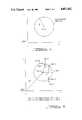
- FIG. 1shows cartesian X,Y axes with a defined point origin representing a zero magnetic field as sensed by the flux gate, also shown is the earth's field circle with center X 0 , Y 0 and the vector "R" which represents the radius of the earth's field circle;
- FIG. 2shows the same cartesian axes, the earth's field circle, two chords and perpendicular bisectors of each chord;
- FIG. 3illustrates the turning of a vehicle during a manual calibration of a vehicle compass
- FIG. 4illustrates vehicle movement typical of that observed during an automatic calibration of a vehicle's electronic compass according to the present invention
- FIG. 5is a flowchart of the method of automatic calibration of a vehicle compass disclosed herein.
- FIG. 6is a flowchart showing an alternative method of automatic calibration of a vehicle compass disclosed herein.
- Cartesian X,Y axesare illustrated, along with the defined origin representing a sensed zero magnetic field from the flux-gate 42 as shown in FIG. 1 and FIG. 2A of the Hormel/Luitje documents incorporated by reference.
- FIG. 1Also illustrated in FIG. 1 is the earth's field circle and its center represented by the Cartesian coordinates (X 0 , Y 0 ).
- FIG. 2the same Cartesian axes are illustrated, along with the earth's field circle and its center (X 0 , Y 0 ).
- X 0 , Y 0the same Cartesian axes are illustrated, along with the earth's field circle and its center (X 0 , Y 0 ).
- two chords of the earth's field circleare represented as lines M and N.
- Line Mis formed by point 1 and point 2 on the circumference of the earth's field circle
- line Nis defined by point 2 and point 3, also a chord of the earth's field circle.
- Point 1point 2 and point 3 are three location points as read by the electronic compass as the vehicle moves about its journey. In other words, as the vehicle turns direction a new point is measured and captured through the use of the electronic compass as described in the documents incorporated by reference. These three points are utilized in the auto-calibration procedure described herein.
- the perpendicular bisector of a chord of a circleintersects other perpendicular bisectors of other chords of the same circle at the center of the circle. Therefore, the center of the circle (X 0 , Y 0 ) can be defined by line K and line L.
- intersection of these two perpendicular bisectorsis the center of the circle (X 0 , Y 0 ). More than three points can be utilized for this purpose and an example utilizing four points is shown in the following description, but the theory remains the same.
- the method described here for calibrating an electronic compass(which is actually finding the location of the center of the circle spanning by the earth's field), when incorporated, allows an automatic process of continuously updating the center of the earth's circle whenever the vehicle (which has the compass on it) makes any turn. This means that the compass continuously calibrates itself while driving the vehicle and its does it on its own without interference from the driver.
- the earth's magnetic field sensed by an electronic compass in a vehicle, with a present sheet metal magnetic field,is a vector that spans a circle. As the car turns, the vector spans the earth's field circle. This is shown in FIG. 1.
- the calibration process of such a fieldis done by finding the center of the earth's field circle (X 0 , Y 0 ).
- the center of a circleis the intersection point of the two lines perpendicular to two line sectors on the circumference of the circle given that each one of the two perpendicular lines must pass through the midpoint of the corresponding sector line perpendicular to it. This is shown in FIG. 2.
- the center point of a circlecan be found from solving for the intersection point of two non-parallel line equations K, L.
- These two line equationsare the orthogonal line equations for two different line equations M, N.
- Line Mpasses through point 1 and point 2 whereas line N passes through point 2 and point 3.
- the two lines K, Lmust pass through the midpoint of lines M, N, respectively. This is shown in FIG. 2.
- the following equationsdescribe quantitatively how (X 0 , Y 0 ) is obtained given only three points P1, P2 and P3.
- the now known center (x 0 ,y 0 )is used to compute the directional offset values used in the magnetic compass heading computations as described in the '843 patent to Hormel and, more specifically shown in block 368 and block 370 and in the accompanying description and figures of the '843 patent which has been incorporated by reference.
- Calibrationis necessary to separate the vehicle's magnetic field from that of the earth's magnetic field so that the earth's field can be measured and used to give vehicle direction.
- the earth's magnetic fieldis stationary to the earth, but the vehicle's magnetic field is stationary to the vehicle.
- the magnetic fieldsare measured as vectors with direction and magnitude on each.
- the compassmeasures only the resultant of the summation of the two vectors which is the sum of the earth's and the vehicle's magnetic fields. When the two vectors of equal magnitude and opposite direction (180 degrees apart) are added together, the resultant is zero (0).
- the compassmeasures the magnetic field relative to the vehicle when these vectors are added together according to the formulas described in the specification.
- the compass calibration sequencestarts with the vehicle in any direction and actuation of the calibration button by the operator of the vehicle. At this first point, the compass electronics measures and records the resultant magnetic field.
- the vehicleis then moved to a second location which is rotated 180 degrees from the first location.
- the calibration buttonis re-actuated by the operator of the vehicle and the resultant magnetic field is again measured and recorded.
- Vthe vehicle offset which is, in other words, the vehicle's magnetic field which is subtracted from any compass reading that the electronic compass, as described elsewhere in the '843 and '766 specifications, reads and computes.
- the present inventioncalibrates the electronic compass without operator intervention and computes a vehicle offset vector "V."
- This vectorrepresents the vehicle's magnetic field with respect to the earth's magnetic field.
- Vector "V”is subtracted from any compass reading.
- Vehicle offset vector "V”is shown on FIG. 2 with its beginning point at the origin and its ending point at (x 0 ,y 0 ). This means that the axes shown in FIG. 1 and FIG. 2 represent the frame of reference of the vehicle as viewed (sensed) by the flux gate sensor.
- the vector "R” as shown in FIG. 1is the radius of the earth's field circle.
- FIG. 3shown is a way to calibrate the compass with a mirrored 180 degree turn of the vehicle and operator involvement.
- Two points, a and b,are measured.
- the magnetic field sensed by the compasschanges from point a to point b when the vehicle is turned 180 degrees.
- This type of calibrationis explained herein in the summary of the invention section and in commonly assigned application Ser. No. 06/931,766 filed on Nov. 17, 1986, now U.S. Pat. No. 4,720,992; 1/26/88 which has been incorporated by reference.
- the operatorpositions the manual calibration by pushing a button and awaiting the compass to tell him to turn the car to a predetermined 180 degree line.
- the operatorpushes a button to let the compass know that he turned the car 180 degrees and the compass finishes the calibration. Note also that if the turn is not equal to 180 degrees, the calibration is incorrect.
- FIG. 4shown is the movement of a vehicle equipped with an electronic compass. Also shown are the points sensed by the electronic compass during the automatic calibration. Each position the vehicle takes is assigned a magnetic field point by the compass. The angle theta between vehicle positions is equal to the angle theta on the circle. The same thing is true for angle phi, where theta and phi could be any value so long as theta is not equal to phi.
- the electronic compassdoes the calibration automatically, on its own, every time the vehicle takes a different route while driven. That is, a random route is perfectly acceptable and replaces the predetermined 180 degree turn of some other systems and of a predetermined 360 degree turn of still other systems. Therefore, the compass is continuously updating its calibration value.
- the calibrationis totally independent of the operator and therefore is always accurate. Of course, the operator can be allowed to request a calibration at any time but such is merely for operator satisfaction as the automatic calibration is performed continuously as presently envisioned in the subject embodiment.
- the direction the vehicle takesis unimportant for the calibration.
- the direction of sweep of radius vector between (x 0 ,y 0 ) and the circumference of the earth's field circleis unimportant. All that is necessary to know is the point the flux gate senses on the field circle as the vehicle changes direction. That is, since the x,y coordinates are used, the direction of sweep between the angles is not important, only the magnitude and direction of the resultant radius vector of the field circle.
- the angles theta and phiwill not exceed 180 degrees due to structure of the electronics as described in the documents incorporated by reference.
- FIG. 5A and FIG. 5B of the '843 patentBefore referring to FIG. 5 in the subject application, attention is invited to FIG. 5A and FIG. 5B of the '843 patent to Hormel.
- the subject inventioncan be used in the same system described in the '843 patent and will find itself supplanting all of the software calibration and ranging technique blocks as shown in FIGS. 5A and 5B of the '843 patent stopping at block 368. In other words, the following description will be the blocks preceding the blocks 368 and 370 in FIG. 5B of the '843 patent.
- the automatic calibration procedureis begun in block 500.
- the compass calibrationis checked in block 502. This is done by reading a preset flag in the memory of microprocessor 10 as shown in the '843 patent. This is a flag and is a preset initial calibration condition. It represents a condition that will never occur in the use of the compass and it will indicate that the compass is out of calibration. This preset condition is only used when the electronic compass is first energized after manufacturing. Thereafter, the calibration is updated with the automatic calibration sequence as described below.
- the procedurefalls through to block 504 to place the point that represents the current measurement of the heading of the vehicle as measured by the electronic compass system near the origin of the Cartesian axes as shown on FIG. 1 and FIG. 2. This is done as described in the documents incorporated by reference.
- the procedurecalls for the reading of point 1 and the reading of point 2 by the electronic compass system, each point being captured in memory after a turn in direction by the vehicle, thereby defining points on a circle. This is done in block 506.
- the microprocessor 10calculates the center of the earth's magnetic field circle (X 0 , Y 0 ) according to the formula shown above in the description of this invention, while at the same time, updating the direction and filtering the readings as described in the '843 patent, which has been incorporated herein by reference.
- the procedurefalls through to block 512 to check the center of the earth's magnetic field circle (X 0 , Y 0 ) to see if it is near the origin. If it is, the method branches to block 514 to redefine point 2 as point 1 and then to redefine point 3 as point 2 proceeding next back through block 508 to read a new point 3 and continue with the procedure from there.
- the methodbranches back to block 504 to place the point currently being measured near the origin and to begin the procedure once again.
- the purpose of this moving of the point being measured to a point near the originis to allow for the maximum earth's magnetic field circle that can be measured in the defined graph of the Cartesian axes X and Y. The larger the graph, the more accurate the calibration.
- FIG. 6represents an alternative embodiment of the method shown in FIG. 5.
- the item numbersare analogous to that done for FIG. 5 except for the use of block 616 which has no analog in FIG. 5.
- Each block in FIG. 6has a corresponding block in FIG. 5. with the exact same step included except for the addition of performing some of the steps while updating direction and filtering information as described with respect to block 510. These blocks are marked with an asterisk.
- Block 616actually places (X 0 ,Y 0 ) near the origin of the axes as opposed to waiting for the method in FIG. 5 to bring (X 0 ,Y 0 ) to the origin.
- Block 616can be done using quick ranging techniques as described in the documents incorporated by reference.
Landscapes
- Engineering & Computer Science (AREA)
- Radar, Positioning & Navigation (AREA)
- Remote Sensing (AREA)
- Physics & Mathematics (AREA)
- General Physics & Mathematics (AREA)
- Measuring Magnetic Variables (AREA)
Abstract
Description
y=[(y.sub.2 -y.sub.1)/(x.sub.2 -x.sub.1)]x+y.sub.1 -[(y.sub.2 -y.sub.1)/(x.sub.2 -x.sub.1)]x.sub.1EQ 1
y=mx+b,EQ 2
y=-(x/m)+k EQ 3
y=-(x/m)+y.sub.i +(x.sub.i /m)EQ 4
y=m.sub.1 x+b.sub.1
y=m.sub.2 x+b.sub.2
m.sub.1 x+b.sub.1 =m.sub.2 x+b.sub.2
x(m.sub.1 -m.sub.2)=b.sub.2 -b.sub.1 or
x=[(b.sub.2 -b.sub.1)/(m.sub.1 -m.sub.2)]=x.sub.0 EQ 5 and
y.sub.0 -m.sub.1 x.sub.0 +b.sub.1 EQ 6
y=[(y.sub.2 -y.sub.1)/(x.sub.2 -x.sub.1)]x+y.sub.1 -[(y.sub.2 -y.sub.1)/(x.sub.2 -x.sub.1)]x.sub.1 ; EQ 7
y=[(y.sub.4 -y.sub.3)/(x.sub.4 -x.sub.3)]x+y.sub.3 -[(y.sub.4 -y.sub.3)/(x.sub.4 -x.sub.3)]x.sub.3); EQ 8
{Line K}: y=(-x/m.sub.1)+y.sub.a +(x.sub.a /m.sub.1); EQ 9{Line L}: y=(-x/m.sub.2)+y.sub.b +(x.sub.b /m.sub.2); EQ 10y.sub.0 =-[(x.sub.2 -x.sub.1)/(y.sub.2 -y.sub.1)]x.sub.0 +y.sub.a +[(x.sub.2 -x.sub.1)/(y.sub.2 -y.sub.1)]x.sub.a EQ 12
Claims (12)
Priority Applications (2)
| Application Number | Priority Date | Filing Date | Title |
|---|---|---|---|
| US07/034,134US4807462A (en) | 1987-04-03 | 1987-04-03 | Method for performing automatic calibrations in an electronic compass |
| CA000547755ACA1286496C (en) | 1987-04-03 | 1987-09-24 | Method for performing automatic calibrations in an electronic compass |
Applications Claiming Priority (1)
| Application Number | Priority Date | Filing Date | Title |
|---|---|---|---|
| US07/034,134US4807462A (en) | 1987-04-03 | 1987-04-03 | Method for performing automatic calibrations in an electronic compass |
Publications (1)
| Publication Number | Publication Date |
|---|---|
| US4807462Atrue US4807462A (en) | 1989-02-28 |
Family
ID=21874525
Family Applications (1)
| Application Number | Title | Priority Date | Filing Date |
|---|---|---|---|
| US07/034,134Expired - LifetimeUS4807462A (en) | 1987-04-03 | 1987-04-03 | Method for performing automatic calibrations in an electronic compass |
Country Status (2)
| Country | Link |
|---|---|
| US (1) | US4807462A (en) |
| CA (1) | CA1286496C (en) |
Cited By (40)
| Publication number | Priority date | Publication date | Assignee | Title |
|---|---|---|---|---|
| EP0451839A3 (en)* | 1990-04-12 | 1992-12-09 | Matsushita Electric Industrial Co., Ltd. | Direction finding apparatus |
| WO1993006434A1 (en)* | 1991-09-17 | 1993-04-01 | Siemens Aktiengesellschaft | Process for compensating a magnetic interference field in a vehicle |
| US5255442A (en)* | 1991-12-20 | 1993-10-26 | Donnelly Corporation | Vehicle compass with electronic sensor |
| US5287295A (en)* | 1991-05-30 | 1994-02-15 | Motorola | Method and apparatus for calibrating an electronic compass to account for alignment errors in the compass windings |
| US5297063A (en)* | 1991-12-27 | 1994-03-22 | Chrysler Corporation | Method for selecting calibration data for an auto-calibrating compass |
| US5351204A (en)* | 1991-12-27 | 1994-09-27 | Chrysler Corporation | Scaling system and method for an electronic compass |
| US5353241A (en)* | 1991-12-27 | 1994-10-04 | Al Attar Rafi A | Shifting system and method for an electronic compass system |
| US5390122A (en)* | 1993-05-07 | 1995-02-14 | Lectron Products, Inc. | Method and apparatus for calibrating a vehicle compass system |
| US5526022A (en)* | 1993-01-06 | 1996-06-11 | Virtual I/O, Inc. | Sourceless orientation sensor |
| GB2301900A (en)* | 1995-06-05 | 1996-12-18 | Prince Corp | Vehicle compass system with automatic calibration |
| US5644851A (en)* | 1991-12-20 | 1997-07-08 | Blank; Rodney K. | Compensation system for electronic compass |
| US5828984A (en)* | 1991-12-27 | 1998-10-27 | Chrysler Corporation | Data processing method for an electronic compass system |
| US5850624A (en)* | 1995-10-18 | 1998-12-15 | The Charles Machine Works, Inc. | Electronic compass |
| US5878370A (en)* | 1995-12-01 | 1999-03-02 | Prince Corporation | Vehicle compass system with variable resolution |
| US5991085A (en) | 1995-04-21 | 1999-11-23 | I-O Display Systems Llc | Head-mounted personal visual display apparatus with image generator and holder |
| US6009629A (en)* | 1996-03-13 | 2000-01-04 | Leica Geosystems Ag | Process for determining the direction of the earth's magnetic field |
| US6047237A (en)* | 1997-12-10 | 2000-04-04 | Prince Corporation | Compass precalibration method |
| US6192315B1 (en) | 1997-06-27 | 2001-02-20 | Prince Corporation | Dual-calibrated compass |
| US6301794B1 (en) | 1999-05-27 | 2001-10-16 | Johnson Controls, Inc. | Vehicle compass system with continuous automatic calibration |
| US6356851B1 (en) | 1999-02-05 | 2002-03-12 | Delphi Technologies, Inc. | Accelerated calibration for electronic compass module |
| US6445178B1 (en) | 1999-02-24 | 2002-09-03 | Donnelly Corporation | Vehicular magnetic displacement sensor for determining an offset in the output of the sensor |
| US20030013507A1 (en)* | 2001-07-10 | 2003-01-16 | Hideki Sato | Portable electronic apparatus with azimuth measuring function, magnetic sensor suitable for the apparatus, and azimuth measuring method for the apparatus |
| US6513252B1 (en) | 1999-04-08 | 2003-02-04 | Donnelly Corporation | Vehicle compass compensation |
| US20040123474A1 (en)* | 2002-12-30 | 2004-07-01 | Manfred Mark T. | Methods and apparatus for automatic magnetic compensation |
| US6760678B1 (en)* | 2000-04-11 | 2004-07-06 | Electronics Tomorrow Limited | Electronic compass |
| US20040236510A1 (en)* | 2002-03-01 | 2004-11-25 | Ockerse Harold C. | Electronic compass system |
| US20040254727A1 (en)* | 2002-03-01 | 2004-12-16 | Ockerse Harold C. | Electronic compass system |
| US6877237B1 (en)* | 2004-03-05 | 2005-04-12 | Honeywell International Inc. | Method and system for acquiring calibration data for an electronic compass |
| US20050223574A1 (en)* | 2004-04-07 | 2005-10-13 | Siemens Vdo Automotive Corporation | Electronic compass and method for tracking vehicle rotation |
| US20060168832A1 (en)* | 2004-10-07 | 2006-08-03 | Yamaha Corporation | Geomagnetic sensor and geomagnetic sensor correction method, temperature sensor and temperature sensor correction method, geomagnetism detection device |
| US20060190174A1 (en)* | 2005-02-24 | 2006-08-24 | Aichi Micro Intelligent Corporation | Electronic compass and direction finding method |
| US20070084070A1 (en)* | 2005-10-19 | 2007-04-19 | Aichi Micro Intelligent Corporation | Magnetic compass |
| US20070136020A1 (en)* | 2004-10-07 | 2007-06-14 | Yamaha Corporation | Geomagnetic sensor and geomagnetic sensor correction method, temperature sensor and temperature sensor correction method, geomagnetism detection device |
| WO2007129653A1 (en) | 2006-05-09 | 2007-11-15 | Alps Electric Co., Ltd. | Calibration program and electronic compass |
| US20100161272A1 (en)* | 2007-05-24 | 2010-06-24 | Masaya Yamashita | Physical amount measuring device and physical amount measuring method |
| CN101208578B (en)* | 2003-02-24 | 2010-12-08 | 金泰克斯公司 | Electronic compass system |
| US8321161B1 (en)* | 2010-09-17 | 2012-11-27 | The United States of America as represented by the Secretarty of the Navy | Autonomous magnetic measurement system |
| DE102016207665A1 (en) | 2016-05-03 | 2017-11-09 | Continental Automotive Gmbh | Method for calibrating magnetic field sensors |
| WO2020172245A1 (en)* | 2019-02-20 | 2020-08-27 | Crocus Technology Inc. | Apparatus and method for magnetic sensor output compensation based upon ambient temperature |
| DE102013226677B4 (en) | 2012-12-31 | 2022-06-30 | Amer Sports Digital Services Oy | METHOD AND DEVICE FOR DETERMINING DIRECTION IN A MAGNETIC FIELD |
Citations (19)
| Publication number | Priority date | Publication date | Assignee | Title |
|---|---|---|---|---|
| DE1964569A1 (en)* | 1968-12-26 | 1970-07-09 | Sperry Rand Corp | Magnetic compass system |
| US3683668A (en)* | 1971-01-26 | 1972-08-15 | Sperry Rand Corp | Compass calibrator |
| US3899834A (en)* | 1972-10-02 | 1975-08-19 | Westinghouse Electric Corp | Electronic compass system |
| US3943763A (en)* | 1974-12-11 | 1976-03-16 | The United States Of America As Represented By The United States National Aeronautics And Space Administration Office Of General Counsel-Code Gp | Magnetic heading reference |
| US3991361A (en)* | 1975-03-27 | 1976-11-09 | Westinghouse Electric Corporation | Semi-automatic compass calibrator apparatus for a vehicle mounted flux gate compass system to cancel out effect of local magnetic disturbances |
| US4143467A (en)* | 1978-05-01 | 1979-03-13 | Sperry Rand Corporation | Semi-automatic self-contained magnetic azimuth detector calibration apparatus and method |
| US4227404A (en)* | 1978-04-17 | 1980-10-14 | Century Geophysical Corporation | Digital mineral logging system |
| US4347730A (en)* | 1979-01-22 | 1982-09-07 | The United States Of America As Represented By The Secretary Of The Army | Method and apparatus for calibrating gyroscopically-stabilized, magnetically-slaved heading reference system |
| US4424631A (en)* | 1982-03-02 | 1984-01-10 | Prince Corporation | Electrical compass |
| US4425717A (en)* | 1982-06-24 | 1984-01-17 | Prince Corporation | Vehicle magnetic sensor |
| US4505054A (en)* | 1983-05-25 | 1985-03-19 | Prince Corporation | Magnetic sensor mounting system |
| US4539760A (en)* | 1982-10-12 | 1985-09-10 | Plessey Overseas Ltd. | Compass |
| US4546551A (en)* | 1983-03-24 | 1985-10-15 | Prince Corporation | Electrical control system |
| US4611293A (en)* | 1983-11-28 | 1986-09-09 | Magnavox Government And Industrial Electronics Company | Method and apparatus for automatic calibration of magnetic compass |
| US4622646A (en)* | 1982-09-08 | 1986-11-11 | The Commonwealth Of Australia Of C/-Department Of Defence Support | Arrangements for correcting compasses |
| US4622843A (en)* | 1985-12-27 | 1986-11-18 | Hormel Ronald F | Simplified calibration technique and auto ranging circuit for an electronic compass control circuit |
| US4677754A (en)* | 1985-12-27 | 1987-07-07 | Chrysler Motors Corporation | Multiplexing of a bandpass filter circuit to work with a flux-gate sensor output |
| US4738031A (en)* | 1985-03-13 | 1988-04-19 | Alberter Guenter | Method for establishing the driving direction of a vehicle with an electronic compass |
| US4750349A (en)* | 1985-12-27 | 1988-06-14 | Chrysler Motors Corporation | Microcomputer controlled quick ranging technique and digital filter |
- 1987
- 1987-04-03USUS07/034,134patent/US4807462A/ennot_activeExpired - Lifetime
- 1987-09-24CACA000547755Apatent/CA1286496C/ennot_activeExpired - Fee Related
Patent Citations (21)
| Publication number | Priority date | Publication date | Assignee | Title |
|---|---|---|---|---|
| DE1964569A1 (en)* | 1968-12-26 | 1970-07-09 | Sperry Rand Corp | Magnetic compass system |
| US3683668A (en)* | 1971-01-26 | 1972-08-15 | Sperry Rand Corp | Compass calibrator |
| US3899834A (en)* | 1972-10-02 | 1975-08-19 | Westinghouse Electric Corp | Electronic compass system |
| US3943763A (en)* | 1974-12-11 | 1976-03-16 | The United States Of America As Represented By The United States National Aeronautics And Space Administration Office Of General Counsel-Code Gp | Magnetic heading reference |
| US3991361A (en)* | 1975-03-27 | 1976-11-09 | Westinghouse Electric Corporation | Semi-automatic compass calibrator apparatus for a vehicle mounted flux gate compass system to cancel out effect of local magnetic disturbances |
| US4227404A (en)* | 1978-04-17 | 1980-10-14 | Century Geophysical Corporation | Digital mineral logging system |
| US4143467A (en)* | 1978-05-01 | 1979-03-13 | Sperry Rand Corporation | Semi-automatic self-contained magnetic azimuth detector calibration apparatus and method |
| US4347730A (en)* | 1979-01-22 | 1982-09-07 | The United States Of America As Represented By The Secretary Of The Army | Method and apparatus for calibrating gyroscopically-stabilized, magnetically-slaved heading reference system |
| US4424631A (en)* | 1982-03-02 | 1984-01-10 | Prince Corporation | Electrical compass |
| US4425717A (en)* | 1982-06-24 | 1984-01-17 | Prince Corporation | Vehicle magnetic sensor |
| US4622646A (en)* | 1982-09-08 | 1986-11-11 | The Commonwealth Of Australia Of C/-Department Of Defence Support | Arrangements for correcting compasses |
| US4539760A (en)* | 1982-10-12 | 1985-09-10 | Plessey Overseas Ltd. | Compass |
| US4546550A (en)* | 1982-10-12 | 1985-10-15 | Plessey Overseas Ltd. | Compass |
| US4546551A (en)* | 1983-03-24 | 1985-10-15 | Prince Corporation | Electrical control system |
| US4505054A (en)* | 1983-05-25 | 1985-03-19 | Prince Corporation | Magnetic sensor mounting system |
| US4611293A (en)* | 1983-11-28 | 1986-09-09 | Magnavox Government And Industrial Electronics Company | Method and apparatus for automatic calibration of magnetic compass |
| US4738031A (en)* | 1985-03-13 | 1988-04-19 | Alberter Guenter | Method for establishing the driving direction of a vehicle with an electronic compass |
| US4622843A (en)* | 1985-12-27 | 1986-11-18 | Hormel Ronald F | Simplified calibration technique and auto ranging circuit for an electronic compass control circuit |
| US4677754A (en)* | 1985-12-27 | 1987-07-07 | Chrysler Motors Corporation | Multiplexing of a bandpass filter circuit to work with a flux-gate sensor output |
| US4720992A (en)* | 1985-12-27 | 1988-01-26 | Chrysler Motors Corporation | Calibration sequence and method for an electronic compass |
| US4750349A (en)* | 1985-12-27 | 1988-06-14 | Chrysler Motors Corporation | Microcomputer controlled quick ranging technique and digital filter |
Non-Patent Citations (6)
| Title |
|---|
| Article Entitled: "A magnetic Heading Reference for the Electro Fluidic Auto Pilot"; part I; by Howell D. Garner from Sport Aviation; Nov. 1981. |
| Article Entitled: "A Magnetic Heading Reference for the Electro Fluidic Auto Pilot"; Part II; by Howell D. Garner from Sports Aviation; Dec. 1981. |
| Article Entitled: "Magnetic Field Sensor and Its Application to Automobiles" by Hisatsugu Itoh, dated Feb. 1980, and published by the Society of Automotive Engineers as Paper No. 800123. |
| Article Entitled: A magnetic Heading Reference for the Electro Fluidic Auto Pilot ; part I; by Howell D. Garner from Sport Aviation; Nov. 1981.* |
| Article Entitled: A Magnetic Heading Reference for the Electro Fluidic Auto Pilot ; Part II; by Howell D. Garner from Sports Aviation; Dec. 1981.* |
| Article Entitled: Magnetic Field Sensor and Its Application to Automobiles by Hisatsugu Itoh, dated Feb. 1980, and published by the Society of Automotive Engineers as Paper No. 800123.* |
Cited By (92)
| Publication number | Priority date | Publication date | Assignee | Title |
|---|---|---|---|---|
| US5276626A (en)* | 1990-04-12 | 1994-01-04 | Matsushita Electric Industrial Co., Ltd. | Direction finding method and apparatus for correcting magnetization of a vehicle |
| EP0451839A3 (en)* | 1990-04-12 | 1992-12-09 | Matsushita Electric Industrial Co., Ltd. | Direction finding apparatus |
| US5287295A (en)* | 1991-05-30 | 1994-02-15 | Motorola | Method and apparatus for calibrating an electronic compass to account for alignment errors in the compass windings |
| EP0657746A3 (en)* | 1991-09-17 | 1995-11-22 | Siemens Ag | Method for compensating for a disturbing magnetic field in a vehicle. |
| WO1993006434A1 (en)* | 1991-09-17 | 1993-04-01 | Siemens Aktiengesellschaft | Process for compensating a magnetic interference field in a vehicle |
| US5581899A (en)* | 1991-09-17 | 1996-12-10 | Siemens Aktiengesellschaft | Process for compensating a magnetic interference field in a vehicle |
| US5255442A (en)* | 1991-12-20 | 1993-10-26 | Donnelly Corporation | Vehicle compass with electronic sensor |
| US5802727A (en)* | 1991-12-20 | 1998-09-08 | Donnelly Corporation | Compensation system for electronic compass |
| US6427349B1 (en) | 1991-12-20 | 2002-08-06 | Donnelly Corporation | Compensation system for electronic compass |
| US5644851A (en)* | 1991-12-20 | 1997-07-08 | Blank; Rodney K. | Compensation system for electronic compass |
| US5297063A (en)* | 1991-12-27 | 1994-03-22 | Chrysler Corporation | Method for selecting calibration data for an auto-calibrating compass |
| US5351204A (en)* | 1991-12-27 | 1994-09-27 | Chrysler Corporation | Scaling system and method for an electronic compass |
| US5353241A (en)* | 1991-12-27 | 1994-10-04 | Al Attar Rafi A | Shifting system and method for an electronic compass system |
| US5828984A (en)* | 1991-12-27 | 1998-10-27 | Chrysler Corporation | Data processing method for an electronic compass system |
| US5526022A (en)* | 1993-01-06 | 1996-06-11 | Virtual I/O, Inc. | Sourceless orientation sensor |
| US5390122A (en)* | 1993-05-07 | 1995-02-14 | Lectron Products, Inc. | Method and apparatus for calibrating a vehicle compass system |
| US5991085A (en) | 1995-04-21 | 1999-11-23 | I-O Display Systems Llc | Head-mounted personal visual display apparatus with image generator and holder |
| GB2301900B (en)* | 1995-06-05 | 1999-12-01 | Prince Corp | Vehicle compass system with automatic calibration |
| US5737226A (en)* | 1995-06-05 | 1998-04-07 | Prince Corporation | Vehicle compass system with automatic calibration |
| GB2301900A (en)* | 1995-06-05 | 1996-12-18 | Prince Corp | Vehicle compass system with automatic calibration |
| US5850624A (en)* | 1995-10-18 | 1998-12-15 | The Charles Machine Works, Inc. | Electronic compass |
| US5878370A (en)* | 1995-12-01 | 1999-03-02 | Prince Corporation | Vehicle compass system with variable resolution |
| US6009629A (en)* | 1996-03-13 | 2000-01-04 | Leica Geosystems Ag | Process for determining the direction of the earth's magnetic field |
| US6192315B1 (en) | 1997-06-27 | 2001-02-20 | Prince Corporation | Dual-calibrated compass |
| US6047237A (en)* | 1997-12-10 | 2000-04-04 | Prince Corporation | Compass precalibration method |
| US6356851B1 (en) | 1999-02-05 | 2002-03-12 | Delphi Technologies, Inc. | Accelerated calibration for electronic compass module |
| US6445178B1 (en) | 1999-02-24 | 2002-09-03 | Donnelly Corporation | Vehicular magnetic displacement sensor for determining an offset in the output of the sensor |
| US8001696B2 (en) | 1999-04-08 | 2011-08-23 | Donnelly Corporation | Vehicle compass compensation |
| US20090292496A1 (en)* | 1999-04-08 | 2009-11-26 | Donnelly Corporation | Vehicle compass compensation |
| US6513252B1 (en) | 1999-04-08 | 2003-02-04 | Donnelly Corporation | Vehicle compass compensation |
| US7568290B2 (en) | 1999-04-08 | 2009-08-04 | Donnelly Corporation | Vehicle compass compensation |
| US7331115B2 (en) | 1999-04-08 | 2008-02-19 | Donnelly Corp. | Vehicle compass compensation |
| US20050262714A1 (en)* | 1999-04-08 | 2005-12-01 | Schierbeek Kenneth L | Vehicle compass compensation |
| US6922902B2 (en) | 1999-04-08 | 2005-08-02 | Donnelly Corporation | Vehicle compass compensation |
| US6964108B2 (en) | 1999-05-27 | 2005-11-15 | Johnson Controls Technology Company | Vehicle compass system with continuous automatic calibration |
| US20080120054A1 (en)* | 1999-05-27 | 2008-05-22 | Johnson Controls Technology Company | Vehicle compass system with continuous automatic calibration |
| US6857194B2 (en)* | 1999-05-27 | 2005-02-22 | Johnson Controls Technology Company | Vehicle compass system with continuous automatic calibration |
| US6301794B1 (en) | 1999-05-27 | 2001-10-16 | Johnson Controls, Inc. | Vehicle compass system with continuous automatic calibration |
| US6643941B2 (en)* | 1999-05-27 | 2003-11-11 | Johnson Controls Technology Company | Vehicle compass system with continuous automatic calibration |
| US20050091861A1 (en)* | 1999-05-27 | 2005-05-05 | Johnson Controls Technology Company | Vehicle compass system with continuous automatic calibration |
| US7458166B2 (en) | 1999-05-27 | 2008-12-02 | Johnson Controls Technology Company | Vehicle compass system with continuous automatic calibration |
| US20060075646A1 (en)* | 1999-05-27 | 2006-04-13 | Johnson Controls Technology Company | Vehicle compass system with continuous automatic calibration |
| US7353614B2 (en)* | 1999-05-27 | 2008-04-08 | Johnson Controls Technology Company | Vehicle compass system with continuous automatic calibration |
| US20070163132A1 (en)* | 1999-05-27 | 2007-07-19 | Johnson Controls Technology Company | Vehicle compass system with continuous automatic calibration |
| US7191533B2 (en) | 1999-05-27 | 2007-03-20 | Johnson Controls Technology Company | Vehicle compass system with continuous automatic calibration |
| US7127823B2 (en) | 1999-05-27 | 2006-10-31 | Johnson Controls Technology Company | Vehicle compass system with continuous automatic calibration |
| US20060288597A1 (en)* | 1999-05-27 | 2006-12-28 | Johnson Controls Technology Company | Vehicle compass system with continuous automatic calibration |
| US20040123475A1 (en)* | 1999-05-27 | 2004-07-01 | Johnson Controls Technology Company | Vehicle compass system with continuous automatic calibration |
| US6760678B1 (en)* | 2000-04-11 | 2004-07-06 | Electronics Tomorrow Limited | Electronic compass |
| US20030013507A1 (en)* | 2001-07-10 | 2003-01-16 | Hideki Sato | Portable electronic apparatus with azimuth measuring function, magnetic sensor suitable for the apparatus, and azimuth measuring method for the apparatus |
| US7197343B2 (en) | 2001-07-10 | 2007-03-27 | Yamaha Corporation | Portable electronic apparatus with azimuth measuring function, magnetic sensor suitable for the apparatus, and azimuth measuring method for the apparatus |
| CN1396436B (en)* | 2001-07-10 | 2010-12-08 | 雅马哈株式会社 | Portable electronic equipment with bearing measurement and its magnetic sensor, bearing measuring method |
| EP1275933A3 (en)* | 2001-07-10 | 2006-02-15 | Yamaha Corporation | Portable electronic apparatus with azimuth measuring function, magnetic sensor suitable for the apparatus, and azimuth measuring method for the apparatus |
| US20050101344A1 (en)* | 2001-07-10 | 2005-05-12 | Hideki Sato | Portable electronic apparatus with azimuth measuring function, magnetic sensor suitable for the apparatus, and azimuth measuring method for the apparatus |
| US20070111765A1 (en)* | 2001-07-10 | 2007-05-17 | Yamaha Corporation | Portable electronic apparatus with azimuth measuring function, magnetic sensor suitable for the apparatus, and azimuth measuring method for the apparatus |
| US20040236510A1 (en)* | 2002-03-01 | 2004-11-25 | Ockerse Harold C. | Electronic compass system |
| US7149627B2 (en) | 2002-03-01 | 2006-12-12 | Gentex Corporation | Electronic compass system |
| US6968273B2 (en) | 2002-03-01 | 2005-11-22 | Gentex Corporation | Electronic compass system |
| US20040254727A1 (en)* | 2002-03-01 | 2004-12-16 | Ockerse Harold C. | Electronic compass system |
| US7379814B2 (en) | 2002-03-01 | 2008-05-27 | Gentex Corporation | Electronic compass system |
| US7266452B2 (en) | 2002-03-01 | 2007-09-04 | Gentex Corporation | Electronic compass system |
| US20070124076A1 (en)* | 2002-03-01 | 2007-05-31 | Gentex Corporation | Electronic compass system |
| US6928366B2 (en) | 2002-03-01 | 2005-08-09 | Gentex Corporation | Electronic compass system |
| US7146740B2 (en) | 2002-12-30 | 2006-12-12 | Honeywell International Inc. | Methods and apparatus for automatic magnetic compensation |
| US6860023B2 (en) | 2002-12-30 | 2005-03-01 | Honeywell International Inc. | Methods and apparatus for automatic magnetic compensation |
| US20040123474A1 (en)* | 2002-12-30 | 2004-07-01 | Manfred Mark T. | Methods and apparatus for automatic magnetic compensation |
| US20050138825A1 (en)* | 2002-12-30 | 2005-06-30 | Manfred Mark T. | Methods and apparatus for automatic magnetic compensation |
| CN101208578B (en)* | 2003-02-24 | 2010-12-08 | 金泰克斯公司 | Electronic compass system |
| US6877237B1 (en)* | 2004-03-05 | 2005-04-12 | Honeywell International Inc. | Method and system for acquiring calibration data for an electronic compass |
| US20050223574A1 (en)* | 2004-04-07 | 2005-10-13 | Siemens Vdo Automotive Corporation | Electronic compass and method for tracking vehicle rotation |
| US7225551B2 (en)* | 2004-04-07 | 2007-06-05 | Siemens Vdo Automotive Corporation | Electronic compass and method for tracking vehicle rotation |
| US7437257B2 (en) | 2004-10-07 | 2008-10-14 | Yamaha Corporation | Geomagnetic sensor and geomagnetic sensor correction method, temperature sensor and temperature sensor correction method, geomagnetism detection device |
| US7676340B2 (en) | 2004-10-07 | 2010-03-09 | Yamaha Corporation | Geomagnetic sensor and geomagnetic sensor correction method, temperature sensor and temperature sensor correction method, geomagnetism detection device |
| US20060168832A1 (en)* | 2004-10-07 | 2006-08-03 | Yamaha Corporation | Geomagnetic sensor and geomagnetic sensor correction method, temperature sensor and temperature sensor correction method, geomagnetism detection device |
| US7346466B2 (en) | 2004-10-07 | 2008-03-18 | Yamaha Corporation | Geomagnetic sensor and geomagnetic sensor correction method, temperature sensor and temperature sensor correction method, geomagnetism detection device |
| US20070124096A1 (en)* | 2004-10-07 | 2007-05-31 | Yamaha Corporation | Geomagnetic sensor and geomagnetic sensor correction method, temperature sensor and temperature sensor correction method, geomagnetism detection device |
| US20070136020A1 (en)* | 2004-10-07 | 2007-06-14 | Yamaha Corporation | Geomagnetic sensor and geomagnetic sensor correction method, temperature sensor and temperature sensor correction method, geomagnetism detection device |
| US20060190174A1 (en)* | 2005-02-24 | 2006-08-24 | Aichi Micro Intelligent Corporation | Electronic compass and direction finding method |
| US20070084070A1 (en)* | 2005-10-19 | 2007-04-19 | Aichi Micro Intelligent Corporation | Magnetic compass |
| US7278219B2 (en) | 2005-10-19 | 2007-10-09 | Aichi Micro Intelligent Corporation | Magnetic compass |
| EP2031349A4 (en)* | 2006-05-09 | 2012-10-03 | Alps Electric Co Ltd | Calibration program and electronic compass |
| WO2007129653A1 (en) | 2006-05-09 | 2007-11-15 | Alps Electric Co., Ltd. | Calibration program and electronic compass |
| US7865323B2 (en)* | 2006-05-09 | 2011-01-04 | Alps Electric Co., Ltd. | Calibration program and electronic compass |
| US20090070057A1 (en)* | 2006-05-09 | 2009-03-12 | Alps Electric Co., Ltd. | Calibration program and electronic compass |
| EP2157405A4 (en)* | 2007-05-24 | 2012-08-22 | Asahi Kasei Emd Corp | DEVICE AND METHOD FOR MEASURING PHYSICAL QUANTITIES |
| US20100161272A1 (en)* | 2007-05-24 | 2010-06-24 | Masaya Yamashita | Physical amount measuring device and physical amount measuring method |
| EP2543961A1 (en)* | 2007-05-24 | 2013-01-09 | Asahi Kasei EMD Corporation | Physical amount measuring device and physical amount measuring method |
| US8321161B1 (en)* | 2010-09-17 | 2012-11-27 | The United States of America as represented by the Secretarty of the Navy | Autonomous magnetic measurement system |
| DE102013226677B4 (en) | 2012-12-31 | 2022-06-30 | Amer Sports Digital Services Oy | METHOD AND DEVICE FOR DETERMINING DIRECTION IN A MAGNETIC FIELD |
| DE102016207665A1 (en) | 2016-05-03 | 2017-11-09 | Continental Automotive Gmbh | Method for calibrating magnetic field sensors |
| DE102016207665B4 (en) | 2016-05-03 | 2024-05-16 | Continental Automotive Technologies GmbH | Procedure for calibrating magnetic field sensors |
| WO2020172245A1 (en)* | 2019-02-20 | 2020-08-27 | Crocus Technology Inc. | Apparatus and method for magnetic sensor output compensation based upon ambient temperature |
Also Published As
| Publication number | Publication date |
|---|---|
| CA1286496C (en) | 1991-07-23 |
Similar Documents
| Publication | Publication Date | Title |
|---|---|---|
| US4807462A (en) | Method for performing automatic calibrations in an electronic compass | |
| EP0640207B1 (en) | Calibration method for a relative heading sensor | |
| US5297063A (en) | Method for selecting calibration data for an auto-calibrating compass | |
| US5067082A (en) | Navigation apparatus | |
| US5394333A (en) | Correcting GPS position in a hybrid naviation system | |
| US4796191A (en) | Vehicle navigational system and method | |
| KR970001141B1 (en) | Device and method for compensating offset value included in output of swing angular velocity sensor | |
| GB2169725A (en) | Navigation system | |
| US4738031A (en) | Method for establishing the driving direction of a vehicle with an electronic compass | |
| EP0566391A1 (en) | Apparatus for detecting the position of a vehicle | |
| JP3164659B2 (en) | Navigation equipment | |
| CA2253052A1 (en) | Navigation system and method | |
| US5287295A (en) | Method and apparatus for calibrating an electronic compass to account for alignment errors in the compass windings | |
| JPS6223241B2 (en) | ||
| US4791574A (en) | Land vehicle navigation device comprising a filter unit for determining an optimum heading from presented orientation signals, and filter unit to be used in said navigation device | |
| US3683668A (en) | Compass calibrator | |
| JPH0926328A (en) | Position determination apparatus | |
| JPS61502413A (en) | Method for detecting the traveling direction of a vehicle using an electronic compass | |
| US4841449A (en) | Direction finder | |
| US5151872A (en) | Method and apparatus for correcting the output of an onboard vehicle terrestrial magnetism sensor | |
| JPH03293517A (en) | Correcting method for magnetization of terrestrial magnetism sensor | |
| US6185502B1 (en) | Passive position fix system | |
| JPH04231813A (en) | Method for measuring angle and angular characteristic curve | |
| EP0113221B1 (en) | Compass systems | |
| US5172322A (en) | Vehicular traveling direction measuring system with automatic center coordinate position correction |
Legal Events
| Date | Code | Title | Description |
|---|---|---|---|
| AS | Assignment | Owner name:CHRYSLER MOTORS CORPORATION, HIGHLAND PARK, MICHIG Free format text:ASSIGNMENT OF ASSIGNORS INTEREST.;ASSIGNOR:AL-ATTAR, RAFI;REEL/FRAME:004743/0412 Effective date:19870401 Owner name:CHRYSLER MOTORS CORPORATION,MICHIGAN Free format text:ASSIGNMENT OF ASSIGNORS INTEREST;ASSIGNOR:AL-ATTAR, RAFI;REEL/FRAME:004743/0412 Effective date:19870401 | |
| STCF | Information on status: patent grant | Free format text:PATENTED CASE | |
| FPAY | Fee payment | Year of fee payment:4 | |
| FEPP | Fee payment procedure | Free format text:PAYOR NUMBER ASSIGNED (ORIGINAL EVENT CODE: ASPN); ENTITY STATUS OF PATENT OWNER: LARGE ENTITY | |
| FPAY | Fee payment | Year of fee payment:8 | |
| FPAY | Fee payment | Year of fee payment:12 | |
| AS | Assignment | Owner name:SIEMENS VDO AUTOMOTIVE ELECTRONICS CORPORATION, AL Free format text:ASSIGNMENT OF ASSIGNORS INTEREST;ASSIGNOR:DAIMLERCHRYSLER CORPORATION;REEL/FRAME:016059/0722 Effective date:20040401 | |
| AS | Assignment | Owner name:SIEMENS VDO AUTOMOTIVE ELECTRONICS CORPORATION, AL Free format text:ASSIGNMENT OF ASSIGNORS INTEREST;ASSIGNOR:DAIMLERCHRYSLER CORPORATION;REEL/FRAME:016216/0035 Effective date:20040401 |