US4806851A - Thunderstorm sensor and method of identifying and locating thunderstorms - Google Patents
Thunderstorm sensor and method of identifying and locating thunderstormsDownload PDFInfo
- Publication number
- US4806851A US4806851AUS07/092,670US9267087AUS4806851AUS 4806851 AUS4806851 AUS 4806851AUS 9267087 AUS9267087 AUS 9267087AUS 4806851 AUS4806851 AUS 4806851A
- Authority
- US
- United States
- Prior art keywords
- electric field
- sensor
- thunderstorm
- ground
- determining
- Prior art date
- Legal status (The legal status is an assumption and is not a legal conclusion. Google has not performed a legal analysis and makes no representation as to the accuracy of the status listed.)
- Expired - Lifetime
Links
- 238000000034methodMethods0.000titleclaimsdescription13
- 230000005684electric fieldEffects0.000claimsabstractdescription102
- 230000005686electrostatic fieldEffects0.000claimsabstractdescription7
- 230000000694effectsEffects0.000claimsdescription11
- 238000005070samplingMethods0.000claims2
- 238000012935AveragingMethods0.000claims1
- 238000001514detection methodMethods0.000description3
- 238000010606normalizationMethods0.000description3
- 230000005855radiationEffects0.000description2
- 238000010586diagramMethods0.000description1
- 238000012986modificationMethods0.000description1
- 230000004048modificationEffects0.000description1
Images
Classifications
- G—PHYSICS
- G01—MEASURING; TESTING
- G01W—METEOROLOGY
- G01W1/00—Meteorology
- G01W1/16—Measuring atmospheric potential differences, e.g. due to electrical charges in clouds
Definitions
- the present inventionrelates to a thunderstorm sensor and more particularly to such a sensor which is responsive to the amplitude of a radiated field produced by a lightning discharge to ground and to the ratio of two values each indicative of the electric field produced by the lightning discharge to identify thunderstorm activity within a given range of the sensor.
- Known thunderstorm detection systemshave employed lightning sensors to detect and locate thunderstorms.
- One type of lightning sensor used to locate thunderstormsincludes a pair of orthogonal magnetic loop antennas to provide signals representative of the north-south and east-west components of the magnetic field produced by a lightning discharge.
- This sensoralso includes an omni-directional electric field antenna to provide a signal representative of the electric field produced by the lightning discharge.
- the direction of the lightning dischargeis determined from the ratio of the magnetic field components and the polarity of the electric field.
- data from two or more such sensorsis required to determine the position of the discharge using triangulation techniques.
- the main disadvantage of employing triangulation techniques for determining the location or position of a thunderstormis the necessity of having reliable communications between each of the remote sensors and a central station which performs the triangulation.
- single sensor thunderstorm detection systemshave been developed. Such systems typically use only the amplitude of a sensed field to provide an indication of range. However, because such systems cannot determine whether a signal of a given amplitude represents a weak lightning discharge in close proximity to the sensor or a strong lightning discharge at a distance from the sensor, these systems have been found to provide many false thunderstorm indications.
- the system and method of the present inventionis responsive to the amplitude of a field produced by a lightning discharge to ground and to the ratio of two values each indicative of the electric field produced by the lightning discharge to identify thunderstorm activity within a given range of the sensor.
- the thunderstorm sensor of the present inventionincludes a pair of orthogonally positioned magnetic loop antennas to provide signals representative of the north-south and east-west components of the magnetic field.
- the systemalso includes an omni-directional electric field antenna to provide a signal representative of the electric field produced by a lightning discharge.
- the magnetic field and electric field signals from the antennasare coupled to an analog signal processor and digitizer which provides digital representations of the peak north-south and peak east-west components of the radiated magnetic field as well as digital representations of the peak radiated electric field and electric field sampled at a time subsequent to the time of occurrence of the peak radiated field wherein the second sampled electric field is representative of the electrostatic field change due to the lightning discharge.
- the amplitude of the magnetic fieldis determined from the digital representations of the north-south and east-west components of the magnetic field.
- the relative electric field changeis determined from the ratio of the second sampled electric field to the peak radiated electric field.
- the amplitude of the radiated magnetic field and the relative electric field changeare compared to respective first and second reference values to determine whether the detected lightning is associated with a thunderstorm within one or more predetermined ranges of the sensor.
- the thunderstorm sensor of the present inventionutilizes the relative electric field change to distinguish between weak lightning discharges in close proximity to the sensor and strong lightning discharges at a distance from the sensor to provide a more reliable thunderstorm sensor with fewer false thunderstorm indications than has heretofore been possible.
- FIG. 1is a block diagram of the thunderstorm sensor of the present invention.
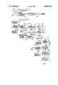
- FIG. 2is a flow chart illustrating the range identifying routine utilized by the thunderstorm sensor shown in FIG. 1.
- the thunderstorm sensor of the present invention as shown in FIG. 1includes a group of antennas, generally designated 10, for sensing the magnetic and electric fields produced by a lightning discharge.
- the antennas 10are coupled to an analog signal processor and digitizer 12 which processes the analog signal outputs of the antennas and identifies those signals that are characteristic of a cloud to ground lightning discharge.
- the signals of interest associated with a lightning discharge to groundare digitized and coupled to a microprocessor 14 which determines from the digital signals whether a thunderstorm exists within one or more ranges of the sensor.
- the microprocessortransmits information regarding thunderstorm activity to a central office or station to alert those interested in the activity.
- a pair of orthogonally positioned magnetic loop antennas 16 and 18are provided.
- the plane of the antenna 16is positioned to face, for example, in a north-south direction; whereas, the plane of the antenna 18 is positioned to face, for example, in an east-west direction. Consequently, the antenna 16 receives the north-south component of the magnetic field of any lightning discharge and the antenna 18 receives the east-west component thereof.
- the outputs of the antennas 16 and 18, which are proportional to the time derivative of the received magnetic field signals,are coupled to the analog signal processor and digitizer 12 which integrates the antenna signals to provide signals representative of the north-south and east-west field components themselves.
- the electric field of a lightning dischargeis sensed by an omnidirectional electric field antenna 20.
- the output of the antenna 20represents the time derivative of the sensed electric field.
- This signalis coupled to the analog signal processor and digitizer 12 which integrates the signal from the antenna 20 to provide a signal representative of the electric field itself.
- the analog signal processor and digitizer 12integrates and filters the signals from the antennas 16, 18 and 20 and from the integrated signals identifies those associated with a cloud to ground lightning discharge as shown in greater detail in U.S. Pat. No. 4,115,732 and U.S. Pat. No. 4,198,599, incorporated herein by reference.
- the analog signal processor and digitizer 12samples the analog north-south and east-west magnetic field component signals at their first peak values and converts the peak field values to digital representations thereof for use by the microprocessor control 14.
- the analog signal processor and digitizer 12also samples the analog electric field signal at the radiation peak and at a time subsequent thereto wherein the value of the electric field sampled at that subsequent time is representative of the electrostatic field change.
- the second electric field valuemay be sampled at some time between 50 microseconds and 1 millisecond after the radiation peak is detected and preferably about 160 microseconds after the peak.
- the two sampled electric field valuesare then converted by the analog signal processor and digitizer 12 to digital representations thereof for use by the microprocessor control 14.
- the microprocessor control 14is responsive to the digital representations of the north-south and east-west peak magnetic field components and to the sampled electric field values to determine the range of the thunderstorm activity represented by the lightning discharge to ground field signals. More particularly, and as discussed in detail below, the microprocessor control 14 calculates the amplitude of the peak radiated magnetic field from the peak north-south and east-west radiated magnetic field components. The microprocessor control 14 further calculates the ratio of the second sampled electric field value to the peak radiated electric field value to provide the relative electric field change, REFC.
- the microprocessor control 14determines whether a thunderstorm exists in a first range of the sensor, such as within zero to three nautical miles of the sensor; whether a thunderstorm exists in a second range of the sensor, such as within three to ten nautical miles of the sensor; and if the thunderstorm activity appears to be outside of the second range, the control 14 calculates the mean range of the thunderstorm activity from the magnetic field data associated with a number of lightning discharges to ground occurring within the same sector and within a predetermined time of each other.
- the microprocessor control 14preferably determines the range of thunderstorm activity from the magnetic and electric field data for the first stroke of a flash detected by the sensor although data associated with subsequent strokes may also be utilized.
- the microprocessor 14, at block 22,first determines whether a signal is too large in amplitude to be processed and if so, at block 24, the microprocessor control determines that a thunderstorm exists in the first range, i.e., within zero to three nautical miles of the sensor. If the signal can be processed, the microprocessor 14, at block 26, calculates the signal amplitude of the radiated magnetic field from the north-south and east-west components thereof. More particularly, the signal amplitude is determined from the square root of the sum of the squares of the radiated magnetic field components.
- the microprocessor 14calculates the relative electric field change from the ratio of the second sampled electric field value to the peak radiated electric field value.
- the microprocessor 14, at block 30,determines the octant of a lightning discharge to ground and updates an octant flash counter.
- the octant of a lightning discharge to groundis determined from the direction of the discharge which is calculated from the arc tangent of the ratio of the magnetic field components and the sign of the electric field signal.
- the microprocessor 14also determines the existence of a thunderstorm within the first range if the signal amplitude calculated at block 26 is determined to be greater than a first value such as 1000 and if the relative electrostatic field change is greater than a second value such as 5.
- the microprocessor 14determines whether the signal amplitude calculated at block 26 is greater than 1000 and if it is, the microprocessor proceeds to block 38 to determine whether the relative electric field change is greater than 5. If the signal amplitude is greater than 1000 and the relative electric field change is greater than 5, the microprocessor 14 at block 40, determines that a thunderstorm exists in the first range. The microprocessor also determines the existence of a thunderstorm in the first range if at least one lightning discharge to ground is identified within six or more octants within a predetermined period of time and the data associated with each discharge satisfies the criteria for the second range as discussed below.
- the microprocessor control 14is responsive to both positive and negative flashes to identify a thunderstorm within a second range of the sensor, wherein a positive flash is a flash which lowers positive charge to ground and a negative flash is a flash which lowers negative charge to ground. More specifically, the microprocessor control 14 identifies a thunderstorm within the second range of the sensor, i.e., within three to ten nautical miles of the sensor, if, for a positive or negative flash, the signal amplitude is greater than 1000 and the relative electrostatic field change is greater than 0.5 or, if, for a negative flash, the signal amplitude is greater than 500 and the relative electric field change is greater than 0.5.
- the processor 14determines at block 36 that the signal amplitude is greater than 1000 but that the relative electric field change is not greater than 5, the processor proceeds from block 38 to block 42 to determine whether the relative electric field change is greater than 0.5. If the relative electric field change is greater than 0.5 as determined by the processor 14 at block 42, the processor, at block 44 determines that a thunderstorm is within the second range of the sensor. If the microprocessor 14 determines that the signal amplitude is not greater than 1000 at block 34, the processor 14 proceeds to block 46 to determine whether the flash associated with the data is a negative flash.
- the microprocessor 14determines, at block 48, whether the signal amplitude is greater than 500 and if it is, the processor 14 proceeds to block 42. If the signal amplitude for a negative flash is greater than 500 as determined at block 48 and the relative electrostatic field change is greater than 0.5 as determined at block 42, the microprocessor 14 determines that a thunderstorm exists within the second range of the sensor and indicates this at block 44.
- the microprocessor control 14proceeds to block 32 from block 44 to determine whether second range lightning has occurred within six or more octants within a predetermined period of time. If so, the microprocessor 14 at block 34 identifies a thunderstorm in the first range.
- the microprocessor 14determines the mean range of the thunderstorm and if desired, an upper and lower limit of the range. More particularly, at block 52, the average signal amplitude of the flashes occurring within a given octant within the last 15 minutes is calculated. At block 54, the microprocessor 14 calculates the mean range of the thunderstorm within the octant from a normalization factor K divided by the average amplitude calculated at block 52. At block 54, the microprocessor 14 also calculates the standard deviation of the signal strength.
- the microprocessordetermines range limits wherein the upper range limit is equal to the normalization factor, K, divided by the quantity represented by the average calculated at block 52 minus the standard deviation calculated at block 54 and wherein the lower limit is calculated from the normalization factor K divided by the sum of the average calculated at block 52 and the standard deviation calculated at block 54.
- the reference values 1000 and 5were determined experimentally to be typical values of the signal amplitude and the relative electric field change, respectively, for the first stroke of a flash occurring about three nautical miles from the sensor; whereas, the reference values of 1000, 500 and 0.5 were determined experimentally to be typical values of the signal amplitudes and the relative electric field change for the first stroke of respective positive and negative flashes occurring about ten nautical miles from the sensor. These reference values may vary depending on the type of antennas employed in the sensor as well as the calibration of the analog signal processor and digitizer 12. These reference values will also vary if the data used is associated with a stroke subsequent to the first stroke of a flash.
- the relative electric field changes REFCfor both positive and negative flashes is shown as being compared to the same value at block 42, for more precise refinements, the REFC for positive and negative flashes may be compared to different values.
- the signal amplitude calculated at block 26is preferably the amplitude of the magnetic field detected, the amplitude of the electric field may also be used in conjunction with the relative electric field change calculated at block 28 to determine the range of detected thunderstorm activity.
- the ratio representing the relative electric field changeis preferably formed from the ratio of an electric field value sampled at a time subsequent to the peak radiated electric field and the peak radiated electric field value, the ratio may also be formed from two other values indicative of the electric field wherein the magnitude of one value depends on the magnitude of the other value.
- the thunderstorm sensor of the present inventionutilizes the relative electric field change as well as the amplitude of the peak magnetic field to distinguish weak lightning discharges close to the sensor from strong lightning discharges a distance from the sensor. Because the sensor is capable of distinguishing such discharges the thunderstorm sensor can provide a more reliable identification of a thunderstorm with fewer false indications than has heretofore been possible with a single sensor.
Landscapes
- Environmental & Geological Engineering (AREA)
- Engineering & Computer Science (AREA)
- Life Sciences & Earth Sciences (AREA)
- Atmospheric Sciences (AREA)
- Biodiversity & Conservation Biology (AREA)
- Ecology (AREA)
- Environmental Sciences (AREA)
- Geophysics And Detection Of Objects (AREA)
Abstract
Description
Claims (23)
Priority Applications (1)
| Application Number | Priority Date | Filing Date | Title |
|---|---|---|---|
| US07/092,670US4806851A (en) | 1987-09-03 | 1987-09-03 | Thunderstorm sensor and method of identifying and locating thunderstorms |
Applications Claiming Priority (1)
| Application Number | Priority Date | Filing Date | Title |
|---|---|---|---|
| US07/092,670US4806851A (en) | 1987-09-03 | 1987-09-03 | Thunderstorm sensor and method of identifying and locating thunderstorms |
Publications (1)
| Publication Number | Publication Date |
|---|---|
| US4806851Atrue US4806851A (en) | 1989-02-21 |
Family
ID=22234460
Family Applications (1)
| Application Number | Title | Priority Date | Filing Date |
|---|---|---|---|
| US07/092,670Expired - LifetimeUS4806851A (en) | 1987-09-03 | 1987-09-03 | Thunderstorm sensor and method of identifying and locating thunderstorms |
Country Status (1)
| Country | Link |
|---|---|
| US (1) | US4806851A (en) |
Cited By (31)
| Publication number | Priority date | Publication date | Assignee | Title |
|---|---|---|---|---|
| US4996473A (en)* | 1986-08-18 | 1991-02-26 | Airborne Research Associates, Inc. | Microburst/windshear warning system |
| US5057848A (en)* | 1989-05-30 | 1991-10-15 | Holaday Industries, Inc. | Broadband frequency meter probe |
| US5168212A (en)* | 1991-05-03 | 1992-12-01 | Lightning Location And Protection, Inc. | Autonomous electro-optical lightning identification and ranging apparatus for, and method of, alerting humans and protecting equipment |
| US5291208A (en)* | 1992-04-30 | 1994-03-01 | Rabun Labs, Inc. | Incipient lightning detection and device protection |
| US5296842A (en)* | 1990-04-30 | 1994-03-22 | Central Lightning Protection Co., Ltd. | Thunder alarm |
| US5396220A (en)* | 1989-05-01 | 1995-03-07 | Airborne Research Laboratories, Inc. | Storm warning system |
| US5521603A (en)* | 1992-04-30 | 1996-05-28 | Rabun Labs, Inc. | Incipient lightning detection and device protection |
| WO1997005508A3 (en)* | 1995-07-26 | 1997-04-10 | Airborne Res Ass | Lightning locating system |
| US5621410A (en)* | 1992-11-05 | 1997-04-15 | New Mexico Tech Research Foundation | Remote prediction of lightning hazards |
| US5699245A (en)* | 1995-09-11 | 1997-12-16 | Bfgoodrich Flightsystems, Inc. | Distributed lightning detection system |
| US5757322A (en)* | 1995-04-03 | 1998-05-26 | Aircell, Inc. | Cellular weather information system for aircraft |
| US5959815A (en)* | 1998-03-17 | 1999-09-28 | Gateway 2000, Inc. | Method and apparatus for detecting potentially damaging electrical fields |
| US5977762A (en)* | 1997-11-26 | 1999-11-02 | Mirage Lighting Technology Ltd | Lightning detection apparatus and methodology |
| US6347549B1 (en) | 1998-07-09 | 2002-02-19 | Ryan International Corporation | Enhancement of storm location from a single moving platform |
| US6405134B1 (en) | 2000-08-30 | 2002-06-11 | Weatherdata, Inc. | Method and apparatus for predicting lightning threats based on radar and temperature data |
| US6420862B2 (en) | 2000-02-14 | 2002-07-16 | The United States Of America As Represented By The Administrator Of The National Aeronautics And Space Administration | System and method of locating lightning strikes |
| US6552521B1 (en)* | 2000-07-11 | 2003-04-22 | The United States Of America As Represented By The United States National Aeronautics And Space Administration | Single station system and method of locating lightning strikes |
| US20050073302A1 (en)* | 2003-10-07 | 2005-04-07 | Quantum Applied Science And Research, Inc. | Integrated sensor system for measuring electric and/or magnetic field vector components |
| WO2006079041A1 (en)* | 2005-01-24 | 2006-07-27 | Quasar Federal Systems, Inc. | Integrated sensor system monitoring and characterizing lightning events |
| US7084775B1 (en) | 2004-07-12 | 2006-08-01 | User-Centric Ip, L.P. | Method and system for generating and sending user-centric weather alerts |
| US20060220635A1 (en)* | 2005-01-20 | 2006-10-05 | Satoshi Kazama | Method, apparatus, and program for measuring an electromagnetic field and medium recording the program |
| WO2009115639A1 (en)* | 2008-03-20 | 2009-09-24 | Nokia Corporation | Lightning detection |
| US20090262016A1 (en)* | 2008-04-22 | 2009-10-22 | Nokia Corporation | Supporting the use of a virtual reference station |
| US20100023267A1 (en)* | 2008-07-24 | 2010-01-28 | Karabin Christopher R | Method and system for determining cloud-to-ground lightning information |
| KR100966795B1 (en)* | 2007-07-24 | 2010-06-29 | 길경석 | Lightning position expression device and method |
| US20110028956A1 (en)* | 2004-03-15 | 2011-02-03 | Amo Manufacturing Usa, Llc | Method For Stabilizing Delivered Laser Energy |
| US20110034142A1 (en)* | 2007-11-08 | 2011-02-10 | James Roland Jordan | Detection of transient signals in doppler spectra |
| US20110309973A1 (en)* | 2009-07-17 | 2011-12-22 | Codar Ocean Sensors, Ltd. | Combined transmit/receive single-post antenna for hf/vhf radar |
| EP1946127A4 (en)* | 2005-10-14 | 2014-04-23 | Nokia Corp | DETECTION OF LIGHTING |
| CN109358314A (en)* | 2018-10-19 | 2019-02-19 | 国网辽宁省电力有限公司电力科学研究院 | A device and method for locating a discharge source based on a magnetic field radio frequency signal |
| CN113484934A (en)* | 2021-06-08 | 2021-10-08 | 北京华云东方探测技术有限公司 | Method and system for determining thunderstorm observation data, electronic equipment and storage medium |
Citations (7)
| Publication number | Priority date | Publication date | Assignee | Title |
|---|---|---|---|---|
| US3715660A (en)* | 1971-12-30 | 1973-02-06 | Nasa | Determining distance to lightning strokes from a single station |
| US3754263A (en)* | 1972-01-28 | 1973-08-21 | Nasa | Lightning tracking system |
| US4023408A (en)* | 1975-01-10 | 1977-05-17 | Dytronics Company, Inc. | Stormscope |
| US4115732A (en)* | 1976-10-14 | 1978-09-19 | The University Of Arizona Foundation | Detection system for lightning |
| US4198599A (en)* | 1978-07-31 | 1980-04-15 | The University Of Arizona Foundation | Gated lightning detection system |
| US4506211A (en)* | 1981-02-17 | 1985-03-19 | Coleman Ernest W | Storm warning method and apparatus |
| US4672305A (en)* | 1983-07-22 | 1987-06-09 | Ernco Industries, Inc. | Storm warning method and apparatus |
- 1987
- 1987-09-03USUS07/092,670patent/US4806851A/ennot_activeExpired - Lifetime
Patent Citations (8)
| Publication number | Priority date | Publication date | Assignee | Title |
|---|---|---|---|---|
| US3715660A (en)* | 1971-12-30 | 1973-02-06 | Nasa | Determining distance to lightning strokes from a single station |
| US3754263A (en)* | 1972-01-28 | 1973-08-21 | Nasa | Lightning tracking system |
| US4023408A (en)* | 1975-01-10 | 1977-05-17 | Dytronics Company, Inc. | Stormscope |
| US4115732A (en)* | 1976-10-14 | 1978-09-19 | The University Of Arizona Foundation | Detection system for lightning |
| US4115732B1 (en)* | 1976-10-14 | 1986-12-30 | ||
| US4198599A (en)* | 1978-07-31 | 1980-04-15 | The University Of Arizona Foundation | Gated lightning detection system |
| US4506211A (en)* | 1981-02-17 | 1985-03-19 | Coleman Ernest W | Storm warning method and apparatus |
| US4672305A (en)* | 1983-07-22 | 1987-06-09 | Ernco Industries, Inc. | Storm warning method and apparatus |
Cited By (47)
| Publication number | Priority date | Publication date | Assignee | Title |
|---|---|---|---|---|
| US4996473A (en)* | 1986-08-18 | 1991-02-26 | Airborne Research Associates, Inc. | Microburst/windshear warning system |
| US5396220A (en)* | 1989-05-01 | 1995-03-07 | Airborne Research Laboratories, Inc. | Storm warning system |
| US5057848A (en)* | 1989-05-30 | 1991-10-15 | Holaday Industries, Inc. | Broadband frequency meter probe |
| US5296842A (en)* | 1990-04-30 | 1994-03-22 | Central Lightning Protection Co., Ltd. | Thunder alarm |
| US5168212A (en)* | 1991-05-03 | 1992-12-01 | Lightning Location And Protection, Inc. | Autonomous electro-optical lightning identification and ranging apparatus for, and method of, alerting humans and protecting equipment |
| US5521603A (en)* | 1992-04-30 | 1996-05-28 | Rabun Labs, Inc. | Incipient lightning detection and device protection |
| US5291208A (en)* | 1992-04-30 | 1994-03-01 | Rabun Labs, Inc. | Incipient lightning detection and device protection |
| US5621410A (en)* | 1992-11-05 | 1997-04-15 | New Mexico Tech Research Foundation | Remote prediction of lightning hazards |
| US5757322A (en)* | 1995-04-03 | 1998-05-26 | Aircell, Inc. | Cellular weather information system for aircraft |
| US6246367B1 (en) | 1995-07-26 | 2001-06-12 | Airborne Research Associates, Inc. | Lightning locating system |
| WO1997005508A3 (en)* | 1995-07-26 | 1997-04-10 | Airborne Res Ass | Lightning locating system |
| US5771020A (en)* | 1995-07-26 | 1998-06-23 | Airborne Research Associates, Inc. | Lightning locating system |
| US5699245A (en)* | 1995-09-11 | 1997-12-16 | Bfgoodrich Flightsystems, Inc. | Distributed lightning detection system |
| US5977762A (en)* | 1997-11-26 | 1999-11-02 | Mirage Lighting Technology Ltd | Lightning detection apparatus and methodology |
| US5959815A (en)* | 1998-03-17 | 1999-09-28 | Gateway 2000, Inc. | Method and apparatus for detecting potentially damaging electrical fields |
| US6347549B1 (en) | 1998-07-09 | 2002-02-19 | Ryan International Corporation | Enhancement of storm location from a single moving platform |
| US6420862B2 (en) | 2000-02-14 | 2002-07-16 | The United States Of America As Represented By The Administrator Of The National Aeronautics And Space Administration | System and method of locating lightning strikes |
| US6552521B1 (en)* | 2000-07-11 | 2003-04-22 | The United States Of America As Represented By The United States National Aeronautics And Space Administration | Single station system and method of locating lightning strikes |
| US6405134B1 (en) | 2000-08-30 | 2002-06-11 | Weatherdata, Inc. | Method and apparatus for predicting lightning threats based on radar and temperature data |
| US20050073302A1 (en)* | 2003-10-07 | 2005-04-07 | Quantum Applied Science And Research, Inc. | Integrated sensor system for measuring electric and/or magnetic field vector components |
| US20050073322A1 (en)* | 2003-10-07 | 2005-04-07 | Quantum Applied Science And Research, Inc. | Sensor system for measurement of one or more vector components of an electric field |
| US20070159167A1 (en)* | 2003-10-07 | 2007-07-12 | Hibbs Andrew D | Integrated sensor system for measuring electric and/or magnetic field vector components |
| US7141968B2 (en) | 2003-10-07 | 2006-11-28 | Quasar Federal Systems, Inc. | Integrated sensor system for measuring electric and/or magnetic field vector components |
| US7141987B2 (en) | 2003-10-07 | 2006-11-28 | Quantum Applied Science And Research, Inc. | Sensor system for measurement of one or more vector components of an electric field |
| US8187259B2 (en) | 2004-03-15 | 2012-05-29 | Amo Manufacturing Usa, Llc. | System and method for stabilizing delivered laser energy |
| US20110028956A1 (en)* | 2004-03-15 | 2011-02-03 | Amo Manufacturing Usa, Llc | Method For Stabilizing Delivered Laser Energy |
| US7084775B1 (en) | 2004-07-12 | 2006-08-01 | User-Centric Ip, L.P. | Method and system for generating and sending user-centric weather alerts |
| US20060267783A1 (en)* | 2004-07-12 | 2006-11-30 | User-Centric Ip, L.P. | Method and system for generating and sending user-centric weather alerts |
| US7358749B2 (en)* | 2005-01-20 | 2008-04-15 | Taiyo Yuden, Co., Ltd. | Method, apparatus, and program for measuring an electromagnetic field and medium storing the program |
| US20060220635A1 (en)* | 2005-01-20 | 2006-10-05 | Satoshi Kazama | Method, apparatus, and program for measuring an electromagnetic field and medium recording the program |
| US20080122424A1 (en)* | 2005-01-24 | 2008-05-29 | Yongming Zhang | Integrated Sensor System Monitoring and Characterizing Lightning Events |
| WO2006079041A1 (en)* | 2005-01-24 | 2006-07-27 | Quasar Federal Systems, Inc. | Integrated sensor system monitoring and characterizing lightning events |
| EP1946127A4 (en)* | 2005-10-14 | 2014-04-23 | Nokia Corp | DETECTION OF LIGHTING |
| KR100966795B1 (en)* | 2007-07-24 | 2010-06-29 | 길경석 | Lightning position expression device and method |
| US8022864B2 (en)* | 2007-11-08 | 2011-09-20 | The United States Of America As Represented By The Secretary Of Commerce | Detection of transient signals in doppler spectra |
| US20110034142A1 (en)* | 2007-11-08 | 2011-02-10 | James Roland Jordan | Detection of transient signals in doppler spectra |
| WO2009115639A1 (en)* | 2008-03-20 | 2009-09-24 | Nokia Corporation | Lightning detection |
| JP2014066715A (en)* | 2008-04-22 | 2014-04-17 | Nokia Corp | Supporting of use of virtual reference station |
| US8078192B2 (en) | 2008-04-22 | 2011-12-13 | Nokia Corporation | Supporting the use of a virtual reference station |
| US20090262016A1 (en)* | 2008-04-22 | 2009-10-22 | Nokia Corporation | Supporting the use of a virtual reference station |
| US7957902B2 (en) | 2008-07-24 | 2011-06-07 | The United States Of America As Represented By The Secretary Of The Navy | Method and system for determining cloud-to-ground lightning information |
| US20100023267A1 (en)* | 2008-07-24 | 2010-01-28 | Karabin Christopher R | Method and system for determining cloud-to-ground lightning information |
| US20110309973A1 (en)* | 2009-07-17 | 2011-12-22 | Codar Ocean Sensors, Ltd. | Combined transmit/receive single-post antenna for hf/vhf radar |
| US8477065B2 (en)* | 2009-07-17 | 2013-07-02 | Codar Ocean Sensors Ltd | Combined transmit/receive single-post antenna for HF/VHF radar |
| CN109358314A (en)* | 2018-10-19 | 2019-02-19 | 国网辽宁省电力有限公司电力科学研究院 | A device and method for locating a discharge source based on a magnetic field radio frequency signal |
| CN113484934A (en)* | 2021-06-08 | 2021-10-08 | 北京华云东方探测技术有限公司 | Method and system for determining thunderstorm observation data, electronic equipment and storage medium |
| CN113484934B (en)* | 2021-06-08 | 2023-12-29 | 北京华云东方探测技术有限公司 | Determination method and system for thunderstorm observation data, electronic equipment and storage medium |
Similar Documents
| Publication | Publication Date | Title |
|---|---|---|
| US4806851A (en) | Thunderstorm sensor and method of identifying and locating thunderstorms | |
| US4672305A (en) | Storm warning method and apparatus | |
| US4198599A (en) | Gated lightning detection system | |
| US5057820A (en) | Optical warning system | |
| US5218360A (en) | Millimeter-wave aircraft landing and taxing system | |
| EP0161940B1 (en) | Radio direction finding for locating lightening ground strikes | |
| US6246367B1 (en) | Lightning locating system | |
| CA1118520A (en) | Lightning detection system utilizing triangulation and field amplitude comparison techniques | |
| US5245274A (en) | Storm monitor | |
| US20070239326A1 (en) | Systems and methods for monitoring an altitude in a flight vehicle | |
| US4506211A (en) | Storm warning method and apparatus | |
| GB1515447A (en) | Intruder detection system | |
| US5528494A (en) | Statistically based thunderstorm cell detection and mapping system | |
| CN108845188A (en) | A kind of mono-station location method and system of remote cloud-to-ground flash | |
| CN110850483A (en) | Underwater target detection and positioning method based on electric field electrode array arrangement | |
| EP3889927A1 (en) | System and method for presence detection in an environment to be monitored | |
| US6133990A (en) | Method for determining presence and distribution of clouds | |
| CN109856608A (en) | A kind of high confidence rate detection method of radar target based on recurrence clutter map | |
| US4864282A (en) | Method and apparatus for detecting or measuring the presence of humans or biological organism | |
| EP0706060B1 (en) | Thunderstorm cell detection and mapping system | |
| US2953020A (en) | Meteorological apparatus | |
| CN116311775A (en) | Wearable near-electricity alarm equipment and monitoring system | |
| WO1991000525A1 (en) | Electric field detection system | |
| WO2000002060A1 (en) | Method and system for passively determining the altitude of an object | |
| CN114399904A (en) | Lane recognition method for automatically recognizing lane by radar |
Legal Events
| Date | Code | Title | Description |
|---|---|---|---|
| AS | Assignment | Owner name:LIGHTING LOCATION AND PROTECTION, INC., 1001 SOUTH Free format text:ASSIGNMENT OF ASSIGNORS INTEREST.;ASSIGNORS:PIFER, ALBURT E.;BYERLEY, LEON G.;KRIDER, E. PHILIP;REEL/FRAME:004777/0294 Effective date:19871026 Owner name:LIGHTING LOCATION AND PROTECTION, INC., A CORP. OF Free format text:ASSIGNMENT OF ASSIGNORS INTEREST;ASSIGNORS:PIFER, ALBURT E.;BYERLEY, LEON G.;KRIDER, E. PHILIP;REEL/FRAME:004777/0294 Effective date:19871026 | |
| STCF | Information on status: patent grant | Free format text:PATENTED CASE | |
| FEPP | Fee payment procedure | Free format text:PAYOR NUMBER ASSIGNED (ORIGINAL EVENT CODE: ASPN); ENTITY STATUS OF PATENT OWNER: LARGE ENTITY | |
| FPAY | Fee payment | Year of fee payment:4 | |
| AS | Assignment | Owner name:GLOBAL ATMOSPHERICS, INC., ARIZONA Free format text:ASSIGNMENT OF ASSIGNORS INTEREST;ASSIGNOR:LIGHTNING LOCATION AND PROTECTION, INC., A AZ CORP.;REEL/FRAME:007439/0378 Effective date:19950224 | |
| FPAY | Fee payment | Year of fee payment:8 | |
| AS | Assignment | Owner name:BANK ONE, ARIZONA, NA, ARIZONA Free format text:SECURITY AGREEMENT;ASSIGNOR:GLOBAL ATMOSPHERICS, INC.;REEL/FRAME:010371/0708 Effective date:19990719 | |
| REMI | Maintenance fee reminder mailed | ||
| FPAY | Fee payment | Year of fee payment:12 | |
| SULP | Surcharge for late payment | Year of fee payment:11 | |
| AS | Assignment | Owner name:BANK ONE, ARIZONA, NA, ARIZONA Free format text:SECURITY AGREEMENT;ASSIGNOR:GLOBAL ATMOSPHERICS;REEL/FRAME:012428/0465 Effective date:20010822 |