US4806833A - System for conditioning air, method of operating such, and circuit - Google Patents
System for conditioning air, method of operating such, and circuitDownload PDFInfo
- Publication number
- US4806833A US4806833AUS06/909,547US90954786AUS4806833AUS 4806833 AUS4806833 AUS 4806833AUS 90954786 AUS90954786 AUS 90954786AUS 4806833 AUS4806833 AUS 4806833A
- Authority
- US
- United States
- Prior art keywords
- speed
- static pressure
- blower
- blower means
- preselected
- Prior art date
- Legal status (The legal status is an assumption and is not a legal conclusion. Google has not performed a legal analysis and makes no representation as to the accuracy of the status listed.)
- Expired - Fee Related
Links
- 238000000034methodMethods0.000titleclaimsabstractdescription31
- 230000003750conditioning effectEffects0.000titleclaimsabstractdescription20
- 230000003068static effectEffects0.000claimsabstractdescription129
- 230000001143conditioned effectEffects0.000claimsabstractdescription43
- 230000000694effectsEffects0.000claimsabstractdescription32
- 230000004075alterationEffects0.000claimsabstractdescription27
- 230000004044responseEffects0.000claimsabstractdescription19
- 238000004804windingMethods0.000claimsdescription25
- 241000555745SciuridaeSpecies0.000claimsdescription24
- 230000001105regulatory effectEffects0.000claimsdescription8
- 230000001276controlling effectEffects0.000claimsdescription7
- 230000008878couplingEffects0.000claimsdescription7
- 238000010168coupling processMethods0.000claimsdescription7
- 238000005859coupling reactionMethods0.000claimsdescription7
- 230000005291magnetic effectEffects0.000claimsdescription4
- 238000006243chemical reactionMethods0.000description15
- 239000003990capacitorSubstances0.000description9
- 230000003287optical effectEffects0.000description9
- 230000008859changeEffects0.000description3
- 238000001816coolingMethods0.000description3
- 238000010438heat treatmentMethods0.000description3
- 238000004378air conditioningMethods0.000description2
- 230000003247decreasing effectEffects0.000description2
- 238000010586diagramMethods0.000description2
- 238000013022ventingMethods0.000description2
- 239000000654additiveSubstances0.000description1
- 230000000996additive effectEffects0.000description1
- 230000033228biological regulationEffects0.000description1
- 238000010276constructionMethods0.000description1
- 238000013461designMethods0.000description1
- 239000003302ferromagnetic materialSubstances0.000description1
- 230000002401inhibitory effectEffects0.000description1
- 230000000670limiting effectEffects0.000description1
- 239000000463materialSubstances0.000description1
- 238000012544monitoring processMethods0.000description1
- 238000011017operating methodMethods0.000description1
- 230000009467reductionEffects0.000description1
- 230000002829reductive effectEffects0.000description1
- 238000012546transferMethods0.000description1
- 238000009966trimmingMethods0.000description1
- 210000003462veinAnatomy0.000description1
Images


Classifications
- G—PHYSICS
- G05—CONTROLLING; REGULATING
- G05D—SYSTEMS FOR CONTROLLING OR REGULATING NON-ELECTRIC VARIABLES
- G05D7/00—Control of flow
- G05D7/06—Control of flow characterised by the use of electric means
- G05D7/0617—Control of flow characterised by the use of electric means specially adapted for fluid materials
- G05D7/0629—Control of flow characterised by the use of electric means specially adapted for fluid materials characterised by the type of regulator means
- G05D7/0676—Control of flow characterised by the use of electric means specially adapted for fluid materials characterised by the type of regulator means by action on flow sources
- F—MECHANICAL ENGINEERING; LIGHTING; HEATING; WEAPONS; BLASTING
- F04—POSITIVE - DISPLACEMENT MACHINES FOR LIQUIDS; PUMPS FOR LIQUIDS OR ELASTIC FLUIDS
- F04D—NON-POSITIVE-DISPLACEMENT PUMPS
- F04D27/00—Control, e.g. regulation, of pumps, pumping installations or pumping systems specially adapted for elastic fluids
- F04D27/004—Control, e.g. regulation, of pumps, pumping installations or pumping systems specially adapted for elastic fluids by varying driving speed
- F—MECHANICAL ENGINEERING; LIGHTING; HEATING; WEAPONS; BLASTING
- F24—HEATING; RANGES; VENTILATING
- F24F—AIR-CONDITIONING; AIR-HUMIDIFICATION; VENTILATION; USE OF AIR CURRENTS FOR SCREENING
- F24F11/00—Control or safety arrangements
- F24F11/70—Control systems characterised by their outputs; Constructional details thereof
- F24F11/72—Control systems characterised by their outputs; Constructional details thereof for controlling the supply of treated air, e.g. its pressure
- Y—GENERAL TAGGING OF NEW TECHNOLOGICAL DEVELOPMENTS; GENERAL TAGGING OF CROSS-SECTIONAL TECHNOLOGIES SPANNING OVER SEVERAL SECTIONS OF THE IPC; TECHNICAL SUBJECTS COVERED BY FORMER USPC CROSS-REFERENCE ART COLLECTIONS [XRACs] AND DIGESTS
- Y02—TECHNOLOGIES OR APPLICATIONS FOR MITIGATION OR ADAPTATION AGAINST CLIMATE CHANGE
- Y02B—CLIMATE CHANGE MITIGATION TECHNOLOGIES RELATED TO BUILDINGS, e.g. HOUSING, HOUSE APPLIANCES OR RELATED END-USER APPLICATIONS
- Y02B30/00—Energy efficient heating, ventilation or air conditioning [HVAC]
- Y02B30/70—Efficient control or regulation technologies, e.g. for control of refrigerant flow, motor or heating
Definitions
- This inventionrelates in general to systems for conditioning the temperature of a space and in particular to a system for conditioning air and for maintaining a preselected flow rate of the conditioned air through at least a part of the system regardless of the static pressure therein, a method of operating a system for conditioning air, and a circuit.
- a systemfor conditioning air and for maintaining a preselected flow rate of the conditioned air through a contained space with respect to the static pressure therein.
- the systemhas blower means rotatable at a speed against an existing static pressure in the contained space for establishing the preselected flow rate therethrough of the conditioned air.
- Meansis provided for varying the static pressure in the contained space, and the blower means is responsive only to the static pressure variation to effect an alteration in the speed of the blower means in following relation with the static pressure variation.
- a variable speed dynamoelectric machineis energized to rotatably drive the blower means, and means is associated with the dynamoelectric machine for sensing the speed alteration of the blower means.
- Control meansis operable generally for regulating the energization of the dynamoelectric machine, and the control means is responsive to the sensing means to adjust the energization of the dynamoelectric machine in following relation with the sensed speed alteration so as to reestablish the preselected flow rate of the conditioned air through the contained space at the varied static pressure acting on the blower means driven by the dynamoelectric machine.
- a methodfor operating a system for conditioning air.
- the systemhas a static pressure adapted to be varied and includes a variable speed blower means rotatably operable for flowing the conditioned air through at least a part of the system.
- the speed of the blower meansis set to effect a preselected flow rate of the conditioned air through the at least part of the system at an existing static pressure therein, and the speed of the blower means is altered only in response to a variation in the static pressure and only in following relation with the static pressure variation.
- the alteration in the speed of the blower meansis sensed, and in response to the sensed speed alteration, the speed of the blower means is adjusted in following relation with the static pressure variation so as to establish the preselected flow rate of the conditioned air through the at least part of the system at the varied static pressure.
- a circuit in one form of the inventionfor controlling a dynamoelectric machine associated in driving relation with a blower in an air handling system, and the circuit provides control of blower speed over a range of static pressure variations to maintain relatively constant air flow in the system.
- the circuithas a power switching circuit operable generally to supply power to the dynamoelectric machine to effect the drive of the blower, and the power supplied to the dynamoelectric machine is proportional to an operating speed thereof.
- Regulatormeans responsive to a signal representative of a preselected operating speed of the dynamoelectric machine and a signal representative of the power supplied to the dynamoelectric machine for controlling the operation of the power switching circuit.
- Tachometer meansis operable generally for sensing the operating speed of the dynamoelectric machine and for providing a signal representative thereof to the regulator means, and means is associated with the regulator means for summing the tachometer means signal with the preselected operating speed signal to vary the operating speed of the dynamoelectric machine in following relation with the static pressure variations in the system so as to maintain the relatively constant air flow therein.
- FIG. 1is a schematic view showing a typical system for conditioning air built in accordance with the preferred embodiment of the invention, respectively, and illustrating principles which may be practiced in a method of operating the system also in one form of the invention;
- FIG. 2is an exploded perspective view of a typical variable speed dynamoelectric machine which may be utilized to rotatably drive a blower means in the system of FIG. 1;
- FIG. 3is a schematic view showing a multi-stage winding arrangement for the dynamoelectric machine of FIG. 2;
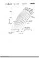
- FIG. 4is a graphical representation of the CFM flowed at various static pressures in the system of FIG. 1 with the CFM being a function of the speed and torque of a typical blower means;
- FIG. 5is a block diagram of a circuit in one form of the invention for controlling the energization of the dynamoelectric machine of FIG. 2 in the apparatus of FIG. 1;
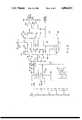
- FIG. 6is a schematic diagram showing the essential elements of some of the circuitry shown in FIG. 5.
- System 11has a static pressure adapted to be varied, and the system includes a variable speed blower or blower means 13 rotatably operable for flowing the conditioned air through at least a part of the system, such as for instance, a contained space or the like indicated generally at 15 (FIGS. 1 and 4-6).
- the speed of the bloweris set to effect a preselected flowrate of the conditioned air through the at least part of the system part or contained space 15 at an existing static pressure therein, and the speed of the blower is altered only in response to a variation in the static pressure and in direct or following relation with the static pressure variation (FIGS. 4-6).
- the alteration in the speed of blower 13is sensed, and in response to the sensed speed alteration, the speed of the blower is adjusted to effect a variation in the flow rate in direct or following relation with the static pressure variation so as to establish the preselected flow rate of the conditioned air through contained space 15 at the varied static pressure (FIGS. 1 and 4-6).
- a variable speed dynamoelectric machinesuch as for instance an electronically commutated motor 17 (hereinafter sometimes referred to as an ECM)
- ECMelectronically commutated motor 17
- a stationary assembly 19which includes a core or stator 21 of suitable ferromagnetic material
- a multistage winding arrangement 23is associated with the stationary assembly having a plurality of winding stages 25A, 25B, 25C, as best seen in FIG. 3, with at least some of the winding stages being adapted to be electronically commutated in at least one preselected sequence, as discussed in greater detail hereinafter.
- a rotatable assembly 27 of ECM 17is rotatably associated with stationary assembly 19 and comprises a permanent magnet rotor or rotor means 29 operable generally for rotatably driving blower 13 and associated in selective magnetic coupling relation with winding stages 25A, 25B, 25C so as to be rotatably driven by the winding stages upon the electronic commutation thereof.
- Permanent magnet rotor means 29includes a plurality of magnet material elements 31 secured to a rotor 33 generally about the circumference thereof, and the rotor is secured about a shaft 35.
- rotor shaft 35may be journaled by suitable bearing means in a pair of opposite end frames forming a part of stationary assembly 19 of ECM 17, and the rotor shaft is, of course, adapted to be coupled in rotatable driving relation with blower 13.
- ECM 17is illustrated herein as having three winding stages 25A, 25B, 25C, it is contemplated that an ECM having any convenient number of winding stages greater than one may be employed within the scope of the invention so as to meet at least some of the objects thereof. If a more detailed discussion of the construction and operation of an ECM, such as that indicated herein at 17, is desired, reference may be had to U.S. Pat. No.
- blower 13is illustrated and discussed herein as rotatably driving blower 13 for convenience of disclosure, it is contemplated that various other electric motors of the variable speed type may be utilized to rotatably drive the blower within the scope of the invention so as to meet at least some of the objects thereof. Additionally, blower 13 as illustrated and discussed herein is of the squirrel cage type as well known in the art.
- the only preliminary step necessary in the practice of the operating method of this inventionis to choose or preselect the flow rate desired for the flow of the conditioned air through contained space 15 of system 11 regardless of the static pressure therein.
- at least some of winding stages 25A, 25B, 25C of ECM 17may be electronically commutated in the aforementioned at least one preselected sequence, and current at least generally at a preselected value may be supplied to such winding stages upon the electronic commutation thereof.
- Permanent magnet rotor means 29is associated in selective magnetic coupling relation with winding stages 25A, 25B, 25C of ECM 17, and upon the electronic commutation of at least some of the winding stages, the permanent magnet rotor means and blower 13 are conjointly rotated.
- the supply of current at the preselected value thereof to ECM 17 to effect its energizationsets or establishes the speed at which permanent magnet rotor means 29 of the ECM and blower 13 are rotated against the then existing static pressure in contained space 15 of system 11.
- the existing static pressure in contained space 15reacts against the rotation of blower 13 so as to establish the preselected flow rate of the conditioned air through the contained space at the existing static pressure therein.
- the static pressure in contained space 15may be varied or changed by the opening, closing or merely adjusting a means, such as for instance a register or vent 37 or the like, for venting the contained space as well known to the art.
- a meanssuch as for instance a register or vent 37 or the like, for venting the contained space as well known to the art.
- a sensor or sensing meanssuch as for instance a tachometer 39 or the like is associated with ECM 17 and measures or senses the speed of permanent magnet rotor means 29 in its driving relation with blower 13. Therefore, since blower 13 and permanent magnet rotor means 29 are drivingly coupled, the rotational speed of the permanent magnet rotor means sensed by tachometer 39 upon the energization of ECM 17 is the same as that of the blower.
- tachometer 39is operable to effect an adjustment in the current supplied to winding stages 25A, 25B, 25C, as discussed in greater detail hereinafter, upon the electronic commutation of at least some of the winding stages.
- system 11in one form of the invention is provided for conditioning air and for maintaining the preselected flow rate of the conditioned air through contained space 15 with respect to the static pressure therein (FIG. 1).
- blower 13is rotatable at a speed against the existing static pressure in contained space 15 for establishing the preselected flow rate therethrough (FIGS. 1 and 4-6).
- Vent or venting means 37is operable for varying the static pressure in contained space 15, and blower 13 is responsive to only the static pressure variation to effect the alteration in the speed of the blower in following relation with the static pressure variation (FIGS. 1 and 4).
- ECM 17is energized to rotatably drive blower 13, and tachometer 39 is associated with the ECM for sensing the speed alteration of the blower (FIGS. 1, 2, 5 and 6).
- Control meanssuch as of instance a pulse width modulating circuit 41 or the like, is operable generally for regulating the energization of ECM 17, and the control means is responsive to tachometer 39 to adjust the energization of the ECM in following relation with the sensed speed alteration of blower 13 thereby to reestablish the preselected flow rate of the conditioned air through contained space 15 at the varied static pressure acting on the blower rotatably driven by the ECM (FIGS. 1, 5 and 6).
- air handling system 11includes an apparatus 43 for conditioning the temperature of the air flowed in the system and also a circuit 45 in one form of the invention for controlling the operation of the apparatus to maintain the preselected flow rate of the conditioned air in the system.
- System 11has suitable ductwork 47 defining contained space 15 through which the conditioned air is flowed from apparatus 43 through vent 37 into a room or space in a building (not shown).
- Apparatus 43includes blower 13 and ECM 17, and a housing or casing 49 for the blower is associated with system ductwork 47 so as to define therewith contained space 15.
- a heat exchanger 51 of apparatus 43is disposed within contained space 15 of system 11, and blower 13 effects the passage of air through the system in heat exchange relation with the heat exchanger.
- Heat exchanger 51is connected at 53 to suitable means, such as for instance a fire box of a furnace or the like (not shown), for providing a heating medium to the heat exchanger which is in heat exchange relation with the air being passed over it, as previously mentioned, and the heat exchanger is also connected at 55 to suitable means, such as for instance a flue or the like (not shown) for distributing or delivering the heating medium from the heat exchanger.
- apparatus 43is illustrated herein as a furnace, it is contemplated that other apparatus, such as a central air conditioning unit, a heat pump unit or an automotive air conditioner unit or the like for instance, may be utilized within the scope of the invention so as to meet at least some of the objects thereof.
- control input parametersare supplied through an input means 57 which establishes a preselected desired air flow rate as a function of the thermal output of a heating or cooling apparatus (not shown).
- means 57comprises a microcomputer having programmed therein a predetermined relationship between thermal capability and air flow.
- the means 57would be connected to provide control signals to a compressor for controlling the speed thereof to thereby establish a desired thermal capability.
- Means 57would then provide an air flow value signal preselected to establish the most efficient transfer of thermal energy from the cooling apparatus into system 11.
- the control input parameters to system 11may be either analogue or digital values.
- the control input parameterswere selected to be input to system 11 in a digital form.
- the digital formmerely comprises a pulse width modulated signal operating at a predetermined pulse repetition rate suitable for coupling through an optical isolator 59.
- Optical isolator 59is of a type well known in the art generally comprising a light emitting diode and a photoresponsive transistor positioned adjacent to the diode which can be switched on and off by light emitted by the diode. Such optical isolators are commercially available devices produced by myriad electronic manufacturers.
- Optical isolator 59merely isolates the electrical voltage levels appearing in circuit 45 from the input control means 41.
- the pulse width modulated signal passed through optical isolator 59has a time ratio of on time to off time varying between 100% and 0%.
- width modulated signal in current regulating circuit 45 for ECM 17it is desirable to convert the pulse width modulated signal to a suitable average voltage level representative of the desired speed of blower 13. This conversion is effected in a duty cycle conversion to voltage circuit 61.
- conversion circuit 61has two additional input lines 63, 65.
- Input line 63is connected to a voltage reference source 67 which provides a maximum voltage reference setting for ECM 17.
- Input line 65is connected to a reference voltage source 69 which provides a minimum voltage reference setting for ECM 17.
- Voltage reference sources 67, 69represent settings which can be adjusted to establish a minimum and maximum value o the flow rate for the conditioned air depending upon the use of system 11. If system 11 is being operated at some value less than its maximum capability, the control input parameters established by input means 57 set the appropriate percentage of the maximum capability of the system. In an exemplary system, the lowest minimum value which might be set by adjustment of voltage reference source 69 could be in the range of 400 cubic feet per minute (CFM) of airflow, and the maximum value which might be set by adjustment of voltage reference source 67 could be approximately 1,000 CFM.
- CFMcubic feet per minute
- input means 57could provide a reference pulse modulated signal which would reduce the system performance from its maximum 1,000 CFM to some value between the minimum and maximum values.
- the conversion circuit 61might be set to provide system airflow of 700 CFM.
- the operation of conversion circuit 61is to switch between the maximum setting of input line 63 and the minimum setting of input line 65 at a rate proportional to the pulse width modulated rate coupled through optical isolator 61.
- the signals obtained from input lines 63, 65are then averaged to obtain a voltage reference proportional to the time ratio of the pulse width modulated signal.
- the voltage reference provided by conversion circuit 61is coupled to a pulse width modulated regulate circuit or regulator 71 (sometimes hereinafter referred to as a PWM regulator) which uses the voltage reference to regulate the current supplied to a plurality of high voltage switching devices (not shown) located in a power module 73.
- PWM regulator 71monitors the current supply to power module 73 by monitoring the voltage developed across a current shunt resistance 75.
- PWM regulator 71uses the reference voltage supplied by conversion circuit 61 to set a peak value for current through shunt 75.
- the switching devices in power module 73are gated into conduction at predetermined times, and the length of time that the switching devices remain in conduction is determined by PWM regulator 71.
- a switching device in power module 73is gated into conduction allowing current through shunt 75 to build up to a point at which it reaches or exceeds the reference value supplied from conversion circuit 61.
- PWM regulator 71provides a signal to a gate array circuit 77 to effect a turn off of the conducting switching device in power module 73.
- Gate array 77may be a microprocessor based drive circuit for providing control signals to the switching devices in power module 73.
- Gate array 77also provides a signal indicating each time that a switching device is commutated or gated into conduction in power module 73, and such pulses are representative of the speed of ECM 17 since, as is well known in the art, the rotational speed of the ECM is controlled by the gating of the switching devices in power module 73.
- the commutation pulsesmay be coupled through another optical isolator 79 to input means 57 for providing a readout of the speed of blower 13.
- Circuit 45includes an AC to DC power converter 81 which converts incoming alternating current power to direct current power for use by the circuitry powering ECM 17.
- Converter 81may be any of a number of well known types of converters, such as for example a full wave bridge diode rectifier circuit or the like.
- a thermal protection device 83 of a type well known to the artmay be associated with ECM 17 to cause the power to be removed therefrom in the event of the occurrence of an overheat condition, and the thermal protection device is generally connected to provide a signal to gate array 77 for inhibiting power to ECM 17 in the event of the occurrence of the overheat condition.
- a reset device 85 of a type well known in the artis operable to sense that thermal protection device 83 has cooled and reset, and the reset device couples a reset signal to gate array 77 to allow the restarting of ECM 17.
- Such reset devicesare also well known in the art.
- Tachometer 39senses the increase in speed of blower 13 and ECM 17 and provides an additional signal to PWM regulator 71 for causing an increase in the torque of the ECM and blower by adding an additional signal to the reference voltage provided by conversion circuit 61. Accordingly, the system 11 operates with a positive torque loop so that any increase in the speed of blower 13 and ECM 17 is accompanied by a positive torque increase which causes a still further increase in the speed of ECM 17. From the above description, it will be apparent that the disclosed ECM control system operates as an open loop system for causing an increase in ECM torque to thereby vary speed in correspondence with the curves illustrated in FIG. 4 to maintain a desired CFM.
- Tachometer 39comprises a one shot or monostable multi-vibrator 87 of a type well known in the art.
- multi-vibrator 87may be a type 4047 available from Texas Instruments Inc. of Dallas, Tex.
- Multi-vibrator 87includes an external capacitor CT and an external variable resistor RST, which resistor RST can be adjusted to set the time duration of a pulse generated by the multi-vibrator.
- multi-vibrator 87Upon receipt of a commutate pulse (COMM PULSE) from gate array 77, multi-vibrator 87 generates a pulse having a preselected time duration, which pulse is coupled through an RC filter comprising a first resistor 89, a second resistor 91 and a capacitor 93. Capacitor 93 is connected between a junction intermediate resistors 89, 91 and a common or reference ground terminal. Resistor 89 and capacitor 93 serve to average the pulses from multi-vibrator 87 and convert the pulses to an average voltage value whose amplitude is proportional to the frequency of the pulses. Resistor 91 serves to couple the averaged value of the voltage pulses to a summing junction 95.
- Tachometer 39merely provides a DC voltage proportional to the speed of permanent magnet rotor means 29 of ECM 17 and associated blower 13.
- the control input signal provided by control means 57is coupled through optical isolator 59 and then via line 97 to a type 4066 C-MOS analogue gate 99 within conversion circuit 45.
- Analogue gate 99has first and second input terminals connected respectively to maximum and minimum voltage reference input lines 63, 65. When the control input signal supplied to gate 99 is at a high or positive voltage level, the gate couples the voltage reference appearing on line 63 to a summing junction 101 via coupling resistor 103. When the control input signal voltage is at a low or ground reference level, gate 99 switches and couples the voltage on line 65 to junction 101 via coupling resistor 105.
- control signals coupled through optical isolator 59cause the output voltage from gate 99 to switch between the maximum reference voltage and the minimum reference voltage on line 63, 65, respectively, in response to the pulse width modulated signals from control means 57.
- gate 99provides level shifting of the pulse width modulated control input signal.
- the pulse width modulated voltage developed at summing junction 101is coupled through a second RC filter comprising a fixed resistor 107, variable resistor 109 and capacitor 111 which averages the pulse width modulated signal to develop a corresponding analogue voltage reference.
- the voltage reference signal developed on capacitor 111is coupled through a resistor 115 to summing junction 95.
- the maximum and minimum reference signalsare preferably taken from a voltage divider network 113 comprising a plurality of serially connected resistors with appropriate terminals between the resistors to permit a plurality of reference values to be selected.
- the serially connected train of resistorsis connected across a regulated voltage source as to provide a preselected voltage value at each of its output connections between each of the serially connected resistors.
- the resistorsmay be arranged, for example, to provide a maximum value of 1,400 CFM and a minimum value of 400 CFM with appropriate intermediate steps.
- other values of CFMcould be implemented by appropriate selection of voltage reference values and resistor values and by variations in system size, torque and speed capability of ECM 17 and flow capability of blower 13.
- the signal appearing at summing junction 95represents a summed current or voltage from tachometer 39 and conversion circuit 61. This summed signal combines the principle elements of speed compensated torque.
- the current from conversion circuit 61determines the selected CFM for system 11 while the current from tachometer 39 provides the torque compensation as a function of speed.
- Resistor 109can be adjusted to facilitate trimming of the circuit 61 to achieve a desired torque interval between the taps on the resistor train 113.
- a comparator 117which compares the voltage at junction 95 with a reference voltage established by a voltage divider network comprising resistors 119, 121 and 123. Voltage developed at junction 95 is coupled to an inverting input terminal of comparator 117 while the reference voltage developed by the voltage divider circuit comprising resistors 119, 121, 123 is coupled to a non-inverting input terminal of the comparator.
- the resistive shunt 75is coupled between terminals S+ and S- of PWM regulator 71.
- the S+ terminalis connected through resistor 123 to the inverting input terminal of comparator 129.
- the S-terminalis connected through a resistor 131 to the non-inverting input terminal of comparator 129.
- the reference current through resistor 127biases the non-inverting input terminal of comparator 129 above the voltage reference provided by the divider circuit comprising resistors 119, 121, 123 at the inverting input terminal of comparator 129. This condition enables the output signal developed by comparator 129 to go to a high value which in turn enables gate array 61 to cause conduction in the power circuits driving ECM 17.
- the above described speed compensated torque circuitcan produce currents higher than the system rating at combinations of high CFM and speed.
- another comparator 133separately monitors the current in shunt 75 and pulls down the output signal developed by comparator 129 when a preset maximum current value is reached.
- the maximum current valueis determined by a voltage divider circuit comprising resistors 135, 137, 139.
- Resistor 135connects one terminal of shunt resistor 75 to the non-inverting input terminal of comparator 133.
- the inverting input terminal of comparator 133is connected directly to the inverting input terminal of comparator 129.
- Resistors 137, 139form a voltage divider connected between a voltage reference, such as for example 12 volts, and ground.
- the junction intermediate resistors 137,139is connected to the non-inverting input terminal of comparator 133.
- Comparators 129, 133may be part of a quad comparator of a type well known in the art which permits hard wire connections between their outputs which results in a logical ⁇ AND ⁇ function between comparators. Both outputs from comparators 129, 133 must be in their inactive or high state to permit resistor 141 to pull the output line which is coupled to gate array 77 to a high or positive voltage level and thereby enable delivery of power to ECM 17.
- Resistor 141is connected between the output terminals of the comparators 129, 133 and a voltage reference source.
- Bias voltage for the non-inverting input terminal of comparator 129is supplied by a voltage divider circuit comprising a variable resistor 143 serially connected to a fixed resistor 145.
- the variable tap on resistor 143is connected through a resistor 147 to the non-inverting input terminal of comparator 129.
- the adjustments provided by resistor RST,resistor 143 and resistor 109allow the control system to be trimmed to achieve, respectively, the desired slope, zero speed intercept and torque interval between CFM taps on the train of resistors 113.
- Resistor RSTadjusts slope by changing the time duration of the pulse output of multi-vibrator 87.
- resistor RSTAn increase in the value of resistor RST produces an increase in the width of the output pulse developed by multi-vibrator 87 which in turn increases the amount of torque supplied for an increase in speed of ECM 17 and associated blower 13.
- Resistor 143 in combination with resistors 145, 147adjust the zero speed torque intercept. This adjustment affects all CFM outputs equally.
- Resistor 109adjusts the interval between selected CFM taps.
- FIG. 4there is shown a sequence of solid lines or curves illustrating the relationship between speed and torque for a typical air conditioning system blower operated by an ECM 17 connected for driving blower 13 in system 11 built in accordance with the preferred embodiment of the invention.
- Each of the solid lines on the graphrepresent a constant CFM line.
- Each lineshows the near linear relationship between speed and torque and the variation in speed and torque as static pressure increases for any given CFM.
- system 11At the highest static pressure, system 11 must run at the highest speed in order to maintain the desired CFM.
Landscapes
- Engineering & Computer Science (AREA)
- Mechanical Engineering (AREA)
- General Engineering & Computer Science (AREA)
- Chemical & Material Sciences (AREA)
- Combustion & Propulsion (AREA)
- Physics & Mathematics (AREA)
- General Physics & Mathematics (AREA)
- Automation & Control Theory (AREA)
- Air Conditioning Control Device (AREA)
Abstract
Description
Claims (21)
Priority Applications (1)
| Application Number | Priority Date | Filing Date | Title |
|---|---|---|---|
| US06/909,547US4806833A (en) | 1986-09-22 | 1986-09-22 | System for conditioning air, method of operating such, and circuit |
Applications Claiming Priority (1)
| Application Number | Priority Date | Filing Date | Title |
|---|---|---|---|
| US06/909,547US4806833A (en) | 1986-09-22 | 1986-09-22 | System for conditioning air, method of operating such, and circuit |
Publications (1)
| Publication Number | Publication Date |
|---|---|
| US4806833Atrue US4806833A (en) | 1989-02-21 |
Family
ID=25427426
Family Applications (1)
| Application Number | Title | Priority Date | Filing Date |
|---|---|---|---|
| US06/909,547Expired - Fee RelatedUS4806833A (en) | 1986-09-22 | 1986-09-22 | System for conditioning air, method of operating such, and circuit |
Country Status (1)
| Country | Link |
|---|---|
| US (1) | US4806833A (en) |
Cited By (54)
| Publication number | Priority date | Publication date | Assignee | Title |
|---|---|---|---|---|
| US4978896A (en)* | 1989-07-26 | 1990-12-18 | General Electric Company | Method and apparatus for controlling a blower motor in an air handling system |
| US5019757A (en)* | 1990-03-19 | 1991-05-28 | General Electric Company | Method and apparatus for controlling a blower motor in an air handling system to provide constant pressure |
| US5043642A (en)* | 1989-04-06 | 1991-08-27 | Diesel Kiki Co., Ltd. | Apparatus for controlling blower motor of automobile air-conditioner |
| FR2661759A1 (en)* | 1990-05-07 | 1991-11-08 | Sari | METHOD FOR ADJUSTING FLOW RATE IN AN AIR BLOWING DEVICE AND DEVICE IMPLEMENTING THE METHOD. |
| US5220255A (en)* | 1990-10-12 | 1993-06-15 | Lennox Industries Inc. | Interface for interconnecting a thermostat and an electronically commutated motor |
| EP0563724A1 (en)* | 1992-03-30 | 1993-10-06 | Whirlpool Europe B.V. | Method and device for evaluating frost formation on an evaporator in a refrigerator, in particular of the forced-air circulation type |
| US5265305A (en)* | 1989-01-21 | 1993-11-30 | Interlava Ag | Automatic control device for the cleaning power of a vacuum cleaner |
| EP0612960A1 (en)* | 1993-02-26 | 1994-08-31 | General Electric Company | Draft inducer air flow control |
| FR2704330A1 (en)* | 1993-04-23 | 1994-10-28 | Valeo Thermique Habitacle | Method and apparatus for regulating the flow rate of an air stream |
| US5410230A (en)* | 1992-05-27 | 1995-04-25 | General Electric Company | Variable speed HVAC without controller and responsive to a conventional thermostat |
| US5447414A (en)* | 1994-05-27 | 1995-09-05 | Emerson Electric Co. | Constant air flow control apparatus and method |
| US5590235A (en)* | 1993-12-03 | 1996-12-31 | Papst-Motoren Gmbh & Co. Kg | DC motor control with periodic reset |
| US5616995A (en)* | 1993-02-22 | 1997-04-01 | General Electric Company | Systems and methods for controlling a draft inducer for a furnace |
| US5676069A (en)* | 1993-02-22 | 1997-10-14 | General Electric Company | Systems and methods for controlling a draft inducer for a furnace |
| US5680021A (en)* | 1993-02-22 | 1997-10-21 | General Electric Company | Systems and methods for controlling a draft inducer for a furnace |
| US5682826A (en)* | 1993-02-22 | 1997-11-04 | General Electric Company | Systems and methods for controlling a draft inducer for a furnace |
| US5692385A (en)* | 1996-01-26 | 1997-12-02 | General Electric Company | System and method initiating defrost in response to speed or torque of evaporator motor |
| US5736823A (en)* | 1994-05-27 | 1998-04-07 | Emerson Electric Co. | Constant air flow control apparatus and method |
| EP1039139A1 (en) | 1999-03-23 | 2000-09-27 | ebm Werke GmbH & Co. | Blower with characteristic curve |
| EP0945623A3 (en)* | 1998-03-24 | 2001-01-31 | RPM S.p.A. | A ventilation system |
| WO2001009695A1 (en)* | 1999-07-31 | 2001-02-08 | Huntleigh Technology Plc | Compressor drive |
| US6333849B1 (en) | 1996-07-01 | 2001-12-25 | Compaq Computer Corporation | Apparatus for liquid cooling of specific computer components |
| US20030042860A1 (en)* | 2001-09-05 | 2003-03-06 | Sulfstede Louis E. | System and method of controlling airflow in an air delivery system |
| US20050042107A1 (en)* | 2003-08-08 | 2005-02-24 | General Electric Company | Integrated high efficiency blower apparatus for hvac systems |
| US20050278071A1 (en)* | 2004-06-14 | 2005-12-15 | Durham Ormonde G Iii | Adaptable HVAC; AC motor speed, air temperature and air quality control system |
| US20060091839A1 (en)* | 2004-11-02 | 2006-05-04 | General Electric Company | Method and apparatus for discrete speed compensated torque step motor control |
| WO2006058509A1 (en)* | 2004-11-30 | 2006-06-08 | Conti Temic Microelectronic Gmbh | Method for determining the charge of an electric drive motor |
| US20060117769A1 (en)* | 2004-12-07 | 2006-06-08 | American Standard International Inc. | Ventilation controller |
| US20070248467A1 (en)* | 2006-04-21 | 2007-10-25 | Shahi Prakash B | Fluid flow control for fluid handling systems |
| EP1850013A2 (en) | 2006-04-24 | 2007-10-31 | ebm-papst St. Georgen GmbH & Co. KG | Ventilator assembly |
| US20080044314A1 (en)* | 2006-06-23 | 2008-02-21 | Cephalon, Inc. | Pharmaceutical measuring and dispensing cup |
| US20080188173A1 (en)* | 2007-02-06 | 2008-08-07 | Nordyne, Inc. | Ventilation airflow rate control |
| US20080307803A1 (en)* | 2007-06-12 | 2008-12-18 | Nordyne Inc. | Humidity control and air conditioning |
| US20090136359A1 (en)* | 2007-11-28 | 2009-05-28 | Young-Chun Jeung | Motor control apparatus for a ventilation system |
| US7770806B2 (en) | 2007-06-19 | 2010-08-10 | Nordyne Inc. | Temperature control in variable-capacity HVAC system |
| US20100256821A1 (en)* | 2009-04-01 | 2010-10-07 | Sntech Inc. | Constant airflow control of a ventilation system |
| US20100311318A1 (en)* | 2009-05-06 | 2010-12-09 | Munters Corporation | Fan for use in agriculture |
| US20110113560A1 (en)* | 2009-11-19 | 2011-05-19 | Receveur Timothy J | Constant low-flow air source control system and method |
| CN103376743A (en)* | 2012-04-26 | 2013-10-30 | 中山大洋电机股份有限公司 | A constant air volume control method for a motor and an air-conditioning fan system |
| WO2013159461A1 (en)* | 2012-04-26 | 2013-10-31 | 中山大洋电机股份有限公司 | Motor and constant air volume control method for air-conditioning fan system |
| EP2730786A1 (en) | 2012-11-13 | 2014-05-14 | Zhongshan Broad-Ocean Motor Co., Ltd. | Method for controlling air volume |
| CN103912968A (en)* | 2013-01-04 | 2014-07-09 | 广东美的制冷设备有限公司 | Constant-air quantity output control method and device of air conditioner |
| WO2015113237A1 (en) | 2014-01-28 | 2015-08-06 | 中山大洋电机股份有限公司 | Method for constant air volume control by direct power control of pm motor and hvac system applying same |
| WO2016023389A1 (en)* | 2014-08-12 | 2016-02-18 | 中山大洋电机股份有限公司 | Range hood system |
| CN106152385A (en)* | 2015-04-10 | 2016-11-23 | 中山大洋电机股份有限公司 | A control method of a fan motor and a control method of an air conditioner |
| CN106160587A (en)* | 2015-03-31 | 2016-11-23 | 中山大洋电机股份有限公司 | A control method of a motor and a control method of an electrical device with an air duct using the same |
| US9732976B2 (en) | 2014-01-28 | 2017-08-15 | Zhongshan Broad-Ocean Motor Co., Ltd. | Direct power control for constant airflow control with advanced motor system modeling |
| US10175080B2 (en) | 2014-11-03 | 2019-01-08 | Regal Beloit America, Inc. | System and method for indicating an efficiency of a fluid movement system |
| US10215436B1 (en)* | 2011-05-02 | 2019-02-26 | John M. Rawski | Full spectrum universal controller |
| US10473344B2 (en) | 2011-03-10 | 2019-11-12 | Carrier Corporation | Electric re-heat dehumidification |
| US10527047B2 (en)* | 2017-01-25 | 2020-01-07 | Energy Labs, Inc. | Active stall prevention in centrifugal fans |
| US10933713B2 (en) | 2016-12-27 | 2021-03-02 | Cnh Industrial America Llc | Airflow control system of a work vehicle |
| US11378085B2 (en) | 2017-06-08 | 2022-07-05 | Q-Pac Systems, Inc. | Fan array wiring system |
| CN115823716A (en)* | 2022-11-25 | 2023-03-21 | 珠海格力电器股份有限公司 | Indoor static pressure adjusting method and device, electronic equipment and storage medium |
Citations (22)
| Publication number | Priority date | Publication date | Assignee | Title |
|---|---|---|---|---|
| US3426273A (en)* | 1966-09-15 | 1969-02-04 | Phillips Petroleum Co | Signal generator for producing a predetermined number of electrical pulses |
| US3517308A (en)* | 1968-02-01 | 1970-06-23 | Mohammad Kian Mirdadian | Apparatus and method for testing electronic counting systems |
| US3550426A (en)* | 1969-03-18 | 1970-12-29 | Rotron Inc | Fluid meter field checking method and apparatus |
| US3765234A (en)* | 1970-07-09 | 1973-10-16 | J Sievert | Method for determining the net torque and the instantaneous horsepower of a pumping unit |
| US3818298A (en)* | 1973-02-27 | 1974-06-18 | Malte Manson Ab | Series a.c. commutator motor with stabilized speed |
| US3955130A (en)* | 1974-12-20 | 1976-05-04 | General Electric Company | Motor control circuit including motor current limiting means |
| US4005347A (en)* | 1974-06-24 | 1977-01-25 | General Electric Company | Electronically commutated motor and method of making same |
| US4009825A (en)* | 1976-02-11 | 1977-03-01 | Coon George M | Control for forced air heating or cooling system |
| US4044287A (en)* | 1973-07-27 | 1977-08-23 | Robert Bosch Gmbh | Circuit for energizing the electromotor driving a blower |
| US4097789A (en)* | 1975-04-26 | 1978-06-27 | Papst-Motoren Kg | Rotation-supervised d-c fan or blower system |
| US4099111A (en)* | 1975-08-08 | 1978-07-04 | Hitachi, Ltd. | Control apparatus for DC motor |
| US4169990A (en)* | 1974-06-24 | 1979-10-02 | General Electric Company | Electronically commutated motor |
| US4274036A (en)* | 1978-02-03 | 1981-06-16 | Hitachi, Ltd. | Rotational speed control circuit for a D.C. motor |
| US4390826A (en)* | 1974-06-24 | 1983-06-28 | General Electric Company | Laundering apparatus, method of operating a laundry machine, control system for an electronically commutated motor, method of operating an electronically commutated motor, and circuit |
| US4389886A (en)* | 1981-03-02 | 1983-06-28 | Lutheran General Hospital, Inc. | Calibrating unit |
| US4449079A (en)* | 1980-04-17 | 1984-05-15 | General Electric Company | Control system for an electronically commutated motor |
| US4467657A (en)* | 1982-01-20 | 1984-08-28 | Telfa Jabsco Ab | Device for measuring the amount of flow and/or the speed of flow of a medium |
| US4500821A (en)* | 1983-06-09 | 1985-02-19 | General Electric Company | Speed or torque control circuit for an electronically commutated motor (ECM) and method of controlling the torque or speed of an ECM |
| US4535275A (en)* | 1981-12-23 | 1985-08-13 | Papst-Motoren Gmbh & Co., Kg | Brushless D-C motor system with improved commutation circuit |
| US4540921A (en)* | 1984-04-19 | 1985-09-10 | General Electric Company | Laundry apparatus and method of controlling such |
| US4544868A (en)* | 1984-07-20 | 1985-10-01 | General Motors Corporation | Brushless DC motor controller |
| US4638233A (en)* | 1985-10-24 | 1987-01-20 | General Electric Company | Method of establishing a preferred rate of air flow, method of determining torque, and apparatus |
- 1986
- 1986-09-22USUS06/909,547patent/US4806833A/ennot_activeExpired - Fee Related
Patent Citations (22)
| Publication number | Priority date | Publication date | Assignee | Title |
|---|---|---|---|---|
| US3426273A (en)* | 1966-09-15 | 1969-02-04 | Phillips Petroleum Co | Signal generator for producing a predetermined number of electrical pulses |
| US3517308A (en)* | 1968-02-01 | 1970-06-23 | Mohammad Kian Mirdadian | Apparatus and method for testing electronic counting systems |
| US3550426A (en)* | 1969-03-18 | 1970-12-29 | Rotron Inc | Fluid meter field checking method and apparatus |
| US3765234A (en)* | 1970-07-09 | 1973-10-16 | J Sievert | Method for determining the net torque and the instantaneous horsepower of a pumping unit |
| US3818298A (en)* | 1973-02-27 | 1974-06-18 | Malte Manson Ab | Series a.c. commutator motor with stabilized speed |
| US4044287A (en)* | 1973-07-27 | 1977-08-23 | Robert Bosch Gmbh | Circuit for energizing the electromotor driving a blower |
| US4169990A (en)* | 1974-06-24 | 1979-10-02 | General Electric Company | Electronically commutated motor |
| US4005347A (en)* | 1974-06-24 | 1977-01-25 | General Electric Company | Electronically commutated motor and method of making same |
| US4390826A (en)* | 1974-06-24 | 1983-06-28 | General Electric Company | Laundering apparatus, method of operating a laundry machine, control system for an electronically commutated motor, method of operating an electronically commutated motor, and circuit |
| US3955130A (en)* | 1974-12-20 | 1976-05-04 | General Electric Company | Motor control circuit including motor current limiting means |
| US4097789A (en)* | 1975-04-26 | 1978-06-27 | Papst-Motoren Kg | Rotation-supervised d-c fan or blower system |
| US4099111A (en)* | 1975-08-08 | 1978-07-04 | Hitachi, Ltd. | Control apparatus for DC motor |
| US4009825A (en)* | 1976-02-11 | 1977-03-01 | Coon George M | Control for forced air heating or cooling system |
| US4274036A (en)* | 1978-02-03 | 1981-06-16 | Hitachi, Ltd. | Rotational speed control circuit for a D.C. motor |
| US4449079A (en)* | 1980-04-17 | 1984-05-15 | General Electric Company | Control system for an electronically commutated motor |
| US4389886A (en)* | 1981-03-02 | 1983-06-28 | Lutheran General Hospital, Inc. | Calibrating unit |
| US4535275A (en)* | 1981-12-23 | 1985-08-13 | Papst-Motoren Gmbh & Co., Kg | Brushless D-C motor system with improved commutation circuit |
| US4467657A (en)* | 1982-01-20 | 1984-08-28 | Telfa Jabsco Ab | Device for measuring the amount of flow and/or the speed of flow of a medium |
| US4500821A (en)* | 1983-06-09 | 1985-02-19 | General Electric Company | Speed or torque control circuit for an electronically commutated motor (ECM) and method of controlling the torque or speed of an ECM |
| US4540921A (en)* | 1984-04-19 | 1985-09-10 | General Electric Company | Laundry apparatus and method of controlling such |
| US4544868A (en)* | 1984-07-20 | 1985-10-01 | General Motors Corporation | Brushless DC motor controller |
| US4638233A (en)* | 1985-10-24 | 1987-01-20 | General Electric Company | Method of establishing a preferred rate of air flow, method of determining torque, and apparatus |
Cited By (100)
| Publication number | Priority date | Publication date | Assignee | Title |
|---|---|---|---|---|
| US5265305A (en)* | 1989-01-21 | 1993-11-30 | Interlava Ag | Automatic control device for the cleaning power of a vacuum cleaner |
| US5043642A (en)* | 1989-04-06 | 1991-08-27 | Diesel Kiki Co., Ltd. | Apparatus for controlling blower motor of automobile air-conditioner |
| US4978896A (en)* | 1989-07-26 | 1990-12-18 | General Electric Company | Method and apparatus for controlling a blower motor in an air handling system |
| US5019757A (en)* | 1990-03-19 | 1991-05-28 | General Electric Company | Method and apparatus for controlling a blower motor in an air handling system to provide constant pressure |
| WO1991017491A1 (en)* | 1990-05-07 | 1991-11-14 | Societe D'administration Et De Realisations D'investissements (Sari) | Flow rate adjusting method in an air blowing device and device implementing such method |
| TR25345A (en)* | 1990-05-07 | 1993-03-01 | Administration Et De Realisa T | FLOW ADJUSTMENT PROCEDURE IN THE AIR BLOW RANGE AND THE MACHINE THAT CARRIED OUT |
| FR2661759A1 (en)* | 1990-05-07 | 1991-11-08 | Sari | METHOD FOR ADJUSTING FLOW RATE IN AN AIR BLOWING DEVICE AND DEVICE IMPLEMENTING THE METHOD. |
| US5220255A (en)* | 1990-10-12 | 1993-06-15 | Lennox Industries Inc. | Interface for interconnecting a thermostat and an electronically commutated motor |
| EP0563724A1 (en)* | 1992-03-30 | 1993-10-06 | Whirlpool Europe B.V. | Method and device for evaluating frost formation on an evaporator in a refrigerator, in particular of the forced-air circulation type |
| US5410230A (en)* | 1992-05-27 | 1995-04-25 | General Electric Company | Variable speed HVAC without controller and responsive to a conventional thermostat |
| US5592059A (en)* | 1992-05-27 | 1997-01-07 | General Electric Company | System and methods for driving a blower with a motor |
| US5676069A (en)* | 1993-02-22 | 1997-10-14 | General Electric Company | Systems and methods for controlling a draft inducer for a furnace |
| US5682826A (en)* | 1993-02-22 | 1997-11-04 | General Electric Company | Systems and methods for controlling a draft inducer for a furnace |
| US5680021A (en)* | 1993-02-22 | 1997-10-21 | General Electric Company | Systems and methods for controlling a draft inducer for a furnace |
| US5616995A (en)* | 1993-02-22 | 1997-04-01 | General Electric Company | Systems and methods for controlling a draft inducer for a furnace |
| US5418438A (en)* | 1993-02-26 | 1995-05-23 | General Electric Company | Draft inducer air flow control |
| US5557182A (en)* | 1993-02-26 | 1996-09-17 | General Electric Company | System and methods for controlling a draft inducer to provide a desired operating area |
| EP0612960A1 (en)* | 1993-02-26 | 1994-08-31 | General Electric Company | Draft inducer air flow control |
| FR2704330A1 (en)* | 1993-04-23 | 1994-10-28 | Valeo Thermique Habitacle | Method and apparatus for regulating the flow rate of an air stream |
| US5709533A (en)* | 1993-04-23 | 1998-01-20 | Valeo Thermique Habitacle | Process and a device for regulating the flow rate of an air current |
| US5590235A (en)* | 1993-12-03 | 1996-12-31 | Papst-Motoren Gmbh & Co. Kg | DC motor control with periodic reset |
| US5447414A (en)* | 1994-05-27 | 1995-09-05 | Emerson Electric Co. | Constant air flow control apparatus and method |
| US5736823A (en)* | 1994-05-27 | 1998-04-07 | Emerson Electric Co. | Constant air flow control apparatus and method |
| US5692385A (en)* | 1996-01-26 | 1997-12-02 | General Electric Company | System and method initiating defrost in response to speed or torque of evaporator motor |
| US6333849B1 (en) | 1996-07-01 | 2001-12-25 | Compaq Computer Corporation | Apparatus for liquid cooling of specific computer components |
| US6496367B2 (en) | 1996-07-01 | 2002-12-17 | Compaq Information Technologies Group, L.P. | Apparatus for liquid cooling of specific computer components |
| EP0945623A3 (en)* | 1998-03-24 | 2001-01-31 | RPM S.p.A. | A ventilation system |
| EP1039139A1 (en) | 1999-03-23 | 2000-09-27 | ebm Werke GmbH & Co. | Blower with characteristic curve |
| US6462494B1 (en) | 1999-03-23 | 2002-10-08 | Ebm Werke Gmbh & Co. | Fan with preset characteristic curve |
| WO2001009695A1 (en)* | 1999-07-31 | 2001-02-08 | Huntleigh Technology Plc | Compressor drive |
| AU757146B2 (en)* | 1999-07-31 | 2003-02-06 | Huntleigh Technology Limited | Compressor drive |
| US7038419B1 (en) | 1999-07-31 | 2006-05-02 | Huntleigh Technology, Plc | Compressor drive |
| US20030042860A1 (en)* | 2001-09-05 | 2003-03-06 | Sulfstede Louis E. | System and method of controlling airflow in an air delivery system |
| US20050042107A1 (en)* | 2003-08-08 | 2005-02-24 | General Electric Company | Integrated high efficiency blower apparatus for hvac systems |
| US7246997B2 (en) | 2003-08-08 | 2007-07-24 | General Electric Company | Integrated high efficiency blower apparatus for HVAC systems |
| US20050278071A1 (en)* | 2004-06-14 | 2005-12-15 | Durham Ormonde G Iii | Adaptable HVAC; AC motor speed, air temperature and air quality control system |
| US7797080B2 (en) | 2004-06-14 | 2010-09-14 | Ogd V-Hvac Inc. | Opto-programmed HVAC controller |
| US20060091839A1 (en)* | 2004-11-02 | 2006-05-04 | General Electric Company | Method and apparatus for discrete speed compensated torque step motor control |
| US7161316B2 (en)* | 2004-11-02 | 2007-01-09 | General Electric Company | Method and apparatus for discrete speed compensated torque step motor control |
| WO2006058509A1 (en)* | 2004-11-30 | 2006-06-08 | Conti Temic Microelectronic Gmbh | Method for determining the charge of an electric drive motor |
| US20150253025A1 (en)* | 2004-12-07 | 2015-09-10 | Trane International Inc. | Ventilation Controller |
| US8961282B2 (en) | 2004-12-07 | 2015-02-24 | Trane International Inc. | Ventilation controller |
| US9115907B2 (en) | 2004-12-07 | 2015-08-25 | Trane International Inc. | Ventilation controller |
| US20060117769A1 (en)* | 2004-12-07 | 2006-06-08 | American Standard International Inc. | Ventilation controller |
| US11199334B2 (en)* | 2004-12-07 | 2021-12-14 | Trane International Inc. | Ventilation controller |
| US20220082279A1 (en)* | 2004-12-07 | 2022-03-17 | Trane International Inc. | Ventilation Controller |
| US11953216B2 (en)* | 2004-12-07 | 2024-04-09 | Trane International Inc. | Ventilation controller |
| US8702482B2 (en) | 2004-12-07 | 2014-04-22 | Trane International Inc. | Ventilation controller |
| US7567049B2 (en)* | 2006-04-21 | 2009-07-28 | Emerson Electric Co. | Fluid flow control for fluid handling systems |
| US20070248467A1 (en)* | 2006-04-21 | 2007-10-25 | Shahi Prakash B | Fluid flow control for fluid handling systems |
| EP1850013A2 (en) | 2006-04-24 | 2007-10-31 | ebm-papst St. Georgen GmbH & Co. KG | Ventilator assembly |
| EP1850013A3 (en)* | 2006-04-24 | 2010-09-01 | ebm-papst St. Georgen GmbH & Co. KG | Ventilator assembly |
| US20080124226A1 (en)* | 2006-04-24 | 2008-05-29 | Arno Karwath | Energy-conserving ventilating fan |
| US7880421B2 (en) | 2006-04-24 | 2011-02-01 | Ebm-Papst St. Georgen Gmbh & Co. Kg | Energy-conserving ventilating fan |
| US20080044314A1 (en)* | 2006-06-23 | 2008-02-21 | Cephalon, Inc. | Pharmaceutical measuring and dispensing cup |
| US8672733B2 (en) | 2007-02-06 | 2014-03-18 | Nordyne Llc | Ventilation airflow rate control |
| US20080188173A1 (en)* | 2007-02-06 | 2008-08-07 | Nordyne, Inc. | Ventilation airflow rate control |
| US20080307803A1 (en)* | 2007-06-12 | 2008-12-18 | Nordyne Inc. | Humidity control and air conditioning |
| US7770806B2 (en) | 2007-06-19 | 2010-08-10 | Nordyne Inc. | Temperature control in variable-capacity HVAC system |
| US20090136359A1 (en)* | 2007-11-28 | 2009-05-28 | Young-Chun Jeung | Motor control apparatus for a ventilation system |
| US8054018B2 (en) | 2007-11-28 | 2011-11-08 | Sntech Inc. | Multi-level programming of motor for a ventilation system |
| US8134319B2 (en) | 2007-11-28 | 2012-03-13 | Sntech Inc. | Compensation of motor control using current-RPM relation for a ventilation system |
| US20090134827A1 (en)* | 2007-11-28 | 2009-05-28 | Young-Chun Jeung | Compensation of motor control using current-rpm relation for a ventilation system |
| US8287244B2 (en) | 2007-11-28 | 2012-10-16 | Sntech, Inc. | Motor control apparatus for a ventilation system |
| US8292595B2 (en)* | 2007-11-28 | 2012-10-23 | Sntech, Inc. | Method of constant airflow control for a ventilation system |
| US7915847B2 (en) | 2007-11-28 | 2011-03-29 | Young-Chun Jeung | Method of constant RPM control for a ventilation system |
| US20090137199A1 (en)* | 2007-11-28 | 2009-05-28 | Young-Chun Jeung | Method of constant rpm control for a ventilation system |
| US20090134823A1 (en)* | 2007-11-28 | 2009-05-28 | Young-Chun Jeung | Multi-level programming of motor for a ventilation system |
| US20090136360A1 (en)* | 2007-11-28 | 2009-05-28 | Young-Chun Jeung | Method of constant airflow control for a ventilation system |
| US20100256821A1 (en)* | 2009-04-01 | 2010-10-07 | Sntech Inc. | Constant airflow control of a ventilation system |
| US10097119B2 (en) | 2009-05-06 | 2018-10-09 | Munters Corporation | Fan for use in agriculture |
| US11632932B2 (en) | 2009-05-06 | 2023-04-25 | Munters Corporation | Fan for use in agriculture |
| US20100311318A1 (en)* | 2009-05-06 | 2010-12-09 | Munters Corporation | Fan for use in agriculture |
| US8712591B2 (en) | 2009-11-19 | 2014-04-29 | Hill-Rom Services, Inc. | Constant low-flow air source control system and method |
| US20110113560A1 (en)* | 2009-11-19 | 2011-05-19 | Receveur Timothy J | Constant low-flow air source control system and method |
| US8260475B2 (en) | 2009-11-19 | 2012-09-04 | Hill-Rom Services, Inc. | Constant low-flow air source control system and method |
| US10473344B2 (en) | 2011-03-10 | 2019-11-12 | Carrier Corporation | Electric re-heat dehumidification |
| US10215436B1 (en)* | 2011-05-02 | 2019-02-26 | John M. Rawski | Full spectrum universal controller |
| CN103376743A (en)* | 2012-04-26 | 2013-10-30 | 中山大洋电机股份有限公司 | A constant air volume control method for a motor and an air-conditioning fan system |
| CN103376743B (en)* | 2012-04-26 | 2016-06-22 | 中山大洋电机股份有限公司 | A constant air volume control method for a motor and an air-conditioning fan system |
| WO2013159461A1 (en)* | 2012-04-26 | 2013-10-31 | 中山大洋电机股份有限公司 | Motor and constant air volume control method for air-conditioning fan system |
| US10184680B2 (en) | 2012-04-26 | 2019-01-22 | Zhongshan Broad-Ocean Motor Co., Ltd. | Method for controlling air output volume |
| WO2013159458A1 (en)* | 2012-04-26 | 2013-10-31 | 中山大洋电机股份有限公司 | Motor and constant air volume control method for air-conditioning fan system |
| EP2730786A1 (en) | 2012-11-13 | 2014-05-14 | Zhongshan Broad-Ocean Motor Co., Ltd. | Method for controlling air volume |
| CN103912968B (en)* | 2013-01-04 | 2016-06-08 | 广东美的制冷设备有限公司 | A kind of conditioner permanent wind amount output control method and device |
| CN103912968A (en)* | 2013-01-04 | 2014-07-09 | 广东美的制冷设备有限公司 | Constant-air quantity output control method and device of air conditioner |
| US10066631B2 (en) | 2014-01-28 | 2018-09-04 | Zhongshan Broad-Ocean Motor Co., Ltd. | Direct power control for constant airflow control |
| US9732976B2 (en) | 2014-01-28 | 2017-08-15 | Zhongshan Broad-Ocean Motor Co., Ltd. | Direct power control for constant airflow control with advanced motor system modeling |
| WO2015113237A1 (en) | 2014-01-28 | 2015-08-06 | 中山大洋电机股份有限公司 | Method for constant air volume control by direct power control of pm motor and hvac system applying same |
| WO2016023389A1 (en)* | 2014-08-12 | 2016-02-18 | 中山大洋电机股份有限公司 | Range hood system |
| US10175080B2 (en) | 2014-11-03 | 2019-01-08 | Regal Beloit America, Inc. | System and method for indicating an efficiency of a fluid movement system |
| CN106160587B (en)* | 2015-03-31 | 2018-11-20 | 中山大洋电机股份有限公司 | Control method of motor and control method of electrical equipment with air duct using motor |
| CN106160587A (en)* | 2015-03-31 | 2016-11-23 | 中山大洋电机股份有限公司 | A control method of a motor and a control method of an electrical device with an air duct using the same |
| CN106152385B (en)* | 2015-04-10 | 2018-10-09 | 中山大洋电机股份有限公司 | A control method of a fan motor and a control method of an air conditioner |
| CN106152385A (en)* | 2015-04-10 | 2016-11-23 | 中山大洋电机股份有限公司 | A control method of a fan motor and a control method of an air conditioner |
| US10933713B2 (en) | 2016-12-27 | 2021-03-02 | Cnh Industrial America Llc | Airflow control system of a work vehicle |
| US10527047B2 (en)* | 2017-01-25 | 2020-01-07 | Energy Labs, Inc. | Active stall prevention in centrifugal fans |
| US11378085B2 (en) | 2017-06-08 | 2022-07-05 | Q-Pac Systems, Inc. | Fan array wiring system |
| US11852151B2 (en) | 2017-06-08 | 2023-12-26 | Q-Pac Systems, Inc. | Fan array wiring system |
| CN115823716A (en)* | 2022-11-25 | 2023-03-21 | 珠海格力电器股份有限公司 | Indoor static pressure adjusting method and device, electronic equipment and storage medium |
Similar Documents
| Publication | Publication Date | Title |
|---|---|---|
| US4806833A (en) | System for conditioning air, method of operating such, and circuit | |
| US5559407A (en) | Airflow control for variable speed blowers | |
| US4978896A (en) | Method and apparatus for controlling a blower motor in an air handling system | |
| US5019757A (en) | Method and apparatus for controlling a blower motor in an air handling system to provide constant pressure | |
| US5592059A (en) | System and methods for driving a blower with a motor | |
| EP0241105B1 (en) | Electronically programmable universal brushless dc fan with integral tracking and locked rotor protection | |
| US4668898A (en) | Electronically commutated motor | |
| US4856286A (en) | Refrigeration compressor driven by a DC motor | |
| US5557182A (en) | System and methods for controlling a draft inducer to provide a desired operating area | |
| US4856078A (en) | DC fan speed control | |
| US5255530A (en) | System of two zone refrigerator temperature control | |
| EP1234372B1 (en) | Device and method for controlling supply of current and static capacitance to compressor | |
| US6940051B2 (en) | Electric circuit for portable heater | |
| JP4687730B2 (en) | Blower and electric device equipped with the same | |
| USRE35124E (en) | Control system, electronically commutated motor system, draft inducer apparatus and method | |
| KR100786433B1 (en) | Brushless dc motor coupled directly to ac source and electric apparatus using the same motor | |
| US20090134823A1 (en) | Multi-level programming of motor for a ventilation system | |
| US5197667A (en) | Hvac low power usage circulation blower | |
| US4734012A (en) | Blower speed control | |
| GB2433586A (en) | An air conditioning system | |
| GB2190807A (en) | Method of ventilation or heat transfer | |
| US7161316B2 (en) | Method and apparatus for discrete speed compensated torque step motor control | |
| US5656912A (en) | Method and apparatus for controlling a motor | |
| EP0090514A1 (en) | A temperature tracking D.C. motor speed controlled fan | |
| US4357806A (en) | Controller for variable air volume cooling system |
Legal Events
| Date | Code | Title | Description |
|---|---|---|---|
| AS | Assignment | Owner name:GENERAL ELECTRIC COMPANY, A CORP. OF NEW YORK Free format text:ASSIGNMENT OF ASSIGNORS INTEREST.;ASSIGNOR:YOUNG, GLEN C.;REEL/FRAME:004606/0729 Effective date:19860919 Owner name:GENERAL ELECTRIC COMPANY, A CORP. OF NEW YORK, STA Free format text:ASSIGNMENT OF ASSIGNORS INTEREST;ASSIGNOR:YOUNG, GLEN C.;REEL/FRAME:004606/0729 Effective date:19860919 | |
| FEPP | Fee payment procedure | Free format text:PAYOR NUMBER ASSIGNED (ORIGINAL EVENT CODE: ASPN); ENTITY STATUS OF PATENT OWNER: LARGE ENTITY | |
| FPAY | Fee payment | Year of fee payment:4 | |
| FEPP | Fee payment procedure | Free format text:PAYER NUMBER DE-ASSIGNED (ORIGINAL EVENT CODE: RMPN); ENTITY STATUS OF PATENT OWNER: LARGE ENTITY Free format text:PAYOR NUMBER ASSIGNED (ORIGINAL EVENT CODE: ASPN); ENTITY STATUS OF PATENT OWNER: LARGE ENTITY | |
| FPAY | Fee payment | Year of fee payment:8 | |
| REMI | Maintenance fee reminder mailed | ||
| LAPS | Lapse for failure to pay maintenance fees | ||
| FP | Lapsed due to failure to pay maintenance fee | Effective date:20010221 | |
| STCH | Information on status: patent discontinuation | Free format text:PATENT EXPIRED DUE TO NONPAYMENT OF MAINTENANCE FEES UNDER 37 CFR 1.362 |