US4806301A - Process of removing a plastic cap from a mold - Google Patents
Process of removing a plastic cap from a moldDownload PDFInfo
- Publication number
- US4806301A US4806301AUS07/150,686US15068688AUS4806301AUS 4806301 AUS4806301 AUS 4806301AUS 15068688 AUS15068688 AUS 15068688AUS 4806301 AUS4806301 AUS 4806301A
- Authority
- US
- United States
- Prior art keywords
- cap
- mold
- female
- male
- male member
- Prior art date
- Legal status (The legal status is an assumption and is not a legal conclusion. Google has not performed a legal analysis and makes no representation as to the accuracy of the status listed.)
- Expired - Fee Related
Links
Images


Classifications
- B—PERFORMING OPERATIONS; TRANSPORTING
- B29—WORKING OF PLASTICS; WORKING OF SUBSTANCES IN A PLASTIC STATE IN GENERAL
- B29C—SHAPING OR JOINING OF PLASTICS; SHAPING OF MATERIAL IN A PLASTIC STATE, NOT OTHERWISE PROVIDED FOR; AFTER-TREATMENT OF THE SHAPED PRODUCTS, e.g. REPAIRING
- B29C33/00—Moulds or cores; Details thereof or accessories therefor
- B29C33/42—Moulds or cores; Details thereof or accessories therefor characterised by the shape of the moulding surface, e.g. ribs or grooves
- B—PERFORMING OPERATIONS; TRANSPORTING
- B29—WORKING OF PLASTICS; WORKING OF SUBSTANCES IN A PLASTIC STATE IN GENERAL
- B29C—SHAPING OR JOINING OF PLASTICS; SHAPING OF MATERIAL IN A PLASTIC STATE, NOT OTHERWISE PROVIDED FOR; AFTER-TREATMENT OF THE SHAPED PRODUCTS, e.g. REPAIRING
- B29C45/00—Injection moulding, i.e. forcing the required volume of moulding material through a nozzle into a closed mould; Apparatus therefor
- B29C45/17—Component parts, details or accessories; Auxiliary operations
- B29C45/26—Moulds
- B29C45/33—Moulds having transversely, e.g. radially, movable mould parts
- B—PERFORMING OPERATIONS; TRANSPORTING
- B29—WORKING OF PLASTICS; WORKING OF SUBSTANCES IN A PLASTIC STATE IN GENERAL
- B29C—SHAPING OR JOINING OF PLASTICS; SHAPING OF MATERIAL IN A PLASTIC STATE, NOT OTHERWISE PROVIDED FOR; AFTER-TREATMENT OF THE SHAPED PRODUCTS, e.g. REPAIRING
- B29C45/00—Injection moulding, i.e. forcing the required volume of moulding material through a nozzle into a closed mould; Apparatus therefor
- B29C45/17—Component parts, details or accessories; Auxiliary operations
- B29C45/40—Removing or ejecting moulded articles
- B29C45/44—Removing or ejecting moulded articles for undercut articles
- B29C45/4407—Removing or ejecting moulded articles for undercut articles by flexible movement of undercut portions of the articles
- B—PERFORMING OPERATIONS; TRANSPORTING
- B65—CONVEYING; PACKING; STORING; HANDLING THIN OR FILAMENTARY MATERIAL
- B65D—CONTAINERS FOR STORAGE OR TRANSPORT OF ARTICLES OR MATERIALS, e.g. BAGS, BARRELS, BOTTLES, BOXES, CANS, CARTONS, CRATES, DRUMS, JARS, TANKS, HOPPERS, FORWARDING CONTAINERS; ACCESSORIES, CLOSURES, OR FITTINGS THEREFOR; PACKAGING ELEMENTS; PACKAGES
- B65D41/00—Caps, e.g. crown caps or crown seals, i.e. members having parts arranged for engagement with the external periphery of a neck or wall defining a pouring opening or discharge aperture; Protective cap-like covers for closure members, e.g. decorative covers of metal foil or paper
- B65D41/32—Caps or cap-like covers with lines of weakness, tearing-strips, tags, or like opening or removal devices, e.g. to facilitate formation of pouring openings
- B65D41/34—Threaded or like caps or cap-like covers provided with tamper elements formed in, or attached to, the closure skirt
- B65D41/3442—Threaded or like caps or cap-like covers provided with tamper elements formed in, or attached to, the closure skirt with rigid bead or projections formed on the tamper element and coacting with bead or projections on the container
- B65D41/3447—Threaded or like caps or cap-like covers provided with tamper elements formed in, or attached to, the closure skirt with rigid bead or projections formed on the tamper element and coacting with bead or projections on the container the tamper element being integrally connected to the closure by means of bridges
- B—PERFORMING OPERATIONS; TRANSPORTING
- B29—WORKING OF PLASTICS; WORKING OF SUBSTANCES IN A PLASTIC STATE IN GENERAL
- B29C—SHAPING OR JOINING OF PLASTICS; SHAPING OF MATERIAL IN A PLASTIC STATE, NOT OTHERWISE PROVIDED FOR; AFTER-TREATMENT OF THE SHAPED PRODUCTS, e.g. REPAIRING
- B29C45/00—Injection moulding, i.e. forcing the required volume of moulding material through a nozzle into a closed mould; Apparatus therefor
- B29C45/17—Component parts, details or accessories; Auxiliary operations
- B29C45/40—Removing or ejecting moulded articles
- B29C2045/4078—Removing or ejecting moulded articles using stripping means
- B—PERFORMING OPERATIONS; TRANSPORTING
- B29—WORKING OF PLASTICS; WORKING OF SUBSTANCES IN A PLASTIC STATE IN GENERAL
- B29L—INDEXING SCHEME ASSOCIATED WITH SUBCLASS B29C, RELATING TO PARTICULAR ARTICLES
- B29L2031/00—Other particular articles
- B29L2031/56—Stoppers or lids for bottles, jars, or the like, e.g. closures
- B29L2031/565—Stoppers or lids for bottles, jars, or the like, e.g. closures for containers
- Y—GENERAL TAGGING OF NEW TECHNOLOGICAL DEVELOPMENTS; GENERAL TAGGING OF CROSS-SECTIONAL TECHNOLOGIES SPANNING OVER SEVERAL SECTIONS OF THE IPC; TECHNICAL SUBJECTS COVERED BY FORMER USPC CROSS-REFERENCE ART COLLECTIONS [XRACs] AND DIGESTS
- Y10—TECHNICAL SUBJECTS COVERED BY FORMER USPC
- Y10S—TECHNICAL SUBJECTS COVERED BY FORMER USPC CROSS-REFERENCE ART COLLECTIONS [XRACs] AND DIGESTS
- Y10S264/00—Plastic and nonmetallic article shaping or treating: processes
- Y10S264/71—Processes of shaping by shrinking
Definitions
- This inventiongenerally relates to a mold for forming plastic caps and to a method of removing plastic caps therefrom, and more specifically to such molds and methods involving plastic caps of the type having a tamper indicating ring frangibly connected to a skirt portion of the cap.
- Tamper evident container capsare widely used to demonstrate to the final consumer that the contents of a container have not been contaminated or adulterated subsequent to the time the cap was initially secured to the container.
- One type of tamper evident capemploys a separable ring connected to a bottom edge of a skirt portion of the cap by a plurality of axially extending discrete, small frangible members that are circumferentially spaced around the cap.
- the ringincludes an inside annular rib which, in use on the container, is located below a cooperating outwardly extending rib on the neck of the container. As the cap is twisted off the container, contact between the outside rib on the container neck and the inside rib on the separable ring of the cap breaks the previously mentioned frangible members, separating the ring from the remainder of the cap.
- Providing a molded container cap with a tamper indicating ring as described abovecomplicates the manufacture of that cap in several respects.
- the formation of the ring and the frangible members connecting the ring to the skirt of the caprequires that the mold used to form the cap have corresponding recesses and protrusions which complicates removal of the cap from the mold.
- the capmust be removed from the mold in a way that does not break the frangible members of the cap since, of course, otherwise the cap cannot be used in the intended manner.
- This inventionrelates to a mold for forming a container cap of the type having a tamper indicating ring frangibly connected to a skirt portion of the cap, and to a method of removing a cap from that mold.
- the moldcomprises a female member forming a socket and an orifice for conducting plastic material into the socket, and a male member including a core assembly axially extending into the socket to form a mold cavity with the female member.
- the outer surface of the male memberhas a first annular recess for forming the radially inwardly extending rib on the tamper indicating ring and a second threaded recess for forming the internal threads on the cap.
- the female member of the moldincludes an upper assembly that forms an upper portion of the socket, and a lower assembly having a plurality of cams that form a lower portion of the socket.
- Each of these camshas a radial protrusion engaging the core assembly of the male member at circumferentially spaced intervals to form an annular recess in the cap axially separating the skirt portion from the ring and circumferentially separating the frangible members which connect the ring to the skirt.
- the female member of the moldis removed from the cap, and then the cap itself is removed from the male member of the mold.
- the female memberis removed from the cap by moving the upper assembly of the female member axially and the cams thereof radially away from the cap.
- the capis shrunk onto the male member to develop a space between the cap and the female member of the mold prior to removing the female member from the cap. Developing this space between the cap and the female member of the mold eliminates any tendecy of the female member to rub against the cap or to tear or to pull the cap apart as that female member is removed from the cap. This permits the molding of caps wherein the outer wall surface of the skirt portion is at a right angle to the top of the cap rather than tapered outwardly from that top.
- Removal of the cap from the male memberis accomplished, in part, by pushing on the bottom edge of the ring of the cap in an upward direction. This forces the inside rib of the ring out of the annular recess of the male member in which that rib is formed.
- the capmay be easily moved axially off the male member of the mold. Further, the cap may be removed from the mold without exerting tensile forces on the frangible members of the cap. In this way, the frangible members may be designed to break readily when any appreciable tensile force is applied to those members, insuring that the tamper indicating ring of the cap will break away from the skirt of that cap when the cap is removed from a container.
- FIG. 1is an enlarged front view of a cap formed in a mold constructed in accordance with this invention.
- FIG. 2is an axial cross-sectional view of the cap shown in FIG. 1, taken along line II--II thereof, showing the cap secured to a container.
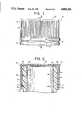
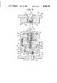
- FIG. 3is a front cross-sectional view through the mold used to form the cap shown in FIGS. 1 and 2, showing the mold in a closed position.
- FIG. 4is a side cross-sectional view through the mold shown in FIG. 3, showing the mold in an open position.
- FIG. 5is a top view showing the cams of the female member of the mold illustrated in FIGS. 3 and 4.
- FIG. 6is an enlarged view of a portion of FIG. 3, showing the mold cavity in which the cap is formed and the immediately adjacent parts of the mold in greater detail.
- FIGS. 7 and 8are similar to FIG. 6 and depict in sequential order different stages of the removal of tne cap from the mold.
- FIG. 9is a simplified view of a molding apparatus carrying a plurality of molds of the type shown in FIGS. 3 and 4.
- FIGS. 1 and 2show a plastic cap 10 generally comprised of a shell 12, a ring 14 and a plurality of frangible members 16. More specifically, shell 12 includes a cylindrical side wall or skirt portion 20, a top wall 22 extending across the top of the side wall, internal rib like threads 24 projecting radially inwardly from the side wall, and top sealing members 26 and 30 extending downwardly from the top wall of the cap.
- the ring 14is located directly below a bottom circumferential edge of the skirt portion of the shell 12, concentric therewith.
- the ring 14includes an inside annular rib 32 which projects radially inwardly of the main body of the ring.
- a plurality, for example eight, frangible members 16are uniformly spaced around the bottom of the skirt portion 20 and extend between the skirt portion and the ring 14 to connect the ring breakably thereto.
- the cap 10is fabricated from a relatively rigid plastic such as polypropylene.
- the cap 10is manufactured for use with a bottle or similar container having a neck 34 with an outer diameter approximately the same as the inner diameter of the cylindrical side wall 20.
- the neck 34forms a threaded recess 36 for receiving threads 24 of the container cap and a shoulder 40 for engaging the rib 32 of the cap ring 14.
- the cap 10is secured to the bottle by screwing or pressing the cap onto the neck 34.
- the ring 14slightly expands, slides past the shoulder 40, and then contracts so that the rib 32 extends directly below the shoulder.
- the top sealing members 26 and 30are brought into engagement with the top of the bottle neck 34.
- the shell 12As the cap 10 is unthreaded from the bottle neck 34, the shell 12 is moved upward and pulls the ring 14 upward therewith. Upward movement of the ring 14 is resisted however by contact between the rib 32 and the shoulder 40. This contact and resistance, first, develops tensile forces on the frangible members 16 connecting the ring 14 to the shell 12, and second, forces the rib 32 and those frangible members outwardly. The combination of the tensile forces and the outward flexing of the frangible members 16 breaks the members, separating the ring 14 from the shell 12. The shell 12 is then completely unthreaded from the bottle neck 34, opening the bottle and leaving the ring 14 behind.
- FIGS. 3 through 8illustrate a mold 50 for forming the cap 10.
- Mold 50comprises a female member 52 and a male member 54.
- the female member 52forms a socket 56 and an orifice 58 for conducting plastic material into that socket.
- a cavity plate 60 of female member 52forms a central opening 62 and a mold piece 64, which forms an upper portion of the socket 56, is disposed therein.
- a clamp plate 66extends over the mold piece 64 and over the cavity plate 60 and is bolted to the cavity plate to clamp the mold piece within the central opening 62.
- a material conduit 70is secured to the clamp plate 66 and forms an upper portion of the orifice 58.
- One or more water passages 72extend through female member 52, adjacent the socket 56, to conduct water through the female member of the mold 50 to cool material fed into the socket 56.
- a plurality of cams 74together form a lower portion of the socket 56, and these cams include radial projections 76 that engage circumferentially spaced section of male member 52, specifically a core assembly 78 thereof, to form the annular recess of the cap 10 between frangible members 16 thereof.
- the cams 74rest on and are supported by the male member 54 specifically a top surface 80 thereof, for sliding movement between a closed position, shown in FIG. 3, wherein the cams engage core assembly 78, and an open position, shown in FIG. 4, wherein the cams are spaced from the core assembly to facilitate removing cap 10 from the mold cavity in which the cap is formed.
- a spring 82is provided to urge the cams 74 from their closed position to their open position.
- the spring 82is a conventional clip spring with a circular shape and is positioned against radially inwardly facing surfaces of the cams 74, urging those cams radially outwardly, away from the core assembly 78.
- a grooveis formed in these radially inwardly facing surfaces of the cams 74 to hold the spring 82.
- a plurality of screws or bolts 84are threaded into the top surface 80 of male member 54 to limit outward movement of cams 74. Means other than springs 82 may be used to the move cams 74 to their open positions.
- a plurality of pinsmay be connected to the cavity plate 60 and slant downwardly outwardly into sockets formed in the cams, whereby the pins would push the cams outwardly when the cavity plate 60 is raised and push the cams 74 inwardly when the cavity plate is lowered.
- means 86illustrated in FIG. 5
- L-shaped pins, rails, gibs, or similar devicesmay be secured to the surface 80 to guide movement of the cams 74 between their open and closed positions and to hold those cams against upward axial movement away from the surface 80.
- the cams 74are moved from their open position to their closed position and are releasably held in the latter position by means of engagement between cooperating surfaces of the cams and the cavity plate 60. More specifically, the cams 74 have upper surfaces 90 that slant upwardly radially inwardly, and cavity plate 60 has a lower surface 92 directly above the upper surfaces 90 of the cams and that also slants upwardly radially inwardly. As cavity plate 60 moves downwardly from its open position, shown in FIG. 4, to its closed position, shown in FIG. 3, the surface 92 of the cavity plate contacts the surfaces 90 of the cams 74 and forces those cams radially inwardly to their closed position. As the cavity plate 60 is held in its closed position, the surface 92 holds the cams 74 in their closed position.
- inside edges of the radial protrusions 76 of the cams 74have a plurality of circumferentially spaced grooves 94.
- the grooves 94form openings extending between the cams and the core assembly 78.
- the frangible members 16 of the cap 10are formed in those openings.
- the embodiment of mold 50 shown in the drawingsincludes four cams 74, the mold may be provided with fewer or more cams, for example two, six, or eight, without departing from the scope of the present invention.
- cavity plate 60, mold piece 64, clamp plate 66, and material conduit 70comprise an upper assembly of female member 52 of mold 50; and cams 74, spring 82, and guide means 86 comprise a lower assembly of the female member.
- a support assembly 96 of male member 54provides a base of support for the female member 52 and the other parts of the male member of the mold 50.
- Plates 98 and 100 of the assembly 96are generally horizontal and parallel, and these plates form generally aligned central openings 102 and 104 respectively.
- Spacer blocks 106 and 110 of the support assembly 96extend between the plates 98 and 100, across the bottom left and right sides of the mold 50. The various plates and blocks of the support assembly 96 are secured together by a plurality of bolts to form a rigid, unitary assembly.
- the core assembly 78 of male member 54when the mold 50 is in the closed, or cap forming position, shown in FIG. 3, the core assembly 78 axially extends into the socket 56 to form, with the female member 52, the particular mold cavity in which the cap 10 is formed. More specifically, an outer core piece 112 rests on the upper plate 98 of the support assembly 96 and extends axially upwardly therefrom. Tne upper portion of the outer core piece 112 extends into the socket 56 of the female member 52 and, during formation of cap 10, forms the interior of the sides and a portion of the interior of the top of the cap.
- the upper portion of the outer core piece 112includes a first annular recess 114 which is used to form the rib 32 on the ring of the cap 10 and a second annular recess 116 to form the threads 24 of the cap.
- the outer core piece 112is axially held in place by means of a retainer sleeve 118 and a retainer ring 120.
- the bottom portion of the outer core piece 112includes a radially outwardly extending shoulder, and the retainer sleeve 118 includes a downwardly facing radial surface that extends directly over that shoulder of the outer core member.
- the lower portion of the retainer sleeve 118includes a radially outwardly extending shoulder, and the retainer ring 120 includes a downwardly facing radial surface that extends directly over that shoulder of the retainer sleeve.
- the retainer ring 120itself is securely bolted to the top plate 98 of support assembly 96.
- the interior of the outer core piece 112forms an axial through bore, and an inner core piece 122 extends therein and is supported for axial movement relative to the outer core piece.
- the upper portions of the inner core piece 122 and the through bore of outer core piece 112are both flared out.
- the top surface of the inner core piece 122is substantially coplanar with the top surface of the outer core piece 112 and, during formation of the cap 10, forms the major portion of the interior surface of the top of the cap.
- the outer and inner core pieces 112 and 122together form a top axial recess 124 in which top annular sealing member 26 of the cap 10 is formed, and the inner core piece 122 forms a top axially slanted recess 126 in which the top annular sealing member 30 of the cap is formed.
- the inner core piece 122includes a separable upper insert that is in a tight pressure fit with the main body of the inner core piece, and these two pieces in combination form the recess 126.
- the inner core piece 122also defines an axial through bore and a knockout pin 130 axially extends therein and is supported for axial movement relative to the inner core piece.
- the knockout pin 130generally is a smooth, solid cylinder, with a small annular shoulder 132 extending outward from the bottom of the pin.
- the top surface of the knockout pin 130is coplanar with the top surface of the inner core piece 122, and the knockout pin extends downwardly therefrom, through the inner core member, to a position below the bottom thereof.
- One or more water passages 134extend through the knockout pin 130 to conduct water therethrough, adjacent the mold cavity in which the cap 10 is formed, to cool material fed into the mold cavity.
- a stripping assembly 136is provided to push cap 10 axially off core assembly 78.
- the stripping assembly 136includes a ring 138 and a plate 140.
- Ring 138extends around core assembly 78, below the mold cavity in which the cap 10 is formed, to push the bottom of the cap off the core assembly, and the ring 138 rests directly on plate 140 so that upward movement of the plate 140 moves the ring 138 upwardly.
- an upper portion of ring 138tightly fits around an intermediate portion of outer core piece 112 and forms the bottom of the mold cavity in which cap 10 is formed.
- An outer portion of ring 138forms a radially outwardly extending shoulder 142 that rests on the top surface 80 of the plate 140.
- the plate 140directly rests on the top support plate 98 when the mold 50 is in the closed position shown in FIG. 3.
- the plate 140is free to move upward away from support plate 98 for a limited distance, and means such as springs 150 are provided to move the plate 140 upward relative to that support plate.
- the plate 140 and support plate 98form a plurality of recesses, and sprin9s 150, which may be conventional coil springs, are located in these recesses, urging plates 140 and 98 axially apart.
- means other than conventional coil springsfor example air or hydraulic cylinders, may be used to move the plate 140 away from the support plate 98.
- Means such as bolts 152may be used to guide axial movement of the plate 140 away from and towards support plate 98 and to limit axial movement of the plate 140 away from that support plate.
- a first ejector assembly 154is located between plates 92, 94, 96 and 100, and engages the inner core piece 122 to push that core piece upward to help push the cap 10 off the outer core piece 112.
- Plates 156 and 158 of the ejector assembly 154form central openings, with the inner core member 122 extending through those openings in a close radial fit with the surfaces thereof.
- Bolts 152extend between the plate 156 and the plate 140 to move the former plate axially upward with the latter plate, and bolts 160 (only one is shown in the drawings) connect the plate 158 to the plate 156 for unitary axial movement.
- a retainer ring 162which may be a conventional snap ring, is secured within an annular groove formed in the lower portion of the outside surface of the interior core member 122, extends radially outward therefrom, and is tightly captured between the plates 156 and 158. In this manner, upward movement of the plate 158 forces the ring 160, and thus the core member 122, upward therewith; while downward movement of the plate 156 forces the ring 160, and hence the core member 122, downward therewith.
- a second ejector assembly 164is located directly below the first ejector assembly 154 and engages the knockout pin 130 to push that pin upward.
- a plate 166 of the second ejector assembly 164extends directly below and contacts the bottom of the knockout pin 130.
- Another plate 168 of the ejector assembly 164is located above the plate 166, is connected thereto by means of bolts 170 (only one is shown in the drawings), and forms a central axial opening through which the knockout pin 130 extends.
- the plate 168forms a downwardly facing radial surface that extends directly over the shoulder 132 of the knockout pin 130.
- Bolts 178are secured to the plate 158 of the first ejector assembly 154 and extend through the plates 166 and 168 of the second ejector assembly 164 to guide axial movement of the second ejector assembly within the mold 50.
- the bolts 178also serve to pull the first ejector assembly 154 downward with the second ejector assembly 164 after the former assembly has moved a pre-set, limited distance downward relative to the latter assembly.
- the mold 50is connected to a molding apparatus 180, schematically shown in FIG. 9, that, first, supports the mold 50, and second, operates to raise and to lower the knockout bars 174, the upper assembly of the female member 52, and the stripping assembly 136 of the male member 54.
- a molding apparatus 180that carries twenty or thirty molds 50 may use two, four, or six air cylinders 182 to raise the cap stripper mechanisms of the molds.
- plastic materialis injected through the orifice 158 to fill the mold cavity formed between the female and male members 52 and 54. Cooling water is conducted through the water passages 72 and 134 of the mold 50, and the plastic material in the mold cavity cools and hardens.
- the portion of the male member 52 adjacent the mold cavity in which the cap 10 is formedmay be maintained at 400° F. while the portion of the female member 54 adjacent that mold cavity may be maintained at 600° F. Because of this temperature difference, as the plastic material in the mold cavity hardens, the material in the mold cavity shrinks onto the male member 52, specifically the core assembly 78 thereof, and a space develops between the cap 10 and the female member 54, specifically mold piece 64 thereof.
- the female member 54is removed from the cap. With reference to FIGS. 4 and 9, this is done by moving the upper assembly of the female member 54 upwardly axially and the lower assembly of the female member 54 radially away from the cap 10. This is done by expanding cylinders 184 of molding apparatus 180, which raises plate 186 thereof, which in turn, raises clamp plate 66, cavity plate 60, and mold piece 64 of mold 50. Since the cams 74 are spring biased to their open position and are releasably held in their closed position by the pressure exerted on the caps by the cavity plate 60, is soon as the cavity plate is moved away from the cams, those cams automatically slide outward along the surface 80, away from the cap 10.
- the cap 10is removed from the male member 54. This is done through coordinated movement of the stripping assembly 136, the inner core piece 122, the knockout pin 130, and the first and second ejector assemblies 154 and 164. As the cavity plate 60 of the female member 52 is moved upwardly, the plate 140 becomes free to move upwardly, and the plate 140 is moved upwardly by the springs 150. Alternatively, with the arrangement depicted in FIG. 9, plate 140 may be moved upwardly by means of cylinders 182 and plate 190, which is rigidly secured to the plates 140 of the molds 50 shown in FIG. 9.
- the frangible members 16 of the cap 10are not stretched, but rather are compressed, as the rib 32 is removed from the recess in which the rib 32 is formed.
- the cap 10may be removed from the mold 50 without exerting appreciable tensile forces on the frangible members 16.
- the inner core piece 122 and the knockout pin 130are moved upwardly to push the top of the container cap away from the outer core piece 112.
- the inner core piece 122is moved upwardly by means of the first ejector assembly 154 which, as discussed above, is pulled upwardly with the plate 140 by means of the bolts 152.
- the knockout pin 130is pushed upwardly by the second ejector assembly 164, which itself is moved upwardly by the knockout bars 174.
- the knockout bars 174are pushed upward via cylinders 192 and plate 194 of molding apparatus 180.
- the stripper plate 140, the ring 138, the first ejector assembly 154, and the inner core piece 122continue to move upwardly until the plate 156 of the first ejector assembly abutts against the plate 98, as shown in FIG. 4, terminating the upwardly movement of the plate 156, the first ejector assembly, and the inner core piece.
- the plate 156 of the ejector assembly 154also prevents further upwardly movement of the bolts 152, preventing further upwardly movement of the plate 140. Because the plate 140 can no longer move upwardly, that plate does not force the cams 74 or the ring 138 further upwardly, and the cams and the ring 138 come to a stop.
- FIG. 8The position of the plate 140, the ring 138, the inner core piece 122, and the knockout pin 130 when upwardly movement of the plate 140, the ring 138, and the inner core piece is terminated is shown in FIG. 8. It should be noted that the ring 138 is employed to push the rib 32 of the cap 10 past the recess 116 in which the threads 24 of the container cap are formed. In this way, the frangible members 16 of the cap 10 are not stretched in case the rib 32 rubs against upper surfaces of the recess 116 as that rib slides upwardly therepast.
- the knockout pin 130is free to continue to move upwardly from the position shown in FIG. 8, however, and the knockout pin is so moved by further upwardly movement of the second ejector assembly 164.
- Tne knockout pin 130directly contacts the central portion of the top of the cap 10, and as the knockout pin is pushed upwardly, the knockout pin forces the cap completely off and away from the outer and the inner core pieces 112 and 122, from the position shown in FIG. 8 to the position shown in broken lines in FIG. 4. From this position, the cap 10 may be lifted off the knockout pin 130, and completely removed from the mold 50 by hand.
- the knockout bars 174are pulled downwardly to the position shown in FIG. 3, pulling the second elector assembly 164 and the knockout pin 130 downwardly into their position shown in FIG. 3.
- that plateengages the head of the bolt 178 and pulls that bolt downwardly.
- that plateforces the inner core piece 102 downward via the retainer ring 162 and, at the same time, forces the bolts 152 downward, which in turn pulls the plate 140 downward.
Landscapes
- Engineering & Computer Science (AREA)
- Mechanical Engineering (AREA)
- Manufacturing & Machinery (AREA)
- Closures For Containers (AREA)
Abstract
Description
Claims (7)
Priority Applications (1)
| Application Number | Priority Date | Filing Date | Title |
|---|---|---|---|
| US07/150,686US4806301A (en) | 1984-08-15 | 1988-02-01 | Process of removing a plastic cap from a mold |
Applications Claiming Priority (3)
| Application Number | Priority Date | Filing Date | Title |
|---|---|---|---|
| US06/640,899US4618121A (en) | 1984-08-15 | 1984-08-15 | Mold for forming plastic cap with perforation about the periphery of the skirt |
| US85662686A | 1986-04-25 | 1986-04-25 | |
| US07/150,686US4806301A (en) | 1984-08-15 | 1988-02-01 | Process of removing a plastic cap from a mold |
Related Parent Applications (1)
| Application Number | Title | Priority Date | Filing Date |
|---|---|---|---|
| US85662686AContinuation | 1984-08-15 | 1986-04-25 |
Publications (1)
| Publication Number | Publication Date |
|---|---|
| US4806301Atrue US4806301A (en) | 1989-02-21 |
Family
ID=27387019
Family Applications (1)
| Application Number | Title | Priority Date | Filing Date |
|---|---|---|---|
| US07/150,686Expired - Fee RelatedUS4806301A (en) | 1984-08-15 | 1988-02-01 | Process of removing a plastic cap from a mold |
Country Status (1)
| Country | Link |
|---|---|
| US (1) | US4806301A (en) |
Cited By (31)
| Publication number | Priority date | Publication date | Assignee | Title |
|---|---|---|---|---|
| US4933133A (en)* | 1988-05-11 | 1990-06-12 | Brown Edward M | Container closure and method for manufacture thereof |
| US5086938A (en)* | 1988-02-16 | 1992-02-11 | Aichinger Dietmar F | Pilfer-proof closure for containers and injection mould for producing the closure |
| US5230856A (en)* | 1990-05-21 | 1993-07-27 | Frank Schellenbach | Method for demolding a safety-seal strip of a closure cap |
| US5240155A (en)* | 1992-02-05 | 1993-08-31 | Seaquist Closures | Closure with integral twist ring |
| US5281385A (en)* | 1992-10-21 | 1994-01-25 | Sunbeam Plastics Corporation | Injection molding system for threaded tamper indicating closures |
| US5881909A (en)* | 1993-02-01 | 1999-03-16 | Maytag Corporation | Plastic washing machine basket |
| WO2000021874A1 (en)* | 1998-10-13 | 2000-04-20 | Portola Packaging, Inc. | Apparatus and method for forming cap |
| US6099785A (en)* | 1998-03-17 | 2000-08-08 | Schweigert; Lothar | Method for injection molding plastic closures |
| US6213666B1 (en)* | 1995-05-24 | 2001-04-10 | Merz & Krell Gmbh & Co. | Production of releasable sleeve sections |
| USD442090S1 (en) | 2000-03-29 | 2001-05-15 | Pechiney Plastic Packaging, Inc. | Closure |
| US6241931B1 (en)* | 1998-06-01 | 2001-06-05 | Top Grade Machining Ltd. | Threaded lid injection mold release |
| WO2001070586A1 (en)* | 2000-03-16 | 2001-09-27 | Pechiney Plastic Packaging, Inc. | Molded closure with flex areas and method |
| US6325225B1 (en)* | 1992-07-16 | 2001-12-04 | Closures And Packaging Services Limited | Tamper evident closure |
| US6355201B1 (en) | 2000-09-07 | 2002-03-12 | Captive Plastics, Inc. | Tamper-indicating closure with resilient locking projections |
| US6426030B1 (en) | 1999-11-15 | 2002-07-30 | Rexam Medical Packaging Inc. | Method of making a molded internally threaded closure |
| WO2002092319A1 (en)* | 2001-05-16 | 2002-11-21 | Accurate Mold Usa, Ltd. | Staged, sequentially separated injection mold |
| US6506330B1 (en) | 1998-03-17 | 2003-01-14 | Lothar Schweigert | Apparatus and method for molding plastic closures |
| ES2193794A1 (en)* | 2000-03-22 | 2003-11-01 | Plastivit Sa | Fabrication of injection molded plastics parts assemblies consists of forming in half molds |
| US7150847B2 (en) | 2002-05-15 | 2006-12-19 | Accurate Mold Usa, Ltd. | Staged, sequentially separated injection mold |
| US7427373B1 (en)* | 2004-09-01 | 2008-09-23 | Pacific Management Holding, Llc | Method and apparatus for forming a closure device and a container |
| US20080284064A1 (en)* | 2007-05-16 | 2008-11-20 | Allen Tool Company, Inc. | Process of making a closure adapted to be used with a container |
| US20110056948A1 (en)* | 2009-09-04 | 2011-03-10 | Pacific Management Holding, Llc | Pharmaceutical Container Having Non-Child-Resistant Closure |
| US20110100950A1 (en)* | 2008-07-11 | 2011-05-05 | Tetra Laval Holdings & Finance S.A. | Stopper for a container neck and a molding machine for molding a plastics material for the purpose of fabricating such a stopper |
| WO2011130847A1 (en) | 2010-04-23 | 2011-10-27 | Husky Injection Molding Systems Ltd. | Molding apparatus |
| WO2012033451A1 (en)* | 2010-09-07 | 2012-03-15 | Petro Pack Ab | A package closure and a device and a method for producing a package closure |
| WO2012136472A1 (en)* | 2011-04-04 | 2012-10-11 | Lindal France Sas | Injection-moulding press |
| US20130025559A1 (en)* | 2011-06-10 | 2013-01-31 | Honda Motor Co., Ltd. | High pressure die casting flash containment system |
| WO2014088500A1 (en)* | 2012-12-05 | 2014-06-12 | Petro-Pack Ab | A package closure and a device and a method for producing a package closure and use of such a device |
| US20150144398A1 (en)* | 2013-11-26 | 2015-05-28 | Andrew Llc | Adapter for sealing cover for electrical interconnections |
| US20150145170A1 (en)* | 2013-11-26 | 2015-05-28 | Eveready Battery Company Inc. | Method of Making A Bayonet Sealing Closure For Containers and Lids |
| WO2016080898A1 (en)* | 2014-11-21 | 2016-05-26 | Petro-Pack Ab | A method and a device for producing a package closure |
Citations (31)
| Publication number | Priority date | Publication date | Assignee | Title |
|---|---|---|---|---|
| US1918532A (en)* | 1930-05-02 | 1933-07-18 | Inland Mfg Co | Molding press |
| US2948031A (en)* | 1957-09-09 | 1960-08-09 | Thomas L Webb | Piston molding core |
| US3265797A (en)* | 1962-08-30 | 1966-08-09 | Grace W R & Co | Method of injection molding solid heavy section |
| US3325576A (en)* | 1964-02-03 | 1967-06-13 | Kessler Milton | Method of making unitary plastic sealing cap |
| DE2356007A1 (en)* | 1972-11-10 | 1974-05-22 | Metal Box Co Ltd | MISUSE-PROOF SCREW CAP |
| DE2300589A1 (en)* | 1973-01-08 | 1974-07-11 | Huels Chemische Werke Ag | Injection moulding thermoplastics articles of non-uniform hardness - in which temp. during at least half of the moulding is above, and in remainder below, vitrifying point |
| US3855380A (en)* | 1971-06-09 | 1974-12-17 | Wheeling Stamping Co | Method for manufacturing unitary, seamless, collapsible thermoplastic tubes |
| US3905740A (en)* | 1973-11-19 | 1975-09-16 | Beatrice Foods Co | Molding apparatus |
| US3929246A (en)* | 1974-02-25 | 1975-12-30 | Koninkl Emballag Ind Van Leer | Plastic container cap unit with integral sealing ring |
| US3940103A (en)* | 1974-02-21 | 1976-02-24 | Captocap Limited | Apparatus for injection molding a tamper-proof plastic cap |
| US3987144A (en)* | 1973-07-19 | 1976-10-19 | Stapla Stahl - Und Plastikverarbeitung Gmbh & Co. Kg. | Method for the removal of a mold core from an injection molded plastic duct section |
| US4147268A (en)* | 1976-09-24 | 1979-04-03 | Patel Chandrakant S | Pilfer-proof closure for containers |
| US4155698A (en)* | 1975-04-08 | 1979-05-22 | Albert Obrist Ag | Method and apparatus for injection molding of plastic closures |
| EP0004500A2 (en)* | 1978-03-28 | 1979-10-03 | Captocap Limited | Plastic tamperproof closure and mould for the manufacture thereof |
| US4196818A (en)* | 1977-12-14 | 1980-04-08 | Metal Closures Group Limited | Closures for containers |
| US4212623A (en)* | 1979-01-31 | 1980-07-15 | Logic Devices, Inc. | Apparatus for cooling plastic injection mold dies |
| US4241841A (en)* | 1979-05-07 | 1980-12-30 | Consumers Glass Company Ltd. | Severable connecting means |
| US4286766A (en)* | 1980-04-18 | 1981-09-01 | Holdt J W Von | Collapsible mold core |
| US4299328A (en)* | 1980-03-26 | 1981-11-10 | Anchor Hocking Corporation | Tamperproof bottle closure cap |
| US4322012A (en)* | 1980-05-09 | 1982-03-30 | Dairy Cap Corporation | Threaded plastic bottle cap |
| US4343408A (en)* | 1980-04-21 | 1982-08-10 | General Kap (P.R.) Corporation | Tamper-evident plastic closure |
| EP0068714A1 (en)* | 1981-06-25 | 1983-01-05 | BP Chemicals Limited | Thermal-forming processes |
| US4383819A (en)* | 1980-07-16 | 1983-05-17 | Letica Corporation | Apparatus for forming a container |
| US4461390A (en)* | 1980-04-21 | 1984-07-24 | General Kap (P.R.) Corporation | Tamper-evident plastic closure |
| EP0117510A1 (en)* | 1983-02-24 | 1984-09-05 | Jobst Ulrich Gellert | Injection molding core ring gate system |
| US4496302A (en)* | 1982-06-04 | 1985-01-29 | Husky Injection Molding Systems Inc. | Apparatus for molding plastic articles |
| US4502660A (en)* | 1983-11-21 | 1985-03-05 | Luther Leroy D | Mold including side walls with locking projections |
| US4503985A (en)* | 1983-10-20 | 1985-03-12 | Owens-Illinois, Inc. | Tamper indicating package with large diameter opening |
| US4518554A (en)* | 1982-09-14 | 1985-05-21 | Yoshida Industry Co., Ltd. | Method and apparatus for molding a tubular container with a cap |
| US4541795A (en)* | 1984-07-31 | 1985-09-17 | James R. Goldberg | Injection mold for a bottle closure device |
| US4552328A (en)* | 1984-01-05 | 1985-11-12 | Sun Coast Plastics, Inc. | Mold for making tamper-proof closure |
- 1988
- 1988-02-01USUS07/150,686patent/US4806301A/ennot_activeExpired - Fee Related
Patent Citations (32)
| Publication number | Priority date | Publication date | Assignee | Title |
|---|---|---|---|---|
| US1918532A (en)* | 1930-05-02 | 1933-07-18 | Inland Mfg Co | Molding press |
| US2948031A (en)* | 1957-09-09 | 1960-08-09 | Thomas L Webb | Piston molding core |
| US3265797A (en)* | 1962-08-30 | 1966-08-09 | Grace W R & Co | Method of injection molding solid heavy section |
| US3325576A (en)* | 1964-02-03 | 1967-06-13 | Kessler Milton | Method of making unitary plastic sealing cap |
| US3855380A (en)* | 1971-06-09 | 1974-12-17 | Wheeling Stamping Co | Method for manufacturing unitary, seamless, collapsible thermoplastic tubes |
| DE2356007A1 (en)* | 1972-11-10 | 1974-05-22 | Metal Box Co Ltd | MISUSE-PROOF SCREW CAP |
| DE2300589A1 (en)* | 1973-01-08 | 1974-07-11 | Huels Chemische Werke Ag | Injection moulding thermoplastics articles of non-uniform hardness - in which temp. during at least half of the moulding is above, and in remainder below, vitrifying point |
| US3987144A (en)* | 1973-07-19 | 1976-10-19 | Stapla Stahl - Und Plastikverarbeitung Gmbh & Co. Kg. | Method for the removal of a mold core from an injection molded plastic duct section |
| US3905740A (en)* | 1973-11-19 | 1975-09-16 | Beatrice Foods Co | Molding apparatus |
| US3940103A (en)* | 1974-02-21 | 1976-02-24 | Captocap Limited | Apparatus for injection molding a tamper-proof plastic cap |
| US3929246A (en)* | 1974-02-25 | 1975-12-30 | Koninkl Emballag Ind Van Leer | Plastic container cap unit with integral sealing ring |
| US4155698A (en)* | 1975-04-08 | 1979-05-22 | Albert Obrist Ag | Method and apparatus for injection molding of plastic closures |
| US4147268A (en)* | 1976-09-24 | 1979-04-03 | Patel Chandrakant S | Pilfer-proof closure for containers |
| US4196818A (en)* | 1977-12-14 | 1980-04-08 | Metal Closures Group Limited | Closures for containers |
| EP0004500A2 (en)* | 1978-03-28 | 1979-10-03 | Captocap Limited | Plastic tamperproof closure and mould for the manufacture thereof |
| US4346811A (en)* | 1978-03-28 | 1982-08-31 | Captocap Limited | Pilfer-proof closure cap of plastic material |
| US4212623A (en)* | 1979-01-31 | 1980-07-15 | Logic Devices, Inc. | Apparatus for cooling plastic injection mold dies |
| US4241841A (en)* | 1979-05-07 | 1980-12-30 | Consumers Glass Company Ltd. | Severable connecting means |
| US4299328A (en)* | 1980-03-26 | 1981-11-10 | Anchor Hocking Corporation | Tamperproof bottle closure cap |
| US4286766A (en)* | 1980-04-18 | 1981-09-01 | Holdt J W Von | Collapsible mold core |
| US4461390A (en)* | 1980-04-21 | 1984-07-24 | General Kap (P.R.) Corporation | Tamper-evident plastic closure |
| US4343408A (en)* | 1980-04-21 | 1982-08-10 | General Kap (P.R.) Corporation | Tamper-evident plastic closure |
| US4322012A (en)* | 1980-05-09 | 1982-03-30 | Dairy Cap Corporation | Threaded plastic bottle cap |
| US4383819A (en)* | 1980-07-16 | 1983-05-17 | Letica Corporation | Apparatus for forming a container |
| EP0068714A1 (en)* | 1981-06-25 | 1983-01-05 | BP Chemicals Limited | Thermal-forming processes |
| US4496302A (en)* | 1982-06-04 | 1985-01-29 | Husky Injection Molding Systems Inc. | Apparatus for molding plastic articles |
| US4518554A (en)* | 1982-09-14 | 1985-05-21 | Yoshida Industry Co., Ltd. | Method and apparatus for molding a tubular container with a cap |
| EP0117510A1 (en)* | 1983-02-24 | 1984-09-05 | Jobst Ulrich Gellert | Injection molding core ring gate system |
| US4503985A (en)* | 1983-10-20 | 1985-03-12 | Owens-Illinois, Inc. | Tamper indicating package with large diameter opening |
| US4502660A (en)* | 1983-11-21 | 1985-03-05 | Luther Leroy D | Mold including side walls with locking projections |
| US4552328A (en)* | 1984-01-05 | 1985-11-12 | Sun Coast Plastics, Inc. | Mold for making tamper-proof closure |
| US4541795A (en)* | 1984-07-31 | 1985-09-17 | James R. Goldberg | Injection mold for a bottle closure device |
Non-Patent Citations (3)
| Title |
|---|
| McKelvey, J. M., Polymer Processing, New York, John Wiley and Sons, (1962), pp. 340 345.* |
| McKelvey, J. M., Polymer Processing, New York, John Wiley and Sons, (1962), pp. 340-345. |
| Randolph et al., Plastics Engineering Handbook, Reinhold, New York (1960), pp. 287, 289.* |
Cited By (46)
| Publication number | Priority date | Publication date | Assignee | Title |
|---|---|---|---|---|
| US5086938A (en)* | 1988-02-16 | 1992-02-11 | Aichinger Dietmar F | Pilfer-proof closure for containers and injection mould for producing the closure |
| US4933133A (en)* | 1988-05-11 | 1990-06-12 | Brown Edward M | Container closure and method for manufacture thereof |
| US5230856A (en)* | 1990-05-21 | 1993-07-27 | Frank Schellenbach | Method for demolding a safety-seal strip of a closure cap |
| US5240155A (en)* | 1992-02-05 | 1993-08-31 | Seaquist Closures | Closure with integral twist ring |
| US6705479B2 (en) | 1992-07-16 | 2004-03-16 | Closures And Packaging Services Limited | Tamper evident closure |
| US6325225B1 (en)* | 1992-07-16 | 2001-12-04 | Closures And Packaging Services Limited | Tamper evident closure |
| US5281385A (en)* | 1992-10-21 | 1994-01-25 | Sunbeam Plastics Corporation | Injection molding system for threaded tamper indicating closures |
| US5881909A (en)* | 1993-02-01 | 1999-03-16 | Maytag Corporation | Plastic washing machine basket |
| US5980809A (en)* | 1993-02-01 | 1999-11-09 | Maytag Corporation | Method for molding a plastic washing machine basket |
| US6213666B1 (en)* | 1995-05-24 | 2001-04-10 | Merz & Krell Gmbh & Co. | Production of releasable sleeve sections |
| US6099785A (en)* | 1998-03-17 | 2000-08-08 | Schweigert; Lothar | Method for injection molding plastic closures |
| US6506330B1 (en) | 1998-03-17 | 2003-01-14 | Lothar Schweigert | Apparatus and method for molding plastic closures |
| US6241931B1 (en)* | 1998-06-01 | 2001-06-05 | Top Grade Machining Ltd. | Threaded lid injection mold release |
| US6177041B1 (en)* | 1998-10-13 | 2001-01-23 | Portola Packaging, Inc. | Method for forming cap with tear line |
| WO2000021874A1 (en)* | 1998-10-13 | 2000-04-20 | Portola Packaging, Inc. | Apparatus and method for forming cap |
| US6426030B1 (en) | 1999-11-15 | 2002-07-30 | Rexam Medical Packaging Inc. | Method of making a molded internally threaded closure |
| WO2001070586A1 (en)* | 2000-03-16 | 2001-09-27 | Pechiney Plastic Packaging, Inc. | Molded closure with flex areas and method |
| ES2193794A1 (en)* | 2000-03-22 | 2003-11-01 | Plastivit Sa | Fabrication of injection molded plastics parts assemblies consists of forming in half molds |
| ES2193794B1 (en)* | 2000-03-22 | 2005-02-01 | Plastivit S.A. | PROCEDURE FOR THE MANUFACTURE OF A SET OF INJECTED PLASTIC MATERIAL PARTS, AND DEVICE AND ASSEMBLY OF CORRESPONDING PARTS. |
| USD442090S1 (en) | 2000-03-29 | 2001-05-15 | Pechiney Plastic Packaging, Inc. | Closure |
| US6729488B2 (en) | 2000-09-07 | 2004-05-04 | Captive Plastics, Inc. | Tamper-indicating closure with resilient locking projections |
| US6355201B1 (en) | 2000-09-07 | 2002-03-12 | Captive Plastics, Inc. | Tamper-indicating closure with resilient locking projections |
| WO2002092319A1 (en)* | 2001-05-16 | 2002-11-21 | Accurate Mold Usa, Ltd. | Staged, sequentially separated injection mold |
| US7150847B2 (en) | 2002-05-15 | 2006-12-19 | Accurate Mold Usa, Ltd. | Staged, sequentially separated injection mold |
| US20090101616A1 (en)* | 2004-09-01 | 2009-04-23 | Pacific Management Holding, Llc | Method and apparatus for forming a closure device and a container |
| US7427373B1 (en)* | 2004-09-01 | 2008-09-23 | Pacific Management Holding, Llc | Method and apparatus for forming a closure device and a container |
| US20080272515A1 (en)* | 2004-09-01 | 2008-11-06 | Brennan Sean M | Method and apparatus for forming a closure device and a container |
| US20080284064A1 (en)* | 2007-05-16 | 2008-11-20 | Allen Tool Company, Inc. | Process of making a closure adapted to be used with a container |
| US7687004B2 (en)* | 2007-05-16 | 2010-03-30 | Allen Tool Company, Inc. | Process of making a closure adapted to be used with a container |
| US20110100950A1 (en)* | 2008-07-11 | 2011-05-05 | Tetra Laval Holdings & Finance S.A. | Stopper for a container neck and a molding machine for molding a plastics material for the purpose of fabricating such a stopper |
| US8631954B2 (en)* | 2008-07-11 | 2014-01-21 | Tetra Laval Holdings & Finance S.A. | Stopper for a container neck and a molding machine for molding a plastics material for the purpose of fabricating such a stopper |
| US20110056948A1 (en)* | 2009-09-04 | 2011-03-10 | Pacific Management Holding, Llc | Pharmaceutical Container Having Non-Child-Resistant Closure |
| WO2011130847A1 (en) | 2010-04-23 | 2011-10-27 | Husky Injection Molding Systems Ltd. | Molding apparatus |
| US8834149B2 (en) | 2010-04-23 | 2014-09-16 | Husky Injection Molding Systems Ltd. | Molding apparatus |
| WO2012033451A1 (en)* | 2010-09-07 | 2012-03-15 | Petro Pack Ab | A package closure and a device and a method for producing a package closure |
| US9919831B2 (en) | 2010-09-07 | 2018-03-20 | Petro Pack Ab | Package closure and a device and a method for producing a package closure |
| WO2012136472A1 (en)* | 2011-04-04 | 2012-10-11 | Lindal France Sas | Injection-moulding press |
| RU2581374C2 (en)* | 2011-04-04 | 2016-04-20 | Лендаль Франс Сас | Press for pressure casting |
| US9539748B2 (en) | 2011-04-04 | 2017-01-10 | Lindal France Sas | Injection-molding press |
| US20130025559A1 (en)* | 2011-06-10 | 2013-01-31 | Honda Motor Co., Ltd. | High pressure die casting flash containment system |
| WO2014088500A1 (en)* | 2012-12-05 | 2014-06-12 | Petro-Pack Ab | A package closure and a device and a method for producing a package closure and use of such a device |
| US20150144398A1 (en)* | 2013-11-26 | 2015-05-28 | Andrew Llc | Adapter for sealing cover for electrical interconnections |
| US20150145170A1 (en)* | 2013-11-26 | 2015-05-28 | Eveready Battery Company Inc. | Method of Making A Bayonet Sealing Closure For Containers and Lids |
| US9944005B2 (en)* | 2013-11-26 | 2018-04-17 | Edgewell Personal Care Brands, Llc. | Method of making a bayonet sealing closure for containers and lids |
| US10404048B2 (en)* | 2013-11-26 | 2019-09-03 | Commscope Technologies Llc | Adapter for sealing cover for electrical interconnections |
| WO2016080898A1 (en)* | 2014-11-21 | 2016-05-26 | Petro-Pack Ab | A method and a device for producing a package closure |
Similar Documents
| Publication | Publication Date | Title |
|---|---|---|
| US4806301A (en) | Process of removing a plastic cap from a mold | |
| US4618121A (en) | Mold for forming plastic cap with perforation about the periphery of the skirt | |
| US4552328A (en) | Mold for making tamper-proof closure | |
| US4526282A (en) | Tamper proof closure cap, method, and tool for making same | |
| US4155698A (en) | Method and apparatus for injection molding of plastic closures | |
| US4496302A (en) | Apparatus for molding plastic articles | |
| US5736173A (en) | Preform injection mould with slide taper locks | |
| US5230856A (en) | Method for demolding a safety-seal strip of a closure cap | |
| US2891283A (en) | Apparatus for molding parts having irregular outer surfaces | |
| CA2103759C (en) | High torque battery terminal and method of making same | |
| US6177041B1 (en) | Method for forming cap with tear line | |
| US5820807A (en) | Staged, sequentially separated injection mold method for forming container closures | |
| US4564112A (en) | Closure cap for a container | |
| US4519569A (en) | Molding | |
| US4564113A (en) | Injection molded plastic closure | |
| USRE19000E (en) | Molding of plastic articles | |
| US4881892A (en) | Apparatus for making tamper-evident closures | |
| US7150847B2 (en) | Staged, sequentially separated injection mold | |
| CA1270108A (en) | Method for making pilfer-proof cap | |
| NZ208039A (en) | Tamper proof closure cap designed to facilitate easy removal from its forming mould | |
| CA2447430C (en) | Staged, sequentially separated injection mold | |
| GB2172239A (en) | Method and mould for a cap with a tamper-evident band | |
| US3224616A (en) | Closure and method of making same | |
| CN115592869B (en) | Container lid demoulding mechanism | |
| GB2269372A (en) | Cap with tamper-evident band |
Legal Events
| Date | Code | Title | Description |
|---|---|---|---|
| AS | Assignment | Owner name:KEY BANK OF EASTERN NEW YORK, N.A. Free format text:SECURITY INTEREST;ASSIGNOR:AMERICAN SAFETY CLOSURE CORP., A CORPORATION OF NY;REEL/FRAME:005789/0453 Effective date:19910715 | |
| REMI | Maintenance fee reminder mailed | ||
| LAPS | Lapse for failure to pay maintenance fees | ||
| FP | Lapsed due to failure to pay maintenance fee | Effective date:19930221 | |
| AS | Assignment | Owner name:BANK OF NOVA SCOTIA, THE, GEORGIA Free format text:SECURITY AGREEMENT;ASSIGNOR:CCL PLASTIC (PLATTSBURGH), INC.;REEL/FRAME:013933/0142 Effective date:20030829 | |
| AS | Assignment | Owner name:INTRAPAC (PLATTSBURGH) INC., NEW YORK Free format text:CHANGE OF NAME;ASSIGNOR:CCL PLASTIC (PLATTSBURGH), INC.;REEL/FRAME:014567/0547 Effective date:20030917 | |
| AS | Assignment | Owner name:INTRAPAC (PLATTSBURGH) INC., NEW YORK Free format text:CHANGE OF NAME;ASSIGNOR:CCL PLASTIC (PLATTSBURGH), INC.;REEL/FRAME:014097/0361 Effective date:20030922 | |
| AS | Assignment | Owner name:CCL PLASTIC (PLATTSBURGH) INC., NEW YORK Free format text:CHANGE OF NAME;ASSIGNOR:CCL NEWCO INC.;REEL/FRAME:017626/0923 Effective date:20001213 Owner name:CCL NEWCO INC., NEW YORK Free format text:MERGER;ASSIGNOR:AMERICAN SAFETY CLOSURE CORP.;REEL/FRAME:017626/0950 Effective date:20001213 | |
| AS | Assignment | Owner name:CREDIT SUISSE, AS SECOND LIEN COLLATERAL AGENT, NE Free format text:SECURITY AGREEMENT;ASSIGNORS:INTRAPAC (HARRISONBURG) INC.;INTRAPAC (SWEDESBORO) INC.;INTRAPAC (PLATTSBURGH) INC.;REEL/FRAME:017982/0491 Effective date:20060518 Owner name:CREDIT SUISSE, AS FIRST LIEN COLLATERAL AGENT, NEW Free format text:SECURITY AGREEMENT;ASSIGNORS:INTRAPAC (HARRISONBURG) INC.;INTRAPAC (SWEDESBORO) INC.;INTRAPAC (PLATTSBURGH) INC.;REEL/FRAME:017982/0481 Effective date:20060518 | |
| AS | Assignment | Owner name:INTRAPAC (HARRISONBURG) INC., CANADA Free format text:U.S. FIRST LIEN INTELLECTUAL PROPERTY SECURITY AGREEMENT RELEASE;ASSIGNOR:CREDIT SUISSE;REEL/FRAME:027442/0450 Effective date:20111223 Owner name:INTRAPAC (PLATTSBURGH) INC., CANADA Free format text:U.S. SECOND LIEN INTELLECTUAL PROPERTY SECURITY AGREEMENT RELEASE;ASSIGNOR:CREDIT SUISSE;REEL/FRAME:027442/0822 Effective date:20111223 Owner name:INTRAPAC (SWEDESBORO) INC., CANADA Free format text:U.S. FIRST LIEN INTELLECTUAL PROPERTY SECURITY AGREEMENT RELEASE;ASSIGNOR:CREDIT SUISSE;REEL/FRAME:027442/0450 Effective date:20111223 Owner name:INTRAPAC (PLATTSBURGH) INC., CANADA Free format text:U.S. FIRST LIEN INTELLECTUAL PROPERTY SECURITY AGREEMENT RELEASE;ASSIGNOR:CREDIT SUISSE;REEL/FRAME:027442/0450 Effective date:20111223 Owner name:INTRAPAC (HARRISONBURG) INC., CANADA Free format text:U.S. SECOND LIEN INTELLECTUAL PROPERTY SECURITY AGREEMENT RELEASE;ASSIGNOR:CREDIT SUISSE;REEL/FRAME:027442/0822 Effective date:20111223 Owner name:INTRAPAC (SWEDESBORO) INC., CANADA Free format text:U.S. SECOND LIEN INTELLECTUAL PROPERTY SECURITY AGREEMENT RELEASE;ASSIGNOR:CREDIT SUISSE;REEL/FRAME:027442/0822 Effective date:20111223 | |
| STCH | Information on status: patent discontinuation | Free format text:PATENT EXPIRED DUE TO NONPAYMENT OF MAINTENANCE FEES UNDER 37 CFR 1.362 |