US4805876A - Surgical staple remover - Google Patents
Surgical staple removerDownload PDFInfo
- Publication number
- US4805876A US4805876AUS06/456,160US45616083AUS4805876AUS 4805876 AUS4805876 AUS 4805876AUS 45616083 AUS45616083 AUS 45616083AUS 4805876 AUS4805876 AUS 4805876A
- Authority
- US
- United States
- Prior art keywords
- staple
- anvil sections
- surgical staple
- anvil
- remover
- Prior art date
- Legal status (The legal status is an assumption and is not a legal conclusion. Google has not performed a legal analysis and makes no representation as to the accuracy of the status listed.)
- Expired - Lifetime
Links
- 229910001220stainless steelInorganic materials0.000claimsdescription3
- 239000010935stainless steelSubstances0.000claimsdescription3
- 238000010276constructionMethods0.000description3
- 238000005452bendingMethods0.000description2
- 238000000605extractionMethods0.000description2
- 239000000463materialSubstances0.000description2
- 206010002091AnaesthesiaDiseases0.000description1
- 206010052428WoundDiseases0.000description1
- 208000027418Wounds and injuryDiseases0.000description1
- 230000037005anaesthesiaEffects0.000description1
- 230000009286beneficial effectEffects0.000description1
- 238000002788crimpingMethods0.000description1
- 230000000694effectsEffects0.000description1
- 238000003780insertionMethods0.000description1
- 230000037431insertionEffects0.000description1
- 239000002184metalSubstances0.000description1
- 238000000034methodMethods0.000description1
- 230000009972noncorrosive effectEffects0.000description1
- 230000036407painEffects0.000description1
- 239000004033plasticSubstances0.000description1
- 238000005096rolling processMethods0.000description1
- 238000009987spinningMethods0.000description1
- 239000012815thermoplastic materialSubstances0.000description1
Images

Classifications
- A—HUMAN NECESSITIES
- A61—MEDICAL OR VETERINARY SCIENCE; HYGIENE
- A61B—DIAGNOSIS; SURGERY; IDENTIFICATION
- A61B17/00—Surgical instruments, devices or methods
- A61B17/10—Surgical instruments, devices or methods for applying or removing wound clamps, e.g. containing only one clamp or staple; Wound clamp magazines
- A—HUMAN NECESSITIES
- A61—MEDICAL OR VETERINARY SCIENCE; HYGIENE
- A61B—DIAGNOSIS; SURGERY; IDENTIFICATION
- A61B17/00—Surgical instruments, devices or methods
- A61B17/076—Surgical instruments, devices or methods for removing surgical staples or wound clamps
- B—PERFORMING OPERATIONS; TRANSPORTING
- B25—HAND TOOLS; PORTABLE POWER-DRIVEN TOOLS; MANIPULATORS
- B25C—HAND-HELD NAILING OR STAPLING TOOLS; MANUALLY OPERATED PORTABLE STAPLING TOOLS
- B25C11/00—Nail, spike, and staple extractors
- B25C11/02—Pincers
Definitions
- the present inventionrelates to a staple remover, and more particularly to a manually operated device for removing surgical staples from the skin.
- a staple of this typeinitially has an elongated crown terminating in a downwardly depending portion whose free ends are provided with downwardly and outwardly sloping cuts, forming points.
- end portions of the elongated crownare bent downwardly. This forms a staple with a narrower crown and L-shaped legs, the pointed ends of which are opposed.
- the type of staple described abovemay be removed from the skin of a patient by bending the staple crown into a U-shaped configuration. This causes the L-shaped legs of the staple to shift upwardly and outwardly so that they may be lifted away from the patient's skin.
- the second handlegenerally is provided with a relatively thick, two-ply, blade-like forward end substantially as long or longer than the anvils.
- the anvilshave projections extending towards one another to guide the blade-like forward end between them.
- this bladelies above the anvils and the notches therein.
- the handle elementsare moved to their closed position, the blade element passes between the anvils and the notches therein making the above described U-shaped bend in the staple crown located in the notches.
- the first handle elementis bifurcated at its forward end, the bifurcations terminating in a pair of elongated anvils in parallel spaced relationship.
- the forward ends of the anvilsare angled toward each other with the front-most tips being contiguous or nearly so.
- the anvilsare provided with aligned notches to receive the crown of a staple.
- the bifurcations of the first handle elementprovide a steep upwardly and rearwardly sloping surface adjacent each of the anvil notches to assist in and assure the location of a staple crown in the notches.
- a thin blade meansis located between the bifurcations of the first handle element and is operatively connected to the forward end of the second handle element.
- the blade meanshas a nose portion shorter than the anvils and a lower edge adapted to produce a U-shaped bend in the crown of a staple located in the anvil notches.
- the blade nose portionis shiftable by the second handle element between a first position when the handle elements are in their open position, wherein the lower edge of the nose lies above the anvils and the notches therein, and a second position when the handle elements are in their closed position, wherein the nose lies between the anvils with the lower edge of the nose located below the anvils.
- Another object of the present inventionis a surgical staple remover which accommodates a wide variety of staple sizes.
- a surgical staple removercomprises a first handle element having a rear portion and a front portion that terminates in a pair of outwardly extending anvil sections. Portions of the anvil sections are separated from one another by a slotted opening. Moreover, the anvil sections have outside surfaces that diverge away from each other in the front to rear direction whereby different size staples may be received thereon until the staples contact the diverging outside surfaces thereof.
- the removerfurther includes a second handle element having a rear portion and a front portion provided with a blade section constructed and arranged for movement toward and away from the anvil sections and into and out of the slotted opening therebetween. The blade section has a lower concavely curved staple engaging edge.
- Pivot meansconnect together the first and second handle elements so that the concavely curved edge of the blade section moves toward the anvil sections and through the slotted opening when the rear portions of the handle elements are moved toward each other. Such action causes the curved edge of the blade section to engage a staple on the anvil sections with a downward and rearward force.
- the outwardly extending anvil sectionsare disposed in a plane and the pivot means is rearward of the anvil sections but relatively close to the plane thereof. Also, the most forward portions of the anvil sections contact each other to thereby form a closed front tip.
- An upstanding wallmay be provided on the first handle element immediately rearward of the anvil sections and forward of the pivot means to thereby limit rearward movement of a large staple positioned on the anvil sections.
- the rear portion of each of the first and second handle elementsmay be provided with a finger-receiving ring, and at least the inside of each finger-receiving ring may include a soft liner.
- the handle elements and pivot meansmay be fabricated of stainless steel.
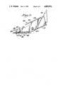
- FIG. 1is a side elevational view of a surgical staple remover according to the present invention, the remover being in its open position;
- FIG. 2is an enlarged fragmental top plan view of the surgical staple remover of FIG. 1 with a staple positioned on the anvil sections and a smaller staple illustrated in phantom outline;
- FIG. 3is an enlarged front end elevational view of the surgical staple remover shown in FIG. 1;
- FIG. 4is an enlarged side elevational view of the surgical staple remover shown in FIG. 1 with the curved blade thereof also shown in phantom outline at its initial point of contact with a staple;
- FIG. 5is an enlarged side elevational view similar to FIG. 4 illustrating the blade section in its fully closed position and the staple removed.
- the various figuresillustrate a surgical staple remover 10 for extracting a staple 12 from the skin 14 of a patient.
- the remover 10comprises a first handle element 16 having a rear portion 18 and a front portion 20 terminating in a pair of outwardly extending anvil sections 22,24.
- portions of the anvil sections 22,24have outside surfaces 28,30 that diverge away from each other in the front to rear direction for the purpose of accommodating different size staples on the anvil sections, as explained more fully below.
- the surgical staple remover 10also includes a second handle element 32 having a rear portion 34 and a front portion 36 provided with a blade section 38 constructed and arranged for movement toward and away from the anvil sections 22,24 and into and out of the slotted opening 26 therebetween.
- the blade section 38has a lower concavely curved staple engaging edge 40 as shown best in FIGS. 4 and 5.
- a pivot in the form of a rivet 42connects together the first and second handle elements 16,32 which enables the concavely curved edge 40 of the blade section 38 to move toward the anvil sections 22,24 and through the slotted opening 26 when the rear portions 18,34 of the handle elements 16,32 are moved toward each other.
- Such actioncauses the curved edge 40 to engage the staple 12 positioned on the anvil sections 22,24 with a downward and rearward force to thereby produce a U-shaped bend in the crown 44 of the staple 12 as is known in the art and partially shown in FIG. 5.
- the outwardly extending anvil sections 22,24 of the surgical staple remover 10are preferably disposed in a plane, perpendicular to the plane of handle elements 16,32, and the pivot point or rivet 42 is positioned rearward of the anvil sections 22,24 but relatively close to the plane thereof.
- the rivet 42located close to the plane of the anvil sections 22,24, minimal sliding action occurs between the concavely curved blade edge 40 and the crown 44 of the staple 12 during the crimping and removal operation. Since the effect of sliding contact between the blade 38 and the staple 12 tends to spin the staple outwardly, minimizing such sliding action produces the beneficial result of minimizing any tendency for the staple to so spin.
- Spinning of the staple 12 during the extraction processis also eliminated by the force generated by the concavely curved blade edge 40 when it engages the staple crown 44.
- the staple 12positively positioned on the anvil sections 22,24 and the side portions of L-shaped legs 46 of the staple 12 positively engaging the diverging outside surfaces 28,30, further rearward movement of the staple 12 on the anvil sections 22,24 is impossible.
- the concavely curved blade surface 40produces a force on the staple crown 44 which is both downward and rearward, the staple 12 is crimped without any forward or rearward movement on the anvil sections 22,24.
- the blade 38produces a U-shaped bend in the crown 44 of the staple 12 which causes the L-shaped legs 46 to lift upwardly and outwardly away from the patient's skin 14.
- the most forward portions of the anvil sections 22,24contact each other to thereby form a closed and narrow front tip 48.
- the closed tip 48facilitates insertion of the anvil sections 22,24 under the crown 44 of a staple 12 to be removed.
- the front portion 20 of the first handle element 16is bifurcated, thereby forming an inverted U-shaped section 50 with the anvil sections 22,24 extending outwardly from the lower extremes of that section 50.
- the most forward portion of each side of the inverted U-shaped section 50defines an upstanding wall 52 immediately rearward of the diverging anvil sections 22,24 but forward of the pivot 42.
- Each wall 52functions to limit rearward movement of a stale 12 positioned on the anvil sections 22,24, in those instances where the staple crown 44 is somewhat wider than the widest span of the diverging outside surfaces 28,30 of the anvil sections 22,24. Under these conditions, the L-shaped legs 46 of such a staple will not engage the outside surfaces 28,30, but rearward movement of the staple 12 is prevented by contact with the upstanding walls 52.
- each of the first and second handle elements 16,32has a finger-receiving ring 54,56 to facilitate manipulation of the remover.
- This arrangementfunctions to lessen the danger of finger slippage when compared to pliers-type devices.
- at least the inside surface of each finger-receiving ring 54,56includes a soft liner 58 fabricated, for example, from thermoplastic material.
- the surgical staple remover 10 of the present inventionmay be made of stainless steel or the like, fabricated by stamping or other techniques known in the art. When made of such materials, the remover may be sterilized and reused. However, the remover may be made as a single-use, disposable item from any suitable noncorrosive material such as synthetic plastic and the like.
- the surgical staple remover 10is quite simple but extremely effective in the removal of staples 12 from the skin 14 of a patient.
- the first and second handle elements 16,32are spread apart at the rear portions 18,34 thereof until the blade section 38 engages the bight of the inverted U-shaped section 50, as is clear from FIG. 4.
- the front tip 48 of the remover 10is inserted under the staple crown 44 until the legs 46 of the staple 12 engage the outside diverging surfaces 28,30 of the anvil sections 22,24.
- the finger-receiving rings 54,56are moved together causing the concavely curved edge 40 of the blade section 38 to engage the crown 44 of the staple 12.
Landscapes
- Health & Medical Sciences (AREA)
- Surgery (AREA)
- Life Sciences & Earth Sciences (AREA)
- Engineering & Computer Science (AREA)
- Molecular Biology (AREA)
- Public Health (AREA)
- Heart & Thoracic Surgery (AREA)
- Medical Informatics (AREA)
- Nuclear Medicine, Radiotherapy & Molecular Imaging (AREA)
- Animal Behavior & Ethology (AREA)
- General Health & Medical Sciences (AREA)
- Biomedical Technology (AREA)
- Veterinary Medicine (AREA)
- Mechanical Engineering (AREA)
- Surgical Instruments (AREA)
- Materials For Medical Uses (AREA)
- Control And Other Processes For Unpacking Of Materials (AREA)
- Pharmaceuticals Containing Other Organic And Inorganic Compounds (AREA)
Abstract
Description
Claims (8)
Priority Applications (11)
| Application Number | Priority Date | Filing Date | Title |
|---|---|---|---|
| US06/456,160US4805876A (en) | 1983-01-06 | 1983-01-06 | Surgical staple remover |
| EP83307667AEP0115147B1 (en) | 1983-01-06 | 1983-12-16 | Surgical staple remover |
| DE8383307667TDE3372165D1 (en) | 1983-01-06 | 1983-12-16 | Surgical staple remover |
| AT83307667TATE27899T1 (en) | 1983-01-06 | 1983-12-16 | SURGICAL DESTAPLING FORCEPS. |
| KR1019830006221AKR860001796B1 (en) | 1983-01-06 | 1983-12-27 | Surgical Staple Remover |
| JP58252407AJPS59137042A (en) | 1983-01-06 | 1983-12-29 | Surgical staple pulling device |
| CA000444667ACA1228065A (en) | 1983-01-06 | 1984-01-04 | Surgical staple remover |
| ES528689AES528689A0 (en) | 1983-01-06 | 1984-01-04 | SURGICAL STAPLES EXTRACTOR |
| DK003784ADK163140C (en) | 1983-01-06 | 1984-01-05 | DEVICE FOR SURGICAL PAPER REMOVAL |
| ZA8477AZA8477B (en) | 1983-01-06 | 1984-01-05 | Surgical staple remover |
| MX199968AMX154387A (en) | 1983-01-06 | 1984-01-05 | IMPROVEMENTS TO SURGICAL STAPLES EXTRACTOR |
Applications Claiming Priority (1)
| Application Number | Priority Date | Filing Date | Title |
|---|---|---|---|
| US06/456,160US4805876A (en) | 1983-01-06 | 1983-01-06 | Surgical staple remover |
Publications (1)
| Publication Number | Publication Date |
|---|---|
| US4805876Atrue US4805876A (en) | 1989-02-21 |
Family
ID=23811689
Family Applications (1)
| Application Number | Title | Priority Date | Filing Date |
|---|---|---|---|
| US06/456,160Expired - LifetimeUS4805876A (en) | 1983-01-06 | 1983-01-06 | Surgical staple remover |
Country Status (11)
| Country | Link |
|---|---|
| US (1) | US4805876A (en) |
| EP (1) | EP0115147B1 (en) |
| JP (1) | JPS59137042A (en) |
| KR (1) | KR860001796B1 (en) |
| AT (1) | ATE27899T1 (en) |
| CA (1) | CA1228065A (en) |
| DE (1) | DE3372165D1 (en) |
| DK (1) | DK163140C (en) |
| ES (1) | ES528689A0 (en) |
| MX (1) | MX154387A (en) |
| ZA (1) | ZA8477B (en) |
Cited By (16)
| Publication number | Priority date | Publication date | Assignee | Title |
|---|---|---|---|---|
| US5088692A (en)* | 1990-09-04 | 1992-02-18 | Weiler Raywood C | Heavy duty staple remover |
| US5236435A (en)* | 1991-07-22 | 1993-08-17 | Sewell Jr Frank | Laparoscopic surgical staple system |
| US5334196A (en)* | 1992-10-05 | 1994-08-02 | United States Surgical Corporation | Endoscopic fastener remover |
| US5380339A (en)* | 1992-03-20 | 1995-01-10 | Webster; Robert M. | Parasite remover |
| US5438759A (en)* | 1994-05-24 | 1995-08-08 | Dieringer; Janice A. | Button removal device |
| US5451231A (en)* | 1994-03-11 | 1995-09-19 | Ryder International Corporation | Surgical staple remover |
| US5605320A (en)* | 1995-01-18 | 1997-02-25 | Xerox Corporation | Staple removers |
| USD438965S1 (en) | 1999-10-25 | 2001-03-13 | Kencap Ltd. | Surgical staple remover |
| US20050262704A1 (en)* | 2004-05-28 | 2005-12-01 | Disanto Daniel M | Handheld seam ripper apparatus |
| US20110224694A1 (en)* | 2010-03-10 | 2011-09-15 | Mijares Michael J | Surgical staple remover |
| USD648196S1 (en)* | 2010-09-13 | 2011-11-08 | B.H.P. Industries Co., Ltd. | Staple remover |
| US20110319914A1 (en)* | 2010-03-10 | 2011-12-29 | Mark Sinnreich | Surgical staple remover |
| US8579917B1 (en) | 2013-02-18 | 2013-11-12 | Sinn Rx, LLC | Surgical staple remover with removable front end |
| US8591524B1 (en) | 2013-03-25 | 2013-11-26 | Sinn Rx, LLC | Surgical staple remover with channel guided movement |
| US8617182B1 (en) | 2013-02-18 | 2013-12-31 | Sinn Rx, LLC | Surgical staple remover |
| US8690896B1 (en) | 2013-03-25 | 2014-04-08 | Sinn Rx, LLC | Surgical staple remover with spring loaded movement |
Families Citing this family (3)
| Publication number | Priority date | Publication date | Assignee | Title |
|---|---|---|---|---|
| US4903945A (en)* | 1988-03-25 | 1990-02-27 | Wang Yun L | Staple remover |
| KR20010054820A (en)* | 1999-12-08 | 2001-07-02 | 김상일 | Surgical staple remover |
| US6845734B2 (en) | 2002-04-11 | 2005-01-25 | Micron Technology, Inc. | Deposition apparatuses configured for utilizing phased microwave radiation |
Citations (3)
| Publication number | Priority date | Publication date | Assignee | Title |
|---|---|---|---|---|
| US923734A (en)* | 1908-05-15 | 1909-06-01 | Chloa W Tindall | Handle for shears or scissors. |
| US2079672A (en)* | 1934-12-28 | 1937-05-11 | Boston Wire Stitcher Co | Staple-extractor |
| US4026520A (en)* | 1976-03-05 | 1977-05-31 | Senco Products, Inc. | Surgical staple extractor |
Family Cites Families (4)
| Publication number | Priority date | Publication date | Assignee | Title |
|---|---|---|---|---|
| US2202984A (en)* | 1939-03-17 | 1940-06-04 | Lou Obstfeld | Staple remover |
| US3162423A (en)* | 1962-12-07 | 1964-12-22 | James A Hall | Staple puller |
| EP0059778A1 (en)* | 1981-03-09 | 1982-09-15 | American Cyanamid Company | Staple extracting instrument |
| US4685460A (en)* | 1981-08-10 | 1987-08-11 | Edward Weck & Company, Inc. | Skin clip remover |
- 1983
- 1983-01-06USUS06/456,160patent/US4805876A/ennot_activeExpired - Lifetime
- 1983-12-16ATAT83307667Tpatent/ATE27899T1/ennot_activeIP Right Cessation
- 1983-12-16EPEP83307667Apatent/EP0115147B1/ennot_activeExpired
- 1983-12-16DEDE8383307667Tpatent/DE3372165D1/ennot_activeExpired
- 1983-12-27KRKR1019830006221Apatent/KR860001796B1/ennot_activeExpired
- 1983-12-29JPJP58252407Apatent/JPS59137042A/enactiveGranted
- 1984
- 1984-01-04CACA000444667Apatent/CA1228065A/ennot_activeExpired
- 1984-01-04ESES528689Apatent/ES528689A0/enactiveGranted
- 1984-01-05DKDK003784Apatent/DK163140C/ennot_activeIP Right Cessation
- 1984-01-05ZAZA8477Apatent/ZA8477B/enunknown
- 1984-01-05MXMX199968Apatent/MX154387A/enunknown
Patent Citations (3)
| Publication number | Priority date | Publication date | Assignee | Title |
|---|---|---|---|---|
| US923734A (en)* | 1908-05-15 | 1909-06-01 | Chloa W Tindall | Handle for shears or scissors. |
| US2079672A (en)* | 1934-12-28 | 1937-05-11 | Boston Wire Stitcher Co | Staple-extractor |
| US4026520A (en)* | 1976-03-05 | 1977-05-31 | Senco Products, Inc. | Surgical staple extractor |
Cited By (19)
| Publication number | Priority date | Publication date | Assignee | Title |
|---|---|---|---|---|
| US5088692A (en)* | 1990-09-04 | 1992-02-18 | Weiler Raywood C | Heavy duty staple remover |
| US5236435A (en)* | 1991-07-22 | 1993-08-17 | Sewell Jr Frank | Laparoscopic surgical staple system |
| US5364406A (en)* | 1991-07-22 | 1994-11-15 | Sewell Jr Frank | Laparoscopic surgical staple |
| US5380339A (en)* | 1992-03-20 | 1995-01-10 | Webster; Robert M. | Parasite remover |
| US5334196A (en)* | 1992-10-05 | 1994-08-02 | United States Surgical Corporation | Endoscopic fastener remover |
| US5451231A (en)* | 1994-03-11 | 1995-09-19 | Ryder International Corporation | Surgical staple remover |
| US5438759A (en)* | 1994-05-24 | 1995-08-08 | Dieringer; Janice A. | Button removal device |
| US5605320A (en)* | 1995-01-18 | 1997-02-25 | Xerox Corporation | Staple removers |
| USD438965S1 (en) | 1999-10-25 | 2001-03-13 | Kencap Ltd. | Surgical staple remover |
| US20050262704A1 (en)* | 2004-05-28 | 2005-12-01 | Disanto Daniel M | Handheld seam ripper apparatus |
| US20110224694A1 (en)* | 2010-03-10 | 2011-09-15 | Mijares Michael J | Surgical staple remover |
| US20110319914A1 (en)* | 2010-03-10 | 2011-12-29 | Mark Sinnreich | Surgical staple remover |
| US8177793B2 (en) | 2010-03-10 | 2012-05-15 | Sinn Rx, LLC | Surgical staple remover |
| US8241303B2 (en)* | 2010-03-10 | 2012-08-14 | Sinn Rx, LLC | Surgical staple remover |
| USD648196S1 (en)* | 2010-09-13 | 2011-11-08 | B.H.P. Industries Co., Ltd. | Staple remover |
| US8579917B1 (en) | 2013-02-18 | 2013-11-12 | Sinn Rx, LLC | Surgical staple remover with removable front end |
| US8617182B1 (en) | 2013-02-18 | 2013-12-31 | Sinn Rx, LLC | Surgical staple remover |
| US8591524B1 (en) | 2013-03-25 | 2013-11-26 | Sinn Rx, LLC | Surgical staple remover with channel guided movement |
| US8690896B1 (en) | 2013-03-25 | 2014-04-08 | Sinn Rx, LLC | Surgical staple remover with spring loaded movement |
Also Published As
| Publication number | Publication date |
|---|---|
| DK163140C (en) | 1992-06-22 |
| DK3784D0 (en) | 1984-01-05 |
| ES8500040A1 (en) | 1984-10-01 |
| DK3784A (en) | 1984-07-07 |
| JPS6315853B2 (en) | 1988-04-06 |
| EP0115147A1 (en) | 1984-08-08 |
| DE3372165D1 (en) | 1987-07-30 |
| JPS59137042A (en) | 1984-08-06 |
| EP0115147B1 (en) | 1987-06-24 |
| DK163140B (en) | 1992-01-27 |
| ES528689A0 (en) | 1984-10-01 |
| KR840007349A (en) | 1984-12-07 |
| MX154387A (en) | 1987-08-04 |
| CA1228065A (en) | 1987-10-13 |
| ATE27899T1 (en) | 1987-07-15 |
| KR860001796B1 (en) | 1986-10-23 |
| ZA8477B (en) | 1984-08-29 |
Similar Documents
| Publication | Publication Date | Title |
|---|---|---|
| US4805876A (en) | Surgical staple remover | |
| US4026520A (en) | Surgical staple extractor | |
| US4487394A (en) | Extractor for surgical staples | |
| US4685460A (en) | Skin clip remover | |
| US4802478A (en) | Medical staple and removal method | |
| US4246698A (en) | Suture remover | |
| US5591178A (en) | Surgical clip applier | |
| US4217902A (en) | Hemostatic clip | |
| US5085404A (en) | Staple removing device | |
| JPS6134813B2 (en) | ||
| JPH0341169B2 (en) | ||
| US5090663A (en) | Staple remover | |
| WO2006077878A1 (en) | Staple for medical treatment | |
| US4565199A (en) | Ligator | |
| US4895289A (en) | Ophthalmic stapler | |
| US5605320A (en) | Staple removers | |
| US6740099B1 (en) | Surgical tool for trimming wire strands | |
| US4515348A (en) | Skin staple extractor | |
| EP0253629A1 (en) | Staple | |
| US5524866A (en) | Staple remover | |
| CA1192466A (en) | Extractor for surgical staples | |
| US11045936B2 (en) | Staple remover | |
| KR20010054820A (en) | Surgical staple remover | |
| JPH0646875U (en) | Stapler needle remover | |
| JPH01289675A (en) | Staple detaching tool |
Legal Events
| Date | Code | Title | Description |
|---|---|---|---|
| AS | Assignment | Owner name:BLAKE, JOSEPH W. III, 88 MAIN ST. NEW CANAAN, CT. Free format text:ASSIGNMENT OF ASSIGNORS INTEREST.;ASSIGNORS:BLAKE, JOSEPH W. III;DI CESARE, PAUL C.;REEL/FRAME:004082/0298 Effective date:19821220 Owner name:KAUFMAN, JACK W., 357 FRANKEL BLVD. MERRICK, N.Y. Free format text:ASSIGNMENT OF ASSIGNORS INTEREST.;ASSIGNORS:BLAKE, JOSEPH W. III;DI CESARE, PAUL C.;REEL/FRAME:004082/0298 Effective date:19821220 | |
| FEPP | Fee payment procedure | Free format text:PAYOR NUMBER ASSIGNED (ORIGINAL EVENT CODE: ASPN); ENTITY STATUS OF PATENT OWNER: LARGE ENTITY | |
| STCF | Information on status: patent grant | Free format text:PATENTED CASE | |
| FEPP | Fee payment procedure | Free format text:PAYER NUMBER DE-ASSIGNED (ORIGINAL EVENT CODE: RMPN); ENTITY STATUS OF PATENT OWNER: LARGE ENTITY | |
| FEPP | Fee payment procedure | Free format text:PAYOR NUMBER ASSIGNED (ORIGINAL EVENT CODE: ASPN); ENTITY STATUS OF PATENT OWNER: LARGE ENTITY | |
| FPAY | Fee payment | Year of fee payment:4 | |
| FPAY | Fee payment | Year of fee payment:8 | |
| REMI | Maintenance fee reminder mailed | ||
| FPAY | Fee payment | Year of fee payment:12 | |
| SULP | Surcharge for late payment | ||
| AS | Assignment | Owner name:TELEFLEX-CT DEVICES INCORPORATED, PENNSYLVANIA Free format text:ASSIGNMENT OF ASSIGNORS INTEREST;ASSIGNOR:GENZYME CORPORATION;REEL/FRAME:014363/0776 Effective date:20030630 Owner name:TELEFLEX-CT DEVICES INCORPORATED,PENNSYLVANIA Free format text:ASSIGNMENT OF ASSIGNORS INTEREST;ASSIGNOR:GENZYME CORPORATION;REEL/FRAME:014363/0776 Effective date:20030630 | |
| AS | Assignment | Owner name:TECHNOLOGY HOLDING COMPANY II, DELAWARE Free format text:ASSIGNMENT OF ASSIGNORS INTEREST;ASSIGNOR:TELEFLEX-CT DEVICES INCORPORATED;REEL/FRAME:016059/0332 Effective date:20031217 |