US4805697A - Method of pumping hydrocarbons from a mixture of said hydrocarbons with an aqueous phase and installation for the carrying out of the method - Google Patents
Method of pumping hydrocarbons from a mixture of said hydrocarbons with an aqueous phase and installation for the carrying out of the methodDownload PDFInfo
- Publication number
- US4805697A US4805697AUS07/092,172US9217287AUS4805697AUS 4805697 AUS4805697 AUS 4805697AUS 9217287 AUS9217287 AUS 9217287AUS 4805697 AUS4805697 AUS 4805697A
- Authority
- US
- United States
- Prior art keywords
- fact
- centrifugal
- hydrocarbons
- separator
- pump
- Prior art date
- Legal status (The legal status is an assumption and is not a legal conclusion. Google has not performed a legal analysis and makes no representation as to the accuracy of the status listed.)
- Expired - Lifetime
Links
- 238000009434installationMethods0.000titleclaimsabstractdescription53
- 229930195733hydrocarbonNatural products0.000titleclaimsabstractdescription48
- 150000002430hydrocarbonsChemical class0.000titleclaimsabstractdescription48
- 239000008346aqueous phaseSubstances0.000titleclaimsabstractdescription34
- 239000000203mixtureSubstances0.000titleclaimsabstractdescription30
- 238000000034methodMethods0.000titleclaimsabstractdescription13
- 238000005086pumpingMethods0.000titleclaimsdescription5
- 238000004519manufacturing processMethods0.000claimsabstractdescription21
- 230000001105regulatory effectEffects0.000claimsabstractdescription12
- 239000012071phaseSubstances0.000claimsdescription16
- 230000003068static effectEffects0.000claimsdescription15
- 239000004215Carbon black (E152)Substances0.000claimsdescription11
- 238000004891communicationMethods0.000claimsdescription7
- 230000004913activationEffects0.000claimsdescription6
- 230000005484gravityEffects0.000claimsdescription4
- 238000012544monitoring processMethods0.000claimsdescription4
- 238000011084recoveryMethods0.000claimsdescription2
- 238000000926separation methodMethods0.000abstractdescription7
- XLYOFNOQVPJJNP-UHFFFAOYSA-NwaterSubstancesOXLYOFNOQVPJJNP-UHFFFAOYSA-N0.000description27
- 230000000694effectsEffects0.000description5
- 239000012528membraneSubstances0.000description4
- 239000012530fluidSubstances0.000description3
- 230000003213activating effectEffects0.000description2
- 230000005540biological transmissionEffects0.000description2
- 238000001514detection methodMethods0.000description2
- 230000000295complement effectEffects0.000description1
- 230000001276controlling effectEffects0.000description1
- 230000005611electricityEffects0.000description1
- 239000000839emulsionSubstances0.000description1
- 238000000605extractionMethods0.000description1
- 238000012856packingMethods0.000description1
- 230000000149penetrating effectEffects0.000description1
- 238000007789sealingMethods0.000description1
- 238000011144upstream manufacturingMethods0.000description1
Images


Classifications
- E—FIXED CONSTRUCTIONS
- E21—EARTH OR ROCK DRILLING; MINING
- E21B—EARTH OR ROCK DRILLING; OBTAINING OIL, GAS, WATER, SOLUBLE OR MELTABLE MATERIALS OR A SLURRY OF MINERALS FROM WELLS
- E21B43/00—Methods or apparatus for obtaining oil, gas, water, soluble or meltable materials or a slurry of minerals from wells
- E21B43/34—Arrangements for separating materials produced by the well
- E21B43/38—Arrangements for separating materials produced by the well in the well
- E21B43/385—Arrangements for separating materials produced by the well in the well by reinjecting the separated materials into an earth formation in the same well
Definitions
- the present inventionconcerns a method and an installation for the production of hydrocarbons from a mixture of said hydrocarbons with water, by which method this mixture is separated into an aqueous phase containing essentially water in free state, that is to say water that is not in the condition of an emulsion, and a light phase consisting essentially of hydrocarbons, this light phase possibly containing a certain proportion of emulsified water.
- the inventiontherefore, concerns the production of hydrocarbons and the removal of the water possibly present in these hydrocarbons for its reinjection in the vicinity of the producing zone, whether this reinjection is effected above the producing zone or below it.
- This installationmakes it necessary to have production casings of large diameter, and it, therefore, is poorly compatible with the existing production casings. Furthermore, this installation does not permit monitoring of the reinjected aqueous phase; in particular, it does not make it possible to verify that the aqueous phase does not contain hydrocarbons.
- One of the main purposes of the inventionis to propose a method which permits monitoring of the reinjected aqueous phase in the vicinity of the producing zone.
- the inventionprovides a method of pumping hydrocarbons from a mixture of these hydrocarbons with an aqueous phase, said mixture being contained in a producing zone, this method providing a step of separating the mixture into an aqueous phase and a light phase containing essentially hydrocarbons, reinjecting of the aqueous phase into a reinjection zone, said reinjection taking place in accordance with a rate of flow which is regulated as a function of the content of light phase present in the aqueous phase which can be contained within said aqueous phase.
- a second purpose of the inventionis to provide an installation for the carrying out of this method, which is compact and can be easily arranged in existing production wells. This purpose is achieved in the manner that the installation according to the invention is a pumping installation which is located at the lower end of the production well and comprises:
- a reinjection meanscomprising a centrifugal pump for reinjecting the aqueous phase into the reinjection zone at a predetermined rate of flow
- a regulating meansfor regulating said rate of flow as a function of the hydrocarbon content of the reinjected aqueous phase.
- the reinjection meanspreferably comprises a valve, the opening of which is controlled by said regulating means.
- This valveis preferably connected to the pump by a tube in which there is contained a means of monitoring the hydrocarbon content of the aqueous phase.
- the separating means and the centrifugal pumpare located in the same cylindrical enclosure and the separating means comprises an aqueous phase recovery chamber which is in direct communication with a suction chamber of the centrifugal pump.
- the separating meanscan consist of a centrifugal separator. That is to say, a separator, which imparts to the mixture a tangential velocity sufficient to permit the separation of the aqueous phase from the light phase.
- a centrifugal separatormay be a dynamic centrifugal separator in which the kinetic energy is due to the action of the rotor (or impeller), which is movable in rotation.
- a centrifugal separatorcan also be a static centrifugal separator in which the kinetic energy imparted to the mixture is due to the passage of the mixture over a static helicoidal deflector under the effect either of the reinjection pump or of the potential of the producing zone.
- the rotor of the separatoris driven in rotation by the same means as the means for the rotor of the centrifugal reinjection pump.
- the installationcomprises a buffer chamber located above the separator and intended to assure additional separation by gravity and to make the treatment rate of the aqueous phase coming from the centrifugal separator uniform.
- the aqueous phasecomes to rest and is thus subjected to a secondary separation by gravity.
- This chamberis preferably provided with a water-hydrocarbon interface detector which controls the placing of the production string in communication with the upper part of the buffer chamber so as to evacuate the hydrocarbons at the top of the buffer chamber.
- the length of this chamberis variable and is determined as a function of the nature of the mixture and its rate of flow.
- the separatoris a dynamic centrifugal separator located above the centrifugal reinjection pump, and it comprises a cylindrical wall co-axial to the said enclosure which defines with it an annular chamber which constitutes the suction chamber of the pump.
- Such an installationpreferably comprises a buffer chamber above the separator.
- This installationmay, if necessary, have a second centrifugal pump which constitutes an activating pump for the light phase.
- the installationcomprises means for the introduction of the mixture of the two phases into the separator.
- FIG. 1shows a hydrocarbon production well having an installation in accordance with the invention
- FIG. 2shows an installation according to the invention which is intended for an eruptive well
- FIG. 3shows an installation similar to that of FIG. 2, but intended for a non-eruptive well
- FIG. 4shows an installation according to the invention, provided with a static separator
- FIG. 5shows another variant of the invention in accordance with which the installation has a static separator
- FIG. 6is a section along the axis VI--VI of FIG. 5;
- FIG. 7is a view of an installation according to the invention the driving power of which is obtained from a hydraulic motor
- FIG. 8shows another embodiment according to the invention.
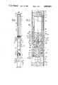
- FIG. 1shows a hydrocarbon production well having an installation in accordance with the invention and permitting the reinjection of the separated water at a level below the level of the producing zone.
- the production installationcomprises a casing 1 which extends from the surface of the ground to the reinjection zone 2.
- the installation 3 of the inventionis located at the level of the producing zone 4 between the annular sealing packings 5 and 6 known to those skilled in the art as "packers". It comprises a reinjection pump 7, a separator 8, an activation pump 9, and an electric motor 10 which permits the driving of the activation pump 9, of the rotor of the separator 8, and of the reinjection pump 7.
- the motor 10is fed with electricity from the surface by the cable 11; the installation 3 is connected to the surface by the production tube 12 which are firmly attached to the wellhead 13.
- the reinjection pump 7debouches towards the reinjection zone 2 via a reinjection tube 14, the regulated valve 15 and detectors 16.
- the well casing 1is provided at the level of the producing zone 4 with entrance orifices such as 20 and at the level of the reinjection zone 2 with reinjection orifices such as 21.
- FIG. 2shows a detail view of an installation 3 intended for an eruptive well.
- the separator 8has a helicoidal impeller 25 with three stages 26, 27, 28 and a stator 29 formed of a divergent part 30, a convergent part 31 and the circular wall 32.
- the helicoidal impelleris driven in rotation by the electric motor 10 via the transmission shaft 35.
- the circular wall 40 of the enclosure 41defines, with the circular wall 32 of the separator 8, an annular chamber 40 the role of which will be defined further below.
- the separator 8comprises a deflector wall 200, which has an entrance zone 201 which is circular and surrounds the transmission shaft 35.
- the entrance zone 201is connected to the enclosure 41 by a convergent wall 202 which defines a passage 203. This passage debouches into the annular space 204 defined by the wall of the motor 10 and the wall 40 of the enclosure 41.
- the reinjection pump 7Within the enclosure 41 and below the separator there is the reinjection pump 7. It comprises a multi-stage stator 47 and a motor 48 formed of vanes 49 firmly attached to the central hub 50, in its turn firmly attached to the rotation shaft 35.
- the pump 7debouches into the chamber 51 defined by the lower wall 52 of the enclosure 41, by the cylindrical wall 40 and by the disc 55 constituting the lower end of the rotor of the pump.
- This chamber 51is provided at its center with a tube 56 for the reinjection of the water, said tube, in its turn, being connected to the regulated valve 15, upstream of which the devices 16 for detecting the quality of the water are located.
- the valve 15debouches into the chamber 51 via the tube 14.
- the chamber 51is provided with perforations 21 for the reinjection.
- the enclosure 41In its upper part, the enclosure 41 is closed by the wall 70 and debouches into the production tube 12.
- the electric motor 10is located in the enclosure 41 at its upper part and is connected to its feed cable 11.
- the casing 1At the level of the producing zone 4, the casing 1 has entrance perforations 20 which debouch into the annular space defined between the casing 1 and the enclosure 41.
- This enclosure 41is provided at this production level with a tube 75 which places the annular space defined by the casing and the enclosure, on the one hand, in communication with the lower part of the separator 8, on the other hand, which part corresponds to the first stage of the impeller.
- One and the same base 80defines the lower part of the separator 8 and the upper part of the pump 7. This base also defines a communication zone 81 which places the annular zone 42 and the first suction stage of the pump in communication.
- the installation shownoperates in the following manner.
- the heavy partthat is to say the water, is drawn by the pump 7 into the chamber 81 and is delivered via the tube 56 towards the regulated valve 15 and the reinjection perforations 21.
- the group of detectors 16detects the possible presence of hydrocarbons in the water. As a function of this presence and of the quantity of hydrocarbons, the unit 16 controls the closing of the valve 15 so as to decrease the rate of flow of water to be reinjected and therefore increase the time of separation in the separator 8.
- FIG. 3shows an installation similar to that of FIG. 2 but intended for a non-eruptive well, it therefore having an activating pump 9.
- This pumpcomprises a rotor 100 and a stator 101 both of which have several stages.
- the rotor 100is integral with a central hub 102 driven in rotation by the rotation shaft 35 of the motor 10.
- the pump 9draws the hydrocarbons into the upper and central part of the separator 8 via the aspiration spout 103 which is integral with the base 105 constituting the lower part of the pump.
- the device shown in FIG. 3operates in the same manner as the one shown in FIG. 2.
- FIG. 4shows a variant embodiment of the invention in accordance with which the separator 8 is a static centrifugal separator.
- the separator 8is a static centrifugal separator.
- the parts common to the previous figuresbear the same reference numbers.
- the static separator 400has a central hub 401 having substantially the shape of an ogive, the pointed end of which is located towards the bottom of the enclosure 402 in which it is located, said ogive having a helicoidal thread 403.
- This unitis very well-known to the man skilled in the art by the name of static centrifugal separator.
- the mixture to be separatedis introduced towards the bottom of the separator and, under the effect either of the eruptive potential of the well or of the suction created by the reinjection pump, this mixture is placed in rotation by the fins.
- the hydrocarbonspenetrate into the passage 404, into the annular chamber and then into the production tubing 12.
- the aqueous phasewhich constitutes the heavy phase, is evacuated by the annular chamber 42 and then drawn in by the pump 7.
- the installation in accordance with the inventioncomprises, between the activation pump and the dynamic separator a static separator 150 comprising a central cylindrical wall 151 provided with orifices 155, a lower wall 152 and a lateral cylindrical wall 153.
- a cylindrical sleeve 164surrounds the central cylindrical wall 151 at the level of the orifices 155.
- the position of the cylindrical sleeve 164 on the cylindrical wall 151is determined by the level of the interface 165 between the hydrocarbon and the water.
- the lateral cylindrical wall 153 and the wall 41 of the enclosure 40define a crown portion closed at its ends by the two flat side walls 160 and 161.
- the lower wall 152is provided with an opening 162 which has the shape of a crown sector the angle of which is complementary to that of the crown 163. This opening 162 debouches into the upper part of the annular space 42.
- the circular wall 32is firmly attached to the bottom 170 of the separator at an angle identical to that of the chamber 162.
- FIG. 7shows an installation according to the invention in which the drive motor is a hydraulic motor, driven by a drive fluid consisting of water which is recovered at the outlet of the motor and then mixed with the aqueous phase before its reinjection into the producing zone.
- the drive motoris a hydraulic motor, driven by a drive fluid consisting of water which is recovered at the outlet of the motor and then mixed with the aqueous phase before its reinjection into the producing zone.
- the parts common to the preceding figuresbear the same reference numbers.
- the motor 250is a conventional hydraulic motor having a stator and a rotor, the said rotor being placed in rotation by a drive fluid arriving at the upper part through the channel 251.
- the fluidis collected in a casing 255 connected to an annular chamber 256 which debouches in the lower part in the annular chamber 42 defined by the wall 41 of the enclosure 40 and by the annular wall 31 of the separator 7.
- the water controlling the placing in rotation of the hydraulic motoris therefore recovered and mixed with the water coming from the dynamic centrifugal separator.
- FIG. 8shows an embodiment of the invention in accordance with which the reinjection means for the aqueous phase comprises a centrifugal pump which places the mixture to be separated in rotation and sends it to a static centrifugal separator.
- the installationis placed within the enclosure 41 located between the two packers 5 and 6. It comprises the electric motor 810 connected to the rotor 801 of the pump 800 by the shaft 802.
- the delivery chamber 803 of the pump 800is frustoconical and has a central opening 805 located opposite the end 806 of the static separator 807.
- the pump 800 and the separator 807are placed in a cylindrical enclosure 808 which, together with the wall 40 of the enclosure 41, defines the annular chamber 811 which is connected in its lower part to the tube 56.
- the enclosure 41is provided with four tubes such as 821 which place the inside of the production tubing 1 and suction chamber of the pump 800 in communication.
- the mixture of water and hydrocarbonspenetrates into the casing 1 through the orifices 20 and fills the entire space between the packers 5 and 6.
- the mixturepenetrates into the aspiration chamber of the pump 800 and it is delivered and projected onto the separator 807 in a circular movement.
- the hydrocarbonsare recovered by the production casing while the aqueous phase is recovered in the annular chamber 811 and then sent beyond the packer 6 through the tube 56.
- the inventionpermits production from a producing zone in which the mixture of hydrocarbons and water also contains a gaseous portion. Under these conditions, the gaseous portion remains mixed with the hydrocarbons and is separated out on the surface.
Landscapes
- Life Sciences & Earth Sciences (AREA)
- Engineering & Computer Science (AREA)
- Geology (AREA)
- Mining & Mineral Resources (AREA)
- Physics & Mathematics (AREA)
- Environmental & Geological Engineering (AREA)
- Fluid Mechanics (AREA)
- General Life Sciences & Earth Sciences (AREA)
- Geochemistry & Mineralogy (AREA)
- Production Of Liquid Hydrocarbon Mixture For Refining Petroleum (AREA)
- Centrifugal Separators (AREA)
- Organic Low-Molecular-Weight Compounds And Preparation Thereof (AREA)
Abstract
Description
Claims (16)
Applications Claiming Priority (2)
| Application Number | Priority Date | Filing Date | Title |
|---|---|---|---|
| FR8612341AFR2603330B1 (en) | 1986-09-02 | 1986-09-02 | PROCESS FOR PUMPING HYDROCARBONS FROM A MIXTURE OF THESE HYDROCARBONS WITH AN AQUEOUS PHASE AND INSTALLATION FOR IMPLEMENTING THE PROCESS |
| FR8612341 | 1986-09-02 |
Publications (1)
| Publication Number | Publication Date |
|---|---|
| US4805697Atrue US4805697A (en) | 1989-02-21 |
Family
ID=9338644
Family Applications (1)
| Application Number | Title | Priority Date | Filing Date |
|---|---|---|---|
| US07/092,172Expired - LifetimeUS4805697A (en) | 1986-09-02 | 1987-09-02 | Method of pumping hydrocarbons from a mixture of said hydrocarbons with an aqueous phase and installation for the carrying out of the method |
Country Status (4)
| Country | Link |
|---|---|
| US (1) | US4805697A (en) |
| FR (1) | FR2603330B1 (en) |
| GB (1) | GB2194575B (en) |
| NO (1) | NO179806C (en) |
Cited By (48)
| Publication number | Priority date | Publication date | Assignee | Title |
|---|---|---|---|---|
| US4954266A (en)* | 1988-10-03 | 1990-09-04 | Lingo Jr Lowell | Method and system for recovering free floating liquids from ground water |
| GB2248462A (en)* | 1990-10-04 | 1992-04-08 | Shell Int Research | Producing oil from a subsurface oil-containing formation layer |
| WO1994013930A1 (en)* | 1992-12-17 | 1994-06-23 | Read Process Engineering A/S | Method for cyclone separation of oil and water and means for separating of oil and water |
| US5335732A (en)* | 1992-12-29 | 1994-08-09 | Mcintyre Jack W | Oil recovery combined with injection of produced water |
| US5348420A (en)* | 1991-12-24 | 1994-09-20 | Ieg Industrie-Engineering Gmbh | Method and arrangement for influencing liquid in ground |
| US5380126A (en)* | 1992-06-03 | 1995-01-10 | Ieg Industrie-Engineering Gmbh | Method of and arrangement for rinsing out impurities from ground |
| WO1995009970A1 (en)* | 1993-10-01 | 1995-04-13 | Anil A/S | Method and apparatus for separating a well stream |
| US5474601A (en)* | 1994-08-02 | 1995-12-12 | Conoco Inc. | Integrated floating platform vertical annular separation and pumping system for production of hydrocarbons |
| AU683864B2 (en)* | 1993-02-03 | 1997-11-27 | Centre For Engineering Research Inc. | Method of reducing water in oil wells |
| US5762149A (en)* | 1995-03-27 | 1998-06-09 | Baker Hughes Incorporated | Method and apparatus for well bore construction |
| US5830368A (en)* | 1994-04-13 | 1998-11-03 | Centre For Engineering Research Inc. | Method for borehole separation of oil and water in an oil well |
| US5961841A (en)* | 1996-12-19 | 1999-10-05 | Camco International Inc. | Downhole fluid separation system |
| US5996690A (en)* | 1995-06-06 | 1999-12-07 | Baker Hughes Incorporated | Apparatus for controlling and monitoring a downhole oil/water separator |
| US6000468A (en)* | 1996-08-01 | 1999-12-14 | Camco International Inc. | Method and apparatus for the downhole metering and control of fluids produced from wells |
| US6048462A (en)* | 1997-03-14 | 2000-04-11 | Shell Oil Company | Waste component removal from crude oil or gas |
| US6068053A (en)* | 1996-11-07 | 2000-05-30 | Baker Hughes, Ltd. | Fluid separation and reinjection systems |
| US6080312A (en)* | 1996-03-11 | 2000-06-27 | Baker Hughes Limited | Downhole cyclonic separator assembly |
| US6082452A (en)* | 1996-09-27 | 2000-07-04 | Baker Hughes, Ltd. | Oil separation and pumping systems |
| US6085837A (en)* | 1998-03-19 | 2000-07-11 | Kudu Industries Inc. | Downhole fluid disposal tool and method |
| US6089317A (en)* | 1997-06-24 | 2000-07-18 | Baker Hughes, Ltd. | Cyclonic separator assembly and method |
| US6126416A (en)* | 1998-01-13 | 2000-10-03 | Camco International, Inc. | Adjustable shroud for a submergible pumping system and pumping system incorporating same |
| US6125936A (en)* | 1996-08-26 | 2000-10-03 | Swisher; Mark D. | Dual completion method for oil/gas wells to minimize water coning |
| US6131655A (en)* | 1997-02-13 | 2000-10-17 | Baker Hughes Incorporated | Apparatus and methods for downhole fluid separation and control of water production |
| US6131660A (en)* | 1997-09-23 | 2000-10-17 | Texaco Inc. | Dual injection and lifting system using rod pump and an electric submersible pump (ESP) |
| US6173774B1 (en) | 1998-07-23 | 2001-01-16 | Baker Hughes Incorporated | Inter-tandem pump intake |
| US6189613B1 (en) | 1998-09-25 | 2001-02-20 | Pan Canadian Petroleum Limited | Downhole oil/water separation system with solids separation |
| US6196312B1 (en) | 1998-04-28 | 2001-03-06 | Quinn's Oilfield Supply Ltd. | Dual pump gravity separation system |
| US6196313B1 (en) | 1997-02-12 | 2001-03-06 | Horst Simons | Method and apparatus for hydrocarbon production and reservoir water disposal |
| US6220830B1 (en)* | 1999-02-04 | 2001-04-24 | Bechtel National, Inc. | High efficiency blower and solar-powered soil remediation system |
| WO2001065064A1 (en) | 2000-03-03 | 2001-09-07 | Pancanadian Petroleum Limited | Downhole separation and injection of produced water |
| WO2001065065A1 (en) | 2000-03-03 | 2001-09-07 | Pancanadian Petroleum Limited | Downhole separation of produced water in hydrocarbon wells, and simultaneous downhole injection of separated water and surface water |
| WO2002020943A1 (en)* | 2000-09-07 | 2002-03-14 | Baker Hughes Incorporated | Electrical submersible pumps in the riser section of subsea well flowline |
| EP1191185A1 (en)* | 2000-09-26 | 2002-03-27 | Cooper Cameron Corporation | Downhole centrifugal separator and method of using same |
| US6367547B1 (en) | 1999-04-16 | 2002-04-09 | Halliburton Energy Services, Inc. | Downhole separator for use in a subterranean well and method |
| US6427774B2 (en) | 2000-02-09 | 2002-08-06 | Conoco Inc. | Process and apparatus for coupled electromagnetic and acoustic stimulation of crude oil reservoirs using pulsed power electrohydraulic and electromagnetic discharge |
| US6457522B1 (en) | 2000-06-14 | 2002-10-01 | Wood Group Esp, Inc. | Clean water injection system |
| US6457531B1 (en) | 2000-06-09 | 2002-10-01 | Wood Group Esp, Inc. | Water separation system with encapsulated electric submersible pumping device |
| US6547003B1 (en) | 2000-06-14 | 2003-04-15 | Wood Group Esp, Inc. | Downhole rotary water separation system |
| US6886636B2 (en) | 1999-05-18 | 2005-05-03 | Down Hole Injection, Inc. | Downhole fluid disposal apparatus and methods |
| US20070131429A1 (en)* | 2005-12-08 | 2007-06-14 | Vetco Gray Inc. | Subsea well separation and reinjection system |
| WO2008100592A1 (en)* | 2007-02-13 | 2008-08-21 | Saudi Arabian Oil Company | Subterannean water production, transfer and injection method and apparatus |
| US20080236821A1 (en)* | 2007-03-27 | 2008-10-02 | Schlumberger Technology Corporation | Monitoring and automatic control of operating parameters for a downhole oil/water separation system |
| US20090014171A1 (en)* | 2005-12-12 | 2009-01-15 | Shore- Tec Consult As | Method and an Apparatus for Separation and Injection of Water from a Water- and Hydrocarbon-Containing Outflow Down in a Production Well |
| US20090120638A1 (en)* | 2007-11-13 | 2009-05-14 | Baker Hughes Incorporated | Subsea well having a submersible pump assembly with a gas separator located at the pump discharge |
| US20100147511A1 (en)* | 2008-12-11 | 2010-06-17 | Schlumberger Technology Corporation | Injection well surveillance system |
| US20110056698A1 (en)* | 2009-08-18 | 2011-03-10 | Talbot Clint J | Fluid separation system for hydrocarbon wells |
| US10100624B2 (en)* | 2013-01-02 | 2018-10-16 | Schlumberger Technology Corporation | Bottom discharge electric submersible pump system and method |
| US20220268099A1 (en)* | 2021-02-25 | 2022-08-25 | Saudi Arabian Oil Company | Lifting hydrocarbons |
Families Citing this family (5)
| Publication number | Priority date | Publication date | Assignee | Title |
|---|---|---|---|---|
| US5605193A (en)* | 1995-06-30 | 1997-02-25 | Baker Hughes Incorporated | Downhole gas compressor |
| US5730871A (en)* | 1996-06-03 | 1998-03-24 | Camco International, Inc. | Downhole fluid separation system |
| US6033567A (en)* | 1996-06-03 | 2000-03-07 | Camco International, Inc. | Downhole fluid separation system incorporating a drive-through separator and method for separating wellbore fluids |
| AU6275898A (en)* | 1997-02-25 | 1998-09-09 | Baker Hughes Incorporated | Apparatus for controlling and monitoring a downhole oil/water separator |
| US7487838B2 (en)* | 2006-10-19 | 2009-02-10 | Baker Hughes Incorprated | Inverted electrical submersible pump completion to maintain fluid segregation and ensure motor cooling in dual-stream well |
Citations (7)
| Publication number | Priority date | Publication date | Assignee | Title |
|---|---|---|---|---|
| US2808111A (en)* | 1954-10-01 | 1957-10-01 | Sperry Sun Well Surveying Co | Subsurface pump |
| US3195633A (en)* | 1960-08-26 | 1965-07-20 | Charles E Jacob | Method and apparatus for producing fresh water or petroleum from underground reservoir formations without contamination of underlying heavier liquid |
| US3199592A (en)* | 1963-09-20 | 1965-08-10 | Charles E Jacob | Method and apparatus for producing fresh water or petroleum from underground reservoir formations and to prevent coning |
| US4009756A (en)* | 1975-09-24 | 1977-03-01 | Trw, Incorporated | Method and apparatus for flooding of oil-bearing formations by downward inter-zone pumping |
| US4241787A (en)* | 1979-07-06 | 1980-12-30 | Price Ernest H | Downhole separator for wells |
| US4296810A (en)* | 1980-08-01 | 1981-10-27 | Price Ernest H | Method of producing oil from a formation fluid containing both oil and water |
| US4429740A (en)* | 1981-09-03 | 1984-02-07 | The United States Of America As Represented By The United States Department Of Energy | Combination gas producing and waste-water disposal well |
Family Cites Families (3)
| Publication number | Priority date | Publication date | Assignee | Title |
|---|---|---|---|---|
| US3167125A (en)* | 1961-11-22 | 1965-01-26 | Warren P Bryan | Method for improving well production and salt water disposal |
| US3363692A (en)* | 1964-10-14 | 1968-01-16 | Phillips Petroleum Co | Method for production of fluids from a well |
| GB2194572B (en)* | 1986-08-29 | 1989-12-20 | Elf Aquitaine | A device for separating and extracting components having different densities from an effluent |
- 1986
- 1986-09-02FRFR8612341Apatent/FR2603330B1/ennot_activeExpired
- 1987
- 1987-08-19NONO873507Apatent/NO179806C/ennot_activeIP Right Cessation
- 1987-09-02GBGB8720651Apatent/GB2194575B/ennot_activeExpired - Lifetime
- 1987-09-02USUS07/092,172patent/US4805697A/ennot_activeExpired - Lifetime
Patent Citations (7)
| Publication number | Priority date | Publication date | Assignee | Title |
|---|---|---|---|---|
| US2808111A (en)* | 1954-10-01 | 1957-10-01 | Sperry Sun Well Surveying Co | Subsurface pump |
| US3195633A (en)* | 1960-08-26 | 1965-07-20 | Charles E Jacob | Method and apparatus for producing fresh water or petroleum from underground reservoir formations without contamination of underlying heavier liquid |
| US3199592A (en)* | 1963-09-20 | 1965-08-10 | Charles E Jacob | Method and apparatus for producing fresh water or petroleum from underground reservoir formations and to prevent coning |
| US4009756A (en)* | 1975-09-24 | 1977-03-01 | Trw, Incorporated | Method and apparatus for flooding of oil-bearing formations by downward inter-zone pumping |
| US4241787A (en)* | 1979-07-06 | 1980-12-30 | Price Ernest H | Downhole separator for wells |
| US4296810A (en)* | 1980-08-01 | 1981-10-27 | Price Ernest H | Method of producing oil from a formation fluid containing both oil and water |
| US4429740A (en)* | 1981-09-03 | 1984-02-07 | The United States Of America As Represented By The United States Department Of Energy | Combination gas producing and waste-water disposal well |
Cited By (71)
| Publication number | Priority date | Publication date | Assignee | Title |
|---|---|---|---|---|
| US4954266A (en)* | 1988-10-03 | 1990-09-04 | Lingo Jr Lowell | Method and system for recovering free floating liquids from ground water |
| GB2248462A (en)* | 1990-10-04 | 1992-04-08 | Shell Int Research | Producing oil from a subsurface oil-containing formation layer |
| US5348420A (en)* | 1991-12-24 | 1994-09-20 | Ieg Industrie-Engineering Gmbh | Method and arrangement for influencing liquid in ground |
| US5380126A (en)* | 1992-06-03 | 1995-01-10 | Ieg Industrie-Engineering Gmbh | Method of and arrangement for rinsing out impurities from ground |
| WO1994013930A1 (en)* | 1992-12-17 | 1994-06-23 | Read Process Engineering A/S | Method for cyclone separation of oil and water and means for separating of oil and water |
| US5711374A (en)* | 1992-12-17 | 1998-01-27 | Read Process Engineering A/S | Method for cyclone separation of oil and water and an apparatus for separating of oil and water |
| US5335732A (en)* | 1992-12-29 | 1994-08-09 | Mcintyre Jack W | Oil recovery combined with injection of produced water |
| AU683864B2 (en)* | 1993-02-03 | 1997-11-27 | Centre For Engineering Research Inc. | Method of reducing water in oil wells |
| US5860476A (en)* | 1993-10-01 | 1999-01-19 | Anil A/S | Method and apparatus for separating a well stream |
| WO1995009970A1 (en)* | 1993-10-01 | 1995-04-13 | Anil A/S | Method and apparatus for separating a well stream |
| GB2297573A (en)* | 1993-10-01 | 1996-08-07 | Anil As | Method and apparatus for separating a well stream |
| GB2297573B (en)* | 1993-10-01 | 1997-08-27 | Anil As | Method and apparatus for separating a well stream |
| US5830368A (en)* | 1994-04-13 | 1998-11-03 | Centre For Engineering Research Inc. | Method for borehole separation of oil and water in an oil well |
| US5474601A (en)* | 1994-08-02 | 1995-12-12 | Conoco Inc. | Integrated floating platform vertical annular separation and pumping system for production of hydrocarbons |
| US5762149A (en)* | 1995-03-27 | 1998-06-09 | Baker Hughes Incorporated | Method and apparatus for well bore construction |
| US5996690A (en)* | 1995-06-06 | 1999-12-07 | Baker Hughes Incorporated | Apparatus for controlling and monitoring a downhole oil/water separator |
| US6080312A (en)* | 1996-03-11 | 2000-06-27 | Baker Hughes Limited | Downhole cyclonic separator assembly |
| US6000468A (en)* | 1996-08-01 | 1999-12-14 | Camco International Inc. | Method and apparatus for the downhole metering and control of fluids produced from wells |
| US6125936A (en)* | 1996-08-26 | 2000-10-03 | Swisher; Mark D. | Dual completion method for oil/gas wells to minimize water coning |
| US6082452A (en)* | 1996-09-27 | 2000-07-04 | Baker Hughes, Ltd. | Oil separation and pumping systems |
| US6138758A (en)* | 1996-09-27 | 2000-10-31 | Baker Hughes Incorporated | Method and apparatus for downhole hydro-carbon separation |
| US6068053A (en)* | 1996-11-07 | 2000-05-30 | Baker Hughes, Ltd. | Fluid separation and reinjection systems |
| US5961841A (en)* | 1996-12-19 | 1999-10-05 | Camco International Inc. | Downhole fluid separation system |
| US6196313B1 (en) | 1997-02-12 | 2001-03-06 | Horst Simons | Method and apparatus for hydrocarbon production and reservoir water disposal |
| US6131655A (en)* | 1997-02-13 | 2000-10-17 | Baker Hughes Incorporated | Apparatus and methods for downhole fluid separation and control of water production |
| US6048462A (en)* | 1997-03-14 | 2000-04-11 | Shell Oil Company | Waste component removal from crude oil or gas |
| US6089317A (en)* | 1997-06-24 | 2000-07-18 | Baker Hughes, Ltd. | Cyclonic separator assembly and method |
| US6131660A (en)* | 1997-09-23 | 2000-10-17 | Texaco Inc. | Dual injection and lifting system using rod pump and an electric submersible pump (ESP) |
| US6126416A (en)* | 1998-01-13 | 2000-10-03 | Camco International, Inc. | Adjustable shroud for a submergible pumping system and pumping system incorporating same |
| US6085837A (en)* | 1998-03-19 | 2000-07-11 | Kudu Industries Inc. | Downhole fluid disposal tool and method |
| US6196312B1 (en) | 1998-04-28 | 2001-03-06 | Quinn's Oilfield Supply Ltd. | Dual pump gravity separation system |
| US6173774B1 (en) | 1998-07-23 | 2001-01-16 | Baker Hughes Incorporated | Inter-tandem pump intake |
| US6189613B1 (en) | 1998-09-25 | 2001-02-20 | Pan Canadian Petroleum Limited | Downhole oil/water separation system with solids separation |
| US6220830B1 (en)* | 1999-02-04 | 2001-04-24 | Bechtel National, Inc. | High efficiency blower and solar-powered soil remediation system |
| US6367547B1 (en) | 1999-04-16 | 2002-04-09 | Halliburton Energy Services, Inc. | Downhole separator for use in a subterranean well and method |
| US6886636B2 (en) | 1999-05-18 | 2005-05-03 | Down Hole Injection, Inc. | Downhole fluid disposal apparatus and methods |
| US6427774B2 (en) | 2000-02-09 | 2002-08-06 | Conoco Inc. | Process and apparatus for coupled electromagnetic and acoustic stimulation of crude oil reservoirs using pulsed power electrohydraulic and electromagnetic discharge |
| WO2001065064A1 (en) | 2000-03-03 | 2001-09-07 | Pancanadian Petroleum Limited | Downhole separation and injection of produced water |
| WO2001065065A1 (en) | 2000-03-03 | 2001-09-07 | Pancanadian Petroleum Limited | Downhole separation of produced water in hydrocarbon wells, and simultaneous downhole injection of separated water and surface water |
| US6336504B1 (en)* | 2000-03-03 | 2002-01-08 | Pancanadian Petroleum Limited | Downhole separation and injection of produced water in naturally flowing or gas-lifted hydrocarbon wells |
| US6336503B1 (en)* | 2000-03-03 | 2002-01-08 | Pancanadian Petroleum Limited | Downhole separation of produced water in hydrocarbon wells, and simultaneous downhole injection of separated water and surface water |
| US6457531B1 (en) | 2000-06-09 | 2002-10-01 | Wood Group Esp, Inc. | Water separation system with encapsulated electric submersible pumping device |
| US6547003B1 (en) | 2000-06-14 | 2003-04-15 | Wood Group Esp, Inc. | Downhole rotary water separation system |
| US6457522B1 (en) | 2000-06-14 | 2002-10-01 | Wood Group Esp, Inc. | Clean water injection system |
| WO2002020943A1 (en)* | 2000-09-07 | 2002-03-14 | Baker Hughes Incorporated | Electrical submersible pumps in the riser section of subsea well flowline |
| GB2384507A (en)* | 2000-09-07 | 2003-07-30 | Baker Hughes Inc | Electrical submersible pumps in the riser section of subsea well flowline |
| GB2384507B (en)* | 2000-09-07 | 2004-11-03 | Baker Hughes Inc | A subsea well production assembly |
| US6412562B1 (en) | 2000-09-07 | 2002-07-02 | Baker Hughes Incorporated | Electrical submersible pumps in the riser section of subsea well flowline |
| EP1191185A1 (en)* | 2000-09-26 | 2002-03-27 | Cooper Cameron Corporation | Downhole centrifugal separator and method of using same |
| US20040168572A1 (en)* | 2000-09-26 | 2004-09-02 | Cooper Cameron Corporation | Method and apparatus for separating liquid from a multi-phase liquid/gas stream |
| US6860921B2 (en) | 2000-09-26 | 2005-03-01 | Cooper Cameron Corporation | Method and apparatus for separating liquid from a multi-phase liquid/gas stream |
| NO329225B1 (en)* | 2000-09-26 | 2010-09-20 | Cooper Cameron Corp | Method and apparatus for separating liquid from a multiphase liquid / gas stream |
| US20070131429A1 (en)* | 2005-12-08 | 2007-06-14 | Vetco Gray Inc. | Subsea well separation and reinjection system |
| US7686086B2 (en)* | 2005-12-08 | 2010-03-30 | Vetco Gray Inc. | Subsea well separation and reinjection system |
| US20090014171A1 (en)* | 2005-12-12 | 2009-01-15 | Shore- Tec Consult As | Method and an Apparatus for Separation and Injection of Water from a Water- and Hydrocarbon-Containing Outflow Down in a Production Well |
| US7854261B2 (en)* | 2005-12-12 | 2010-12-21 | Shore-Tec Consult As | Method and an apparatus for separation and injection of water from a water- and hydrocarbon-containing outflow down in a production well |
| CN101903617B (en)* | 2007-02-13 | 2014-01-15 | 沙特阿拉伯石油公司 | Groundwater production, transmission and injection methods and equipment |
| US8316938B2 (en) | 2007-02-13 | 2012-11-27 | Saudi Arabian Oil Company | Subterranean water production, transfer and injection method and apparatus |
| US20100126721A1 (en)* | 2007-02-13 | 2010-05-27 | Al-Jarri Abdulrahman S | Subterranean water production, transfer and injection method and apparatus |
| CN101903617A (en)* | 2007-02-13 | 2010-12-01 | 沙特阿拉伯石油公司 | Phreatic production, transmission and injecting method and equipment |
| WO2008100592A1 (en)* | 2007-02-13 | 2008-08-21 | Saudi Arabian Oil Company | Subterannean water production, transfer and injection method and apparatus |
| US7828058B2 (en)* | 2007-03-27 | 2010-11-09 | Schlumberger Technology Corporation | Monitoring and automatic control of operating parameters for a downhole oil/water separation system |
| US20080236821A1 (en)* | 2007-03-27 | 2008-10-02 | Schlumberger Technology Corporation | Monitoring and automatic control of operating parameters for a downhole oil/water separation system |
| US7708059B2 (en)* | 2007-11-13 | 2010-05-04 | Baker Hughes Incorporated | Subsea well having a submersible pump assembly with a gas separator located at the pump discharge |
| US20090120638A1 (en)* | 2007-11-13 | 2009-05-14 | Baker Hughes Incorporated | Subsea well having a submersible pump assembly with a gas separator located at the pump discharge |
| US20100147511A1 (en)* | 2008-12-11 | 2010-06-17 | Schlumberger Technology Corporation | Injection well surveillance system |
| US8176979B2 (en)* | 2008-12-11 | 2012-05-15 | Schlumberger Technology Corporation | Injection well surveillance system |
| US20110056698A1 (en)* | 2009-08-18 | 2011-03-10 | Talbot Clint J | Fluid separation system for hydrocarbon wells |
| US10100624B2 (en)* | 2013-01-02 | 2018-10-16 | Schlumberger Technology Corporation | Bottom discharge electric submersible pump system and method |
| US20220268099A1 (en)* | 2021-02-25 | 2022-08-25 | Saudi Arabian Oil Company | Lifting hydrocarbons |
| US11578534B2 (en)* | 2021-02-25 | 2023-02-14 | Saudi Arabian Oil Company | Lifting hydrocarbons |
Also Published As
| Publication number | Publication date |
|---|---|
| GB2194575B (en) | 1990-02-21 |
| NO873507L (en) | 1988-03-03 |
| FR2603330B1 (en) | 1988-10-28 |
| GB8720651D0 (en) | 1987-10-07 |
| GB2194575A (en) | 1988-03-09 |
| NO179806C (en) | 1996-12-18 |
| NO179806B (en) | 1996-09-09 |
| FR2603330A1 (en) | 1988-03-04 |
| NO873507D0 (en) | 1987-08-19 |
Similar Documents
| Publication | Publication Date | Title |
|---|---|---|
| US4805697A (en) | Method of pumping hydrocarbons from a mixture of said hydrocarbons with an aqueous phase and installation for the carrying out of the method | |
| US8397811B2 (en) | Gas boost pump and crossover in inverted shroud | |
| CN1031898C (en) | Down-hole gas anchor device | |
| US8051907B2 (en) | Downhole separator | |
| US5755288A (en) | Downhole gas compressor | |
| US6017456A (en) | Downhole fluid separation system | |
| US6755250B2 (en) | Gas-liquid separator positionable down hole in a well bore | |
| US5762149A (en) | Method and apparatus for well bore construction | |
| CA2339510C (en) | Downhole separation of produced water in hydrocarbon wells, and simultaneous downhole injection of separated water and surface water | |
| US8196657B2 (en) | Electrical submersible pump assembly | |
| JP3377792B2 (en) | How to reduce water in oil wells | |
| US7314559B2 (en) | Separator | |
| US20100147514A1 (en) | Columnar downhole gas separator and method of use | |
| RU2201535C2 (en) | Plant to pump two-phase gas and fluid mixture out of well | |
| US20230358130A1 (en) | Stacked-helical gas separator with gas discharge outlet | |
| US11143009B1 (en) | Downhole three phase separator and method for use of same | |
| US6056054A (en) | Method and system for separating and injecting water in a wellbore | |
| WO2019023563A2 (en) | Systems, apparatuses, and methods for downhole water separation | |
| US20110024124A1 (en) | Caisson Two-Phase Emulsion Reducer | |
| US6196313B1 (en) | Method and apparatus for hydrocarbon production and reservoir water disposal | |
| US2005767A (en) | Method and apparatus for operating oil wells | |
| US4407360A (en) | Borehole water pumping system with sandtrap | |
| US6105671A (en) | Method and apparatus for minimizing emulsion formation in a pumped oil well | |
| GB2409691A (en) | Separating apparatus and method for phases of a downhole produced fluid | |
| CA1280639C (en) | Method and apparatus for pumping liquids |
Legal Events
| Date | Code | Title | Description |
|---|---|---|---|
| AS | Assignment | Owner name:SOCIETE NATIONALE ELF AQUITAINE (PRODUCTION), TOUR Free format text:ASSIGNMENT OF ASSIGNORS INTEREST.;ASSIGNORS:FOUILLOUT, CHRISTIAN;SANGO, DANIEL;REEL/FRAME:004960/0296 Effective date:19871009 Owner name:SOCIETE NATIONALE ELF AQUITAINE (PRODUCTION),FRANC Free format text:ASSIGNMENT OF ASSIGNORS INTEREST;ASSIGNORS:FOUILLOUT, CHRISTIAN;SANGO, DANIEL;REEL/FRAME:004960/0296 Effective date:19871009 | |
| AS | Assignment | Owner name:SOCIETE NATIONALE ELF AQUITAINE (PRODUCTION), TOUR Free format text:ASSIGNMENT OF ASSIGNORS INTEREST.;ASSIGNORS:FOUILLOUT, CHRISTIAN;SANGO, DANIEL;REEL/FRAME:004984/0040 Effective date:19871009 Owner name:SOCIETE NATIONALE ELF AQUITAINE (PRODUCTION), FRAN Free format text:ASSIGNMENT OF ASSIGNORS INTEREST;ASSIGNORS:FOUILLOUT, CHRISTIAN;SANGO, DANIEL;REEL/FRAME:004984/0040 Effective date:19871009 | |
| STCF | Information on status: patent grant | Free format text:PATENTED CASE | |
| FEPP | Fee payment procedure | Free format text:PAYOR NUMBER ASSIGNED (ORIGINAL EVENT CODE: ASPN); ENTITY STATUS OF PATENT OWNER: LARGE ENTITY | |
| FPAY | Fee payment | Year of fee payment:4 | |
| FPAY | Fee payment | Year of fee payment:8 | |
| FEPP | Fee payment procedure | Free format text:PAYER NUMBER DE-ASSIGNED (ORIGINAL EVENT CODE: RMPN); ENTITY STATUS OF PATENT OWNER: LARGE ENTITY Free format text:PAYOR NUMBER ASSIGNED (ORIGINAL EVENT CODE: ASPN); ENTITY STATUS OF PATENT OWNER: LARGE ENTITY | |
| FPAY | Fee payment | Year of fee payment:12 |