US4805596A - Endoscope - Google Patents
EndoscopeDownload PDFInfo
- Publication number
- US4805596A US4805596AUS07/174,116US17411688AUS4805596AUS 4805596 AUS4805596 AUS 4805596AUS 17411688 AUS17411688 AUS 17411688AUS 4805596 AUS4805596 AUS 4805596A
- Authority
- US
- United States
- Prior art keywords
- tube
- endoscope
- insertion section
- wire
- coupling
- Prior art date
- Legal status (The legal status is an assumption and is not a legal conclusion. Google has not performed a legal analysis and makes no representation as to the accuracy of the status listed.)
- Expired - Lifetime
Links
Images


Classifications
- A—HUMAN NECESSITIES
- A61—MEDICAL OR VETERINARY SCIENCE; HYGIENE
- A61B—DIAGNOSIS; SURGERY; IDENTIFICATION
- A61B1/00—Instruments for performing medical examinations of the interior of cavities or tubes of the body by visual or photographical inspection, e.g. endoscopes; Illuminating arrangements therefor
- A61B1/005—Flexible endoscopes
- A61B1/0051—Flexible endoscopes with controlled bending of insertion part
- A61B1/0055—Constructional details of insertion parts, e.g. vertebral elements
- A—HUMAN NECESSITIES
- A61—MEDICAL OR VETERINARY SCIENCE; HYGIENE
- A61B—DIAGNOSIS; SURGERY; IDENTIFICATION
- A61B1/00—Instruments for performing medical examinations of the interior of cavities or tubes of the body by visual or photographical inspection, e.g. endoscopes; Illuminating arrangements therefor
- A61B1/005—Flexible endoscopes
- A61B1/0051—Flexible endoscopes with controlled bending of insertion part
- A61B1/0057—Constructional details of force transmission elements, e.g. control wires
Definitions
- the present inventionrelates to a structure for attaching wire guides which guide operation wires incorporated in the insertion section of an endoscope and, more particularly, to an endoscope provided with an improved structure for attaching the wire guides.
- a typical endoscopeincludes an operating section, an insertion section which is inserted into a cavity of the human body, a light guide cable connected to the operating section, and a light source connector section for connecting the light guide cable to an illuminating light source means.
- Wires for causing the foremost end portion of the insertion section to bend and wire guides for guiding these wiresare arranged inside the insertion section of the endoscope.
- a typical wire guide attaching structureis disclosed in, for example, Japanese Patent Disclosure (Koki) No. 59-69024.
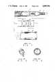
- First unit Lhas a housing which forms the distal end of the insertion section and to which are attached image and light guide fibers, an objective lens system, operating wires and so forth.
- Cap member L1mounted on the base end portion of the light guide fiber handle of first unit L, is inserted into second unit M (or bending tube having wire guide rings M1), followed by the body of first unit L.
- second unit Mor bending tube having wire guide rings M1
- third unit Nor flexible tube portion
- coating tube L2is attached round cap member L1.
- Diameter Awhich is obtained by adding the thickness of coating tube L2 to the outer diameter of cap member L1 must be made smaller than the inner diameter of the guide ring portion of the bending tube.
- itmust be made smaller than the smallest inner diameter C at coupling tube N1 where the bending and flexible tubes of the insertion section are connected to each other, particularly at that portion of the insertion section to which wire guides N2 are attached in FIG. 3. Therefore, the cap member must be smaller than the smallest inner diameter of the insertion section of the endoscope.
- Cap member L1is hard and cannot be deformed in its radial direction, but the other portion of the internal matters which is coated by coating tube L2 is soft and can be deformed in its radial direction. If the hard portion of first unit L which has diameter A can be inserted into second and third units, the insertion section can be assembled. Therefore, that portion of third unit N which has the smallest diameter C, as shown in FIG. 3, is important. As shown in FIG. 2, the foremost end of the wire guides are fitted into cut-away slits in coupling tube N1 at that portion of third unit N and fixed there by filling a bonding agent in the slit.
- the wire guidesWhen the insertion section of the endoscope which is assembled according to the above-described process is to be made still smaller in its outer diameter, the wire guides must be made still slimmer. However, they need to have such a strength that they cannot be deformed by the pulling force of the operating wire, and they must be made thick to some extent accordingly. Therefore, there is a limit in making them slimmer.
- the object of the present inventionis to provide an endoscope having an insertion section whose outer diameter can be made smaller by an improved structure for attaching wire guides which guide operating wires.
- This object of the present inventioncan be achieved by an endoscope arranged as follows:
- the endoscope according to the inventionhas an operating section and an insertion section, the body of the insertion section being constituted by a flexible tube, the foremost end thereof being a bedding tube. At least two wires for operating the bending tube from an operating section of the endoscope are each connected at one end to the bending tube, with at least two wire guides for guiding these wires being arranged in the flexible tube.
- the endoscopealso includes a coupling member for coupling the flexible and bending tubes to each other, and this coupling member includes at least two parts which can be assembled integral and to each of which is fixed one of the wire guides.
- the coupling member for coupling the flexible and bending tubes to each otheris divided to two or more parts, to each of which one of the wire guides is fixed.
- a cap member mounted on a base end portion of an optical fiber bundlecan be easily inserted into the inner hole of the coupling member even if the diameter of this inner hole of the coupling member is relatively small.
- the outer diameter of the insertion sectioncan be thus made still smaller.
- internal matterscan be filled at a higher density in the inner space of the insertion section which has a certain outer diameter. For example, the number of optical fibers which are the internal matters can be increased and an outer diameter of each of some channels for treating tools can be made larger.
- FIGS. 1 through 3are vertically-sectioned, perspective and cross-sectioned views showing the conventional endoscope
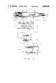
- FIG. 4is a perspective view showing the whole of an endoscope according to the present invention.
- FIG. 5is a vertically-sectioned view showing an insertion section of the first embodiment of the endoscope according to the present invention
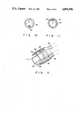
- FIG. 6is a sectional view taken along a line X--X in FIG. 5;
- FIGS. 7 and 8are perspective views showing a coupling member employed by the first embodiment of the endoscope
- FIG. 9is a sectional view showing each of units in the process of assembling the insertion section of the endoscope.
- FIG. 10is a sectional view taken along a line Y--Y in FIG. 9;
- FIG. 11is a sectional view taken along a line Z--Z in FIG. 9.
- FIG. 12is a perspective view showing a coupling member employed by a second embodiment of the endoscope according to the present invention.
- FIGS. 4 through 9show a first embodiment of the endoscope according to the present invention.
- Endoscope 1 shown in FIG. 4is provided with insertion section 2 comprising flexible tube portion 6, bending tube portion 8 and distal end member 10, and operating section 3 is conneted to the proximal end of inserted section 2.
- Light guide cable 32is connected to operating section 3 and light source connector 34 is attached to the distal end of cable 32.
- Operating section 3is also provided with eyepiece portion 5.
- flexible tube portion 6 and bending tube portion 8are connected to each other through coupling tube 4, which serves as a coupling member, at insertion section 2 of the endoscope and a distal end member or housing 10 is coupled to the distal end of bending tube portion 8.
- a plurality of tubular segments 12are arranged in a line at bending tube portion 8 and in the axial direction of bending tube portion 8 and adjacent tubular segments 12 are linked by pins 14 to be curved up and down.
- the outer circumferences of these tubular segments 12are covered by outer sheath tube 16.
- the distal end of this outer sheath tube 16is extended onto the outer circumference of the rear portion of housing 10 and fixed there by threads 18 and bonding agent 20.
- image and light guide fiber bundles 22 and 24which are inserted through insertion section 2 are attached to housing 10. More specifically, the distal end portion of image guide fiber bundle 22 is located and folded in housing 10 behind objective lens 26 by means of image guide fiber cap 28, while that of light guide fiber bundle 24 is sandwiched like a hollow cylinder between image and light guide fiber caps 28 and 30 inserted and folded in the fore of housing 10.
- Image guide fiber bundle 22 which is arranged in the hole of light guide fiber bundle 24is extended to eyepiece portion 5 in operating section 3 and its base end portion is fixed to eyepiece portion 5 by cap member 38 mounted on the base end portion.
- Light guide fiber bundle 24is extended to light source connector 34 at the foremost end of light guide cable 32, passing through operating section 3 and light guide cable 32, and its base end portion is fixed to light source connector 34 by cap member 40 mounted on base end portion.
- Image and light guide fiber bundles 22 and 24are housed in coating tube 36 at insertion section 2 but they are separated from each other and housed in different coating tubes (not shown) at operating section 3.
- Foremost tubular segment 12is coupled to the rear end portion of housing 10 which is located on the distal end portion of the endoscope, and bonded or soldered there by bonding agent or the like.
- the foremost ends of bending operation wires 42 and 44are connected to the upper and lower inner faces of foremost tubular segment 12. Bending operation wires 42 and 44 are arranged along the upper and lower inner faces of insertion section 2 and they are guided in bending tube 8 by guide rings 46 formed on the inner face of tubular segments 12, as shown in FIG. 6, while they are guided in flexible tube 6 by first and second wire guides 48 and 50.
- Coupling means 4 employed by the first embodiment of the endoscopeconsists of first connector tube 52 shown in FIG. 7 and second connector tube 54 shown in FIG. 8.
- the foremost end of first connector tube 52is provided with small-diameter portion 56 which is inserted into the inner hole of rearmost tubular segment 12 in bending tube portion 8.
- the rear end of first connector tube 52is provided with large diameter portion (or rear end portion) 60 which houses small-diameter portion (or front end portion) 58 of second connector tube 54.
- the rear end portion of second connector tube 54is provided with small diameter portion 66 which is inserted into spiral tube 62, which serves as a core member, and also into tubular braid 64.
- the intermediate portion of second connector 54is formed like ring-shaped collar 68.
- first and second connector tubes 52 and 54are coupled to each other and tubular segment 12 and first connector tube 52 are coupled to each other.
- Intermediate collar 68, rear end portion 60 of first connector tube 52 and tubular segment 12form a flat outer circumference in this case because they have same outer diameter.
- Outer sheath tube 16 of bending tube portion 8 and that of flexible tube portion 6are met each other in a ring-shaped groove formed between rear end portion 60 of first connector tube 52 and collar 68 of second connector tube 54, and they are fastened by threads 74 and then bonded there by bonding agent 76.
- First cut-away slit 78which is opened upward is formed in first connector tube 52 and partly overlapped by rearmost tubular segment 12 which is coupled to small diameter portion 56, slit 78 extending over small diameter portion 56 and rear end portion 60.
- Tubular segment 12 and connector tube 52are fixed to each other by bonding means 80 such as the bonding agent or soldering material supplying into cut-away slit 78.
- First operating wire 42is inserted into first wire guide 48 fixed to first connector tube 52, while second operating wire 44 into second wire guide 50 fixed to second connector tube 54.
- operating wires 42 and 44 in bending tube portion 8are inserted into guide rings 46 formed on the inner face of tubular segment 12 and their proximal ends are connected to a bending operation mechanism (not shown) arranged at operating section 3.
- first connector tube 52 and wire guide 48are fixedly bonded together with rearmost tubular segment 12 by filling cut-away slit 78 with fixing means 80 such as bonding agent or the like.
- Fixing means 80is filled in slit 78 in such a way that it is not projected from the outer surface of first connector tube 52.
- Second connector tube 54 and wire guide 50are connected to each other in same way as seen in the case of first connector tube 52.
- cut-away slit 82is formed in the rear portion of second connector tube 54 in the axial direction thereof and second wire guide 50 is held in cut-away slit 82 and fixedly bonded there by fixing means 84, which fills cut-away slit 82 in this case not to project from the outer surface of second connector tube 54.
- cap member 40 of first unit 7which is mounted on the base end portion of the light guide fiber bundle 24 and partly coated by coating tube 36, is inserted into bending tube 8A and the body of first unit 7 is then inserted.
- operating wires 42 and 44are also inserted into guide rings 46.
- Cap member 40 of first unit 7is inserted into first connector tube 52 which is provided with first wire guide 48.
- First operating wire 42is also inserted into first wire guide 48 this time.
- Cap member 40 mounted on the base end portion of the light guide fiber bundle 24is inserted into second unit 9 and second operating wire 44 is inserted into second wie guide 50 at the same time.
- Second unit 9includes second connector tube 54 provided with second wire guide 50, and flexible tube portion 6 previously connected to second connector tube 54.
- First and second connector tubes 52 and 54are coupled to each other after cap member 40 of first unit 7 is passed through them.
- first unit 7The internal matters such as the optical fibers which are arranged in first unit 7 from cap member 40 to the foremost end thereof are soft.
- first and second connector tubes 52 and 54When hard cap 40 of first unit 7 is passed through first and second connector tubes 52 and 54 in the process of combining first, second and third units, therefore, the inserted section can be easily assembled.
- first connector tube 52It is determined only by the inner diameter of first connector tube 52 and the outer diameter of first wire guide 48, as shown in FIG. 10, whether or not cap member 40 mounted on the base end portion of light guide fiber bundle 24 can pass through first connector tube 52. It is also determined only by the inner diameter of second connector tube 54, depth of cut-away slit 82 (or thickness of second connector tube 54) and outer diameter of second wire guide 50, as shown in FIG. 11, whether or not cap member 40 of first unit 7 can pass through second connector tube 54.
- the outer diameter of insertion section 2 of the endoscope according to the present inventionis equal to that of the insertion section of the conventional endoscope, therefore, "diameter C of a virtual circle ⁇ diameter E" and “diameter C ⁇ diameter E” will be established and the cross sectional area of the internal matters such as the optical fibers in insertion section 2 can be increased.
- outer diameter A of the internal matters of the conventional endoscopeequals to outer diameter D of that of this invention, the outer diameter of insertion section 2 can be made smaller.
- FIG. 12shows a second embodiment of the present invention.
- Coupling tube 4is divided into first and second coupling tube halves 90 and 92 in the radial direction thereof. Coupling tube 4 is formed by combining these two parts.
- First and second coupling tube halves 90 and 92are provided with cut-away slits 96 and 98, in which first and second wire guides 48 and 50 are located and fixedly bonded by fixing means 100.
- the insertion section of the second embodimentcan be assembled similarly to the case of the first embodiment. However, it is needed that first and second coupling tube halves 90 and 92 are combined with each other after cap member 40 mounted on the base end portion of the light guide fiber bundle is passed between them. It is also needed that wire guides 48 and 50 are mounted on coupling tube halves 90 and 92 by fixing means 10 to keep their inside waterproof.
- Coupling tube 4can be made shorter in the second embodiment of this invention because coupling tube 4 is divided into two parts in the radial direction thereof. Namely, the hard portion for connecting bending tube portion 8 and flexible tube portion 6 to each other can be made shorter.
- the coupling tube of the present inventionmay be applied to an endoscope wherein the number of operating wires is increased and the constitution of the bending tube is modified to bend in two or more directions. Further, the coupling tube may consist of three or more parts.
- optical fibersAlthough only the optical fibers has been shown as the internal matters in the insertion section in the case of the first and second embodiments, those channel tubes through which liquid such as medicine can be injected into the human body, dirt and the like can be sucked, and treating tools can be passed may be provided as well.
Landscapes
- Health & Medical Sciences (AREA)
- Life Sciences & Earth Sciences (AREA)
- Surgery (AREA)
- Biomedical Technology (AREA)
- Medical Informatics (AREA)
- Optics & Photonics (AREA)
- Pathology (AREA)
- Radiology & Medical Imaging (AREA)
- Biophysics (AREA)
- Engineering & Computer Science (AREA)
- Physics & Mathematics (AREA)
- Heart & Thoracic Surgery (AREA)
- Nuclear Medicine, Radiotherapy & Molecular Imaging (AREA)
- Molecular Biology (AREA)
- Animal Behavior & Ethology (AREA)
- General Health & Medical Sciences (AREA)
- Public Health (AREA)
- Veterinary Medicine (AREA)
- Endoscopes (AREA)
- Instruments For Viewing The Inside Of Hollow Bodies (AREA)
Abstract
Description
Claims (6)
Applications Claiming Priority (2)
| Application Number | Priority Date | Filing Date | Title |
|---|---|---|---|
| JP62-82626 | 1987-04-03 | ||
| JP62082626AJPH069540B2 (en) | 1987-04-03 | 1987-04-03 | Endoscope |
Publications (1)
| Publication Number | Publication Date |
|---|---|
| US4805596Atrue US4805596A (en) | 1989-02-21 |
Family
ID=13779657
Family Applications (1)
| Application Number | Title | Priority Date | Filing Date |
|---|---|---|---|
| US07/174,116Expired - LifetimeUS4805596A (en) | 1987-04-03 | 1988-03-28 | Endoscope |
Country Status (2)
| Country | Link |
|---|---|
| US (1) | US4805596A (en) |
| JP (1) | JPH069540B2 (en) |
Cited By (64)
| Publication number | Priority date | Publication date | Assignee | Title |
|---|---|---|---|---|
| EP0397489A1 (en)* | 1989-05-12 | 1990-11-14 | Kabushiki Kaisha Machida Seisakusho | Bending device and flexible tube structure |
| US4998182A (en)* | 1990-02-08 | 1991-03-05 | Welch Allyn, Inc. | Connector for optical sensor |
| US5002041A (en)* | 1989-05-12 | 1991-03-26 | Kabushiki Kaisha Machida Seisakusho | Bending device and flexible tube structure |
| US5199417A (en)* | 1990-12-21 | 1993-04-06 | Circon Corporation | Endoscope having a deflectable distal section and a semi-rigid proximal section |
| EP0535847A1 (en)* | 1991-10-04 | 1993-04-07 | Kabushiki Kaisha Machida Seisakusho | Endoscope |
| US5318526A (en)* | 1992-09-29 | 1994-06-07 | Neuro Navigational Corporation | Flexible endoscope with hypotube activating wire support |
| US5381782A (en)* | 1992-01-09 | 1995-01-17 | Spectrum Medsystems Corporation | Bi-directional and multi-directional miniscopes |
| US5591120A (en)* | 1994-11-25 | 1997-01-07 | Fuji Photo Optical Co., Ltd. | Joint construction for angle section of endoscopic insertion rod |
| US5632432A (en)* | 1994-12-19 | 1997-05-27 | Ethicon Endo-Surgery, Inc. | Surgical instrument |
| US5685825A (en)* | 1995-03-03 | 1997-11-11 | Olympus Optical Co., Ltd. | Endoscope |
| US5752644A (en)* | 1995-07-11 | 1998-05-19 | United States Surgical Corporation | Disposable loading unit for surgical stapler |
| US5928136A (en)* | 1997-02-13 | 1999-07-27 | Karl Storz Gmbh & Co. | Articulated vertebra for endoscopes and method to make it |
| US6454703B1 (en)* | 1999-09-30 | 2002-09-24 | Fuji Photo Optical Co., Ltd. | Angle portion of an endoscope |
| US20040199052A1 (en)* | 2003-04-01 | 2004-10-07 | Scimed Life Systems, Inc. | Endoscopic imaging system |
| USRE38708E1 (en) | 1995-07-11 | 2005-03-01 | United States Surgical Corporation | Disposable loading unit for surgical stapler |
| US20050168571A1 (en)* | 2004-01-29 | 2005-08-04 | Everest Vit, Inc. | Method and apparatus for improving the operation of a remote viewing device |
| US20050197536A1 (en)* | 2003-04-01 | 2005-09-08 | Banik Michael S. | Video endoscope |
| US20050222499A1 (en)* | 2003-04-01 | 2005-10-06 | Banik Michael S | Interface for video endoscope system |
| US20060068360A1 (en)* | 2004-09-30 | 2006-03-30 | Scimed Life Systems, Inc. | Single use fluid reservoir for an endoscope |
| US20060069305A1 (en)* | 2004-09-30 | 2006-03-30 | Boston Scientific Scimed, Inc. | Device with enhanced indication of use and prevention of re-use |
| US20060111613A1 (en)* | 2004-09-30 | 2006-05-25 | Boston Scientific Scimed, Inc. | Selectively rotatable shaft coupler |
| US20060114986A1 (en)* | 2004-09-30 | 2006-06-01 | Knapp Keith N Ii | Adapter for use with digital imaging medical device |
| US20060173244A1 (en)* | 2004-09-30 | 2006-08-03 | Boston Scientific Scimed, Inc. | System and method of obstruction removal |
| US20060259041A1 (en)* | 2005-05-13 | 2006-11-16 | Hoffman David W | Endoscopic apparatus with integrated variceal ligation device |
| US20060258911A1 (en)* | 2005-03-25 | 2006-11-16 | Pentax Corporation | Tightening string for an endoscope, outer cover securing method, flexible tube for an endoscope, and an endoscope |
| US20070049800A1 (en)* | 2005-08-30 | 2007-03-01 | Boston Scientific Scimed, Inc. | Method for forming an endoscope articulation joint |
| US20070225564A1 (en)* | 2006-03-27 | 2007-09-27 | Boston Scientific Scimed, Inc. | Medical devices with local drug delivery capabilities |
| US20070249907A1 (en)* | 2006-04-20 | 2007-10-25 | Boulais Dennis R | Imaging assembly with transparent distal cap |
| US20080103362A1 (en)* | 2004-09-30 | 2008-05-01 | Scimed Life Systems, Inc. | Programmable brake control system for use in a medical device |
| US7479106B2 (en) | 2004-09-30 | 2009-01-20 | Boston Scientific Scimed, Inc. | Automated control of irrigation and aspiration in a single-use endoscope |
| US7591783B2 (en) | 2003-04-01 | 2009-09-22 | Boston Scientific Scimed, Inc. | Articulation joint for video endoscope |
| US7597662B2 (en) | 2004-09-30 | 2009-10-06 | Boston Scientific Scimed, Inc. | Multi-fluid delivery system |
| US20090253958A1 (en)* | 2008-04-07 | 2009-10-08 | Olympus Corporation | Endoscope, connection method of bending section and flexible section in endoscope, production method of endoscope provided for this connection method, endoscope overtube, connection method of bending section and flexible section in endoscope overtube and production method of endoscope overtube provided for this connection method |
| US20100256448A1 (en)* | 2003-04-01 | 2010-10-07 | Boston Scientific Scimed, Inc. | Fluid manifold for endoscope system |
| US7846107B2 (en) | 2005-05-13 | 2010-12-07 | Boston Scientific Scimed, Inc. | Endoscopic apparatus with integrated multiple biopsy device |
| US7967759B2 (en) | 2006-01-19 | 2011-06-28 | Boston Scientific Scimed, Inc. | Endoscopic system with integrated patient respiratory status indicator |
| US8083671B2 (en) | 2004-09-30 | 2011-12-27 | Boston Scientific Scimed, Inc. | Fluid delivery system for use with an endoscope |
| US8118732B2 (en) | 2003-04-01 | 2012-02-21 | Boston Scientific Scimed, Inc. | Force feedback control system for video endoscope |
| US8202265B2 (en) | 2006-04-20 | 2012-06-19 | Boston Scientific Scimed, Inc. | Multiple lumen assembly for use in endoscopes or other medical devices |
| JP2012135365A (en)* | 2010-12-24 | 2012-07-19 | Olympus Corp | Endoscope |
| US20120215068A1 (en)* | 2009-11-02 | 2012-08-23 | Hoya Corporation | Method for affixing endoscope curved section protective sheath |
| US8357148B2 (en) | 2004-09-30 | 2013-01-22 | Boston Scientific Scimed, Inc. | Multi-functional endoscopic system for use in electrosurgical applications |
| US8419720B1 (en) | 2012-02-07 | 2013-04-16 | National Advanced Endoscopy Devices, Incorporated | Flexible laparoscopic device |
| US20130245376A1 (en)* | 2012-03-14 | 2013-09-19 | Fujifilm Corporation | Tube assembly for endoscope and attaching method |
| US20150265135A1 (en)* | 2011-01-19 | 2015-09-24 | Fujifilm Corporation | Endoscope |
| WO2016188537A1 (en)* | 2015-05-27 | 2016-12-01 | Ambu A/S | An endoscope |
| US10617284B2 (en) | 2015-05-27 | 2020-04-14 | Ambu A/S | Endoscope |
| US10624531B2 (en) | 2015-05-27 | 2020-04-21 | Ambu A/S | Endoscope |
| US10624617B2 (en) | 2015-05-27 | 2020-04-21 | Ambu A/S | Endoscope |
| US10631716B2 (en) | 2015-05-27 | 2020-04-28 | Ambu A/S | Endoscope |
| US10645260B2 (en) | 2015-05-27 | 2020-05-05 | Ambu A/S | Endoscope |
| US10646107B2 (en) | 2015-05-27 | 2020-05-12 | Ambu A/S | Endoscope with a tool |
| US20200268238A1 (en)* | 2018-12-21 | 2020-08-27 | Ambu A/S | Articulated tip part for an endoscope |
| CN112515613A (en)* | 2020-12-16 | 2021-03-19 | 杭州思康新医疗科技有限公司 | Endoscope device |
| US11166627B2 (en) | 2018-01-26 | 2021-11-09 | Ambu A/S | Method for fixation of a wire portion of an endoscope, and an endoscope |
| US20210386272A1 (en)* | 2019-03-11 | 2021-12-16 | Olympus Corporation | Endoscope and method for manufacturing endoscope |
| US11291352B2 (en) | 2018-03-14 | 2022-04-05 | Ambu A/S | Method for manufacturing a tip housing |
| US11291355B2 (en) | 2018-01-19 | 2022-04-05 | Ambu A/S | Method for fixation of a wire portion of an endoscope, and an endoscope |
| US11311184B2 (en) | 2018-08-24 | 2022-04-26 | Ambu A/S | Tip part for a vision device |
| US11382490B2 (en) | 2018-08-24 | 2022-07-12 | Ambu A/S | Tip part for a vision device |
| US11712151B2 (en) | 2018-08-24 | 2023-08-01 | Ambu A/S | Tip part for a vision device |
| US11944271B2 (en) | 2020-12-08 | 2024-04-02 | Ambu A/S | Endoscope tip part with improved optical properties |
| US11992181B2 (en) | 2018-12-21 | 2024-05-28 | Ambu A/S | Articulated tip part for an endoscope |
| US12016536B2 (en) | 2020-09-02 | 2024-06-25 | Ambu A/S | Endoscope tip part |
Families Citing this family (4)
| Publication number | Priority date | Publication date | Assignee | Title |
|---|---|---|---|---|
| JPH0795149B2 (en)* | 1988-10-19 | 1995-10-11 | オリンパス光学工業株式会社 | Endoscope |
| JP2593560B2 (en)* | 1988-12-26 | 1997-03-26 | オリンパス光学工業株式会社 | Endoscope |
| JP2002102150A (en)* | 2000-09-29 | 2002-04-09 | Fuji Photo Optical Co Ltd | Body cavity observation device |
| JP4932353B2 (en)* | 2006-07-10 | 2012-05-16 | オリンパスメディカルシステムズ株式会社 | Endoscope and repair method |
Citations (5)
| Publication number | Priority date | Publication date | Assignee | Title |
|---|---|---|---|---|
| US3091235A (en)* | 1960-06-15 | 1963-05-28 | American Optical Corp | Diagnostic instruments |
| US3583393A (en)* | 1967-12-26 | 1971-06-08 | Olympus Optical Co | Bendable tube assembly |
| US3788304A (en)* | 1971-06-15 | 1974-01-29 | Olympus Optical Co | Endoscope |
| US4327711A (en)* | 1979-11-16 | 1982-05-04 | Olympus Optical Co., Ltd. | Flexible tube for an endoscope |
| JPS5969024A (en)* | 1982-10-13 | 1984-04-19 | オリンパス光学工業株式会社 | Endoscope |
- 1987
- 1987-04-03JPJP62082626Apatent/JPH069540B2/ennot_activeExpired - Fee Related
- 1988
- 1988-03-28USUS07/174,116patent/US4805596A/ennot_activeExpired - Lifetime
Patent Citations (5)
| Publication number | Priority date | Publication date | Assignee | Title |
|---|---|---|---|---|
| US3091235A (en)* | 1960-06-15 | 1963-05-28 | American Optical Corp | Diagnostic instruments |
| US3583393A (en)* | 1967-12-26 | 1971-06-08 | Olympus Optical Co | Bendable tube assembly |
| US3788304A (en)* | 1971-06-15 | 1974-01-29 | Olympus Optical Co | Endoscope |
| US4327711A (en)* | 1979-11-16 | 1982-05-04 | Olympus Optical Co., Ltd. | Flexible tube for an endoscope |
| JPS5969024A (en)* | 1982-10-13 | 1984-04-19 | オリンパス光学工業株式会社 | Endoscope |
Cited By (122)
| Publication number | Priority date | Publication date | Assignee | Title |
|---|---|---|---|---|
| EP0397489A1 (en)* | 1989-05-12 | 1990-11-14 | Kabushiki Kaisha Machida Seisakusho | Bending device and flexible tube structure |
| US5002041A (en)* | 1989-05-12 | 1991-03-26 | Kabushiki Kaisha Machida Seisakusho | Bending device and flexible tube structure |
| US4998182A (en)* | 1990-02-08 | 1991-03-05 | Welch Allyn, Inc. | Connector for optical sensor |
| US5199417A (en)* | 1990-12-21 | 1993-04-06 | Circon Corporation | Endoscope having a deflectable distal section and a semi-rigid proximal section |
| EP0535847A1 (en)* | 1991-10-04 | 1993-04-07 | Kabushiki Kaisha Machida Seisakusho | Endoscope |
| US5386816A (en)* | 1991-10-04 | 1995-02-07 | Kabushiki Kaisha Machida Seisakusho | Endoscope |
| US5381782A (en)* | 1992-01-09 | 1995-01-17 | Spectrum Medsystems Corporation | Bi-directional and multi-directional miniscopes |
| US5318526A (en)* | 1992-09-29 | 1994-06-07 | Neuro Navigational Corporation | Flexible endoscope with hypotube activating wire support |
| US5591120A (en)* | 1994-11-25 | 1997-01-07 | Fuji Photo Optical Co., Ltd. | Joint construction for angle section of endoscopic insertion rod |
| US5669544A (en)* | 1994-12-19 | 1997-09-23 | Ethicon Endo-Surgery, Inc. | Surgical instrument |
| US5673841A (en)* | 1994-12-19 | 1997-10-07 | Ethicon Endo-Surgery, Inc. | Surgical instrument |
| US5673840A (en)* | 1994-12-19 | 1997-10-07 | Ethicon Endo-Surgery, Inc. | Surgical instrument |
| US5680982A (en)* | 1994-12-19 | 1997-10-28 | Ethicon Endo-Surgery, Inc. | Surgical instrument |
| US5692668A (en)* | 1994-12-19 | 1997-12-02 | Ethicon Endo-Surgery, Inc. | Surgical instrument |
| US5826776A (en)* | 1994-12-19 | 1998-10-27 | Ethicon Endo-Surgery, Inc. | Surgical instrument |
| US5632432A (en)* | 1994-12-19 | 1997-05-27 | Ethicon Endo-Surgery, Inc. | Surgical instrument |
| US5685825A (en)* | 1995-03-03 | 1997-11-11 | Olympus Optical Co., Ltd. | Endoscope |
| USRE38708E1 (en) | 1995-07-11 | 2005-03-01 | United States Surgical Corporation | Disposable loading unit for surgical stapler |
| US5752644A (en)* | 1995-07-11 | 1998-05-19 | United States Surgical Corporation | Disposable loading unit for surgical stapler |
| US5911353A (en)* | 1995-07-11 | 1999-06-15 | United States Surgical Corporation | Disposable loading unit for surgical stapler |
| US5928136A (en)* | 1997-02-13 | 1999-07-27 | Karl Storz Gmbh & Co. | Articulated vertebra for endoscopes and method to make it |
| US6454703B1 (en)* | 1999-09-30 | 2002-09-24 | Fuji Photo Optical Co., Ltd. | Angle portion of an endoscope |
| US7578786B2 (en) | 2003-04-01 | 2009-08-25 | Boston Scientific Scimed, Inc. | Video endoscope |
| US8608648B2 (en) | 2003-04-01 | 2013-12-17 | Boston Scientific Scimed, Inc. | Articulation joint |
| US20050197536A1 (en)* | 2003-04-01 | 2005-09-08 | Banik Michael S. | Video endoscope |
| US20050222499A1 (en)* | 2003-04-01 | 2005-10-06 | Banik Michael S | Interface for video endoscope system |
| US8535219B2 (en) | 2003-04-01 | 2013-09-17 | Boston Scientific Scimed, Inc. | Fluid manifold for endoscope system |
| US8475366B2 (en) | 2003-04-01 | 2013-07-02 | Boston Scientific Scimed, Inc. | Articulation joint for a medical device |
| US8425408B2 (en) | 2003-04-01 | 2013-04-23 | Boston Scientific Scimed, Inc. | Articulation joint for video endoscope |
| US11324395B2 (en) | 2003-04-01 | 2022-05-10 | Boston Scientific Scimed, Inc. | Endoscopic imaging system |
| US20040199052A1 (en)* | 2003-04-01 | 2004-10-07 | Scimed Life Systems, Inc. | Endoscopic imaging system |
| US9913573B2 (en) | 2003-04-01 | 2018-03-13 | Boston Scientific Scimed, Inc. | Endoscopic imaging system |
| US8622894B2 (en) | 2003-04-01 | 2014-01-07 | Boston Scientific Scimed, Inc. | Articulation joint |
| US8118732B2 (en) | 2003-04-01 | 2012-02-21 | Boston Scientific Scimed, Inc. | Force feedback control system for video endoscope |
| US20100048999A1 (en)* | 2003-04-01 | 2010-02-25 | Boston Scientific Scimed, Inc. | Video endoscope |
| US7591783B2 (en) | 2003-04-01 | 2009-09-22 | Boston Scientific Scimed, Inc. | Articulation joint for video endoscope |
| US10765307B2 (en) | 2003-04-01 | 2020-09-08 | Boston Scientific Scimed, Inc. | Endoscopic imaging system |
| US20100256448A1 (en)* | 2003-04-01 | 2010-10-07 | Boston Scientific Scimed, Inc. | Fluid manifold for endoscope system |
| US20100076266A1 (en)* | 2003-04-01 | 2010-03-25 | Boston Scientific Scimed, Inc | Articulation joint for video endoscope |
| US7413543B2 (en) | 2003-04-01 | 2008-08-19 | Scimed Life Systems, Inc. | Endoscope with actively cooled illumination sources |
| US20050168571A1 (en)* | 2004-01-29 | 2005-08-04 | Everest Vit, Inc. | Method and apparatus for improving the operation of a remote viewing device |
| US7134993B2 (en) | 2004-01-29 | 2006-11-14 | Ge Inspection Technologies, Lp | Method and apparatus for improving the operation of a remote viewing device by changing the calibration settings of its articulation servos |
| US7241263B2 (en) | 2004-09-30 | 2007-07-10 | Scimed Life Systems, Inc. | Selectively rotatable shaft coupler |
| US20060114986A1 (en)* | 2004-09-30 | 2006-06-01 | Knapp Keith N Ii | Adapter for use with digital imaging medical device |
| US20060068360A1 (en)* | 2004-09-30 | 2006-03-30 | Scimed Life Systems, Inc. | Single use fluid reservoir for an endoscope |
| US20060069305A1 (en)* | 2004-09-30 | 2006-03-30 | Boston Scientific Scimed, Inc. | Device with enhanced indication of use and prevention of re-use |
| US7479106B2 (en) | 2004-09-30 | 2009-01-20 | Boston Scientific Scimed, Inc. | Automated control of irrigation and aspiration in a single-use endoscope |
| US20080103362A1 (en)* | 2004-09-30 | 2008-05-01 | Scimed Life Systems, Inc. | Programmable brake control system for use in a medical device |
| USRE46007E1 (en) | 2004-09-30 | 2016-05-24 | Boston Scientific Scimed, Inc. | Automated control of irrigation and aspiration in a single-use endoscope |
| US8435172B2 (en) | 2004-09-30 | 2013-05-07 | Boston Scientific Scimed, Inc. | Automated control of irrigation and aspiration in a single-use endoscope |
| US20060111613A1 (en)* | 2004-09-30 | 2006-05-25 | Boston Scientific Scimed, Inc. | Selectively rotatable shaft coupler |
| US7597662B2 (en) | 2004-09-30 | 2009-10-06 | Boston Scientific Scimed, Inc. | Multi-fluid delivery system |
| US8357148B2 (en) | 2004-09-30 | 2013-01-22 | Boston Scientific Scimed, Inc. | Multi-functional endoscopic system for use in electrosurgical applications |
| US8083671B2 (en) | 2004-09-30 | 2011-12-27 | Boston Scientific Scimed, Inc. | Fluid delivery system for use with an endoscope |
| US8353860B2 (en) | 2004-09-30 | 2013-01-15 | Boston Scientific Scimed, Inc. | Device for obstruction removal with specific tip structure |
| US20060173244A1 (en)* | 2004-09-30 | 2006-08-03 | Boston Scientific Scimed, Inc. | System and method of obstruction removal |
| US8199187B2 (en) | 2004-09-30 | 2012-06-12 | Boston Scientific Scimed, Inc. | Adapter for use with digital imaging medical device |
| US8197400B2 (en) | 2004-09-30 | 2012-06-12 | Boston Scientific Scimed, Inc. | Selectively rotatable shaft coupler |
| US9138131B2 (en) | 2005-03-25 | 2015-09-22 | Hoya Corporation | Tightening string for an endoscope, outer cover securing method, flexible tube for an endoscope, and an endoscope |
| US8206286B2 (en)* | 2005-03-25 | 2012-06-26 | Hoya Corporation | Tightening string for an endoscope, outer cover securing method, flexible tube for an endoscope, and an endoscope |
| US20060258911A1 (en)* | 2005-03-25 | 2006-11-16 | Pentax Corporation | Tightening string for an endoscope, outer cover securing method, flexible tube for an endoscope, and an endoscope |
| US8097003B2 (en) | 2005-05-13 | 2012-01-17 | Boston Scientific Scimed, Inc. | Endoscopic apparatus with integrated variceal ligation device |
| US7846107B2 (en) | 2005-05-13 | 2010-12-07 | Boston Scientific Scimed, Inc. | Endoscopic apparatus with integrated multiple biopsy device |
| US20060259041A1 (en)* | 2005-05-13 | 2006-11-16 | Hoffman David W | Endoscopic apparatus with integrated variceal ligation device |
| US8585715B2 (en) | 2005-05-13 | 2013-11-19 | Boston Scientific Scimed, Inc. | Endoscopic apparatus with integrated variceal ligation device |
| US11957312B2 (en) | 2005-08-30 | 2024-04-16 | Boston Scientific Scimed, Inc. | Method for forming an endoscope articulation joint |
| US8052597B2 (en) | 2005-08-30 | 2011-11-08 | Boston Scientific Scimed, Inc. | Method for forming an endoscope articulation joint |
| US20070049800A1 (en)* | 2005-08-30 | 2007-03-01 | Boston Scientific Scimed, Inc. | Method for forming an endoscope articulation joint |
| US9439557B2 (en) | 2005-08-30 | 2016-09-13 | Boston Scientific Scimed, Inc. | Articulation joint |
| US10052013B2 (en) | 2005-08-30 | 2018-08-21 | Boston Scientific Scimed, Inc. | Medical device comprising segments |
| US11191424B2 (en) | 2005-08-30 | 2021-12-07 | Boston Scientific Scimed, Inc. | Method for forming an endoscope articulation joint |
| US7967759B2 (en) | 2006-01-19 | 2011-06-28 | Boston Scientific Scimed, Inc. | Endoscopic system with integrated patient respiratory status indicator |
| US8888684B2 (en) | 2006-03-27 | 2014-11-18 | Boston Scientific Scimed, Inc. | Medical devices with local drug delivery capabilities |
| US20070225564A1 (en)* | 2006-03-27 | 2007-09-27 | Boston Scientific Scimed, Inc. | Medical devices with local drug delivery capabilities |
| US8202265B2 (en) | 2006-04-20 | 2012-06-19 | Boston Scientific Scimed, Inc. | Multiple lumen assembly for use in endoscopes or other medical devices |
| US7955255B2 (en) | 2006-04-20 | 2011-06-07 | Boston Scientific Scimed, Inc. | Imaging assembly with transparent distal cap |
| US8870753B2 (en) | 2006-04-20 | 2014-10-28 | Boston Scientific Scimed, Inc. | Imaging assembly with transparent distal cap |
| US20070249907A1 (en)* | 2006-04-20 | 2007-10-25 | Boulais Dennis R | Imaging assembly with transparent distal cap |
| US9358363B2 (en) | 2006-04-20 | 2016-06-07 | Boston Scientific Scimed, Inc. | Multiple lumen assembly for use in endoscopes or other medical devices |
| EP2108301A1 (en) | 2008-04-07 | 2009-10-14 | Olympus Corporation | Endoscope, connection method of bending section and flexible section in endoscope. |
| US20090253958A1 (en)* | 2008-04-07 | 2009-10-08 | Olympus Corporation | Endoscope, connection method of bending section and flexible section in endoscope, production method of endoscope provided for this connection method, endoscope overtube, connection method of bending section and flexible section in endoscope overtube and production method of endoscope overtube provided for this connection method |
| US20120215068A1 (en)* | 2009-11-02 | 2012-08-23 | Hoya Corporation | Method for affixing endoscope curved section protective sheath |
| US8747303B2 (en)* | 2009-11-02 | 2014-06-10 | Hoya Corporation | Method for affixing endoscope curved section protective sheath |
| JP2012135365A (en)* | 2010-12-24 | 2012-07-19 | Olympus Corp | Endoscope |
| US20150265135A1 (en)* | 2011-01-19 | 2015-09-24 | Fujifilm Corporation | Endoscope |
| US9549665B2 (en)* | 2011-01-19 | 2017-01-24 | Fujifilm Corporation | Endoscope |
| US8419720B1 (en) | 2012-02-07 | 2013-04-16 | National Advanced Endoscopy Devices, Incorporated | Flexible laparoscopic device |
| US20130245376A1 (en)* | 2012-03-14 | 2013-09-19 | Fujifilm Corporation | Tube assembly for endoscope and attaching method |
| US10631716B2 (en) | 2015-05-27 | 2020-04-28 | Ambu A/S | Endoscope |
| US11337588B2 (en) | 2015-05-27 | 2022-05-24 | Ambu A/S | Endoscope |
| US10645260B2 (en) | 2015-05-27 | 2020-05-05 | Ambu A/S | Endoscope |
| US10646107B2 (en) | 2015-05-27 | 2020-05-12 | Ambu A/S | Endoscope with a tool |
| US12201268B2 (en) | 2015-05-27 | 2025-01-21 | Ambu A/S | Endoscope |
| US10624617B2 (en) | 2015-05-27 | 2020-04-21 | Ambu A/S | Endoscope |
| US10779710B2 (en) | 2015-05-27 | 2020-09-22 | Ambu A/S | Endoscope |
| US12200327B2 (en) | 2015-05-27 | 2025-01-14 | Ambu A/S | Endoscope |
| US10965844B2 (en) | 2015-05-27 | 2021-03-30 | Ambu A/S | Endoscope |
| CN107735010A (en)* | 2015-05-27 | 2018-02-23 | 安布股份有限公司 | endoscope |
| US10624531B2 (en) | 2015-05-27 | 2020-04-21 | Ambu A/S | Endoscope |
| US11553113B2 (en) | 2015-05-27 | 2023-01-10 | Ambu A/S | Endoscope |
| US11478135B2 (en) | 2015-05-27 | 2022-10-25 | Ambu A/S | Endoscope |
| WO2016188537A1 (en)* | 2015-05-27 | 2016-12-01 | Ambu A/S | An endoscope |
| US10617284B2 (en) | 2015-05-27 | 2020-04-14 | Ambu A/S | Endoscope |
| US11291355B2 (en) | 2018-01-19 | 2022-04-05 | Ambu A/S | Method for fixation of a wire portion of an endoscope, and an endoscope |
| US11832792B2 (en) | 2018-01-19 | 2023-12-05 | Ambu A/S | Method for fixation of a wire portion of an endoscope, and an endoscope |
| US11166627B2 (en) | 2018-01-26 | 2021-11-09 | Ambu A/S | Method for fixation of a wire portion of an endoscope, and an endoscope |
| US12053152B2 (en) | 2018-03-14 | 2024-08-06 | Ambu A/S | Tip part for a vision device |
| US11291352B2 (en) | 2018-03-14 | 2022-04-05 | Ambu A/S | Method for manufacturing a tip housing |
| US12185910B2 (en) | 2018-03-14 | 2025-01-07 | Ambu A/S | Method for manufacturing a tip housing |
| US11779197B2 (en) | 2018-03-14 | 2023-10-10 | Ambu A/S | Tip part for a vision device |
| US11311184B2 (en) | 2018-08-24 | 2022-04-26 | Ambu A/S | Tip part for a vision device |
| US11712151B2 (en) | 2018-08-24 | 2023-08-01 | Ambu A/S | Tip part for a vision device |
| US11382490B2 (en) | 2018-08-24 | 2022-07-12 | Ambu A/S | Tip part for a vision device |
| US12336685B2 (en) | 2018-08-24 | 2025-06-24 | Ambu A/S | Method of making a tip part for an endoscope |
| US11992181B2 (en) | 2018-12-21 | 2024-05-28 | Ambu A/S | Articulated tip part for an endoscope |
| US20200268238A1 (en)* | 2018-12-21 | 2020-08-27 | Ambu A/S | Articulated tip part for an endoscope |
| US12349869B2 (en)* | 2018-12-21 | 2025-07-08 | Ambu A/S | Articulated tip part for an endoscope |
| US20210386272A1 (en)* | 2019-03-11 | 2021-12-16 | Olympus Corporation | Endoscope and method for manufacturing endoscope |
| US12279750B2 (en)* | 2019-03-11 | 2025-04-22 | Olympus Corporation | Endoscope having cover covering spool adhesion portion and method for manufacturing endoscope |
| US12016536B2 (en) | 2020-09-02 | 2024-06-25 | Ambu A/S | Endoscope tip part |
| US11944271B2 (en) | 2020-12-08 | 2024-04-02 | Ambu A/S | Endoscope tip part with improved optical properties |
| CN112515613A (en)* | 2020-12-16 | 2021-03-19 | 杭州思康新医疗科技有限公司 | Endoscope device |
Also Published As
| Publication number | Publication date |
|---|---|
| JPH069540B2 (en) | 1994-02-09 |
| JPS63249538A (en) | 1988-10-17 |
Similar Documents
| Publication | Publication Date | Title |
|---|---|---|
| US4805596A (en) | Endoscope | |
| US5386816A (en) | Endoscope | |
| US4294234A (en) | Endoscope | |
| US5255668A (en) | Bending device | |
| US4871229A (en) | Method for assembling optical fiber bundles in an endoscope | |
| US7530946B2 (en) | Compact endoscope | |
| JPS5812642A (en) | Hard endoscope | |
| JPS63193120A (en) | Endoscope | |
| CN115397302A (en) | Bending section of endoscope, endoscope insertion section, and endoscope | |
| JPH08160315A (en) | Curved part of the endoscope | |
| JP3969856B2 (en) | Endoscope | |
| JPH1156763A (en) | Endoscope | |
| JPH0664246B2 (en) | Endoscope manufacturing method | |
| JP4586115B2 (en) | Ultra-thin endoscope | |
| JPH0372291B2 (en) | ||
| JPH0434496Y2 (en) | ||
| JP3542835B2 (en) | Endoscope | |
| JP3791764B2 (en) | Endoscope device | |
| US20050288554A1 (en) | Endoscope | |
| JP3417648B2 (en) | Endoscope tip | |
| JP2842616B2 (en) | Endoscope | |
| JP3619303B2 (en) | Endoscope | |
| JP2960014B2 (en) | Endoscope | |
| JPH0731764Y2 (en) | Endoscope device | |
| JP3229709B2 (en) | Endoscope insertion section |
Legal Events
| Date | Code | Title | Description |
|---|---|---|---|
| AS | Assignment | Owner name:OLYMPUS OPTICAL CO., LTD., 43-2, 2-CHOME, HATAGAYA Free format text:ASSIGNMENT OF ASSIGNORS INTEREST.;ASSIGNOR:HATORI, TSURUO;REEL/FRAME:004866/0562 Effective date:19880308 Owner name:OLYMPUS OPTICAL CO., LTD.,JAPAN Free format text:ASSIGNMENT OF ASSIGNORS INTEREST;ASSIGNOR:HATORI, TSURUO;REEL/FRAME:004866/0562 Effective date:19880308 | |
| STCF | Information on status: patent grant | Free format text:PATENTED CASE | |
| FEPP | Fee payment procedure | Free format text:PAYOR NUMBER ASSIGNED (ORIGINAL EVENT CODE: ASPN); ENTITY STATUS OF PATENT OWNER: LARGE ENTITY | |
| FPAY | Fee payment | Year of fee payment:4 | |
| FEPP | Fee payment procedure | Free format text:PAYER NUMBER DE-ASSIGNED (ORIGINAL EVENT CODE: RMPN); ENTITY STATUS OF PATENT OWNER: LARGE ENTITY Free format text:PAYOR NUMBER ASSIGNED (ORIGINAL EVENT CODE: ASPN); ENTITY STATUS OF PATENT OWNER: LARGE ENTITY | |
| FPAY | Fee payment | Year of fee payment:8 | |
| FPAY | Fee payment | Year of fee payment:12 |