US4805595A - Flexible tube assembly for endoscope - Google Patents
Flexible tube assembly for endoscopeDownload PDFInfo
- Publication number
- US4805595A US4805595AUS07/184,289US18428988AUS4805595AUS 4805595 AUS4805595 AUS 4805595AUS 18428988 AUS18428988 AUS 18428988AUS 4805595 AUS4805595 AUS 4805595A
- Authority
- US
- United States
- Prior art keywords
- helical tube
- flexible tube
- tube
- tube assembly
- gaps
- Prior art date
- Legal status (The legal status is an assumption and is not a legal conclusion. Google has not performed a legal analysis and makes no representation as to the accuracy of the status listed.)
- Expired - Lifetime
Links
Images


Classifications
- A—HUMAN NECESSITIES
- A61—MEDICAL OR VETERINARY SCIENCE; HYGIENE
- A61B—DIAGNOSIS; SURGERY; IDENTIFICATION
- A61B1/00—Instruments for performing medical examinations of the interior of cavities or tubes of the body by visual or photographical inspection, e.g. endoscopes; Illuminating arrangements therefor
- A61B1/00064—Constructional details of the endoscope body
- A61B1/00071—Insertion part of the endoscope body
- A—HUMAN NECESSITIES
- A61—MEDICAL OR VETERINARY SCIENCE; HYGIENE
- A61B—DIAGNOSIS; SURGERY; IDENTIFICATION
- A61B1/00—Instruments for performing medical examinations of the interior of cavities or tubes of the body by visual or photographical inspection, e.g. endoscopes; Illuminating arrangements therefor
- A61B1/005—Flexible endoscopes
- A61B1/0051—Flexible endoscopes with controlled bending of insertion part
- A61B1/0055—Constructional details of insertion parts, e.g. vertebral elements
- A—HUMAN NECESSITIES
- A61—MEDICAL OR VETERINARY SCIENCE; HYGIENE
- A61B—DIAGNOSIS; SURGERY; IDENTIFICATION
- A61B1/00—Instruments for performing medical examinations of the interior of cavities or tubes of the body by visual or photographical inspection, e.g. endoscopes; Illuminating arrangements therefor
- A61B1/273—Instruments for performing medical examinations of the interior of cavities or tubes of the body by visual or photographical inspection, e.g. endoscopes; Illuminating arrangements therefor for the upper alimentary canal, e.g. oesophagoscopes, gastroscopes
- A—HUMAN NECESSITIES
- A61—MEDICAL OR VETERINARY SCIENCE; HYGIENE
- A61B—DIAGNOSIS; SURGERY; IDENTIFICATION
- A61B1/00—Instruments for performing medical examinations of the interior of cavities or tubes of the body by visual or photographical inspection, e.g. endoscopes; Illuminating arrangements therefor
- A61B1/31—Instruments for performing medical examinations of the interior of cavities or tubes of the body by visual or photographical inspection, e.g. endoscopes; Illuminating arrangements therefor for the rectum, e.g. proctoscopes, sigmoidoscopes, colonoscopes
- G—PHYSICS
- G02—OPTICS
- G02B—OPTICAL ELEMENTS, SYSTEMS OR APPARATUS
- G02B23/00—Telescopes, e.g. binoculars; Periscopes; Instruments for viewing the inside of hollow bodies; Viewfinders; Optical aiming or sighting devices
- G02B23/24—Instruments or systems for viewing the inside of hollow bodies, e.g. fibrescopes
- G02B23/2476—Non-optical details, e.g. housings, mountings, supports
Definitions
- a typical endoscopeis disclosed in, e.g., Japanese Utility Model Disclosure Nos. 59-190201 and 60-187701.
- This endoscopecomprises operation and insertion sections.
- An angle knob for operating a bending portion of the insertion section, an eyepiece for observation, and other operation meansare mounted on the operation section.
- a body of the insertion sectionis constituted by a flexible tube assembly.
- Light and image guides, a forceps channel tube, and the likeare stored in the flexible tube assembly. An operator can observe a portion in front of the distal end of the insertion section through the image guide connected to the eyepiece.
- the bending portion arranged on the distal end of the insertion sectioncan be bent in a desired direction upon operation of the angle knob. For this reason, the operator can observe a desired portion in a body cavity using this endoscope.
- a helical tubeis arranged at an innermost portion of the flexible tube assembly so as to prevent the flexible tube assembly from being collapsed by an external force.
- This helical tubeis constituted by a belt-like plate coiled in a helical shape with gaps.
- a net tubecovers the outer surface of the helical tube to prevent its twisting.
- the outer surface of the net tubeis covered with an outer sheath formed of a thermoplastic elastomer.
- the insertion portion of the endoscopeWhen the insertion portion of the endoscope is inserted into, e.g., the duodenum of a patient, it is bent at a relatively small radius of curvature. For this reason, especially in such a case, a flexible tube assembly which can be bent at a small radius of curvature is required.
- an insertion section of an endoscope having a typical flexible tube assemblyis inserted into, e.g., the duodenum of a patient, before the insertion section is bent along the shape of the duodenum, gaps on one side of a helical tube disappear and hence the insertion section cannot be sufficiently bent. This may cause a pain to the patient, or distort the helical tube and damage image and light guides, and the like stored therein. Furthermore, the overall flexible tube assembly may be disabled.
- the object of the present inventionis achieved by the following flexible tube assembly.
- the flexible tube assembly of this endoscopehas outer diameter D and comprises a helical tube constituted by a helically wound belt-like member having width l and thickness t.
- This helical tubehas inner diameter d.
- Gap sis formed between adjacent coils of the belt-like member and satisfies the following inequality:
- the outer surface of the helical tubeis covered with a net tube and the outer surface thereof is covered with an outer sheath.
- the flexible tube assembly according to the present inventionformed such that when the outer diameter of the assembly is set to be D, and the width, the gap, and the inner diameter of the helical tube are respectively set to be l, s, and d, gap s satisfies the following inequality:
- the radius of an inscribed circle upon bending of the flexible tube assemblycan be reduced to 30 mm or less.
- a pain experienced by a patientcan be reduced.
- various mechanisms stored in the flexible tube assemblyare free from damages when the insertion section is bent at a relatively small radius of curvature, and hence durability of the endoscope can be improved.
- FIG. 1is a side view of an endoscope as a whole
- FIG. 2is a partial sectional view of an insertion section of the endoscope
- FIGS. 3 and 4are longitudinal sectional views of a flexible tube assembly according to a first embodiment of the present invention.
- FIG. 5is a longitudinal view of a flexible tube assembly to a second embodiment of the present invention.
- FIGS. 6 and 7are plan views of a belt-like plate member according to a third embodiment of the present invention.
- FIG. 8is a longitudinal sectional view of a flexible tube assembly according to the third embodiment of the present invention.
- FIG. 9is a longitudinal sectional view of a flexible tube assembly according to a fourth embodiment of the present invention.
- An endoscope shown in FIG. 1comprises operation section 2 and insertion section 8.
- Angle knob 4, operation switch 5, and eyepiece 6are mounted on operation section 2.
- the body of insertion section 8is constituted by flexible tube assembly 10. Bending portion 12 is connected to the distal end of flexible tube assembly 10.
- Angle knob 4serves to operate bending portion 12 by bending it.
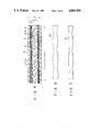
- helical tube 14is disposed inside flexible tube assembly 10 so as to prevent flexible tube assembly 10 from collapsing due to external force.
- Light and image guides and a channel tube(all of which are not shown) are stored in the inner space of helical tube 14.
- Helical tube 14is constituted by helically wound belt-like plate 22 with gaps 16.
- the outer surface of helical tube 14is covered with net tube 18 to prevent flexible tube assembly 10 from twisting.
- the outer surface of net tube 18is covered with outer sheath 20 formed of a thermoplastic elastomer.
- a flexible tube assembly according to a first embodiment of the present inventionwill be described with reference to FIGS. 3 and 4.
- insertion section 8 of the endoscopecomprises flexible tube assembly 10.
- Helical tube 14is arranged at an innermost portion of flexible tube assembly 10.
- Net tube 18covers the outer surface of helical tube 14.
- outer sheath 20formed of a thermoplastic elastomer.
- Helical tube 14is constituted by belt-like plate 22 composed of a metal or plastic wound in a helical shape. That is, helical tube 14 is formed by helically winding belt-like plate 22 having a predetermined width along the axial direction of flexible tube assembly 10. The coil widths of belt-like plate 22 constituting helical tube 14 and each gap 16 between the coils of beltlike plate 22 are respectively set to be l and s.
- flexible tube assembly 10is formed so as to have gap s satisfying the following inequality:
- length L1 of a central line of flexible tube assembly 10is given as:
- number n of plate coils having widths l of helical tube 14 present within length L1can be given as:
- inradius R of the outer surface of helical tube 14 located inside central line 26 of flexible tube assembly 10is given as:
- Length L2 of an arc constituting the semicircle with radius R in the axial directionis given as:
- width lis to be present within length L2 while inequality of s ⁇ 0 is satisfied, the following inequality must be satisfied:
- each gap sis set to be 3 mm or more, a corresponding portion of net tube 18 is inserted in gap s upon the bending of flexible tube assembly 10. Therefore, 3 ⁇ s (mm) must be satisfied.
- width lis preferably set to be 1 to 5 mm so as to obtain a strength for maintaining the shape of helical tube 14 when it is bent at inradius R.
- a second embodiment of the present inventionwill be described with reference to FIG. 5.
- the fundamental structure of the second embodimentis substantially the same as that of the first embodiment. Therefore, the same reference numerals in the second embodiment denote the same parts as in the first embodiment, and a description thereof will be omitted.
- helical tube 14is formed into a three-layer structure having three concentrical layers.
- Helical tube 14is designed such that gaps 16 of the overlapping layers do not overlap each other.
- coil width l in the axial direction of the three layers of helical tube 14 and gap 16 formed between adjacent coils of each layerare respectively set to be identical to one another.
- helical tube 14 described abovehas the three layers, the present invention is not limited to this arrangement.
- the same effect as in the first embodimentcan be obtained by setting the size corresponding to t in the first embodiment to be the thickness of the overall helical tube in the overlapping state.
- a third embodiment of the present inventionwill be described with reference to FIGS. 6 to 8.
- the fundamental structure of the third embodimentis substantially the same as that of the first embodiment. Therefore, the same reference numerals in the third embodiment denote the same parts as in the first embodiment, and a description thereof will be omitted.
- belt-like plate 22 formed to have width l with a constant rate of change in the longitudinal direction as shown in FIGS. 6 and 7is wound such that widths l and gaps s are respectively changed in the axial direction of flexible tube assembly 10.
- widths l of the coils present within arbitrary length L1 of flexible tube assembly 10is given as: ##EQU1##
- the sum of gaps sis represented by: ##EQU2## Since n coils of width l are present within length L1, the mean value of widths l is given as: ##EQU3## Similarly, the mean value of gaps s is given as: ##EQU4##
- a fourth embodimentwill be described with reference to FIG. 9.
- the fundamental structure of the fourth embodimentis substantially the same as that of each of the above-described embodiments. Therefore, the same reference numerals in the fourth embodiment denote the same parts as in each of the embodiments, and a description thereof will be omitted.
- widths l of coils of belt-like plate 22 of helical tube 14are constant, however, gaps 16 are formed so as to have varying widths along the axial direction when belt-like plate 22 is helically wound.
- the flexible tube assembly with the above arrangementis formed in substantially the same manner as in the third embodiment. Since widths l of coils of belt-like plate 22 of helical tube 14 are constant throughout the entire length, the respective values in the fourth embodiment can be represented by the formulas in the third embodiment except for equation (14). That is, the same effect as in each of the above-described embodiments can be obtained by substituting gap s represented by ##EQU5## for s in inequality (1) and setting the size of each portion so as to satisfy inequality (1).
Landscapes
- Health & Medical Sciences (AREA)
- Life Sciences & Earth Sciences (AREA)
- Surgery (AREA)
- Physics & Mathematics (AREA)
- Optics & Photonics (AREA)
- Biomedical Technology (AREA)
- Animal Behavior & Ethology (AREA)
- Radiology & Medical Imaging (AREA)
- Nuclear Medicine, Radiotherapy & Molecular Imaging (AREA)
- Engineering & Computer Science (AREA)
- Biophysics (AREA)
- Heart & Thoracic Surgery (AREA)
- Medical Informatics (AREA)
- Molecular Biology (AREA)
- Pathology (AREA)
- General Health & Medical Sciences (AREA)
- Public Health (AREA)
- Veterinary Medicine (AREA)
- Gastroenterology & Hepatology (AREA)
- Astronomy & Astrophysics (AREA)
- General Physics & Mathematics (AREA)
- Endoscopes (AREA)
- Instruments For Viewing The Inside Of Hollow Bodies (AREA)
Abstract
Description
3≧s≧l(d/2+t)/(30+D/2-d/2-1) (mm)
3≧s≧l(d/2+t)/(30+D/2-d/2-1) (mm)
3≧s≧l(d/2+t)/(30+D/2-d/2-t) unit: mm (1)
L1=2×π×(30+D/2)×1/2 (2)
=π(30+D/2) (3)
n=L1/(l+s) (4)
n=π(30+D/2)/(l+s) (5)
R=30+D/2-d/2-t (6)
L2=2·π·R×1/2 (7)
L2=π(30+D/2-d/2-t) (8)
L2≧ln (9)
Then,
π(30+D/2-d/2-t)≧l ×π(30+D/2)/(l+s) (10)
In addition, s can be given as:
s≧l(d/2+t)/(30+D/2-d/2-t) (11)
3≧s≧l(d/2+1)/(30+D/2-d/2-t) (1)
3≧s≧l(d/2+t)/(30+D/2-d/2-t) (1)
3≧s≧l(d/2+t)/(30+D/2-d/2-t) (1)
Claims (6)
3≧s≧l(d/2+t)/(30+D/2-d/2-t) (mm);
Applications Claiming Priority (2)
| Application Number | Priority Date | Filing Date | Title |
|---|---|---|---|
| JP62-103250 | 1987-04-28 | ||
| JP62103250AJPS63270021A (en) | 1987-04-28 | 1987-04-28 | Flexible tube for endoscope |
Publications (1)
| Publication Number | Publication Date |
|---|---|
| US4805595Atrue US4805595A (en) | 1989-02-21 |
Family
ID=14349197
Family Applications (1)
| Application Number | Title | Priority Date | Filing Date |
|---|---|---|---|
| US07/184,289Expired - LifetimeUS4805595A (en) | 1987-04-28 | 1988-04-21 | Flexible tube assembly for endoscope |
Country Status (2)
| Country | Link |
|---|---|
| US (1) | US4805595A (en) |
| JP (1) | JPS63270021A (en) |
Cited By (34)
| Publication number | Priority date | Publication date | Assignee | Title |
|---|---|---|---|---|
| US5275152A (en)* | 1992-07-27 | 1994-01-04 | Welch Allyn, Inc. | Insertion tube terminator |
| US5279281A (en)* | 1990-09-14 | 1994-01-18 | Harvey James C | Single-handed fibre-optic flexible laryngoscope |
| US5381782A (en)* | 1992-01-09 | 1995-01-17 | Spectrum Medsystems Corporation | Bi-directional and multi-directional miniscopes |
| US5634880A (en)* | 1995-05-22 | 1997-06-03 | Johnson & Johnson Medical, Inc. | Endoscope pressure equalization system and method |
| US5873866A (en)* | 1995-01-13 | 1999-02-23 | Fuji Photo Optical Co., Ltd. | Flexible sheathing tube construction, and method for fabrication thereof |
| US5878483A (en)* | 1995-06-01 | 1999-03-09 | International Business Machines Corporation | Hammer for forming bulges in an array of compliant pin blanks |
| US6083152A (en)* | 1999-01-11 | 2000-07-04 | Welch Allyn, Inc. | Endoscopic insertion tube |
| US6572535B2 (en)* | 2001-03-12 | 2003-06-03 | Olympus Optical Co., Ltd. | Endoscope |
| EP1475031A1 (en)* | 2003-05-05 | 2004-11-10 | STM Medizintechnik Starnberg GmbH | Endoscope shaft |
| US20050165275A1 (en)* | 2004-01-22 | 2005-07-28 | Kenneth Von Felten | Inspection device insertion tube |
| US20070233043A1 (en)* | 2006-03-31 | 2007-10-04 | Boston Scientific Scimed, Inc. | Flexible device shaft with angled spiral wrap |
| WO2008068708A1 (en)* | 2006-12-04 | 2008-06-12 | Koninklijke Philips Electronics N.V. | New bending neck for transesophageal echocardiography (tee) probe |
| US20100023010A1 (en)* | 2005-05-18 | 2010-01-28 | Nelson Charles L | Fracture fixation device, tools and methods |
| US20100145150A1 (en)* | 2008-12-04 | 2010-06-10 | Fujifilm Corporation | Endoscope flexible portion and endoscope |
| US20100145151A1 (en)* | 2008-12-10 | 2010-06-10 | Fujifilm Corporation | Endoscope soft portion and endoscope |
| US20100249511A1 (en)* | 2007-02-26 | 2010-09-30 | Machida Endoscope Co., Ltd. | Flexible endoscope suitable for mri |
| US20110087227A1 (en)* | 2008-12-18 | 2011-04-14 | Mazur Kal U | Bone fixation device, tools and methods |
| US20110144645A1 (en)* | 2006-11-22 | 2011-06-16 | Sonoma Orthopedic Products, Inc. | Fracture Fixation Device, Tools and Methods |
| US20120243840A1 (en)* | 2011-03-23 | 2012-09-27 | Mori Seiki Co., Ltd. | Optical fiber unit |
| US20140142387A1 (en)* | 2012-11-15 | 2014-05-22 | Viktor Josef Wimmer | Unknown |
| US20140261841A1 (en)* | 2013-03-14 | 2014-09-18 | Robert Bosch Gmbh | Kink resistant hose system with coil layer and method of manufacturing |
| US8942530B2 (en) | 2011-09-20 | 2015-01-27 | San Marino Capital, Inc. | Endoscope connector method and apparatus |
| US8961516B2 (en) | 2005-05-18 | 2015-02-24 | Sonoma Orthopedic Products, Inc. | Straight intramedullary fracture fixation devices and methods |
| US9060820B2 (en) | 2005-05-18 | 2015-06-23 | Sonoma Orthopedic Products, Inc. | Segmented intramedullary fracture fixation devices and methods |
| US9155574B2 (en) | 2006-05-17 | 2015-10-13 | Sonoma Orthopedic Products, Inc. | Bone fixation device, tools and methods |
| CN104997481A (en)* | 2015-08-13 | 2015-10-28 | 常州延顺光电科技有限公司 | Main hose device of colonoscope |
| US20160249786A1 (en)* | 2013-12-06 | 2016-09-01 | Olympus Corporation | Passive bending section for endoscope, and endoscope |
| US20170261135A1 (en)* | 2014-12-02 | 2017-09-14 | Olympus Corporation | Flexible tube and insertion apparatus |
| US9770278B2 (en) | 2014-01-17 | 2017-09-26 | Arthrex, Inc. | Dual tip guide wire |
| US9814499B2 (en) | 2014-09-30 | 2017-11-14 | Arthrex, Inc. | Intramedullary fracture fixation devices and methods |
| US9883789B2 (en)* | 2013-12-06 | 2018-02-06 | Olympus Corporation | Flexible tube for endoscope, and endoscope |
| US10765307B2 (en) | 2003-04-01 | 2020-09-08 | Boston Scientific Scimed, Inc. | Endoscopic imaging system |
| US20200367722A1 (en)* | 2013-03-15 | 2020-11-26 | Dvl, Inc. | System and device for visualization of an enclosed space |
| US11350812B2 (en)* | 2018-08-30 | 2022-06-07 | Karl Storz Se & Co. Kg | Endoscope shaft having a layered structure, and method for producing same |
Families Citing this family (2)
| Publication number | Priority date | Publication date | Assignee | Title |
|---|---|---|---|---|
| JP2541872B2 (en)* | 1990-11-20 | 1996-10-09 | 三菱電線工業株式会社 | Medical tubular body |
| MX350734B (en)* | 2010-09-08 | 2017-09-15 | Covidien Lp | Catheter with imaging assembly. |
Citations (8)
| Publication number | Priority date | Publication date | Assignee | Title |
|---|---|---|---|---|
| US779374A (en)* | 1903-08-22 | 1905-01-03 | Ross M G Phillips | Flexible shaft. |
| US3670721A (en)* | 1970-02-05 | 1972-06-20 | Olympus Optical Co | Endoscope |
| US4327711A (en)* | 1979-11-16 | 1982-05-04 | Olympus Optical Co., Ltd. | Flexible tube for an endoscope |
| US4329980A (en)* | 1979-03-06 | 1982-05-18 | Olympus Optical Co., Ltd. | Flexible sheath for an endoscope |
| JPS59190201A (en)* | 1983-04-13 | 1984-10-29 | コノコ・インコ−ポレ−テツド | Manufacture of hydrogen and carbon monoxide by dissociation of methanol |
| JPS60187701A (en)* | 1984-03-06 | 1985-09-25 | Toshiba Corp | Gas turbine cooling blade |
| US4669172A (en)* | 1983-02-07 | 1987-06-02 | Circon Corporation | Method for fabrication of flexible shaft |
| US4753222A (en)* | 1985-12-13 | 1988-06-28 | Olympus Optical Co., Ltd. | Endoscopic flexible tube |
Family Cites Families (1)
| Publication number | Priority date | Publication date | Assignee | Title |
|---|---|---|---|---|
| JPS58103431A (en)* | 1981-12-12 | 1983-06-20 | オリンパス光学工業株式会社 | Flexible tube of endoscope |
- 1987
- 1987-04-28JPJP62103250Apatent/JPS63270021A/enactivePending
- 1988
- 1988-04-21USUS07/184,289patent/US4805595A/ennot_activeExpired - Lifetime
Patent Citations (8)
| Publication number | Priority date | Publication date | Assignee | Title |
|---|---|---|---|---|
| US779374A (en)* | 1903-08-22 | 1905-01-03 | Ross M G Phillips | Flexible shaft. |
| US3670721A (en)* | 1970-02-05 | 1972-06-20 | Olympus Optical Co | Endoscope |
| US4329980A (en)* | 1979-03-06 | 1982-05-18 | Olympus Optical Co., Ltd. | Flexible sheath for an endoscope |
| US4327711A (en)* | 1979-11-16 | 1982-05-04 | Olympus Optical Co., Ltd. | Flexible tube for an endoscope |
| US4669172A (en)* | 1983-02-07 | 1987-06-02 | Circon Corporation | Method for fabrication of flexible shaft |
| JPS59190201A (en)* | 1983-04-13 | 1984-10-29 | コノコ・インコ−ポレ−テツド | Manufacture of hydrogen and carbon monoxide by dissociation of methanol |
| JPS60187701A (en)* | 1984-03-06 | 1985-09-25 | Toshiba Corp | Gas turbine cooling blade |
| US4753222A (en)* | 1985-12-13 | 1988-06-28 | Olympus Optical Co., Ltd. | Endoscopic flexible tube |
Cited By (58)
| Publication number | Priority date | Publication date | Assignee | Title |
|---|---|---|---|---|
| US5279281A (en)* | 1990-09-14 | 1994-01-18 | Harvey James C | Single-handed fibre-optic flexible laryngoscope |
| US5381782A (en)* | 1992-01-09 | 1995-01-17 | Spectrum Medsystems Corporation | Bi-directional and multi-directional miniscopes |
| US5275152A (en)* | 1992-07-27 | 1994-01-04 | Welch Allyn, Inc. | Insertion tube terminator |
| US5873866A (en)* | 1995-01-13 | 1999-02-23 | Fuji Photo Optical Co., Ltd. | Flexible sheathing tube construction, and method for fabrication thereof |
| US5634880A (en)* | 1995-05-22 | 1997-06-03 | Johnson & Johnson Medical, Inc. | Endoscope pressure equalization system and method |
| US5807238A (en)* | 1995-05-22 | 1998-09-15 | Johnson & Johnson Medical, Inc. | Endoscope pressure equalization system and method |
| US5878483A (en)* | 1995-06-01 | 1999-03-09 | International Business Machines Corporation | Hammer for forming bulges in an array of compliant pin blanks |
| US6083152A (en)* | 1999-01-11 | 2000-07-04 | Welch Allyn, Inc. | Endoscopic insertion tube |
| US6572535B2 (en)* | 2001-03-12 | 2003-06-03 | Olympus Optical Co., Ltd. | Endoscope |
| US10765307B2 (en) | 2003-04-01 | 2020-09-08 | Boston Scientific Scimed, Inc. | Endoscopic imaging system |
| US11324395B2 (en) | 2003-04-01 | 2022-05-10 | Boston Scientific Scimed, Inc. | Endoscopic imaging system |
| US20050004434A1 (en)* | 2003-05-05 | 2005-01-06 | Konstantin Bob | Endoscope shaft |
| EP1475031A1 (en)* | 2003-05-05 | 2004-11-10 | STM Medizintechnik Starnberg GmbH | Endoscope shaft |
| US7311659B2 (en) | 2003-05-05 | 2007-12-25 | Stm Medizintechnik Stamberg Gmbh | Endoscope shaft |
| US20050165275A1 (en)* | 2004-01-22 | 2005-07-28 | Kenneth Von Felten | Inspection device insertion tube |
| US8287541B2 (en)* | 2005-05-18 | 2012-10-16 | Sonoma Orthopedic Products, Inc. | Fracture fixation device, tools and methods |
| US9060820B2 (en) | 2005-05-18 | 2015-06-23 | Sonoma Orthopedic Products, Inc. | Segmented intramedullary fracture fixation devices and methods |
| US8961516B2 (en) | 2005-05-18 | 2015-02-24 | Sonoma Orthopedic Products, Inc. | Straight intramedullary fracture fixation devices and methods |
| US8287539B2 (en) | 2005-05-18 | 2012-10-16 | Sonoma Orthopedic Products, Inc. | Fracture fixation device, tools and methods |
| US20100023010A1 (en)* | 2005-05-18 | 2010-01-28 | Nelson Charles L | Fracture fixation device, tools and methods |
| US20100094347A1 (en)* | 2005-05-18 | 2010-04-15 | Nelson Charles L | Fracture fixation device, tools and methods |
| WO2007114867A1 (en)* | 2006-03-31 | 2007-10-11 | Boston Scientific Limited | Flexible device shaft with angled spiral wrap |
| US7579550B2 (en) | 2006-03-31 | 2009-08-25 | Boston Scientific Scimed, Inc. | Flexible device shaft with angled spiral wrap |
| US8677602B2 (en) | 2006-03-31 | 2014-03-25 | Boston Scientific Scimed, Inc. | Method of making a flexible device shaft with angled spiral wrap |
| US20070233043A1 (en)* | 2006-03-31 | 2007-10-04 | Boston Scientific Scimed, Inc. | Flexible device shaft with angled spiral wrap |
| US20090312606A1 (en)* | 2006-03-31 | 2009-12-17 | Boston Scientific Scimed, Inc. | Flexible device shaft with angled spiral wrap |
| US8124876B2 (en) | 2006-03-31 | 2012-02-28 | Boston Scientific Scimed, Inc. | Flexible device shaft with angled spiral wrap |
| US9155574B2 (en) | 2006-05-17 | 2015-10-13 | Sonoma Orthopedic Products, Inc. | Bone fixation device, tools and methods |
| US20110144645A1 (en)* | 2006-11-22 | 2011-06-16 | Sonoma Orthopedic Products, Inc. | Fracture Fixation Device, Tools and Methods |
| US8439917B2 (en) | 2006-11-22 | 2013-05-14 | Sonoma Orthopedic Products, Inc. | Fracture fixation device, tools and methods |
| US9259250B2 (en) | 2006-11-22 | 2016-02-16 | Sonoma Orthopedic Products, Inc. | Fracture fixation device, tools and methods |
| WO2008068708A1 (en)* | 2006-12-04 | 2008-06-12 | Koninklijke Philips Electronics N.V. | New bending neck for transesophageal echocardiography (tee) probe |
| US20100016660A1 (en)* | 2006-12-04 | 2010-01-21 | Koninklijke Philips Electronics N.V. | Bending neck for transesophageal echocardiography (tee) probe |
| US20100249511A1 (en)* | 2007-02-26 | 2010-09-30 | Machida Endoscope Co., Ltd. | Flexible endoscope suitable for mri |
| US8696551B2 (en)* | 2007-02-26 | 2014-04-15 | Machida Endoscope Co., Ltd. | Flexible endoscope suitable for MRI |
| US20100145150A1 (en)* | 2008-12-04 | 2010-06-10 | Fujifilm Corporation | Endoscope flexible portion and endoscope |
| US20100145151A1 (en)* | 2008-12-10 | 2010-06-10 | Fujifilm Corporation | Endoscope soft portion and endoscope |
| US8568413B2 (en) | 2008-12-18 | 2013-10-29 | Sonoma Orthopedic Products, Inc. | Bone fixation device, tools and methods |
| US20110087227A1 (en)* | 2008-12-18 | 2011-04-14 | Mazur Kal U | Bone fixation device, tools and methods |
| US9020314B2 (en)* | 2011-03-23 | 2015-04-28 | Mori Seiki Co., Ltd. | Optical fiber unit |
| US20120243840A1 (en)* | 2011-03-23 | 2012-09-27 | Mori Seiki Co., Ltd. | Optical fiber unit |
| US8942530B2 (en) | 2011-09-20 | 2015-01-27 | San Marino Capital, Inc. | Endoscope connector method and apparatus |
| US9549662B2 (en) | 2011-09-20 | 2017-01-24 | San Marino Capital, Inc. | Endoscope connector method and apparatus |
| US9351630B2 (en)* | 2012-11-15 | 2016-05-31 | Karl Storz Gmbh & Co. Kg | Flexible endoscope shaft, and endoscope with same |
| US20140142387A1 (en)* | 2012-11-15 | 2014-05-22 | Viktor Josef Wimmer | Unknown |
| US20140261841A1 (en)* | 2013-03-14 | 2014-09-18 | Robert Bosch Gmbh | Kink resistant hose system with coil layer and method of manufacturing |
| US20200367722A1 (en)* | 2013-03-15 | 2020-11-26 | Dvl, Inc. | System and device for visualization of an enclosed space |
| US12108938B2 (en)* | 2013-03-15 | 2024-10-08 | Dvl, Inc. | System and device for visualization of an enclosed space |
| US20160249786A1 (en)* | 2013-12-06 | 2016-09-01 | Olympus Corporation | Passive bending section for endoscope, and endoscope |
| US9814373B2 (en)* | 2013-12-06 | 2017-11-14 | Olympus Corporation | Passive bending section for endoscope, and endoscope |
| US9883789B2 (en)* | 2013-12-06 | 2018-02-06 | Olympus Corporation | Flexible tube for endoscope, and endoscope |
| US9770278B2 (en) | 2014-01-17 | 2017-09-26 | Arthrex, Inc. | Dual tip guide wire |
| US10548648B2 (en) | 2014-09-30 | 2020-02-04 | Arthrex, Inc. | Intramedullary fracture fixation devices and methods |
| US9814499B2 (en) | 2014-09-30 | 2017-11-14 | Arthrex, Inc. | Intramedullary fracture fixation devices and methods |
| US10234062B2 (en)* | 2014-12-02 | 2019-03-19 | Olympus Corporation | Flexible tube and insertion apparatus |
| US20170261135A1 (en)* | 2014-12-02 | 2017-09-14 | Olympus Corporation | Flexible tube and insertion apparatus |
| CN104997481A (en)* | 2015-08-13 | 2015-10-28 | 常州延顺光电科技有限公司 | Main hose device of colonoscope |
| US11350812B2 (en)* | 2018-08-30 | 2022-06-07 | Karl Storz Se & Co. Kg | Endoscope shaft having a layered structure, and method for producing same |
Also Published As
| Publication number | Publication date |
|---|---|
| JPS63270021A (en) | 1988-11-08 |
Similar Documents
| Publication | Publication Date | Title |
|---|---|---|
| US4805595A (en) | Flexible tube assembly for endoscope | |
| US5449021A (en) | Bending device | |
| CA1258840A (en) | Fiberscope with bending mechanism | |
| US4770188A (en) | Guide tube assembly for an endoscope | |
| EP0448284B1 (en) | Bending device | |
| JP3067255B2 (en) | Angle for bending operation device | |
| US4236509A (en) | Curving device in an endoscope | |
| EP0183585A2 (en) | Flexible plastic tube for endoscopes and the like | |
| EP0422842A2 (en) | Bending device | |
| NO962302L (en) | Variable stiffness spirals | |
| EP3284389A1 (en) | Flexible tube, and insertable device and endoscope using same | |
| EP0547509B1 (en) | A tip articulation mechanism for endoscopes | |
| JP2875583B2 (en) | Bending section for bending operation device | |
| JPS58103431A (en) | Flexible tube of endoscope | |
| JPS6041205Y2 (en) | Endoscope | |
| JPH0546723Y2 (en) | ||
| JPH0717283Y2 (en) | Flexible tube for endoscope | |
| JP2554817Y2 (en) | Flexible tube of endoscope | |
| JPS6160688B2 (en) | ||
| JPH0434496Y2 (en) | ||
| JPS6324886Y2 (en) | ||
| JPS6330404Y2 (en) | ||
| JPS637206Y2 (en) | ||
| JP2537612Y2 (en) | Flexible tube of endoscope | |
| JPH0342895B2 (en) |
Legal Events
| Date | Code | Title | Description |
|---|---|---|---|
| AS | Assignment | Owner name:OLYMPUS OPTICAL CO., LTD., 43-2, 2-CHOME, HATAGAYA Free format text:ASSIGNMENT OF ASSIGNORS INTEREST.;ASSIGNOR:KANBARA, KOJI;REEL/FRAME:004879/0845 Effective date:19880411 Owner name:OLYMPUS OPTICAL CO., LTD., A CORP. OF JAPAN,JAPAN Free format text:ASSIGNMENT OF ASSIGNORS INTEREST;ASSIGNOR:KANBARA, KOJI;REEL/FRAME:004879/0845 Effective date:19880411 | |
| STCF | Information on status: patent grant | Free format text:PATENTED CASE | |
| FEPP | Fee payment procedure | Free format text:PAYOR NUMBER ASSIGNED (ORIGINAL EVENT CODE: ASPN); ENTITY STATUS OF PATENT OWNER: LARGE ENTITY | |
| FPAY | Fee payment | Year of fee payment:4 | |
| FEPP | Fee payment procedure | Free format text:PAYER NUMBER DE-ASSIGNED (ORIGINAL EVENT CODE: RMPN); ENTITY STATUS OF PATENT OWNER: LARGE ENTITY Free format text:PAYOR NUMBER ASSIGNED (ORIGINAL EVENT CODE: ASPN); ENTITY STATUS OF PATENT OWNER: LARGE ENTITY | |
| FPAY | Fee payment | Year of fee payment:8 | |
| FPAY | Fee payment | Year of fee payment:12 |