US4805504A - Safety cover for miter saw - Google Patents
Safety cover for miter sawDownload PDFInfo
- Publication number
- US4805504A US4805504AUS07/137,668US13766887AUS4805504AUS 4805504 AUS4805504 AUS 4805504AUS 13766887 AUS13766887 AUS 13766887AUS 4805504 AUS4805504 AUS 4805504A
- Authority
- US
- United States
- Prior art keywords
- safety cover
- saw
- blade
- mounting arm
- saw unit
- Prior art date
- Legal status (The legal status is an assumption and is not a legal conclusion. Google has not performed a legal analysis and makes no representation as to the accuracy of the status listed.)
- Expired - Lifetime
Links
- 238000005520cutting processMethods0.000description4
- 238000000034methodMethods0.000description1
- 238000012986modificationMethods0.000description1
- 230000004048modificationEffects0.000description1
Images


Classifications
- B—PERFORMING OPERATIONS; TRANSPORTING
- B27—WORKING OR PRESERVING WOOD OR SIMILAR MATERIAL; NAILING OR STAPLING MACHINES IN GENERAL
- B27G—ACCESSORY MACHINES OR APPARATUS FOR WORKING WOOD OR SIMILAR MATERIALS; TOOLS FOR WORKING WOOD OR SIMILAR MATERIALS; SAFETY DEVICES FOR WOOD WORKING MACHINES OR TOOLS
- B27G19/00—Safety guards or devices specially adapted for wood saws; Auxiliary devices facilitating proper operation of wood saws
- B27G19/02—Safety guards or devices specially adapted for wood saws; Auxiliary devices facilitating proper operation of wood saws for circular saws
- Y—GENERAL TAGGING OF NEW TECHNOLOGICAL DEVELOPMENTS; GENERAL TAGGING OF CROSS-SECTIONAL TECHNOLOGIES SPANNING OVER SEVERAL SECTIONS OF THE IPC; TECHNICAL SUBJECTS COVERED BY FORMER USPC CROSS-REFERENCE ART COLLECTIONS [XRACs] AND DIGESTS
- Y10—TECHNICAL SUBJECTS COVERED BY FORMER USPC
- Y10T—TECHNICAL SUBJECTS COVERED BY FORMER US CLASSIFICATION
- Y10T83/00—Cutting
- Y10T83/606—Interrelated tool actuating means and guard means
- Y—GENERAL TAGGING OF NEW TECHNOLOGICAL DEVELOPMENTS; GENERAL TAGGING OF CROSS-SECTIONAL TECHNOLOGIES SPANNING OVER SEVERAL SECTIONS OF THE IPC; TECHNICAL SUBJECTS COVERED BY FORMER USPC CROSS-REFERENCE ART COLLECTIONS [XRACs] AND DIGESTS
- Y10—TECHNICAL SUBJECTS COVERED BY FORMER USPC
- Y10T—TECHNICAL SUBJECTS COVERED BY FORMER US CLASSIFICATION
- Y10T83/00—Cutting
- Y10T83/768—Rotatable disc tool pair or tool and carrier
- Y10T83/7734—With guard for tool
- Y—GENERAL TAGGING OF NEW TECHNOLOGICAL DEVELOPMENTS; GENERAL TAGGING OF CROSS-SECTIONAL TECHNOLOGIES SPANNING OVER SEVERAL SECTIONS OF THE IPC; TECHNICAL SUBJECTS COVERED BY FORMER USPC CROSS-REFERENCE ART COLLECTIONS [XRACs] AND DIGESTS
- Y10—TECHNICAL SUBJECTS COVERED BY FORMER USPC
- Y10T—TECHNICAL SUBJECTS COVERED BY FORMER US CLASSIFICATION
- Y10T83/00—Cutting
- Y10T83/768—Rotatable disc tool pair or tool and carrier
- Y10T83/7755—Carrier for rotatable tool movable during cutting
- Y10T83/7788—Tool carrier oscillated or rotated
Definitions
- the present inventionrelates to power miter saws, and more particularly to a safety cover for such miter saws which may cover the saw blade as fully as possible even during operation.
- Such miter sawsmay include a miter saw unit pivotally connected to a support base for pivotal movement between a raised rest position and a lowered operational position.
- the saw unitincludes an electric motor which rotatably drives a circular saw blade; and a blade case which partially encases the saw blade.
- a safety coveris pivotally mounted on the blade case for covering the saw blade. The safety cover is mounted in a manner such that it will be swung clear of the saw blade upon its engagement with a workpiece when the saw unit is lowered to its operational position.
- Typical prior art devices of this general typeare disclosed by U.S. Pat. Nos. 3,821,918 and 3,994,192.
- the safety coveris swung upon its engagement with the workpiece when the saw is pivoted from its rest position to its operational position.
- the safety coveris pivoted indirectly through the workpiece, so that the movement of the safety cover is inconstant depending on the condition of the workpiece, thus lacking in smoothness and reliability.
- a cut-off portion or chip of the workpiecebeing unfixed or free on the support base, can often engage the safety cover, causing the latter to turn upwardly to expose a portion of the saw blade.
- the safety coveris simply spring biased for pivotal movement relative to the blade case, it can be manually pivoted by the operator even in a normal operating condition. This is disadvantageous from the standpoint of safety.
- the power miter sawincludes, according to the present invention, a support base and a mounting arm connected to the support base for swinging movement around a vertical axis.
- a miter saw unitis pivotally connected to the mounting arm.
- the miter saw unitincludes a circular saw blade and a drive motor for driving the saw blade.
- a blade caseis attached to the miter saw unit and is adapted to partially encase the saw blade so as to provide an exposed operational portion of the saw blade.
- a movable safety coveris mounted on the blade case so as to cover the exposed operational portion of the saw blade.
- Actuating meansis disposed between the mounting arm and the safety cover for directly associating the safety cover with the pivotal movement of the miter saw unit.
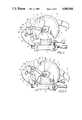
- FIG. 1is a side view of a power miter saw embodying the present invention
- FIG. 2is a plan view of the miter saw shown in FIG. 1;
- FIG. 3is an enlarged sectional view taken in the direction of the arrows substantially on line III--III of FIG. 1;
- FIGS. 4 and 5are side views illustrating various phases of operation through the miter saw.
- FIG. 6is a schematic view illustrating various operational positions of the actuating link and the safety cover.
- the miter sawincludes a support base 1 and a miter saw unit 2.
- the support base 1includes a rotatably mounted turntable 3 and a clamp 4 for clamping a workpiece W.
- a mounting arm 5is fixedly connected to the rear end of the turntable 3 for swinging movement around a vertical axis.
- the miter saw unit 2is mainly comprised of a drive motor 6 having a shaft 6a and a housing 6b; a circular saw blade 7 mounted on the motor shaft 6a and a blade case 8 attached to the motor housing 6b and adapted to cover substantially half the saw blade 7.
- the motor housing 6bhas integrally formed a control handle 9 which projects from one side thereof and a support arm 10 which projects from the other side thereof in opposed relation to the handle 9.
- the support arm 10is pivotally supported generally on the upper end of the mounting arm 5 through a support shaft 11 (FIG. 1) and therefore, the miter saw unit 2 is pivotally mounted on the support base 1, between a raised rest position and a lowered operational position.
- the miter saw unit 2may be manually moved toward the support base 1 through the handle 9, and it may be positively returned under the biasing force of a return spring (not shown) resiliently mounted on the support shaft 11 between the support arm 10 and the mounting arm 5.
- the extent of the swinging return movement of the miter saw unit 2is restricted by a stopper (not shown) substantially to the position shown in FIG. 1.
- the blade case 8has a cutout portion 8a formed generally in opposed relation to the central mounting portion of the saw blade 7 (FIG. 3).
- a mounting cap 12is provided generally in opposed relation to the cutout portion 8a and is adapted to mount a safety cover which will be described later.
- the mounting cap 12has a large diameter boss portion 12a in alignment with the central mounting portion of the saw blade 7 and a substantially elliptical flange portion 12b extending outwardly from the boss portion 12a (FIG. 1).
- the flange portion 12bis pivotally supported at one end to the blade case 8 through a support pin 13.
- the other end of the flange portion 12bforms a hooked engaging portion 14 which is releasably fastened to the blade case 8 by a locking bolt 15.
- a substantially sectorial safety cover 16is provided and is adapted to cover a portion of the saw blade 7 exposed from the blade case 8.
- the safety cover 16has a central mounting hole 16a in which the boss portion 12b of the mounting cap 12 is received, so that the safety cover 16 is mounted on the mounting cap 12 in a pivotable manner.
- the safety cover 16also has adjacent the central mounting hole 16a a flange portion 16b from which a first engaging pin 17 is projected at a location intermediate between the support pin 13 of the mounting cap 12 and the locking bolt 15 of the engaging portion 14.
- a spiral spring 18is resiliently positioned between the flange portion 12b of the mounting cap 12 and the flange portion 16b of the safety cover 16 and is adapted to impart biasing force to the safety cover 16 to cause swinging return movement thereof.
- a retaining disc plate 19is fastened by a screw to the boss portion 12a of the mounting cap 12 so as to prevent the safety cover 16 from falling out of the boss portion 12a of the mounting cap 12.
- An actuating link 20 of crooked configurationis pivotally connected at the bent portion thereof to one side of the blade case 8 through a support pin 21.
- the actuating link 20has one end located in opposed relation to the safety cover 16 and the other end located in opposed relation to the mounting arm 5.
- the one end in opposed relation to the safety cover 16is forked to define a first cam groove 22 of crooked configuration, and the first engaging pin 17 is movably fitted in the first cam groove 22.
- the other end in opposed relation to the mounting arm 5also is forked to define a second cam groove 23 of substantially U-shaped configuration and has, across the cam groove 23, one leg forming a stopper piece 24 and the other leg forming a cam piece 25 of substantially L-shaped configuration.
- a mounting plate 26is secured to one side of the mounting arm 5 and has a second engaging pin 27 projecting from the upper end thereof and engageable with the second cam groove 23. When moved out of the second cam groove 23, the second engaging pin 27 may be brought in abutting engagement with a cam face 25a of the cam piece 25.
- the first engaging pin 17is located in the first cam groove 22 at the one end adjacent the entrance thereof, and the second engaging pin 27 is located in the second cam groove 23 at the other end.
- Engagement of the second engaging pin 27 with the stopper piece 24restricts the biasing force of the spiral spring 18 for pivotally returning the safety cover 16, so that the portion of the saw blade 7 exposed from the blade case 8 may be kept covered by the safety cover 16.
- the safety cover 16will not expose the saw blade 7, so long as the second engaging pin 27 is in engagement with the stopper piece 24.
- the drive motor 6is driven to rotate the blade saw 7.
- the saw unit 2As the operator moves the miter saw unit 2 toward the support base 1 by pushing downwardly on the handle 9, the saw unit 2 is pivoted around the support shaft 11 along a vertical path relative to the support base 1.
- This swinging movement of the saw unit 2causes a downward movement of the support pin 21 of the actuating link 20 around the support shaft 11.
- the movement of the other end of the actuating link 20is restricted as the second engaging pin 27 engages the second cam groove 23 and abuts on the cam face 25a of the cam piece 25.
- the actuating link 20is pivoted clockwise around the support pin 21, independently of the swinging movement of the saw unit 2.
- This clockwise movement of the actuating link 20causes the first engaging pin 17 to be moved from the position adjacent the entrance of the first cam groove 22 to an inner position along the crooked configuration.
- the safety cover 16is then positively pivoted counterclockwise around the boss portion 12a of the mounting cap 12 against the biasing force of the spring 18, so that a portion of the circular saw blade 7 may be exposed to the workpiece W (FIGS. 4 and 6).
- the above conditionis maintained during further swinging movement of the saw unit 2 to perform a cutting operation.
- the safety cover 16does not engage the workpiece W (for example, when the size of the workpiece is small as shown by a phantom line in FIG. 5)
- the abutting engagement between the cam face 25a of the cam piece 25 and the second engaging pin 27is maintained, so that the swinging movement of the saw unit 2 causes clockwise movement of the actuating link 20 around the support pin 21 and hence, positive pivotal movement of the safety cover 16 in the counterclockwise direction.
- the safety cover 16is then lowered until it engages the turntable 3, and this condition is maintained, as with the above condition in which the safety cover 16 engages the workpiece W (FIGS. 5 and 6).
- the saw unit 2is pivotally returned to its original position.
- the safety cover 16is gradually pivoted to its original position under the biasing force of the spring 18 so as to cover the exposed portion of the saw blade 7, and the actuating link 20 is returned to its original position by reversing the process described above.
- the locking bolt 15when it is desired to change the saw blade 7, the locking bolt 15 is released to turn the mounting cap 12 along with the safety cover 16 around the support pin 13, as shown by a phantom line in FIG. 1, so that the opening of the blade case 8 may be widely exposed to facilitate changing of the saw blade 7.
- the safety cover 16may be positively rotated by the actuating link 20 as the miter saw unit 2 is lowered toward the support base 1 and hence, a miter cutting operation may be performed both easily and safely. Also, it can be seen that while the saw unit 2 is in its raised rest position, the safety cover 16 may be effectively prevented from rotation as it is associated with the actuating link 20 which is locked when the saw unit 2 is in its rest position.
Landscapes
- Life Sciences & Earth Sciences (AREA)
- Engineering & Computer Science (AREA)
- Mechanical Engineering (AREA)
- Wood Science & Technology (AREA)
- Forests & Forestry (AREA)
- Sawing (AREA)
Abstract
Description
1. Field of the Invention
The present invention relates to power miter saws, and more particularly to a safety cover for such miter saws which may cover the saw blade as fully as possible even during operation.
2. Description of the Prior Art
Such miter saws may include a miter saw unit pivotally connected to a support base for pivotal movement between a raised rest position and a lowered operational position. The saw unit includes an electric motor which rotatably drives a circular saw blade; and a blade case which partially encases the saw blade. For safety reasons, a safety cover is pivotally mounted on the blade case for covering the saw blade. The safety cover is mounted in a manner such that it will be swung clear of the saw blade upon its engagement with a workpiece when the saw unit is lowered to its operational position. Typical prior art devices of this general type are disclosed by U.S. Pat. Nos. 3,821,918 and 3,994,192.
In such prior art saws, however, the safety cover is swung upon its engagement with the workpiece when the saw is pivoted from its rest position to its operational position. In other words, the safety cover is pivoted indirectly through the workpiece, so that the movement of the safety cover is inconstant depending on the condition of the workpiece, thus lacking in smoothness and reliability. Especially, during angular cutting operation, a cut-off portion or chip of the workpiece, being unfixed or free on the support base, can often engage the safety cover, causing the latter to turn upwardly to expose a portion of the saw blade. Furthermore, as the safety cover is simply spring biased for pivotal movement relative to the blade case, it can be manually pivoted by the operator even in a normal operating condition. This is disadvantageous from the standpoint of safety.
It is, accordingly, an object of the present invention to eliminate the noted disadvantages of the prior art miter saws.
It is another object of the present invention to provide a safety cover for a power miter saw which is initially pivoted directly by pivotal movement of the miter saw unit, irrespective of presence of a workpiece, so that the safety cover is moved both smoothly and reliably.
It is a further object of the present invention to provide a safety cover for a power miter saw which assures fully covered condition of the saw blade at all times when the miter saw is not in use.
The power miter saw includes, according to the present invention, a support base and a mounting arm connected to the support base for swinging movement around a vertical axis. A miter saw unit is pivotally connected to the mounting arm. The miter saw unit includes a circular saw blade and a drive motor for driving the saw blade. A blade case is attached to the miter saw unit and is adapted to partially encase the saw blade so as to provide an exposed operational portion of the saw blade. A movable safety cover is mounted on the blade case so as to cover the exposed operational portion of the saw blade. Actuating means is disposed between the mounting arm and the safety cover for directly associating the safety cover with the pivotal movement of the miter saw unit.
The present invention will become more fully apparent from the claims and description as it proceeds in connection with the drawings.
FIG. 1 is a side view of a power miter saw embodying the present invention;
FIG. 2 is a plan view of the miter saw shown in FIG. 1;
FIG. 3 is an enlarged sectional view taken in the direction of the arrows substantially on line III--III of FIG. 1;
FIGS. 4 and 5 are side views illustrating various phases of operation through the miter saw; and
FIG. 6 is a schematic view illustrating various operational positions of the actuating link and the safety cover.
Referring to the drawings and to FIG. 1 in particular, shown therein is a power miter saw constructed in accordance with the present invention. As shown therein, the miter saw includes a support base 1 and amiter saw unit 2. The support base 1 includes a rotatably mountedturntable 3 and aclamp 4 for clamping a workpiece W. Amounting arm 5 is fixedly connected to the rear end of theturntable 3 for swinging movement around a vertical axis.
As may be seen in FIGS. 2 and 3, themiter saw unit 2 is mainly comprised of adrive motor 6 having ashaft 6a and ahousing 6b; acircular saw blade 7 mounted on themotor shaft 6a and ablade case 8 attached to themotor housing 6b and adapted to cover substantially half thesaw blade 7. Themotor housing 6b has integrally formed acontrol handle 9 which projects from one side thereof and asupport arm 10 which projects from the other side thereof in opposed relation to thehandle 9. Thesupport arm 10 is pivotally supported generally on the upper end of themounting arm 5 through a support shaft 11 (FIG. 1) and therefore, themiter saw unit 2 is pivotally mounted on the support base 1, between a raised rest position and a lowered operational position. Themiter saw unit 2 may be manually moved toward the support base 1 through thehandle 9, and it may be positively returned under the biasing force of a return spring (not shown) resiliently mounted on thesupport shaft 11 between thesupport arm 10 and themounting arm 5. The extent of the swinging return movement of themiter saw unit 2 is restricted by a stopper (not shown) substantially to the position shown in FIG. 1.
Theblade case 8 has acutout portion 8a formed generally in opposed relation to the central mounting portion of the saw blade 7 (FIG. 3). Amounting cap 12 is provided generally in opposed relation to thecutout portion 8a and is adapted to mount a safety cover which will be described later. Specifically, themounting cap 12 has a largediameter boss portion 12a in alignment with the central mounting portion of thesaw blade 7 and a substantiallyelliptical flange portion 12b extending outwardly from theboss portion 12a (FIG. 1). Theflange portion 12b is pivotally supported at one end to theblade case 8 through asupport pin 13. The other end of theflange portion 12b forms a hookedengaging portion 14 which is releasably fastened to theblade case 8 by alocking bolt 15.
A substantiallysectorial safety cover 16 is provided and is adapted to cover a portion of thesaw blade 7 exposed from theblade case 8. Specifically, as shown in FIG. 3, thesafety cover 16 has acentral mounting hole 16a in which theboss portion 12b of themounting cap 12 is received, so that thesafety cover 16 is mounted on themounting cap 12 in a pivotable manner. Thesafety cover 16 also has adjacent thecentral mounting hole 16a a flange portion 16b from which a firstengaging pin 17 is projected at a location intermediate between thesupport pin 13 of themounting cap 12 and thelocking bolt 15 of theengaging portion 14. Aspiral spring 18 is resiliently positioned between theflange portion 12b of themounting cap 12 and the flange portion 16b of thesafety cover 16 and is adapted to impart biasing force to thesafety cover 16 to cause swinging return movement thereof. Aretaining disc plate 19 is fastened by a screw to theboss portion 12a of themounting cap 12 so as to prevent thesafety cover 16 from falling out of theboss portion 12a of themounting cap 12.
An actuatinglink 20 of crooked configuration is pivotally connected at the bent portion thereof to one side of theblade case 8 through asupport pin 21. Specifically, as shown in FIG. 1, the actuatinglink 20 has one end located in opposed relation to thesafety cover 16 and the other end located in opposed relation to themounting arm 5. The one end in opposed relation to thesafety cover 16 is forked to define afirst cam groove 22 of crooked configuration, and the firstengaging pin 17 is movably fitted in thefirst cam groove 22. The other end in opposed relation to themounting arm 5 also is forked to define asecond cam groove 23 of substantially U-shaped configuration and has, across thecam groove 23, one leg forming astopper piece 24 and the other leg forming acam piece 25 of substantially L-shaped configuration. Amounting plate 26 is secured to one side of themounting arm 5 and has a secondengaging pin 27 projecting from the upper end thereof and engageable with thesecond cam groove 23. When moved out of thesecond cam groove 23, the secondengaging pin 27 may be brought in abutting engagement with acam face 25a of thecam piece 25.
When the actuatinglink 20 thus constructed is in the position shown in FIG. 1 prior to swinging movement of themiter saw unit 2, the firstengaging pin 17 is located in thefirst cam groove 22 at the one end adjacent the entrance thereof, and the secondengaging pin 27 is located in thesecond cam groove 23 at the other end. Engagement of the second engagingpin 27 with thestopper piece 24 restricts the biasing force of thespiral spring 18 for pivotally returning thesafety cover 16, so that the portion of thesaw blade 7 exposed from theblade case 8 may be kept covered by thesafety cover 16. Thus, should a counterclockwise force be applied to thesafety cover 16, for example, by the operator, thesafety cover 16 will not expose thesaw blade 7, so long as the secondengaging pin 27 is in engagement with thestopper piece 24.
The operation of the miter saw thus constructed will now be described with reference to FIGS. 4, 5 and 6.
Assuming that a workpiece W is properly clamped by theclamp 4 on the support base 1, thedrive motor 6 is driven to rotate theblade saw 7. As the operator moves themiter saw unit 2 toward the support base 1 by pushing downwardly on thehandle 9, thesaw unit 2 is pivoted around thesupport shaft 11 along a vertical path relative to the support base 1. This swinging movement of thesaw unit 2 causes a downward movement of thesupport pin 21 of theactuating link 20 around thesupport shaft 11. At this time, however, the movement of the other end of theactuating link 20 is restricted as the secondengaging pin 27 engages thesecond cam groove 23 and abuts on thecam face 25a of thecam piece 25. Thus, theactuating link 20 is pivoted clockwise around thesupport pin 21, independently of the swinging movement of thesaw unit 2. This clockwise movement of theactuating link 20 causes the firstengaging pin 17 to be moved from the position adjacent the entrance of thefirst cam groove 22 to an inner position along the crooked configuration. Thesafety cover 16 is then positively pivoted counterclockwise around theboss portion 12a of the mountingcap 12 against the biasing force of thespring 18, so that a portion of thecircular saw blade 7 may be exposed to the workpiece W (FIGS. 4 and 6).
This condition is maintained, as long as the secondengaging pin 27 is in abutting engagement with thecam face 25a of thecam piece 25, and, as described above, thesafety cover 16 is positively pivoted counterclockwise so as to increase the exposed portion of the circular saw blade 7 (FIG. 6).
When thesaw unit 2 is further moved downwardly, a portion of thesafety cover 16 pivoted as described above engages a portion (upper corner) of the workpiece W, and as thesaw unit 2 is furthermore moved, thesafety cover 16 is independently pivoted counterclockwise around theboss portion 12b of the mountingcap 12, irrespective of rotation of theactuating link 20, because of the engagement of thesafety cover 16 with the workpiece W. In this condition, as thesafety cover 16 is pivoted, the firstengaging pin 17 is pivotally displaced, imparting rotational force to the one end of theactuating link 20, and consequently, theactuating link 20 is further pivoted clockwise, so that the abutting engagement between thecam face 25a of thecam piece 25 and the secondengaging pin 27 may be released. As the result, since thesafety cover 16 is now under the returning rotational force in the clockwise direction produced by the biasing force of thespring 18, the engagement of thesafety cover 16 with the workpiece W is maintained (FIGS. 5 and 6).
The above condition is maintained during further swinging movement of thesaw unit 2 to perform a cutting operation. When thesafety cover 16 does not engage the workpiece W (for example, when the size of the workpiece is small as shown by a phantom line in FIG. 5), the abutting engagement between thecam face 25a of thecam piece 25 and the secondengaging pin 27 is maintained, so that the swinging movement of thesaw unit 2 causes clockwise movement of theactuating link 20 around thesupport pin 21 and hence, positive pivotal movement of thesafety cover 16 in the counterclockwise direction. Thesafety cover 16 is then lowered until it engages theturntable 3, and this condition is maintained, as with the above condition in which thesafety cover 16 engages the workpiece W (FIGS. 5 and 6).
As the cutting operation for the workpiece W is completed and thesaw unit 2 is released from its swinging movement, thesaw unit 2 is pivotally returned to its original position. As this occurs, thesafety cover 16 is gradually pivoted to its original position under the biasing force of thespring 18 so as to cover the exposed portion of thesaw blade 7, and theactuating link 20 is returned to its original position by reversing the process described above.
In this embodiment, when it is desired to change thesaw blade 7, the lockingbolt 15 is released to turn the mountingcap 12 along with thesafety cover 16 around thesupport pin 13, as shown by a phantom line in FIG. 1, so that the opening of theblade case 8 may be widely exposed to facilitate changing of thesaw blade 7.
From the foregoing detailed description of the power miter saw, it can be appreciated that thesafety cover 16 may be positively rotated by theactuating link 20 as the miter sawunit 2 is lowered toward the support base 1 and hence, a miter cutting operation may be performed both easily and safely. Also, it can be seen that while thesaw unit 2 is in its raised rest position, thesafety cover 16 may be effectively prevented from rotation as it is associated with theactuating link 20 which is locked when thesaw unit 2 is in its rest position.
While the invention has been described with reference to a preferred embodiment thereof, it is to be understood that modifications or variations may be easily made without departing from the scope of the present invention which is defined by the appended claims.
Claims (3)
1. A power miter saw comprising:
a support base;
a mounting arm connected to said support base for swinging movement around a vertical axis;
a miter saw unit pivotally connected to said mounting arm for movement between a rest position and an operational position, said saw unit having a circular saw blade and a drive motor for driving said saw blade;
a blade case attached to said miter saw unit and adapted to partially encase said saw blade so as to provide an exposed operational portion of said saw blade;
a movable safety cover mounted on said blade case and adapted to cover said exposed operational portion of said new blade; and
actuating means disposed between said mounting arm and said safety cover, associating said safety cover with the pivotal movement of said miter saw unit, for fixing said safety cover to said saw unit for limited movement of said cover to partially uncover the operational portion of said saw blade in response to movement of said saw unit along a predetermined distance from said rest position, and for freeing said safety cover for movement independently of said saw unit upon movement of said saw unit beyond said predetermined distance from said rest position.
2. A power miter saw comprising:
a support base;
a mounting arm connected to said support base for swinging movement around a vertical axis;
a miter saw unit pivotally connected to said mounting arm and having a circular saw blade and a drive motor for driving said saw blade;
a blade case attached to said miter saw unit and adapted to partially encase said saw blade so as to provide an exposed operational portion of said saw blade;
a movable safety cover mounted on said blade case and adapted to cover said exposed operational portion of said saw blade; and
actuating means disposed between said mounting arm and said safety cover, for directly associating said safety cover with the pivotal movement of said miter saw unit, said actuating means comprising:
a first engaging pin mounted on said safety cover;
a second engaging pin mounted on said mounting arm; and
an actuating link pivotally supported on said blade case;
said actuating link having a first cam groove formed in one end thereof in generally opposed relation to said first engaging pin for moving said safety cover and having a second cam groove formed in the other end for controlling the pivotal movement thereof.
3. The power miter saw as defined in claim 1 wherein said actuating means comprises:
a first engaging pin mounted on said safety cover;
a second engaging pin mounted on said mounting arm; and
an actuating link pivotally supported on said blade case;
said actuating link having a first cam groove formed in one end thereof in generally opposed relation to said first engaging pin for moving said safety cover and having a second cam groove formed in the other end in generally opposed elation to said second engaging pin for controlling the pivotal movement of the safety cover.
Applications Claiming Priority (2)
| Application Number | Priority Date | Filing Date | Title |
|---|---|---|---|
| JP61-312440 | 1986-12-29 | ||
| JP61312440AJP2717534B2 (en) | 1986-12-29 | 1986-12-29 | Safety cover device for circular saw machine |
Publications (1)
| Publication Number | Publication Date |
|---|---|
| US4805504Atrue US4805504A (en) | 1989-02-21 |
Family
ID=18029226
Family Applications (1)
| Application Number | Title | Priority Date | Filing Date |
|---|---|---|---|
| US07/137,668Expired - LifetimeUS4805504A (en) | 1986-12-29 | 1987-12-24 | Safety cover for miter saw |
Country Status (2)
| Country | Link |
|---|---|
| US (1) | US4805504A (en) |
| JP (1) | JP2717534B2 (en) |
Cited By (99)
| Publication number | Priority date | Publication date | Assignee | Title |
|---|---|---|---|---|
| US4934233A (en)* | 1988-06-29 | 1990-06-19 | Emerson Electric Co. | Compound miter saw |
| US5020406A (en)* | 1989-07-07 | 1991-06-04 | Makita Electric Works, Ltd. | Miter saw |
| FR2669252A1 (en)* | 1990-11-20 | 1992-05-22 | Aerospatiale | Cutting device with circular blade |
| US5146825A (en)* | 1990-07-31 | 1992-09-15 | Ryobi Ltd. | Motor-driven chop saw having improved lower blade guard arrangement |
| US5199343A (en)* | 1991-10-09 | 1993-04-06 | Black & Decker Inc. | Power saw with louvered blade guard |
| US5203245A (en)* | 1991-12-20 | 1993-04-20 | Emerson Electric Co. | Swinging blade guard assembly |
| EP0538066A1 (en)* | 1991-10-18 | 1993-04-21 | Makita Corporation | Miter saw |
| GB2269562A (en)* | 1992-08-13 | 1994-02-16 | Milwaukee Electric Tool Corp | Motorized saw with movable blade guard actuating linkage |
| GB2270031A (en)* | 1992-08-28 | 1994-03-02 | Black & Decker Inc | A chop saw |
| USD345743S (en) | 1992-03-25 | 1994-04-05 | Delta International Machinery Corp. | Motorized miter box |
| USD352509S (en) | 1993-05-06 | 1994-11-15 | Porter-Cable Corporation | Miter saw |
| US5370025A (en)* | 1992-08-13 | 1994-12-06 | Milwaukee Electric Tool Corporation | Motorized saw with movable blade guard actuating linkage |
| US5638731A (en)* | 1993-07-08 | 1997-06-17 | Black & Decker Inc. | Chop saw arrangement |
| USD391973S (en) | 1996-12-02 | 1998-03-10 | Black & Decker Inc. | Sliding compound miter saw |
| US5724875A (en)* | 1995-10-10 | 1998-03-10 | Black & Decker Inc. | Guard and control apparatuses for sliding compound miter saw |
| US5752421A (en)* | 1997-06-09 | 1998-05-19 | P & F Industrial Corporation | Cutting device with a pivotable cover member for covering and uncovering a cutting portion of a cutting tool |
| USD400215S (en) | 1997-09-10 | 1998-10-27 | Black & Decker Inc. | Sliding compound miter saw |
| US5937720A (en)* | 1995-08-10 | 1999-08-17 | Milwaukee Electric Tool Corporation | Lower blade guard actuating mechanism for a slide compound miter saw |
| US5950514A (en)* | 1997-02-28 | 1999-09-14 | Benedict Engineering Company | Miter saw blade guards |
| US5957021A (en)* | 1995-10-10 | 1999-09-28 | Black & Decker, Inc. | Guard and control apparatuses for sliding compound miter saw |
| GB2347111A (en)* | 1999-02-27 | 2000-08-30 | Black & Decker Inc | Automatic guard arrangement for table saw |
| US6119569A (en)* | 1996-07-01 | 2000-09-19 | Benedict Engineering Company | Safety guard stop for power saws |
| US6182548B1 (en) | 1995-10-10 | 2001-02-06 | Black & Decker Inc. | Guard and control apparatuses for sliding compound miter saw |
| US6272960B1 (en) | 1998-06-03 | 2001-08-14 | Black & Decker Inc. | Chop saw |
| US20020066346A1 (en)* | 2000-09-29 | 2002-06-06 | Gass Stephen F. | Miter saw with improved safety system |
| US6415699B1 (en)* | 1999-02-27 | 2002-07-09 | Black & Decker Inc. | Locking arrangement for table saw guard |
| US20030233921A1 (en)* | 2002-06-19 | 2003-12-25 | Garcia Jaime E. | Cutter with optical alignment system |
| US20040000491A1 (en)* | 2002-06-28 | 2004-01-01 | Applied Materials, Inc. | Electroplating cell with copper acid correction module for substrate interconnect formation |
| US6745645B2 (en) | 2002-02-27 | 2004-06-08 | Smith International, Inc. | Enhanced gage protection for milled tooth rock bits |
| US6755107B2 (en)* | 2001-05-18 | 2004-06-29 | One World Technologies Lmt. | Miter saw having a light beam alignment system |
| US6813983B2 (en) | 2000-09-29 | 2004-11-09 | Sd3, Llc | Power saw with improved safety system |
| US6826988B2 (en) | 2000-09-29 | 2004-12-07 | Sd3, Llc | Miter saw with improved safety system |
| US6827074B2 (en) | 2002-05-24 | 2004-12-07 | Datigen.Com, Inc. | Method and apparatus for removing trip hazards in concrete sidewalks |
| US20050005752A1 (en)* | 2003-06-30 | 2005-01-13 | Wang Xin | Power miter saw |
| US6857345B2 (en) | 2000-08-14 | 2005-02-22 | Sd3, Llc | Brake positioning system |
| US6880440B2 (en) | 2000-09-29 | 2005-04-19 | Sd3, Llc | Miter saw with improved safety system |
| US6920814B2 (en) | 2000-08-14 | 2005-07-26 | Sd3, Llc | Cutting tool safety system |
| US6945148B2 (en) | 2000-09-29 | 2005-09-20 | Sd3, Llc | Miter saw with improved safety system |
| US6945149B2 (en) | 2001-07-25 | 2005-09-20 | Sd3, Llc | Actuators for use in fast-acting safety systems |
| US6957601B2 (en) | 2000-08-14 | 2005-10-25 | Sd3, Llc | Translation stop for use in power equipment |
| US6971297B1 (en) | 1995-10-10 | 2005-12-06 | Black & Decker Inc. | Guard and control apparatuses for sliding compound miter saw |
| US6994004B2 (en) | 2000-09-29 | 2006-02-07 | Sd3, Llc | Table saw with improved safety system |
| US6997090B2 (en) | 2001-08-13 | 2006-02-14 | Sd3, Llc | Safety systems for power equipment |
| US7000514B2 (en) | 2001-07-27 | 2006-02-21 | Sd3, Llc | Safety systems for band saws |
| US7024975B2 (en) | 2000-08-14 | 2006-04-11 | Sd3, Llc | Brake mechanism for power equipment |
| US20060101965A1 (en)* | 2002-12-16 | 2006-05-18 | Carroll Craig A | Pivoting rear blade guard |
| US7055417B1 (en) | 1999-10-01 | 2006-06-06 | Sd3, Llc | Safety system for power equipment |
| US7077039B2 (en) | 2001-11-13 | 2006-07-18 | Sd3, Llc | Detection system for power equipment |
| US7100483B2 (en) | 2000-08-14 | 2006-09-05 | Sd3, Llc | Firing subsystem for use in a fast-acting safety system |
| US20060230896A1 (en)* | 1999-10-01 | 2006-10-19 | Gass Stephen F | Miter saw with improved safety system |
| US20060230894A1 (en)* | 2005-04-13 | 2006-10-19 | Meredith Daryl S | Chop saw |
| US7137326B2 (en) | 2000-08-14 | 2006-11-21 | Sd3, Llc | Translation stop for use in power equipment |
| US20060272463A1 (en)* | 2000-08-14 | 2006-12-07 | Gass Stephen F | Motion detecting system for use in a safety system for power equipment |
| US7171879B2 (en) | 2001-07-02 | 2007-02-06 | Sd3, Llc | Discrete proximity detection system |
| US7197969B2 (en) | 2001-09-24 | 2007-04-03 | Sd3, Llc | Logic control with test mode for fast-acting safety system |
| US20070074611A1 (en)* | 2003-07-30 | 2007-04-05 | Ning Bo Yang Ming Electric Tools Company, Ltd. | Electric miter saw |
| US20070101842A1 (en)* | 2003-08-20 | 2007-05-10 | Gass Stephen F | Woodworking machines with overmolded arbors |
| US7225712B2 (en) | 2000-08-14 | 2007-06-05 | Sd3, Llc | Motion detecting system for use in a safety system for power equipment |
| US20070175306A1 (en)* | 2003-12-31 | 2007-08-02 | Gass Stephen F | Elevation mechanism for table saws |
| EP1800782A3 (en)* | 2005-04-13 | 2007-09-26 | Black & Decker, Inc. | Chop saw with a rotating lower blade guard |
| US7284467B2 (en) | 2000-08-14 | 2007-10-23 | Sd3, Llc | Apparatus and method for detecting dangerous conditions in power equipment |
| US7290472B2 (en) | 2002-01-14 | 2007-11-06 | Sd3, Llc | Miter saw with improved safety system |
| US20070277660A1 (en)* | 2006-06-02 | 2007-12-06 | Neil Walmsley | Plunge-cut circular saw |
| US7308843B2 (en) | 2000-08-14 | 2007-12-18 | Sd3, Llc | Spring-biased brake mechanism for power equipment |
| USD564850S1 (en) | 2006-09-26 | 2008-03-25 | Jinding Group Co., Ltd. | Portion of a tool housing |
| US7347851B1 (en) | 2004-03-09 | 2008-03-25 | Leo B Kriksunov | Needleless hypodermic jet injector apparatus and method |
| US7350445B2 (en) | 2003-08-20 | 2008-04-01 | Sd3, Llc | Brake cartridge for power equipment |
| US7350444B2 (en) | 2000-08-14 | 2008-04-01 | Sd3, Llc | Table saw with improved safety system |
| US7353737B2 (en) | 2001-08-13 | 2008-04-08 | Sd3, Llc | Miter saw with improved safety system |
| US7357056B2 (en) | 2000-09-29 | 2008-04-15 | Sd3, Llc | Cutting tool safety system |
| US20080110314A1 (en)* | 2006-08-18 | 2008-05-15 | Manifold Products Llc | Saw Adjustment Mechanism |
| US7377199B2 (en) | 2000-09-29 | 2008-05-27 | Sd3, Llc | Contact detection system for power equipment |
| US7472634B2 (en) | 2003-08-20 | 2009-01-06 | Sd3, Llc | Woodworking machines with overmolded arbors |
| US7481140B2 (en) | 2005-04-15 | 2009-01-27 | Sd3, Llc | Detection systems for power equipment |
| US7509899B2 (en) | 2000-08-14 | 2009-03-31 | Sd3, Llc | Retraction system for use in power equipment |
| US7536238B2 (en) | 2003-12-31 | 2009-05-19 | Sd3, Llc | Detection systems for power equipment |
| US7600455B2 (en) | 2000-08-14 | 2009-10-13 | Sd3, Llc | Logic control for fast-acting safety system |
| US7610836B2 (en) | 2000-08-14 | 2009-11-03 | Sd3, Llc | Replaceable brake mechanism for power equipment |
| US7621205B2 (en) | 1999-10-01 | 2009-11-24 | Sd3, Llc | Band saw with safety system |
| US20100050842A1 (en)* | 2001-02-01 | 2010-03-04 | Bean Frederick R | Miter Saw |
| US7707920B2 (en) | 2003-12-31 | 2010-05-04 | Sd3, Llc | Table saws with safety systems |
| US7712403B2 (en) | 2001-07-03 | 2010-05-11 | Sd3, Llc | Actuators for use in fast-acting safety systems |
| US7784507B2 (en) | 2000-09-29 | 2010-08-31 | Sd3, Llc | Router with improved safety system |
| US20100242700A1 (en)* | 2009-03-30 | 2010-09-30 | Credo Technology Corporation | Power miter saw having adjustable lower guard operating mechanism |
| US20100275755A1 (en)* | 2009-04-29 | 2010-11-04 | Credo Technology Corporation | Power miter saw having removable lower guard operating mechanism |
| EP1815929A3 (en)* | 2001-02-01 | 2010-12-22 | Black & Decker Inc. | Miter saw |
| US20110030228A1 (en)* | 2008-04-11 | 2011-02-10 | Bic-Violex Sa | Razor handle having a retractable razor head carrier and a movable flap, and razor having such a handle |
| US8065943B2 (en) | 2000-09-18 | 2011-11-29 | Sd3, Llc | Translation stop for use in power equipment |
| US8100039B2 (en) | 2000-08-14 | 2012-01-24 | Sd3, Llc | Miter saw with safety system |
| US20120067185A1 (en)* | 2009-05-11 | 2012-03-22 | Gerhard Weusthof | Circular cross-cut saw |
| EP2390072A3 (en)* | 2010-05-24 | 2013-02-20 | Makita Corporation | Cutting tool with a movable cover |
| EP2591898A1 (en)* | 2011-11-10 | 2013-05-15 | Black & Decker Inc. | Chop saw with top table |
| EP2591899A1 (en)* | 2011-11-10 | 2013-05-15 | Black & Decker Inc. | Chop saw with top table |
| US8459157B2 (en) | 2003-12-31 | 2013-06-11 | Sd3, Llc | Brake cartridges and mounting systems for brake cartridges |
| CN103260836A (en)* | 2010-08-13 | 2013-08-21 | 罗伯特·博世有限公司 | Guard systems for table saw |
| EP3168017A1 (en)* | 2015-11-13 | 2017-05-17 | Black & Decker Inc. | Saw |
| US10118308B2 (en) | 2013-10-17 | 2018-11-06 | Sawstop Holding Llc | Systems to mount and index riving knives and spreaders in table saws |
| CN111644692A (en)* | 2020-06-30 | 2020-09-11 | 浙江精深实业有限公司 | High-efficiency direct-current oblique-cutting saw |
| US10882123B2 (en) | 2015-02-25 | 2021-01-05 | Milwaukee Electric Tool Corporation | Miter saw |
Families Citing this family (4)
| Publication number | Priority date | Publication date | Assignee | Title |
|---|---|---|---|---|
| JPH0618740Y2 (en)* | 1988-07-16 | 1994-05-18 | 大見工業株式会社 | Safety cover for cutting machine |
| JP2627192B2 (en)* | 1989-07-08 | 1997-07-02 | 株式会社マキタ | Tabletop circular saw machine |
| JP4555198B2 (en)* | 2005-09-16 | 2010-09-29 | 株式会社マキタ | Cutting machine |
| JP4671120B2 (en)* | 2005-10-31 | 2011-04-13 | 日立工機株式会社 | Tabletop cutting machine |
Citations (4)
| Publication number | Priority date | Publication date | Assignee | Title |
|---|---|---|---|---|
| US3821918A (en)* | 1972-09-01 | 1974-07-02 | Rockwell International Corp | Motorized miter box |
| US4028975A (en)* | 1976-02-03 | 1977-06-14 | Ralph S. Rosen | Blade guard lift for power saw |
| US4343213A (en)* | 1978-12-23 | 1982-08-10 | Chr. Eisele Machinenfabrik Gmbh. & Co. Kg | Blade protection in tiltable circular saw machines |
| US4581966A (en)* | 1983-06-11 | 1986-04-15 | Black & Decker, Inc. | Chop saw linkage system for moving saw guard |
Family Cites Families (3)
| Publication number | Priority date | Publication date | Assignee | Title |
|---|---|---|---|---|
| JPS51119680U (en)* | 1975-03-25 | 1976-09-28 | ||
| DE3478290D1 (en)* | 1983-06-11 | 1989-06-29 | Black & Decker Inc | Chop saw linkage system |
| JPS6067818U (en)* | 1983-10-14 | 1985-05-14 | 株式会社日本アルミ | Cutting machine |
- 1986
- 1986-12-29JPJP61312440Apatent/JP2717534B2/ennot_activeExpired - Fee Related
- 1987
- 1987-12-24USUS07/137,668patent/US4805504A/ennot_activeExpired - Lifetime
Patent Citations (4)
| Publication number | Priority date | Publication date | Assignee | Title |
|---|---|---|---|---|
| US3821918A (en)* | 1972-09-01 | 1974-07-02 | Rockwell International Corp | Motorized miter box |
| US4028975A (en)* | 1976-02-03 | 1977-06-14 | Ralph S. Rosen | Blade guard lift for power saw |
| US4343213A (en)* | 1978-12-23 | 1982-08-10 | Chr. Eisele Machinenfabrik Gmbh. & Co. Kg | Blade protection in tiltable circular saw machines |
| US4581966A (en)* | 1983-06-11 | 1986-04-15 | Black & Decker, Inc. | Chop saw linkage system for moving saw guard |
Cited By (182)
| Publication number | Priority date | Publication date | Assignee | Title |
|---|---|---|---|---|
| US4934233A (en)* | 1988-06-29 | 1990-06-19 | Emerson Electric Co. | Compound miter saw |
| US5020406A (en)* | 1989-07-07 | 1991-06-04 | Makita Electric Works, Ltd. | Miter saw |
| EP0407204A3 (en)* | 1989-07-07 | 1991-09-04 | Makita Electric Works Ltd | Miter saw |
| US5146825A (en)* | 1990-07-31 | 1992-09-15 | Ryobi Ltd. | Motor-driven chop saw having improved lower blade guard arrangement |
| FR2669252A1 (en)* | 1990-11-20 | 1992-05-22 | Aerospatiale | Cutting device with circular blade |
| US5199343A (en)* | 1991-10-09 | 1993-04-06 | Black & Decker Inc. | Power saw with louvered blade guard |
| EP0538066A1 (en)* | 1991-10-18 | 1993-04-21 | Makita Corporation | Miter saw |
| US5203245A (en)* | 1991-12-20 | 1993-04-20 | Emerson Electric Co. | Swinging blade guard assembly |
| USD345743S (en) | 1992-03-25 | 1994-04-05 | Delta International Machinery Corp. | Motorized miter box |
| GB2269562A (en)* | 1992-08-13 | 1994-02-16 | Milwaukee Electric Tool Corp | Motorized saw with movable blade guard actuating linkage |
| US5370025A (en)* | 1992-08-13 | 1994-12-06 | Milwaukee Electric Tool Corporation | Motorized saw with movable blade guard actuating linkage |
| GB2269562B (en)* | 1992-08-13 | 1996-02-28 | Milwaukee Electric Tool Corp | Motorized saw with movable blade guard actuating linkage |
| GB2270031A (en)* | 1992-08-28 | 1994-03-02 | Black & Decker Inc | A chop saw |
| USD352509S (en) | 1993-05-06 | 1994-11-15 | Porter-Cable Corporation | Miter saw |
| US5638731A (en)* | 1993-07-08 | 1997-06-17 | Black & Decker Inc. | Chop saw arrangement |
| US5937720A (en)* | 1995-08-10 | 1999-08-17 | Milwaukee Electric Tool Corporation | Lower blade guard actuating mechanism for a slide compound miter saw |
| US6182548B1 (en) | 1995-10-10 | 2001-02-06 | Black & Decker Inc. | Guard and control apparatuses for sliding compound miter saw |
| US5957021A (en)* | 1995-10-10 | 1999-09-28 | Black & Decker, Inc. | Guard and control apparatuses for sliding compound miter saw |
| US6971297B1 (en) | 1995-10-10 | 2005-12-06 | Black & Decker Inc. | Guard and control apparatuses for sliding compound miter saw |
| US5724875A (en)* | 1995-10-10 | 1998-03-10 | Black & Decker Inc. | Guard and control apparatuses for sliding compound miter saw |
| US6119569A (en)* | 1996-07-01 | 2000-09-19 | Benedict Engineering Company | Safety guard stop for power saws |
| USD391973S (en) | 1996-12-02 | 1998-03-10 | Black & Decker Inc. | Sliding compound miter saw |
| US5950514A (en)* | 1997-02-28 | 1999-09-14 | Benedict Engineering Company | Miter saw blade guards |
| US5752421A (en)* | 1997-06-09 | 1998-05-19 | P & F Industrial Corporation | Cutting device with a pivotable cover member for covering and uncovering a cutting portion of a cutting tool |
| USD400215S (en) | 1997-09-10 | 1998-10-27 | Black & Decker Inc. | Sliding compound miter saw |
| US6272960B1 (en) | 1998-06-03 | 2001-08-14 | Black & Decker Inc. | Chop saw |
| GB2347111A (en)* | 1999-02-27 | 2000-08-30 | Black & Decker Inc | Automatic guard arrangement for table saw |
| US6415699B1 (en)* | 1999-02-27 | 2002-07-09 | Black & Decker Inc. | Locking arrangement for table saw guard |
| US20020134211A1 (en)* | 1999-02-27 | 2002-09-26 | Marcello Bettacchini | Locking arrangement for table saw guard |
| US6662695B2 (en)* | 1999-02-27 | 2003-12-16 | Blacker & Decker Inc. | Locking arrangement for table saw guard |
| US20060230896A1 (en)* | 1999-10-01 | 2006-10-19 | Gass Stephen F | Miter saw with improved safety system |
| US20100236663A1 (en)* | 1999-10-01 | 2010-09-23 | Gass Stephen F | Power equipment with detection and reaction systems |
| US9522476B2 (en) | 1999-10-01 | 2016-12-20 | Sd3, Llc | Power equipment with detection and reaction systems |
| US7347131B2 (en) | 1999-10-01 | 2008-03-25 | Sd3, Llc | Miter saw with improved safety system |
| US10335972B2 (en) | 1999-10-01 | 2019-07-02 | Sawstop Holding Llc | Table Saws |
| US8408106B2 (en) | 1999-10-01 | 2013-04-02 | Sd3, Llc | Method of operating power equipment with detection and reaction systems |
| US8196499B2 (en) | 1999-10-01 | 2012-06-12 | Sd3, Llc | Power equipment with detection and reaction systems |
| US7525055B2 (en) | 1999-10-01 | 2009-04-28 | Sd3, Llc | Switch box for power tools with safety systems |
| US20070028733A1 (en)* | 1999-10-01 | 2007-02-08 | Gass Stephen F | Safety methods for use in power equipment |
| US7621205B2 (en) | 1999-10-01 | 2009-11-24 | Sd3, Llc | Band saw with safety system |
| US20060180451A1 (en)* | 1999-10-01 | 2006-08-17 | Gass Stephen F | Switch box for power tools with safety systems |
| US20060179983A1 (en)* | 1999-10-01 | 2006-08-17 | Gass Stephen F | Brake mechanism for power equipment |
| US9925683B2 (en) | 1999-10-01 | 2018-03-27 | Sawstop Holding Llc | Table saws |
| US7788999B2 (en) | 1999-10-01 | 2010-09-07 | Sd3, Llc | Brake mechanism for power equipment |
| US7895927B2 (en) | 1999-10-01 | 2011-03-01 | Sd3, Llc | Power equipment with detection and reaction systems |
| US7055417B1 (en) | 1999-10-01 | 2006-06-06 | Sd3, Llc | Safety system for power equipment |
| US9969014B2 (en) | 1999-10-01 | 2018-05-15 | Sawstop Holding Llc | Power equipment with detection and reaction systems |
| US20110023673A1 (en)* | 1999-10-01 | 2011-02-03 | Gass Stephen F | Power equipment with detection and reaction systems |
| US6920814B2 (en) | 2000-08-14 | 2005-07-26 | Sd3, Llc | Cutting tool safety system |
| US20060272463A1 (en)* | 2000-08-14 | 2006-12-07 | Gass Stephen F | Motion detecting system for use in a safety system for power equipment |
| US7024975B2 (en) | 2000-08-14 | 2006-04-11 | Sd3, Llc | Brake mechanism for power equipment |
| US20110023670A1 (en)* | 2000-08-14 | 2011-02-03 | Gass Stephen F | Power equipment with detection and reaction systems |
| US6957601B2 (en) | 2000-08-14 | 2005-10-25 | Sd3, Llc | Translation stop for use in power equipment |
| US7921754B2 (en) | 2000-08-14 | 2011-04-12 | Sd3, Llc | Logic control for fast-acting safety system |
| US20100089212A1 (en)* | 2000-08-14 | 2010-04-15 | Gass Stephen F | Logic control for fast-acting safety system |
| US7284467B2 (en) | 2000-08-14 | 2007-10-23 | Sd3, Llc | Apparatus and method for detecting dangerous conditions in power equipment |
| US8100039B2 (en) | 2000-08-14 | 2012-01-24 | Sd3, Llc | Miter saw with safety system |
| US7100483B2 (en) | 2000-08-14 | 2006-09-05 | Sd3, Llc | Firing subsystem for use in a fast-acting safety system |
| US20070240786A1 (en)* | 2000-08-14 | 2007-10-18 | Gass Stephen F | Motion detecting system for use in a safety system for power equipment |
| US7681479B2 (en) | 2000-08-14 | 2010-03-23 | Sd3, Llc | Motion detecting system for use in a safety system for power equipment |
| US8151675B2 (en) | 2000-08-14 | 2012-04-10 | Sd3, Llc | Logic control for fast-acting safety system |
| US7137326B2 (en) | 2000-08-14 | 2006-11-21 | Sd3, Llc | Translation stop for use in power equipment |
| US7610836B2 (en) | 2000-08-14 | 2009-11-03 | Sd3, Llc | Replaceable brake mechanism for power equipment |
| US7832314B2 (en) | 2000-08-14 | 2010-11-16 | Sd3, Llc | Brake positioning system |
| US7600455B2 (en) | 2000-08-14 | 2009-10-13 | Sd3, Llc | Logic control for fast-acting safety system |
| US6857345B2 (en) | 2000-08-14 | 2005-02-22 | Sd3, Llc | Brake positioning system |
| US8191450B2 (en) | 2000-08-14 | 2012-06-05 | Sd3, Llc | Power equipment with detection and reaction systems |
| US7509899B2 (en) | 2000-08-14 | 2009-03-31 | Sd3, Llc | Retraction system for use in power equipment |
| US7359174B2 (en) | 2000-08-14 | 2008-04-15 | Sd3, Llc | Motion detecting system for use in a safety system for power equipment |
| US8522655B2 (en) | 2000-08-14 | 2013-09-03 | Sd3, Llc | Logic control for fast-acting safety system |
| US7210383B2 (en) | 2000-08-14 | 2007-05-01 | Sd3, Llc | Detection system for power equipment |
| US7350444B2 (en) | 2000-08-14 | 2008-04-01 | Sd3, Llc | Table saw with improved safety system |
| US7225712B2 (en) | 2000-08-14 | 2007-06-05 | Sd3, Llc | Motion detecting system for use in a safety system for power equipment |
| US7228772B2 (en) | 2000-08-14 | 2007-06-12 | Sd3, Llc | Brake positioning system |
| US9038515B2 (en) | 2000-08-14 | 2015-05-26 | Sd3, Llc | Logic control for fast-acting safety system |
| US20080029184A1 (en)* | 2000-08-14 | 2008-02-07 | Gass Stephen F | Brake positioning system |
| US7308843B2 (en) | 2000-08-14 | 2007-12-18 | Sd3, Llc | Spring-biased brake mechanism for power equipment |
| US8065943B2 (en) | 2000-09-18 | 2011-11-29 | Sd3, Llc | Translation stop for use in power equipment |
| US7357056B2 (en) | 2000-09-29 | 2008-04-15 | Sd3, Llc | Cutting tool safety system |
| US7377199B2 (en) | 2000-09-29 | 2008-05-27 | Sd3, Llc | Contact detection system for power equipment |
| US7784507B2 (en) | 2000-09-29 | 2010-08-31 | Sd3, Llc | Router with improved safety system |
| US20020066346A1 (en)* | 2000-09-29 | 2002-06-06 | Gass Stephen F. | Miter saw with improved safety system |
| US6994004B2 (en) | 2000-09-29 | 2006-02-07 | Sd3, Llc | Table saw with improved safety system |
| US6945148B2 (en) | 2000-09-29 | 2005-09-20 | Sd3, Llc | Miter saw with improved safety system |
| US8061245B2 (en) | 2000-09-29 | 2011-11-22 | Sd3, Llc | Safety methods for use in power equipment |
| US6880440B2 (en) | 2000-09-29 | 2005-04-19 | Sd3, Llc | Miter saw with improved safety system |
| US6813983B2 (en) | 2000-09-29 | 2004-11-09 | Sd3, Llc | Power saw with improved safety system |
| US6826988B2 (en) | 2000-09-29 | 2004-12-07 | Sd3, Llc | Miter saw with improved safety system |
| US8186255B2 (en) | 2000-09-29 | 2012-05-29 | Sd3, Llc | Contact detection system for power equipment |
| US6877410B2 (en)* | 2000-09-29 | 2005-04-12 | Sd3, Llc | Miter saw with improved safety system |
| US20100050842A1 (en)* | 2001-02-01 | 2010-03-04 | Bean Frederick R | Miter Saw |
| EP1815929A3 (en)* | 2001-02-01 | 2010-12-22 | Black & Decker Inc. | Miter saw |
| US9927796B2 (en) | 2001-05-17 | 2018-03-27 | Sawstop Holding Llc | Band saw with improved safety system |
| US7398719B2 (en) | 2001-05-18 | 2008-07-15 | Eastway Fair Company Limited | Miter saw having a light beam alignment system |
| US6755107B2 (en)* | 2001-05-18 | 2004-06-29 | One World Technologies Lmt. | Miter saw having a light beam alignment system |
| US7591210B2 (en) | 2001-07-02 | 2009-09-22 | Sd3, Llc | Discrete proximity detection system |
| US7171879B2 (en) | 2001-07-02 | 2007-02-06 | Sd3, Llc | Discrete proximity detection system |
| US20070131071A1 (en)* | 2001-07-02 | 2007-06-14 | Gass Stephen F | Discrete proximity detection system |
| US7712403B2 (en) | 2001-07-03 | 2010-05-11 | Sd3, Llc | Actuators for use in fast-acting safety systems |
| US6945149B2 (en) | 2001-07-25 | 2005-09-20 | Sd3, Llc | Actuators for use in fast-acting safety systems |
| US7000514B2 (en) | 2001-07-27 | 2006-02-21 | Sd3, Llc | Safety systems for band saws |
| US6997090B2 (en) | 2001-08-13 | 2006-02-14 | Sd3, Llc | Safety systems for power equipment |
| US7353737B2 (en) | 2001-08-13 | 2008-04-08 | Sd3, Llc | Miter saw with improved safety system |
| US7197969B2 (en) | 2001-09-24 | 2007-04-03 | Sd3, Llc | Logic control with test mode for fast-acting safety system |
| US7421315B2 (en) | 2001-11-13 | 2008-09-02 | Sd3, Llc | Detection system for power equipment |
| US7077039B2 (en) | 2001-11-13 | 2006-07-18 | Sd3, Llc | Detection system for power equipment |
| US7290472B2 (en) | 2002-01-14 | 2007-11-06 | Sd3, Llc | Miter saw with improved safety system |
| US6745645B2 (en) | 2002-02-27 | 2004-06-08 | Smith International, Inc. | Enhanced gage protection for milled tooth rock bits |
| US7143760B2 (en) | 2002-05-24 | 2006-12-05 | Precision Concrete Cutting, Inc. | Method for removing trip hazards in concrete sidewalks |
| US20060141917A1 (en)* | 2002-05-24 | 2006-06-29 | Gardner M B | Method for removing trip hazards in concrete sidewalks |
| US7201644B2 (en) | 2002-05-24 | 2007-04-10 | Precision Concrete Cutting, Inc. | Apparatus for removing trip hazards in concrete sidewalks |
| US6827074B2 (en) | 2002-05-24 | 2004-12-07 | Datigen.Com, Inc. | Method and apparatus for removing trip hazards in concrete sidewalks |
| US20060246827A1 (en)* | 2002-05-24 | 2006-11-02 | Gardner M B | Apparatus for removing trip hazards in concrete sidewalks |
| US20050126356A1 (en)* | 2002-06-19 | 2005-06-16 | Delta International Machinery Corp. | Cutter with optical alignment system |
| US7926398B2 (en) | 2002-06-19 | 2011-04-19 | Black & Decker Inc. | Cutter with optical alignment system |
| US20030233921A1 (en)* | 2002-06-19 | 2003-12-25 | Garcia Jaime E. | Cutter with optical alignment system |
| US20040000491A1 (en)* | 2002-06-28 | 2004-01-01 | Applied Materials, Inc. | Electroplating cell with copper acid correction module for substrate interconnect formation |
| US7243587B2 (en)* | 2002-12-16 | 2007-07-17 | Black & Decker Inc. | Pivoting rear blade guard |
| US20060101965A1 (en)* | 2002-12-16 | 2006-05-18 | Carroll Craig A | Pivoting rear blade guard |
| US7178438B2 (en)* | 2003-06-30 | 2007-02-20 | Positec Power Tools (Suzhou) Co., Ltd. | Power miter saw |
| US20050005752A1 (en)* | 2003-06-30 | 2005-01-13 | Wang Xin | Power miter saw |
| US20070074611A1 (en)* | 2003-07-30 | 2007-04-05 | Ning Bo Yang Ming Electric Tools Company, Ltd. | Electric miter saw |
| US7752950B2 (en)* | 2003-07-30 | 2010-07-13 | Nig Bo Yang Ming Electric Tools Company, Ltd. | Electric miter saw |
| US7836804B2 (en) | 2003-08-20 | 2010-11-23 | Sd3, Llc | Woodworking machines with overmolded arbors |
| US7472634B2 (en) | 2003-08-20 | 2009-01-06 | Sd3, Llc | Woodworking machines with overmolded arbors |
| US7350445B2 (en) | 2003-08-20 | 2008-04-01 | Sd3, Llc | Brake cartridge for power equipment |
| US20070101842A1 (en)* | 2003-08-20 | 2007-05-10 | Gass Stephen F | Woodworking machines with overmolded arbors |
| US8122807B2 (en) | 2003-12-31 | 2012-02-28 | Sd3, Llc | Table saws with safety systems |
| US10442108B2 (en)* | 2003-12-31 | 2019-10-15 | Sawstop Holding Llc | Table saws |
| US7707920B2 (en) | 2003-12-31 | 2010-05-04 | Sd3, Llc | Table saws with safety systems |
| US7866239B2 (en) | 2003-12-31 | 2011-01-11 | Sd3, Llc | Elevation mechanism for table saws |
| US7536238B2 (en) | 2003-12-31 | 2009-05-19 | Sd3, Llc | Detection systems for power equipment |
| US8489223B2 (en) | 2003-12-31 | 2013-07-16 | Sd3, Llc | Detection systems for power equipment |
| US7991503B2 (en) | 2003-12-31 | 2011-08-02 | Sd3, Llc | Detection systems for power equipment |
| US20170312837A1 (en)* | 2003-12-31 | 2017-11-02 | Sd3, Llc | Table saws |
| US9623498B2 (en) | 2003-12-31 | 2017-04-18 | Sd3, Llc | Table saws |
| US20100288095A1 (en)* | 2003-12-31 | 2010-11-18 | Gass Stephen F | Table saws with safety systems |
| US8087438B2 (en) | 2003-12-31 | 2012-01-03 | Sd3, Llc | Detection systems for power equipment |
| US8498732B2 (en) | 2003-12-31 | 2013-07-30 | Sd3, Llc | Detection systems for power equipment |
| US8459157B2 (en) | 2003-12-31 | 2013-06-11 | Sd3, Llc | Brake cartridges and mounting systems for brake cartridges |
| US20070175306A1 (en)* | 2003-12-31 | 2007-08-02 | Gass Stephen F | Elevation mechanism for table saws |
| US7827893B2 (en) | 2003-12-31 | 2010-11-09 | Sd3, Llc | Elevation mechanism for table saws |
| US10052786B2 (en) | 2004-01-29 | 2018-08-21 | Sawstop Holding Llc | Table saws with safety systems and systems to mount and index attachments |
| US7827890B2 (en) | 2004-01-29 | 2010-11-09 | Sd3, Llc | Table saws with safety systems and systems to mount and index attachments |
| US10882207B2 (en) | 2004-01-29 | 2021-01-05 | Sawstop Holding Llc | Table saws with safety systems and systems to mount and index attachments |
| US8505424B2 (en) | 2004-01-29 | 2013-08-13 | Sd3, Llc | Table saws with safety systems and systems to mount and index attachments |
| US20110126682A1 (en)* | 2004-01-29 | 2011-06-02 | Gass Stephen F | Table saws with safety systems and systems to mount and index attachments |
| US7347851B1 (en) | 2004-03-09 | 2008-03-25 | Leo B Kriksunov | Needleless hypodermic jet injector apparatus and method |
| US20060230894A1 (en)* | 2005-04-13 | 2006-10-19 | Meredith Daryl S | Chop saw |
| EP1800782A3 (en)* | 2005-04-13 | 2007-09-26 | Black & Decker, Inc. | Chop saw with a rotating lower blade guard |
| US7481140B2 (en) | 2005-04-15 | 2009-01-27 | Sd3, Llc | Detection systems for power equipment |
| US20070277660A1 (en)* | 2006-06-02 | 2007-12-06 | Neil Walmsley | Plunge-cut circular saw |
| US7823293B2 (en)* | 2006-06-02 | 2010-11-02 | Black & Decker Inc. | Plunge-cut circular saw |
| WO2008022354A3 (en)* | 2006-08-18 | 2008-07-10 | Manifold Products Llc | Saw adjustment mechanism |
| US8060235B2 (en) | 2006-08-18 | 2011-11-15 | Kevin M Johnson | Saw adjustment mechanism |
| US8588959B2 (en) | 2006-08-18 | 2013-11-19 | Kevin M. Johnson | Saw adjustment mechanism |
| US20080110314A1 (en)* | 2006-08-18 | 2008-05-15 | Manifold Products Llc | Saw Adjustment Mechanism |
| USD564850S1 (en) | 2006-09-26 | 2008-03-25 | Jinding Group Co., Ltd. | Portion of a tool housing |
| US9216516B2 (en)* | 2008-04-11 | 2015-12-22 | Bic-Violex S.A. | Razor handle having a retractable razor head carrier and a movable flap, and razor having such a handle |
| US20110030228A1 (en)* | 2008-04-11 | 2011-02-10 | Bic-Violex Sa | Razor handle having a retractable razor head carrier and a movable flap, and razor having such a handle |
| US8511211B2 (en)* | 2009-03-30 | 2013-08-20 | Robert Bosch Gmbh | Power miter saw having adjustable lower guard operating mechanism |
| US20100242700A1 (en)* | 2009-03-30 | 2010-09-30 | Credo Technology Corporation | Power miter saw having adjustable lower guard operating mechanism |
| US8266994B2 (en)* | 2009-04-29 | 2012-09-18 | Robert Bosch Gmbh | Power miter saw having removable lower guard operating mechanism |
| CN101941100B (en)* | 2009-04-29 | 2014-07-09 | 罗伯特·博世工具公司 | Power miter saw having removable lower guard operating mechanism |
| CN101941100A (en)* | 2009-04-29 | 2011-01-12 | 罗伯特·博世工具公司 | Has the detachable electric miter saw of cover operating mechanism down |
| US20100275755A1 (en)* | 2009-04-29 | 2010-11-04 | Credo Technology Corporation | Power miter saw having removable lower guard operating mechanism |
| US20120067185A1 (en)* | 2009-05-11 | 2012-03-22 | Gerhard Weusthof | Circular cross-cut saw |
| US8857302B2 (en) | 2010-05-24 | 2014-10-14 | Makita Corporation | Laterally adjustable blade cover for use with a cutting tool |
| EP2390072A3 (en)* | 2010-05-24 | 2013-02-20 | Makita Corporation | Cutting tool with a movable cover |
| CN103260836B (en)* | 2010-08-13 | 2015-11-25 | 罗伯特·博世有限公司 | For the guard system of bench saw |
| CN103260836A (en)* | 2010-08-13 | 2013-08-21 | 罗伯特·博世有限公司 | Guard systems for table saw |
| EP2591898A1 (en)* | 2011-11-10 | 2013-05-15 | Black & Decker Inc. | Chop saw with top table |
| EP2591899A1 (en)* | 2011-11-10 | 2013-05-15 | Black & Decker Inc. | Chop saw with top table |
| US10118308B2 (en) | 2013-10-17 | 2018-11-06 | Sawstop Holding Llc | Systems to mount and index riving knives and spreaders in table saws |
| US10882123B2 (en) | 2015-02-25 | 2021-01-05 | Milwaukee Electric Tool Corporation | Miter saw |
| US11192195B2 (en) | 2015-02-25 | 2021-12-07 | Milwaukee Electric Tool Corporation | Miter saw |
| US11298763B2 (en) | 2015-02-25 | 2022-04-12 | Milwaukee Electric Tool Corporation | Miter saw |
| US12257639B2 (en) | 2015-02-25 | 2025-03-25 | Milwaukee Electric Tool Corporation | Miter saw |
| US10293514B2 (en)* | 2015-11-13 | 2019-05-21 | Black & Decker Inc. | Cam actuated guard for a saw |
| US20170136652A1 (en)* | 2015-11-13 | 2017-05-18 | Black & Decker Inc. | Saw |
| EP3168017A1 (en)* | 2015-11-13 | 2017-05-17 | Black & Decker Inc. | Saw |
| CN111644692A (en)* | 2020-06-30 | 2020-09-11 | 浙江精深实业有限公司 | High-efficiency direct-current oblique-cutting saw |
Also Published As
| Publication number | Publication date |
|---|---|
| JPS63169217A (en) | 1988-07-13 |
| JP2717534B2 (en) | 1998-02-18 |
Similar Documents
| Publication | Publication Date | Title |
|---|---|---|
| US4805504A (en) | Safety cover for miter saw | |
| US5020406A (en) | Miter saw | |
| US4856394A (en) | Portable circular saw | |
| JP2903347B2 (en) | Portable circular saw | |
| US5437214A (en) | Miter saw | |
| EP0570903B1 (en) | Miter saw | |
| US5257570A (en) | Circular saw unit | |
| CA1121696A (en) | Power tool apparatus and method | |
| US4638700A (en) | Portable miter saws | |
| US4799416A (en) | Guard-moving system in a cutting apparatus | |
| US3730239A (en) | Circular saw with improved movable guard construction | |
| US6269543B1 (en) | Portable saws having chip scattering prevention devices | |
| US6971297B1 (en) | Guard and control apparatuses for sliding compound miter saw | |
| US3701369A (en) | Circular saw | |
| JPH0839508A (en) | Adjustable work support device for combined miter saw | |
| US4176571A (en) | Guard mechanism for radial saw | |
| US5873169A (en) | Blade guard stop for a circular saw | |
| EP0588515B1 (en) | A saw table with a releasable locking device | |
| EP2436494B1 (en) | Cutting machine with a safety cover | |
| EP1618981B1 (en) | Miter lock assembly for miter saws | |
| EP0538066A1 (en) | Miter saw | |
| US3550271A (en) | Automatic can opener | |
| JP3431403B2 (en) | Cutting machine | |
| US6119569A (en) | Safety guard stop for power saws | |
| US4076288A (en) | Zero speed sensing safety latch apparatus |
Legal Events
| Date | Code | Title | Description |
|---|---|---|---|
| AS | Assignment | Owner name:MAKITA ELECTRIC WORKS, LTD., 11-8, SUMIYOSHI-CHO, Free format text:ASSIGNMENT OF ASSIGNORS INTEREST.;ASSIGNORS:FUSHIYA, FUSAO;INOUE, NOBUHIRO;TSUGE, KAZUNORI;REEL/FRAME:004809/0164 Effective date:19871218 Owner name:MAKITA ELECTRIC WORKS, LTD.,JAPAN Free format text:ASSIGNMENT OF ASSIGNORS INTEREST;ASSIGNORS:FUSHIYA, FUSAO;INOUE, NOBUHIRO;TSUGE, KAZUNORI;REEL/FRAME:004809/0164 Effective date:19871218 | |
| STCF | Information on status: patent grant | Free format text:PATENTED CASE | |
| FEPP | Fee payment procedure | Free format text:PAYOR NUMBER ASSIGNED (ORIGINAL EVENT CODE: ASPN); ENTITY STATUS OF PATENT OWNER: LARGE ENTITY | |
| FPAY | Fee payment | Year of fee payment:4 | |
| FPAY | Fee payment | Year of fee payment:8 | |
| FPAY | Fee payment | Year of fee payment:12 |