US4805348A - Flat lapping machine - Google Patents
Flat lapping machineDownload PDFInfo
- Publication number
- US4805348A US4805348AUS06/891,241US89124186AUS4805348AUS 4805348 AUS4805348 AUS 4805348AUS 89124186 AUS89124186 AUS 89124186AUS 4805348 AUS4805348 AUS 4805348A
- Authority
- US
- United States
- Prior art keywords
- work
- gear
- carriers
- center gear
- carrier
- Prior art date
- Legal status (The legal status is an assumption and is not a legal conclusion. Google has not performed a legal analysis and makes no representation as to the accuracy of the status listed.)
- Expired - Fee Related
Links
Images


Classifications
- B—PERFORMING OPERATIONS; TRANSPORTING
- B24—GRINDING; POLISHING
- B24B—MACHINES, DEVICES, OR PROCESSES FOR GRINDING OR POLISHING; DRESSING OR CONDITIONING OF ABRADING SURFACES; FEEDING OF GRINDING, POLISHING, OR LAPPING AGENTS
- B24B7/00—Machines or devices designed for grinding plane surfaces on work, including polishing plane glass surfaces; Accessories therefor
- B—PERFORMING OPERATIONS; TRANSPORTING
- B24—GRINDING; POLISHING
- B24B—MACHINES, DEVICES, OR PROCESSES FOR GRINDING OR POLISHING; DRESSING OR CONDITIONING OF ABRADING SURFACES; FEEDING OF GRINDING, POLISHING, OR LAPPING AGENTS
- B24B37/00—Lapping machines or devices; Accessories
- B24B37/27—Work carriers
- B24B37/28—Work carriers for double side lapping of plane surfaces
- B—PERFORMING OPERATIONS; TRANSPORTING
- B24—GRINDING; POLISHING
- B24B—MACHINES, DEVICES, OR PROCESSES FOR GRINDING OR POLISHING; DRESSING OR CONDITIONING OF ABRADING SURFACES; FEEDING OF GRINDING, POLISHING, OR LAPPING AGENTS
- B24B37/00—Lapping machines or devices; Accessories
- B24B37/04—Lapping machines or devices; Accessories designed for working plane surfaces
- B24B37/07—Lapping machines or devices; Accessories designed for working plane surfaces characterised by the movement of the work or lapping tool
- B24B37/08—Lapping machines or devices; Accessories designed for working plane surfaces characterised by the movement of the work or lapping tool for double side lapping
- B—PERFORMING OPERATIONS; TRANSPORTING
- B24—GRINDING; POLISHING
- B24B—MACHINES, DEVICES, OR PROCESSES FOR GRINDING OR POLISHING; DRESSING OR CONDITIONING OF ABRADING SURFACES; FEEDING OF GRINDING, POLISHING, OR LAPPING AGENTS
- B24B37/00—Lapping machines or devices; Accessories
- B24B37/27—Work carriers
Definitions
- This inventionrelates to a flat lapping machine for precision-abrading flat surfaces on the front and rear sides of a work in the fashion of a lapping, polishing or grinding machine.
- the above-mentioned conventional flat lapping machinehas the respective carriers meshed with a common internal gear of a large diameter, so that it is relatively difficult to locate them constantly and independently in predetermined positions.
- each one of the carriersis put in planetary motion around a sun gear, it is extremely difficult to stop them in particular specified positions at the end of a lapping operation and to regulate the directions of the entire carriers in such a manner that a plural number of works are located constantly in predetermined positions.
- the firstly mentioned problemcan be solved by restraining works on the carriers by suitable means upon completion of a lapping operation, while the second problem can be solved by performing the lapping operation in a short time period while holding the works in restrained state on the carriers.
- the second problemcan be solved by performing the lapping operation in a short time period while holding the works in restrained state on the carriers.
- the flat lapping machine of the inventioncomprises a multitude of support gear mechanisms each constituted by a plural number of small gears and located at uniform intervals around a center gear, rotatably supporting the carriers in predetermined positions by the respective support gear mechanisms while driving the carriers by the center gear.
- the works which are retained on the respective carriers, each supported by the small gears of a support gear mechanism,are lapped by upper and lower lapping plates as the carriers are rotated in predetermined positions by rotation of the center gear and the upper and lower plates.
- the workscan be abraded uniformly, and flatness of the lapping plates can be controlled suitably.
- the drive systemcan be simplified. Besides, it can be controlled in a facilitated manner as there is no necessity for controlling both of the center and internal gears at the time of changing the rotational direction of the carriers during lapping operations.
- the rotations of the center gear and the upper and lower platesare stopped.
- the respective carriersare driven in predetermined positions by the common center gear, so that they can be easily stopped regularly in a specific direction. Accordingly, the carriers and works can be loaded and unloaded easily by automatic operations.
- the carriersare provided with restraining means, the works can be restrained in the respective carriers by a simple operation.
- FIG. 1is a vertically sectioned view of part of a flat lapping machine embodying the present invention
- FIG. 2is a sectional view of the part shown in FIG. 1 taken along 2--2 of FIG. 1;
- FIG. 3is a vertical section showing part of the flat lapping machine of FIG. 1 on an enlarged scale
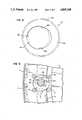
- FIG. 4is a plan view of the part shown in FIG. 3;
- FIG. 5is a plan view of a carrier with a restraining means
- FIG. 6is a fragmentary plan view of the carrier in operation
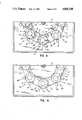
- FIG. 7is a plan view showing another example of the carrier with a restraining means
- FIG. 8is a fragmentary plan view of the carrier of FIG. 7 in operation
- FIG. 9is a plan view showing still another example of the carrier with a restraining means.
- FIG. 10is a plan view showing part of another embodiment of the flat lapping machine according to the present invention.
- FIGS. 1 and 2indicated at 1 is a machine frame of the flat lapping machine, at 2 and 3 are upper and lower lapping plates, and at 4 is a center gear.
- the lapping plates 2 and 3 and center gear 4are connected to a drive source, not shown, through sprockets 5a, 6a and 7a which are mounted at the lower ends of coaxial drive shafts 5 to 7, respectively, to rotate them at an arbitrary speed and in an arbitrary direction.
- the upper plate 2is vertically movably supported on the drive shaft 5.
- the support gear mechanism 10consists of a plural number of small gears 11 to 14 which are located circularly in spaced positions around and in engagement with a carrier 9.
- the small gears 11 to 14are also in engagement with the center gear 4 to constitute a small drive gear through which the carrier 9 is driven from the center gear 4.
- the small gear 14 which is located on the side of the center gear 4is formed in a smaller diameter than other small gears to prevent its contact with the center gear 4.
- the carrier 9which is supported by the above-described support gear mechanism 10 retains therein a work 15 to be lapped by the upper and lower plates 2 and 3, holding the work in a work retaining pocket 16 which is formed in an eccentric position.
- the work 15 which is retained in the work retaining pocket 16is turned along a circle having a radius corresponding to the eccentric distance.
- each carrier 9is supported in a predetermined position and rotated by the small drive gear 11, and the work in its eccentric work holder 16 is turned around a circle having a radius corresponding to the eccentric distance as it is lapped by the upper and lower plates 2 and 3.
- the rotation of the center gearis reversed to rotate the carriers 9 in the opposite direction, thereby reversing the rotation of the works 15, namely, the direction of sliding contact of the works 15 with the lapping plates 2 and 3.
- the center gear 4 and the upper and lower lapping plates 2 and 3are stopped, and then the upper lapping plate 2 is lifted up to the position indicated in phantom in FIG. 1 to unload the works 9 from the carriers 9.
- the works 15may be unloaded separately from or together with the carriers 9. Since the carrier are maintained constantly in predetermined positions without revolving around the center gear 4 and, since the respective carriers 9 lie in the same direction with respect to the center of the center gear 4, they can be stopped in the same direction easily by the use of a suitable detecting means which is adapted to detect the rotational angle of the center gear 4 and to stop same at a certain predetermined rotational angle. Accordingly, loading and unloading of the carriers 9 and works 15 can be faciliated to a marked degree. Especially, automation of the work loading and unloading operations can be realized easily since there is no necessity for adjusting each time the positions and directions of the carriers.
- a center gear 4which is formed with n (integer) times greater number of teeth than the carriers 9 and which is provided with an n-number of dogs (not shown) thereon or on its drive shaft 7 at uniform intervals for cooperation with a dog detector which is mounted oppositely in a suitable position on the machine frame 1.
- the carriers 9can be turned off regularly in a predetermined direction by stopping the center gear 4 at a predetermined angular position through the dog detection.
- carriers 9 with circular work retaining pocketsare used in the above-described embodiment, it is preferable to employ carriers with work restraining means as shown in FIGS. 5 and 6 for the purpose of preventing works 15 from floating up with the upper lapping plate 2 when the latter is lifted up.
- FIG. 5Illustrated in FIG. 5 is a carrier 19 which is provided with a gear 19b around the circumference of its body 19a with a work retaining pocket 20 in an eccentric position
- the work retaining hole 20is provided with a work restraining means constituted by tapered portions 20a which are formed in part of the work retaining pocket 20 to hold a work 15 therein in a restrained state.
- the work 15 on the carrier 19is held in a restrained state in the following manner.
- the upper and lower lapping plates 2 and 3 and the center gear 4are stopped as shown in FIG. 6, stopping the carriers 19 in such positions that the tapered portions 20a of the respective work retaining pocket 20 lie in the circumferential direction of the plates 2 and 3.
- a carrier 22which is provided with a gear 22b around the circumference of its body 22a and formed with a work retaining pocket 23 in an eccentric position.
- the carrier body 22ais provided with a transverse split groove 24 at one side, which joins at its inner end with the work retaining pocket 23.
- the opposing edges of the slit 24are in the form of a dovetail groove 25 and a dovetail projection 26, respectively.
- the dovetail groove 25has slightly greater dimensions than the dovetail projection 26 to permit elastic deformation of the carrier body 22a within a range in which the dovetail projection 26 is displaceable within the dovetail groove 25.
- the work retaining pocket 23is expanded or contracted to release or restrain the work 15 in the pocket.
- a circular notch 27is formed on the carrier body in a radially opposite position with respect to the split groove 24 to prevent cracking of the carrier body which may be caused by concentration of stress at that position as a result of the elastic deformation.
- the lapping operation using the carriers 22is as follows. As shown particularly in FIG. 8, all of the carriers 22 are mounted on the respective support gear mechanisms 10 in such a manner that they are supported in the same direction, and the center gear 4 is rotated in the direction of arrow a to lapp the works 15 which are retained on the carriers 22. During the lapping operation, unnecessary expansion of the carrriers 22 with the split groove 24 is prevented by engagement of the dovetail groove 25 and dovetail projection 26, which limit the expansion of the carriers 22 to an extremely small width which will not impair normal lapping operation.
- the center gear 4is rotated in the reverse direction as indicated by arrow b while holding at least one of the small gears 12 and 13 stationary, whereupon the carrier 22 undergoes elastic deformation to narrow the split groove 24, restraining the work 15 in position by contraction of the work retaining pocket 23.
- the work 15can be relieved of the restraining action simply by rotating the center gear 4 slightly in the direction of arrow a.
- FIG. 9Shown in FIG. 9 is a carrier 30 which is provided with a plural number of work retaining pockets 31 formed on its body 30. These work retaining pockets 31 are successively connected by slit-like grooves 32, and a radial split groove 33 is extended and connected to one of the grooves 32. The opposing edges of the split groove 33 are engaged with each other through a dovetail groove 34 and a dovetail projection 35.
- the groove 32 which is located on the side remote from the split groove 33is provided with a bridge portion 36 connecting an inner portion 30a, which is defined by the work retaining pockets 31 and grooves 32, with an outer portion 30b of the carrier body 30.
- FIG. 10illustrates a further embodiment of the lapping machine of the invention, which is substantially same as the embodiment of FIG. 1 except that each support gear mechanism 40 is constituted by a pair of small gears 41 and 42 and each one of the carriers 9 is meshed directly with the center gear 4. Therefore, works are lapped substantially in the same manner as in the embodiment of FIG. 1.
Landscapes
- Engineering & Computer Science (AREA)
- Mechanical Engineering (AREA)
- Finish Polishing, Edge Sharpening, And Grinding By Specific Grinding Devices (AREA)
- Mechanical Treatment Of Semiconductor (AREA)
Abstract
Description
Claims (16)
Applications Claiming Priority (6)
| Application Number | Priority Date | Filing Date | Title |
|---|---|---|---|
| JP1985117510UJPS6225149U (en) | 1985-07-31 | 1985-07-31 | |
| JP1985117509UJPS6225148U (en) | 1985-07-31 | 1985-07-31 | |
| JP60-117509[U]JPX | 1985-07-31 | ||
| JP60-117510[U] | 1985-07-31 | ||
| JP2970586AJPS62188658A (en) | 1986-02-13 | 1986-02-13 | Surface grinding device |
| JP61033378AJPH0798303B2 (en) | 1986-02-18 | 1986-02-18 | Flat polishing machine |
Publications (1)
| Publication Number | Publication Date |
|---|---|
| US4805348Atrue US4805348A (en) | 1989-02-21 |
Family
ID=27459108
Family Applications (1)
| Application Number | Title | Priority Date | Filing Date |
|---|---|---|---|
| US06/891,241Expired - Fee RelatedUS4805348A (en) | 1985-07-31 | 1986-07-29 | Flat lapping machine |
Country Status (4)
| Country | Link |
|---|---|
| US (1) | US4805348A (en) |
| KR (1) | KR890003776B1 (en) |
| CH (1) | CH670416A5 (en) |
| DE (2) | DE3644854A1 (en) |
Cited By (42)
| Publication number | Priority date | Publication date | Assignee | Title |
|---|---|---|---|---|
| WO1990014926A1 (en)* | 1989-05-31 | 1990-12-13 | Moore Steven C | Ultra-precision lapping apparatus |
| US5123218A (en)* | 1990-02-02 | 1992-06-23 | Speedfam Corporation | Circumferential pattern finishing method |
| WO1995000291A1 (en)* | 1993-06-24 | 1995-01-05 | Carman Charles M Jr | Ultra-precision lapping apparatus |
| US5562530A (en)* | 1994-08-02 | 1996-10-08 | Sematech, Inc. | Pulsed-force chemical mechanical polishing |
| US5697832A (en)* | 1995-10-18 | 1997-12-16 | Cerion Technologies, Inc. | Variable speed bi-directional planetary grinding or polishing apparatus |
| US5733171A (en)* | 1996-07-18 | 1998-03-31 | Speedfam Corporation | Apparatus for the in-process detection of workpieces in a CMP environment |
| US5769691A (en)* | 1996-06-14 | 1998-06-23 | Speedfam Corp | Methods and apparatus for the chemical mechanical planarization of electronic devices |
| US5779203A (en)* | 1996-06-28 | 1998-07-14 | Edlinger; Erich | Adjustable wafer cassette stand |
| US5783497A (en)* | 1994-08-02 | 1998-07-21 | Sematech, Inc. | Forced-flow wafer polisher |
| US5842912A (en)* | 1996-07-15 | 1998-12-01 | Speedfam Corporation | Apparatus for conditioning polishing pads utilizing brazed diamond technology |
| US5872633A (en)* | 1996-07-26 | 1999-02-16 | Speedfam Corporation | Methods and apparatus for detecting removal of thin film layers during planarization |
| US5899216A (en)* | 1996-07-08 | 1999-05-04 | Speedfam Corporation | Apparatus for rinsing wafers in the context of a combined cleaning rinsing and drying system |
| US5938506A (en)* | 1997-06-03 | 1999-08-17 | Speedfam-Ipec Corporation | Methods and apparatus for conditioning grinding stones |
| US5950327A (en)* | 1996-07-08 | 1999-09-14 | Speedfam-Ipec Corporation | Methods and apparatus for cleaning and drying wafers |
| US5957763A (en)* | 1997-09-19 | 1999-09-28 | Speedfam Corporation | Polishing apparatus with support columns supporting multiple platform members |
| US5961369A (en)* | 1996-07-18 | 1999-10-05 | Speedfam-Ipec Corp. | Methods for the in-process detection of workpieces with a monochromatic light source |
| US5967881A (en)* | 1997-05-29 | 1999-10-19 | Tucker; Thomas N. | Chemical mechanical planarization tool having a linear polishing roller |
| US5975986A (en)* | 1997-08-08 | 1999-11-02 | Speedfam-Ipec Corporation | Index table and drive mechanism for a chemical mechanical planarization machine |
| US6030280A (en)* | 1997-07-23 | 2000-02-29 | Speedfam Corporation | Apparatus for holding workpieces during lapping, honing, and polishing |
| US6033521A (en)* | 1997-06-04 | 2000-03-07 | Speedfam-Ipec Corporation | Tilt mechanism for wafer cassette |
| US6113465A (en)* | 1998-06-16 | 2000-09-05 | Speedfam-Ipec Corporation | Method and apparatus for improving die planarity and global uniformity of semiconductor wafers in a chemical mechanical polishing context |
| US6168506B1 (en)* | 1998-01-21 | 2001-01-02 | Speedfam-Ipec Corporation | Apparatus for polishing using improved plate supports |
| US6213855B1 (en) | 1999-07-26 | 2001-04-10 | Speedfam-Ipec Corporation | Self-powered carrier for polishing or planarizing wafers |
| US6217410B1 (en) | 1996-07-26 | 2001-04-17 | Speedfam-Ipec Corporation | Apparatus for cleaning workpiece surfaces and monitoring probes during workpiece processing |
| US6280296B1 (en)* | 1998-12-02 | 2001-08-28 | Noritake Co., Ltd. | Surface polishing method and apparatus wherein axis of autorotation of workpiece is revolved about an axis within circumscribed circle of the workpiece |
| US6296553B1 (en)* | 1997-04-02 | 2001-10-02 | Nippei Toyama Corporation | Grinding method, surface grinder, workpiece support, mechanism and work rest |
| US6338672B1 (en)* | 1998-12-21 | 2002-01-15 | White Hydraulics, Inc. | Dressing wheel system |
| US6497613B1 (en) | 1997-06-26 | 2002-12-24 | Speedfam-Ipec Corporation | Methods and apparatus for chemical mechanical planarization using a microreplicated surface |
| US6517424B2 (en) | 2000-03-10 | 2003-02-11 | Abrasive Technology, Inc. | Protective coatings for CMP conditioning disk |
| US6708234B2 (en) | 2000-09-29 | 2004-03-16 | Ricoh Company, Ltd. | Data processing apparatus and DMA data transfer method |
| DE19781822B4 (en)* | 1996-07-08 | 2004-09-09 | Speedfam-Ipec Corp.(N.D.Ges.D.Staates Delaware), Chandler | Cleaning station for use in a system for cleaning, rinsing and drying semiconductor wafers |
| US20040173307A1 (en)* | 2001-11-12 | 2004-09-09 | Samsung Electronics Co., Ltd. | Apparatus and method for supplying chemicals in chemical mechanical polishing systems |
| US20040191045A1 (en)* | 2001-07-28 | 2004-09-30 | Dieter Leuhmann | Hand-operated tool |
| US6932684B1 (en) | 2004-03-08 | 2005-08-23 | Roy H. Hunt | Reciprocal blade lapping machine |
| US20060128276A1 (en)* | 2004-12-10 | 2006-06-15 | Sumco Corporation | Carrier for double side polishing |
| US7399217B1 (en) | 2007-02-05 | 2008-07-15 | P.R. Hoffman Machine Products | Lapping machine |
| US20110097977A1 (en)* | 2009-08-07 | 2011-04-28 | Abrasive Technology, Inc. | Multiple-sided cmp pad conditioning disk |
| CN102909620A (en)* | 2012-10-24 | 2013-02-06 | 常熟天地煤机装备有限公司 | Universal type pitch circle positioning gear mill inner hole device |
| US20130084783A1 (en)* | 2011-09-30 | 2013-04-04 | Sony Corporation | Grinding apparatus and grinding method |
| US11052506B2 (en)* | 2015-10-09 | 2021-07-06 | Sumco Corporation | Carrier ring, grinding device, and grinding method |
| US20240337010A1 (en)* | 2023-04-06 | 2024-10-10 | Vacuum Innovations LLC | Planetary rotation system with lunar rotation |
| US12442071B2 (en)* | 2024-04-04 | 2025-10-14 | Vacuum Innovations LLC | Planetary rotation system with lunar rotation |
Families Citing this family (3)
| Publication number | Priority date | Publication date | Assignee | Title |
|---|---|---|---|---|
| DE8712995U1 (en)* | 1987-09-14 | 1987-12-03 | Peter Wolters AG, 2370 Rendsburg | Honing, lapping or polishing machine |
| DE3730795A1 (en)* | 1987-09-14 | 1989-03-23 | Wolters Peter Fa | HONING, LAEPPING OR POLISHING MACHINE |
| DE10081456T1 (en) | 1999-05-17 | 2001-09-27 | Kashiwara Machine Mfg | Method and device for double-sided polishing |
Citations (3)
| Publication number | Priority date | Publication date | Assignee | Title |
|---|---|---|---|---|
| US2618911A (en)* | 1950-07-08 | 1952-11-25 | Norton Co | Lapping machine |
| JPS56157035A (en)* | 1980-05-09 | 1981-12-04 | Nec Corp | Simultaneous working of both faces of wafer |
| JPS56157036A (en)* | 1980-05-09 | 1981-12-04 | Nec Corp | Simultaneous working of both faces of wafer |
Family Cites Families (4)
| Publication number | Priority date | Publication date | Assignee | Title |
|---|---|---|---|---|
| DE965190C (en)* | 1952-09-14 | 1957-06-06 | Wolters Peter Fa | Device for flat lapping or flat grinding |
| DE1792521U (en)* | 1958-10-28 | 1959-07-23 | Hahn & Kolb | LAEPING MACHINE WITH A PLANET LAEPING DEVICE. |
| DE2403574C2 (en)* | 1974-01-25 | 1983-10-27 | Moskovskoe ordena Lenina i ordena Trudovogo krasnogo znameni vysšee techničeskoe učilišče imeni N.E. Baumana, Moskva | Lapping machine |
| JPS5981057A (en)* | 1982-11-01 | 1984-05-10 | Hitachi Ltd | Double-sided polishing device |
- 1986
- 1986-07-23DEDE19863644854patent/DE3644854A1/enactiveGranted
- 1986-07-23DEDE19863624878patent/DE3624878A1/enactiveGranted
- 1986-07-29KRKR1019860006184Apatent/KR890003776B1/ennot_activeExpired
- 1986-07-29USUS06/891,241patent/US4805348A/ennot_activeExpired - Fee Related
- 1986-07-29CHCH3040/86Apatent/CH670416A5/denot_activeIP Right Cessation
Patent Citations (3)
| Publication number | Priority date | Publication date | Assignee | Title |
|---|---|---|---|---|
| US2618911A (en)* | 1950-07-08 | 1952-11-25 | Norton Co | Lapping machine |
| JPS56157035A (en)* | 1980-05-09 | 1981-12-04 | Nec Corp | Simultaneous working of both faces of wafer |
| JPS56157036A (en)* | 1980-05-09 | 1981-12-04 | Nec Corp | Simultaneous working of both faces of wafer |
Cited By (50)
| Publication number | Priority date | Publication date | Assignee | Title |
|---|---|---|---|---|
| WO1990014926A1 (en)* | 1989-05-31 | 1990-12-13 | Moore Steven C | Ultra-precision lapping apparatus |
| US5123218A (en)* | 1990-02-02 | 1992-06-23 | Speedfam Corporation | Circumferential pattern finishing method |
| WO1995000291A1 (en)* | 1993-06-24 | 1995-01-05 | Carman Charles M Jr | Ultra-precision lapping apparatus |
| US5783497A (en)* | 1994-08-02 | 1998-07-21 | Sematech, Inc. | Forced-flow wafer polisher |
| US5562530A (en)* | 1994-08-02 | 1996-10-08 | Sematech, Inc. | Pulsed-force chemical mechanical polishing |
| US5697832A (en)* | 1995-10-18 | 1997-12-16 | Cerion Technologies, Inc. | Variable speed bi-directional planetary grinding or polishing apparatus |
| US5769691A (en)* | 1996-06-14 | 1998-06-23 | Speedfam Corp | Methods and apparatus for the chemical mechanical planarization of electronic devices |
| US7083501B1 (en) | 1996-06-14 | 2006-08-01 | Speedfam-Ipec Corporation | Methods and apparatus for the chemical mechanical planarization of electronic devices |
| US5779203A (en)* | 1996-06-28 | 1998-07-14 | Edlinger; Erich | Adjustable wafer cassette stand |
| US5950327A (en)* | 1996-07-08 | 1999-09-14 | Speedfam-Ipec Corporation | Methods and apparatus for cleaning and drying wafers |
| US5899216A (en)* | 1996-07-08 | 1999-05-04 | Speedfam Corporation | Apparatus for rinsing wafers in the context of a combined cleaning rinsing and drying system |
| DE19781822B4 (en)* | 1996-07-08 | 2004-09-09 | Speedfam-Ipec Corp.(N.D.Ges.D.Staates Delaware), Chandler | Cleaning station for use in a system for cleaning, rinsing and drying semiconductor wafers |
| US5842912A (en)* | 1996-07-15 | 1998-12-01 | Speedfam Corporation | Apparatus for conditioning polishing pads utilizing brazed diamond technology |
| US5961369A (en)* | 1996-07-18 | 1999-10-05 | Speedfam-Ipec Corp. | Methods for the in-process detection of workpieces with a monochromatic light source |
| US5993289A (en)* | 1996-07-18 | 1999-11-30 | Speedfam-Ipec Corporation | Methods for the in-process detection of workpieces in a CMP environment |
| US5733171A (en)* | 1996-07-18 | 1998-03-31 | Speedfam Corporation | Apparatus for the in-process detection of workpieces in a CMP environment |
| US6217410B1 (en) | 1996-07-26 | 2001-04-17 | Speedfam-Ipec Corporation | Apparatus for cleaning workpiece surfaces and monitoring probes during workpiece processing |
| US5872633A (en)* | 1996-07-26 | 1999-02-16 | Speedfam Corporation | Methods and apparatus for detecting removal of thin film layers during planarization |
| US6296553B1 (en)* | 1997-04-02 | 2001-10-02 | Nippei Toyama Corporation | Grinding method, surface grinder, workpiece support, mechanism and work rest |
| US5967881A (en)* | 1997-05-29 | 1999-10-19 | Tucker; Thomas N. | Chemical mechanical planarization tool having a linear polishing roller |
| US5938506A (en)* | 1997-06-03 | 1999-08-17 | Speedfam-Ipec Corporation | Methods and apparatus for conditioning grinding stones |
| US6033521A (en)* | 1997-06-04 | 2000-03-07 | Speedfam-Ipec Corporation | Tilt mechanism for wafer cassette |
| US6190118B1 (en) | 1997-06-04 | 2001-02-20 | Speedfam-Ipec Corporation | Tilt mechanism for wafer cassette |
| US6497613B1 (en) | 1997-06-26 | 2002-12-24 | Speedfam-Ipec Corporation | Methods and apparatus for chemical mechanical planarization using a microreplicated surface |
| US6030280A (en)* | 1997-07-23 | 2000-02-29 | Speedfam Corporation | Apparatus for holding workpieces during lapping, honing, and polishing |
| US5975986A (en)* | 1997-08-08 | 1999-11-02 | Speedfam-Ipec Corporation | Index table and drive mechanism for a chemical mechanical planarization machine |
| US6001005A (en)* | 1997-09-19 | 1999-12-14 | Speedfam Corporation | Polishing apparatus |
| US5957763A (en)* | 1997-09-19 | 1999-09-28 | Speedfam Corporation | Polishing apparatus with support columns supporting multiple platform members |
| US6168506B1 (en)* | 1998-01-21 | 2001-01-02 | Speedfam-Ipec Corporation | Apparatus for polishing using improved plate supports |
| US6113465A (en)* | 1998-06-16 | 2000-09-05 | Speedfam-Ipec Corporation | Method and apparatus for improving die planarity and global uniformity of semiconductor wafers in a chemical mechanical polishing context |
| US6280296B1 (en)* | 1998-12-02 | 2001-08-28 | Noritake Co., Ltd. | Surface polishing method and apparatus wherein axis of autorotation of workpiece is revolved about an axis within circumscribed circle of the workpiece |
| DE19957797B4 (en)* | 1998-12-02 | 2013-05-29 | Noritake Co., Ltd. | Surface polishing method and apparatus |
| US6338672B1 (en)* | 1998-12-21 | 2002-01-15 | White Hydraulics, Inc. | Dressing wheel system |
| US7101264B2 (en) | 1998-12-21 | 2006-09-05 | White Drive Products, Inc. | Dressing wheel system |
| US6213855B1 (en) | 1999-07-26 | 2001-04-10 | Speedfam-Ipec Corporation | Self-powered carrier for polishing or planarizing wafers |
| US6517424B2 (en) | 2000-03-10 | 2003-02-11 | Abrasive Technology, Inc. | Protective coatings for CMP conditioning disk |
| US6708234B2 (en) | 2000-09-29 | 2004-03-16 | Ricoh Company, Ltd. | Data processing apparatus and DMA data transfer method |
| US20040191045A1 (en)* | 2001-07-28 | 2004-09-30 | Dieter Leuhmann | Hand-operated tool |
| US20040173307A1 (en)* | 2001-11-12 | 2004-09-09 | Samsung Electronics Co., Ltd. | Apparatus and method for supplying chemicals in chemical mechanical polishing systems |
| US6814835B2 (en) | 2001-11-12 | 2004-11-09 | Samsung Electronics Co., Ltd. | Apparatus and method for supplying chemicals in chemical mechanical polishing systems |
| US6932684B1 (en) | 2004-03-08 | 2005-08-23 | Roy H. Hunt | Reciprocal blade lapping machine |
| US20060128276A1 (en)* | 2004-12-10 | 2006-06-15 | Sumco Corporation | Carrier for double side polishing |
| US7399217B1 (en) | 2007-02-05 | 2008-07-15 | P.R. Hoffman Machine Products | Lapping machine |
| US20080188166A1 (en)* | 2007-02-05 | 2008-08-07 | Godshall Mark A | Lapping machine |
| US20110097977A1 (en)* | 2009-08-07 | 2011-04-28 | Abrasive Technology, Inc. | Multiple-sided cmp pad conditioning disk |
| US20130084783A1 (en)* | 2011-09-30 | 2013-04-04 | Sony Corporation | Grinding apparatus and grinding method |
| CN102909620A (en)* | 2012-10-24 | 2013-02-06 | 常熟天地煤机装备有限公司 | Universal type pitch circle positioning gear mill inner hole device |
| US11052506B2 (en)* | 2015-10-09 | 2021-07-06 | Sumco Corporation | Carrier ring, grinding device, and grinding method |
| US20240337010A1 (en)* | 2023-04-06 | 2024-10-10 | Vacuum Innovations LLC | Planetary rotation system with lunar rotation |
| US12442071B2 (en)* | 2024-04-04 | 2025-10-14 | Vacuum Innovations LLC | Planetary rotation system with lunar rotation |
Also Published As
| Publication number | Publication date |
|---|---|
| DE3624878A1 (en) | 1987-02-12 |
| DE3624878C2 (en) | 1988-11-03 |
| DE3644854A1 (en) | 1987-07-30 |
| CH670416A5 (en) | 1989-06-15 |
| KR890003776B1 (en) | 1989-10-04 |
| DE3644854C2 (en) | 1988-04-21 |
| KR870001002A (en) | 1987-03-10 |
Similar Documents
| Publication | Publication Date | Title |
|---|---|---|
| US4805348A (en) | Flat lapping machine | |
| US5690542A (en) | Disc streak pattern forming method and apparatus | |
| US4773185A (en) | Surface abrading machine | |
| US3818640A (en) | Work carrier drive for double disc grinder with reversible drive and automatic stop means | |
| US4157637A (en) | Planetary-type lapping machine for lapping a group of workpieces | |
| JPS62188658A (en) | Surface grinding device | |
| JP4242034B2 (en) | Polishing method and polishing apparatus | |
| JP5265281B2 (en) | Double-side polishing equipment | |
| JP3942956B2 (en) | Inclined surface polishing machine | |
| US2308512A (en) | Grinding machine | |
| US3731436A (en) | Free abrasive machine | |
| JPH0222213Y2 (en) | ||
| JPH0798303B2 (en) | Flat polishing machine | |
| JPH1133900A (en) | Surface grinding device | |
| JPH0413083Y2 (en) | ||
| JPS60155357A (en) | Surface machining device | |
| JPH0650126Y2 (en) | Medium surface plate for surface plate correction in lapping machine | |
| JPS6210778B2 (en) | ||
| JPH01252356A (en) | Both sides grinding machine | |
| JPS6031627B2 (en) | Double-sided polishing device | |
| JPS6219983B2 (en) | ||
| JPH11859A (en) | Polishing method and polishing apparatus | |
| JPS63312059A (en) | Surface polishing device | |
| JPH0232111B2 (en) | ||
| JPH02145253A (en) | Selfcorrection of lapping machine |
Legal Events
| Date | Code | Title | Description |
|---|---|---|---|
| AS | Assignment | Owner name:SPEEDFAM CO., LTD., A CORP OF JAPAN Free format text:ASSIGNMENT OF ASSIGNORS INTEREST.;ASSIGNORS:ARAI, HATSUYUKI;NAGAHASHI, ISAO;MAEDA, SEIICHI;AND OTHERS;REEL/FRAME:004602/0316 Effective date:19860716 Owner name:SPEEDFAM CO., LTD., A CORP OF JAPAN, STATELESS Free format text:ASSIGNMENT OF ASSIGNORS INTEREST;ASSIGNORS:ARAI, HATSUYUKI;NAGAHASHI, ISAO;MAEDA, SEIICHI;AND OTHERS;REEL/FRAME:004602/0316 Effective date:19860716 | |
| FEPP | Fee payment procedure | Free format text:PAT HOLDER CLAIMS SMALL ENTITY STATUS - SMALL BUSINESS (ORIGINAL EVENT CODE: SM02); ENTITY STATUS OF PATENT OWNER: SMALL ENTITY | |
| REFU | Refund | Free format text:REFUND OF EXCESS PAYMENTS PROCESSED (ORIGINAL EVENT CODE: R169); ENTITY STATUS OF PATENT OWNER: SMALL ENTITY | |
| FEPP | Fee payment procedure | Free format text:PAT HLDR NO LONGER CLAIMS SMALL ENT STAT AS SMALL BUSINESS (ORIGINAL EVENT CODE: LSM2); ENTITY STATUS OF PATENT OWNER: SMALL ENTITY | |
| FPAY | Fee payment | Year of fee payment:4 | |
| REMI | Maintenance fee reminder mailed | ||
| LAPS | Lapse for failure to pay maintenance fees | ||
| FP | Lapsed due to failure to pay maintenance fee | Effective date:19970226 | |
| AS | Assignment | Owner name:SPEEDFAM-IPEC CORPORATION, ARIZONA Free format text:MERGER;ASSIGNOR:SPEEDFAM CORPORATION;REEL/FRAME:010078/0150 Effective date:19990526 | |
| STCH | Information on status: patent discontinuation | Free format text:PATENT EXPIRED DUE TO NONPAYMENT OF MAINTENANCE FEES UNDER 37 CFR 1.362 |