US4805170A - Data communication network - Google Patents
Data communication networkDownload PDFInfo
- Publication number
- US4805170A US4805170AUS07/043,771US4377187AUS4805170AUS 4805170 AUS4805170 AUS 4805170AUS 4377187 AUS4377187 AUS 4377187AUS 4805170 AUS4805170 AUS 4805170A
- Authority
- US
- United States
- Prior art keywords
- node
- data
- network
- write
- transmission path
- Prior art date
- Legal status (The legal status is an assumption and is not a legal conclusion. Google has not performed a legal analysis and makes no representation as to the accuracy of the status listed.)
- Expired - Lifetime
Links
Images

Classifications
- H—ELECTRICITY
- H04—ELECTRIC COMMUNICATION TECHNIQUE
- H04L—TRANSMISSION OF DIGITAL INFORMATION, e.g. TELEGRAPHIC COMMUNICATION
- H04L12/00—Data switching networks
- H04L12/28—Data switching networks characterised by path configuration, e.g. LAN [Local Area Networks] or WAN [Wide Area Networks]
- H04L12/42—Loop networks
- H04L12/427—Loop networks with decentralised control
- H04L12/433—Loop networks with decentralised control with asynchronous transmission, e.g. token ring, register insertion
Definitions
- the inventionrelates to communication networks.
- Data systemsuse communication networks to exchange data.
- a communication networkhereinafter called network
- Some networksare arranged such that one node may continuously write data onto the network thereby preventing other nodes from gaining access to the network.
- Other networksuse token data that is continuously transmitted on the transmission paths to sequentially arrive at each node. The token data arrival enables a node having write data to write the write data onto the network.
- a problemarises in that the data traffic handling capacity of such networks are limited in that nodes are prevented from writing data onto the network until the one node ceases to write data onto the network or until each node receives the token data.
- nodeshaving apparatus responsive to receiving a predefined data signal continuously transmitted on the network and counting the predefined data signal a predetermined number of times to control node access to the network such that multiple nodes may mutually write data onto the network proportional to the network data traffic independent of the network location of the predefined data signal.
- the illustrative communication networkhas nodes interconnected by transmission paths on which a predefined data signal is continuously transmitted to sequentially reach each node.
- the network structure and method of operationdetects the receipt of the predefined data signal at each node and counts the number of times that the predefined data signal is detected by the node.
- Node signal generating apparatusgenerates signals in response to the nodes having counted a predetermined number of the detected predefined data signals and selectively controls the nodes so that multiple nodes may mutually write data onto the network in proportion to the network data traffic and independent of the network location of the predefined data signal.
- FIG. 1is a block diagram of a network embodying the principles of the invention.
- FIG. 2illustrates the functional apparatus relationship of a network node of the network set forth in FIG. 1.
- Network 1 of FIG. 1has transmission paths 15 interconnecting nodes 10 each connected by a bus 13 to a node processor 11 and a line interface unit 12. Data incoming to node 10 on data link 14 is entered by line interface unit 12 onto bus 13 and processed by node processor 11 into write data which is stored in write store 104. Subsequently, write store 104 writes the stored write data, via switch 102, onto a transmission path 15 outgoing from node 10. Data written onto network 1 is transmitted on transmission paths 15 from node to node.
- Data received by a node 10 on incoming transmission path 15is stored in header store 105. If intended for another node 10, the received data is stored, via switch 101, in propagate store 100 and subsequently transmitted, via switch 102, on a transmission path 15 outgoing from node 10.
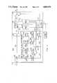
- address detector 1061 of node controller variable gate generator 106FIG. 2
- End of message detector 1062resets read logic 1064 to enable switch 101, via lead 10641, to connect header store 105 through transmission path 1051 with propagate store 100 which in turn is coupled with outgoing transmission path 15 through transmission path 10026 and switch 102.
- Read datais read from read store 103, onto bus 13 into node processor 11, FIG. 1, and transmitted via line interface unit 12 onto a data link 14.
- Each node 10can write data stored in write store 104 onto network 1 concurrently with other nodes 10 which are also writing data onto network 1.
- a predefined data signalis continuously transmitted on transmission paths 15 to sequentially reach each node 10.
- the predefined data signal incoming to a node 10is temporarily stored in header store 105.
- Gate detector 1060FIG. 2, detects the presence of the predefined data signal stored in header store 105 and advances gate counter 1063 one count. If gate counter 1063 has counted a total count less than or equal to a predetermined number, for example two, register 1065 remains in an inoperative state thereby inhibiting operation of AND gate 1067.
- write logic 1068With AND gate 1067 inhibited, write logic 1068 remains in a reset state thereby enabling switch 102 to continue connecting propagate store 100, via transmission path 10026, with outgoing transmission path 15.
- the predefined data signalis subsequently transmitted from header store 105, via transmission paths 1051, 1010, 10026; switches 101, 102; and propagate store 100, onto outgoing transmission path 15.
- Node 10may have write data recorded in write store 104 at this time, however node 10 is delayed in writing the write data onto network 1 until node controller variable gate generator 106 has counted the predetermined number of the detected predefined data signals.
- the predefined data signalcontinues to be transmitted on transmission paths 15 between nodes 10.
- the time that it takes the predefined data signal to return to a node 10depends upon the amount of data traffic being handled by network 1. If there is a small amount of data traffic, the predefined data signal will return to a node 10 in a short period of time. When there is a large amount of data traffic, the time period increases as to when the predefined data signal returns to a node 10.
- gate detector 1060again detects the presence of the predefined data signal in header store 105 and advances gate counter 1063.
- register 1065detects the predetermined number of times that node 10 has detected the predefined data signal
- register 1065enables an input of AND gate 1067 via lead 10657. If node 10 has not received any write data over buses 13 and 134, write store 104 is empty thereby inhibiting operation of AND gate 1067 via lead 10467.
- the predefined data signalis thereby transmitted via transmission paths 1051, 1010, 10026; switches 101, 102; and propagate store 100 from node 10 on out-going transmission path 15.
- idle detector 1066When propagate store 100 is transmitting node received data on transmission path 10026, idle detector 1066 resets idle logic 1069 to record an active state thereby inhibiting an input of AND gate 1067 via lead 10697. After transmission of received data on transmission path 10026, idle detector 1066 sets idle logic 1069 to record an idle state enabling an input of AND gate 1067.
- Write store 104when empty of write data, maintains a signal on lead 10467 to inhibit operation of AND gate 1067.
- data received at node 10 on incoming transmission path 15is transmitted from node 10 on outgoing transmission path 15 in that switch 102 is enabled by write logic 1068 to connect propagate store 100 through transmission path 10026 with outgoing transmission path 15.
- write store 104Upon receipt of write data, write store 104 enables an input of AND gate 1067 via lead 10467 to indicate that node 10 has stored write data to be written onto network 1.
- AND gate 1067responds to the idle state recorded by idle logic 1069 and to an indication on lead 10467 that write store 104 has received write data by generating a signal setting write logic 1068 to enable switch 102 to disconnect outgoing transmission path 15 from propagate store 100 and connect it to write store 104 via transmission path 1042 when register 1065 has recorded the predetermined number of times that the predefined data signal has been detected by node 10.
- the AND gate 1067 generated signalenables lead 10673 to initialize gate counter 1063 to return to the initial count of zero.
- Node 10then proceeds to write the stored write data from write store 104 onto network 1 over transmission path 1042 through switch 102 onto outgoing transmission path 15.
- write store 104Upon detecting the end of the write data, write store 104 enables lead 10468 to reset write logic 1068 to enable switch 102 to disconnect write store 104 from outgoing transmission path 15 which is then reconnected to propagate store 100.
- Node 10temporarily stores data received on incoming transmission path 15 in propagate store 100 as write data is being written from write store 104 onto outgoing transmission path 15.
- switch 102reconnects propagate store 100 with outgoing transmission path 15, propagate store 100 transmits the stored received data onto outgoing transmission path 15.
- Node controller variable gate generator 106enables multiple nodes 10 to access and mutually write data onto network 10 proportional to the network data traffic.
- the methodcomprises detecting a predefined data signal that is continuously transmitted on the network to sequentially reach each node 10 and counting the number of the times the predefined data signal is detected by a node 10.
- the methodfurther generates gate signals at nodes 10 in response to having counted a predetermined number of the detected predefined data signals to control nodes 10 such that multiple nodes 10 may access and mutually write data onto network 1 independent of the network location of the predefined data signal.
- Data traffic on network 1determines the amount of time it takes the predefined data signal to reach each node 10. When data traffic is heavy, it takes a longer period of time for the predefined data signal to reach each node 10 and less time when data traffic is light.
- Node controller variable gate generator 106responds to a predetermined number of detected predefined data signals by generating gate signals on lead 10657 that vary in time in accordance with the amount of data traffic on network 1. The generated signals control node 10 access to network 1 and since each node 10 is provided with node controller variable gate generator 106, then multiple ones of nodes 10 may mutually write data onto network 1 proportional to the network data traffic independent of the network location of the predefined data signal.
Landscapes
- Engineering & Computer Science (AREA)
- Computer Networks & Wireless Communication (AREA)
- Signal Processing (AREA)
- Data Exchanges In Wide-Area Networks (AREA)
- Small-Scale Networks (AREA)
Abstract
Description
Claims (22)
Priority Applications (2)
| Application Number | Priority Date | Filing Date | Title |
|---|---|---|---|
| US07/043,771US4805170A (en) | 1987-04-29 | 1987-04-29 | Data communication network |
| PCT/US1988/000189WO1988008653A1 (en) | 1987-04-29 | 1988-01-25 | Data communication network |
Applications Claiming Priority (1)
| Application Number | Priority Date | Filing Date | Title |
|---|---|---|---|
| US07/043,771US4805170A (en) | 1987-04-29 | 1987-04-29 | Data communication network |
Publications (1)
| Publication Number | Publication Date |
|---|---|
| US4805170Atrue US4805170A (en) | 1989-02-14 |
Family
ID=21928807
Family Applications (1)
| Application Number | Title | Priority Date | Filing Date |
|---|---|---|---|
| US07/043,771Expired - LifetimeUS4805170A (en) | 1987-04-29 | 1987-04-29 | Data communication network |
Country Status (2)
| Country | Link |
|---|---|
| US (1) | US4805170A (en) |
| WO (1) | WO1988008653A1 (en) |
Cited By (9)
| Publication number | Priority date | Publication date | Assignee | Title |
|---|---|---|---|---|
| US4860284A (en)* | 1988-04-20 | 1989-08-22 | American Telephone And Telegraph Company, At&T Bell Laboratories | Method and apparatus for identifying location of a lost token signal in a data communication network |
| US4926418A (en)* | 1989-04-11 | 1990-05-15 | International Business Machines Corporation | Fairness algorithm for full-duplex buffer insertion ring |
| US4933936A (en)* | 1987-08-17 | 1990-06-12 | The United States Of America As Represented By The Administrator Of The National Aeronautics And Space Administration | Distributed computing system with dual independent communications paths between computers and employing split tokens |
| US5296936A (en)* | 1991-07-22 | 1994-03-22 | International Business Machines Corporation | Communication apparatus and method for transferring image data from a source to one or more receivers |
| US5347450A (en)* | 1989-01-18 | 1994-09-13 | Intel Corporation | Message routing in a multiprocessor computer system |
| US5359320A (en)* | 1990-03-29 | 1994-10-25 | Mti Technology Corporation | Method and apparatus for scheduling access to a CSMA communication medium of a node having arbitration circuit |
| US5361063A (en)* | 1990-03-29 | 1994-11-01 | Mti Technology Corporation | Method and apparatus for scheduling access to a CSMA communication medium |
| US5398317A (en)* | 1989-01-18 | 1995-03-14 | Intel Corporation | Synchronous message routing using a retransmitted clock signal in a multiprocessor computer system |
| US6822970B1 (en) | 2000-01-31 | 2004-11-23 | Owens-Brockway Glass Container Inc. | Glassware forming system with star network communication configuration |
Families Citing this family (5)
| Publication number | Priority date | Publication date | Assignee | Title |
|---|---|---|---|---|
| US5235593A (en)* | 1989-12-01 | 1993-08-10 | National Semiconductor Corporation | Ring latency timer |
| EP0430053A3 (en)* | 1989-12-01 | 1992-04-01 | National Semiconductor Corporation | Ring latency timer |
| CA2039059C (en)* | 1990-06-14 | 1997-09-09 | Allen Dennis Fergeson | Communication network node |
| SE466726B (en)* | 1990-08-20 | 1992-03-23 | Kent Lennartsson | DISTRIBUTED COMPUTER SYSTEM DEVICE |
| FI95184C (en)* | 1992-04-16 | 1995-12-27 | Tapio Marttinen | Procedure for transmitting information in digital form |
Citations (9)
| Publication number | Priority date | Publication date | Assignee | Title |
|---|---|---|---|---|
| US31852A (en)* | 1861-03-26 | S J Olmsted | Gate-hinge | |
| US3752932A (en)* | 1971-12-14 | 1973-08-14 | Ibm | Loop communications system |
| USRE31852E (en) | 1967-11-23 | 1985-03-19 | Willemijn Houdstermaatschappij BV | Data transmission system |
| US4517644A (en)* | 1980-09-03 | 1985-05-14 | Hitachi, Ltd. | Symmetry type loop communication system |
| US4554659A (en)* | 1983-12-12 | 1985-11-19 | At&T Bell Laboratories | Data communication network |
| US4566098A (en)* | 1984-05-14 | 1986-01-21 | Northern Telecom Limited | Control mechanism for a ring communication system |
| US4566097A (en)* | 1983-12-23 | 1986-01-21 | International Business Machines Corp. | Token ring with secondary transmit opportunities |
| US4583217A (en)* | 1982-08-20 | 1986-04-15 | U.S. Philips Corporation | Method of access control in a communication system using orthogonal functions |
| US4616359A (en)* | 1983-12-19 | 1986-10-07 | At&T Bell Laboratories | Adaptive preferential flow control for packet switching system |
Family Cites Families (2)
| Publication number | Priority date | Publication date | Assignee | Title |
|---|---|---|---|---|
| US4404557A (en)* | 1982-03-05 | 1983-09-13 | Burroughs Corporation | Timed token ring with multiple priorities |
| GB8417910D0 (en)* | 1984-07-13 | 1984-08-15 | British Telecomm | Communications network |
- 1987
- 1987-04-29USUS07/043,771patent/US4805170A/ennot_activeExpired - Lifetime
- 1988
- 1988-01-25WOPCT/US1988/000189patent/WO1988008653A1/enunknown
Patent Citations (10)
| Publication number | Priority date | Publication date | Assignee | Title |
|---|---|---|---|---|
| US31852A (en)* | 1861-03-26 | S J Olmsted | Gate-hinge | |
| USRE31852E (en) | 1967-11-23 | 1985-03-19 | Willemijn Houdstermaatschappij BV | Data transmission system |
| USRE31852F1 (en) | 1967-11-23 | 1992-10-20 | Data transmission system | |
| US3752932A (en)* | 1971-12-14 | 1973-08-14 | Ibm | Loop communications system |
| US4517644A (en)* | 1980-09-03 | 1985-05-14 | Hitachi, Ltd. | Symmetry type loop communication system |
| US4583217A (en)* | 1982-08-20 | 1986-04-15 | U.S. Philips Corporation | Method of access control in a communication system using orthogonal functions |
| US4554659A (en)* | 1983-12-12 | 1985-11-19 | At&T Bell Laboratories | Data communication network |
| US4616359A (en)* | 1983-12-19 | 1986-10-07 | At&T Bell Laboratories | Adaptive preferential flow control for packet switching system |
| US4566097A (en)* | 1983-12-23 | 1986-01-21 | International Business Machines Corp. | Token ring with secondary transmit opportunities |
| US4566098A (en)* | 1984-05-14 | 1986-01-21 | Northern Telecom Limited | Control mechanism for a ring communication system |
Cited By (10)
| Publication number | Priority date | Publication date | Assignee | Title |
|---|---|---|---|---|
| US4933936A (en)* | 1987-08-17 | 1990-06-12 | The United States Of America As Represented By The Administrator Of The National Aeronautics And Space Administration | Distributed computing system with dual independent communications paths between computers and employing split tokens |
| US4860284A (en)* | 1988-04-20 | 1989-08-22 | American Telephone And Telegraph Company, At&T Bell Laboratories | Method and apparatus for identifying location of a lost token signal in a data communication network |
| US5347450A (en)* | 1989-01-18 | 1994-09-13 | Intel Corporation | Message routing in a multiprocessor computer system |
| US5398317A (en)* | 1989-01-18 | 1995-03-14 | Intel Corporation | Synchronous message routing using a retransmitted clock signal in a multiprocessor computer system |
| US4926418A (en)* | 1989-04-11 | 1990-05-15 | International Business Machines Corporation | Fairness algorithm for full-duplex buffer insertion ring |
| US5359320A (en)* | 1990-03-29 | 1994-10-25 | Mti Technology Corporation | Method and apparatus for scheduling access to a CSMA communication medium of a node having arbitration circuit |
| US5361063A (en)* | 1990-03-29 | 1994-11-01 | Mti Technology Corporation | Method and apparatus for scheduling access to a CSMA communication medium |
| US5485147A (en)* | 1990-03-29 | 1996-01-16 | Mti Technology Corporation | Method and apparatus for scheduling access to a CSMA communication medium |
| US5296936A (en)* | 1991-07-22 | 1994-03-22 | International Business Machines Corporation | Communication apparatus and method for transferring image data from a source to one or more receivers |
| US6822970B1 (en) | 2000-01-31 | 2004-11-23 | Owens-Brockway Glass Container Inc. | Glassware forming system with star network communication configuration |
Also Published As
| Publication number | Publication date |
|---|---|
| WO1988008653A1 (en) | 1988-11-03 |
Similar Documents
| Publication | Publication Date | Title |
|---|---|---|
| US4805170A (en) | Data communication network | |
| US4532626A (en) | Collision avoiding system and protocol for a two path multiple access digital communications system | |
| US5210749A (en) | Configuration of srams as logical fifos for transmit and receive of packet data | |
| CA1197590A (en) | Method and apparatus for graceful preemption on a digital communications link | |
| US5208809A (en) | Communication network node | |
| EP0214593A2 (en) | Ring packet switch | |
| EP0459757A2 (en) | Network adapter | |
| GB2261799A (en) | Measuring delays in a packet transmission system | |
| JPH04234246A (en) | Method and circuit device for determining the quality of virtual connections | |
| TW439373B (en) | Selection technique for preventing a source port from becoming a destination port in a multi-port bridge for a local area network | |
| US5835779A (en) | Message transmission among processing units using interrupt control technique | |
| US5311510A (en) | Data storing system for a communication control circuit | |
| US4550401A (en) | Delivery information packet switching system | |
| JP3057591B2 (en) | Multiprocessor system | |
| US4612541A (en) | Data transmission system having high-speed transmission procedures | |
| JPH05336141A (en) | Loop network | |
| US6064647A (en) | Method and system for sending frames around a head of line blocked frame in a connection fabric environment | |
| JPH0512143A (en) | Fault detection method in double-current bus | |
| US5495589A (en) | Architecture for smart control of bi-directional transfer of data | |
| US6178177B1 (en) | Data-processing network having non-deterministic access, but having deterministic access time | |
| US6882651B1 (en) | Flow control of data units across a bus bridge and inter-bus communication system employing same | |
| JP2594671B2 (en) | Packet transfer device | |
| JP2682491B2 (en) | Access control method in network having distributed buffer memory | |
| EP0461816B1 (en) | Communication network node used for network interconnection | |
| JPS6261497A (en) | data transmission circuit device |
Legal Events
| Date | Code | Title | Description |
|---|---|---|---|
| AS | Assignment | Owner name:AMERICAN TELEPHONE AND TELEGRAPH COMPANY, A CORP. Free format text:ASSIGNMENT OF ASSIGNORS INTEREST;ASSIGNORS:FERGESON, ALLEN D.;KHURSHID, ANWAR;ROUSE, DAVID M.;SIGNING DATES FROM 19870423 TO 19870427;REEL/FRAME:004699/0906 Owner name:BELL TELEPHONE LABORATORIES, INCORPORATED, A CORP. Free format text:ASSIGNMENT OF ASSIGNORS INTEREST;ASSIGNORS:FERGESON, ALLEN D.;KHURSHID, ANWAR;ROUSE, DAVID M.;SIGNING DATES FROM 19870423 TO 19870427;REEL/FRAME:004699/0906 Owner name:AMERICAN TELEPHONE AND TELEGRAPH COMPANY, 550 MADI Free format text:ASSIGNMENT OF ASSIGNORS INTEREST.;ASSIGNORS:FERGESON, ALLEN D.;KHURSHID, ANWAR;ROUSE, DAVID M.;REEL/FRAME:004699/0906;SIGNING DATES FROM 19870423 TO 19870427 Owner name:BELL TELEPHONE LABORATORIES, INCORPORATED, 600 MOU Free format text:ASSIGNMENT OF ASSIGNORS INTEREST.;ASSIGNORS:FERGESON, ALLEN D.;KHURSHID, ANWAR;ROUSE, DAVID M.;REEL/FRAME:004699/0906;SIGNING DATES FROM 19870423 TO 19870427 | |
| STCF | Information on status: patent grant | Free format text:PATENTED CASE | |
| FPAY | Fee payment | Year of fee payment:4 | |
| FEPP | Fee payment procedure | Free format text:PAYOR NUMBER ASSIGNED (ORIGINAL EVENT CODE: ASPN); ENTITY STATUS OF PATENT OWNER: LARGE ENTITY | |
| FPAY | Fee payment | Year of fee payment:8 | |
| FEPP | Fee payment procedure | Free format text:PAYOR NUMBER ASSIGNED (ORIGINAL EVENT CODE: ASPN); ENTITY STATUS OF PATENT OWNER: LARGE ENTITY Free format text:PAYER NUMBER DE-ASSIGNED (ORIGINAL EVENT CODE: RMPN); ENTITY STATUS OF PATENT OWNER: LARGE ENTITY | |
| FPAY | Fee payment | Year of fee payment:12 |