US4804982A - Printer having reversible driving mechanism - Google Patents
Printer having reversible driving mechanismDownload PDFInfo
- Publication number
- US4804982A US4804982AUS07/188,265US18826588AUS4804982AUS 4804982 AUS4804982 AUS 4804982AUS 18826588 AUS18826588 AUS 18826588AUS 4804982 AUS4804982 AUS 4804982A
- Authority
- US
- United States
- Prior art keywords
- cassette
- coupling member
- mounting means
- cassette mounting
- driving
- Prior art date
- Legal status (The legal status is an assumption and is not a legal conclusion. Google has not performed a legal analysis and makes no representation as to the accuracy of the status listed.)
- Expired - Lifetime
Links
Images


Classifications
- B—PERFORMING OPERATIONS; TRANSPORTING
- B41—PRINTING; LINING MACHINES; TYPEWRITERS; STAMPS
- B41J—TYPEWRITERS; SELECTIVE PRINTING MECHANISMS, i.e. MECHANISMS PRINTING OTHERWISE THAN FROM A FORME; CORRECTION OF TYPOGRAPHICAL ERRORS
- B41J2/00—Typewriters or selective printing mechanisms characterised by the printing or marking process for which they are designed
- B41J2/435—Typewriters or selective printing mechanisms characterised by the printing or marking process for which they are designed characterised by selective application of radiation to a printing material or impression-transfer material
- B41J2/447—Typewriters or selective printing mechanisms characterised by the printing or marking process for which they are designed characterised by selective application of radiation to a printing material or impression-transfer material using arrays of radiation sources
- B41J2/46—Typewriters or selective printing mechanisms characterised by the printing or marking process for which they are designed characterised by selective application of radiation to a printing material or impression-transfer material using arrays of radiation sources characterised by using glass fibres
- H—ELECTRICITY
- H04—ELECTRIC COMMUNICATION TECHNIQUE
- H04N—PICTORIAL COMMUNICATION, e.g. TELEVISION
- H04N1/00—Scanning, transmission or reproduction of documents or the like, e.g. facsimile transmission; Details thereof
- H04N1/04—Scanning arrangements, i.e. arrangements for the displacement of active reading or reproducing elements relative to the original or reproducing medium, or vice versa
- H04N1/10—Scanning arrangements, i.e. arrangements for the displacement of active reading or reproducing elements relative to the original or reproducing medium, or vice versa using flat picture-bearing surfaces
- H04N1/1013—Scanning arrangements, i.e. arrangements for the displacement of active reading or reproducing elements relative to the original or reproducing medium, or vice versa using flat picture-bearing surfaces with sub-scanning by translatory movement of at least a part of the main-scanning components
- B—PERFORMING OPERATIONS; TRANSPORTING
- B41—PRINTING; LINING MACHINES; TYPEWRITERS; STAMPS
- B41J—TYPEWRITERS; SELECTIVE PRINTING MECHANISMS, i.e. MECHANISMS PRINTING OTHERWISE THAN FROM A FORME; CORRECTION OF TYPOGRAPHICAL ERRORS
- B41J19/00—Character- or line-spacing mechanisms
- B41J19/18—Character-spacing or back-spacing mechanisms; Carriage return or release devices therefor
- B41J19/20—Positive-feed character-spacing mechanisms
- H—ELECTRICITY
- H04—ELECTRIC COMMUNICATION TECHNIQUE
- H04N—PICTORIAL COMMUNICATION, e.g. TELEVISION
- H04N1/00—Scanning, transmission or reproduction of documents or the like, e.g. facsimile transmission; Details thereof
- H04N1/04—Scanning arrangements, i.e. arrangements for the displacement of active reading or reproducing elements relative to the original or reproducing medium, or vice versa
- H04N1/10—Scanning arrangements, i.e. arrangements for the displacement of active reading or reproducing elements relative to the original or reproducing medium, or vice versa using flat picture-bearing surfaces
- H04N1/1008—Scanning arrangements, i.e. arrangements for the displacement of active reading or reproducing elements relative to the original or reproducing medium, or vice versa using flat picture-bearing surfaces with sub-scanning by translatory movement of the picture-bearing surface
- H—ELECTRICITY
- H04—ELECTRIC COMMUNICATION TECHNIQUE
- H04N—PICTORIAL COMMUNICATION, e.g. TELEVISION
- H04N1/00—Scanning, transmission or reproduction of documents or the like, e.g. facsimile transmission; Details thereof
- H04N1/04—Scanning arrangements, i.e. arrangements for the displacement of active reading or reproducing elements relative to the original or reproducing medium, or vice versa
- H04N1/113—Scanning arrangements, i.e. arrangements for the displacement of active reading or reproducing elements relative to the original or reproducing medium, or vice versa using oscillating or rotating mirrors
- H04N1/1135—Scanning arrangements, i.e. arrangements for the displacement of active reading or reproducing elements relative to the original or reproducing medium, or vice versa using oscillating or rotating mirrors for the main-scan only
- H—ELECTRICITY
- H04—ELECTRIC COMMUNICATION TECHNIQUE
- H04N—PICTORIAL COMMUNICATION, e.g. TELEVISION
- H04N2201/00—Indexing scheme relating to scanning, transmission or reproduction of documents or the like, and to details thereof
- H04N2201/024—Indexing scheme relating to scanning, transmission or reproduction of documents or the like, and to details thereof deleted
- H04N2201/02406—Arrangements for positioning elements within a head
- H04N2201/02416—Rotational positioning, i.e. with respect to an axis
- H—ELECTRICITY
- H04—ELECTRIC COMMUNICATION TECHNIQUE
- H04N—PICTORIAL COMMUNICATION, e.g. TELEVISION
- H04N2201/00—Indexing scheme relating to scanning, transmission or reproduction of documents or the like, and to details thereof
- H04N2201/024—Indexing scheme relating to scanning, transmission or reproduction of documents or the like, and to details thereof deleted
- H04N2201/028—Indexing scheme relating to scanning, transmission or reproduction of documents or the like, and to details thereof deleted for picture information pick-up
- H04N2201/03—Indexing scheme relating to scanning, transmission or reproduction of documents or the like, and to details thereof deleted for picture information pick-up deleted
- H04N2201/031—Indexing scheme relating to scanning, transmission or reproduction of documents or the like, and to details thereof deleted for picture information pick-up deleted deleted
- H04N2201/03104—Integral pick-up heads, i.e. self-contained heads whose basic elements are a light source, a lens and a photodetector supported by a single-piece frame
- H04N2201/03108—Components of integral heads
- H—ELECTRICITY
- H04—ELECTRIC COMMUNICATION TECHNIQUE
- H04N—PICTORIAL COMMUNICATION, e.g. TELEVISION
- H04N2201/00—Indexing scheme relating to scanning, transmission or reproduction of documents or the like, and to details thereof
- H04N2201/04—Scanning arrangements
- H04N2201/0402—Arrangements not specific to a particular one of the scanning methods covered by groups H04N1/04 - H04N1/207
- H04N2201/0462—Arrangements not specific to a particular one of the scanning methods covered by groups H04N1/04 - H04N1/207 for reducing inactive scanning periods, e.g. increasing speed of carriage during return movement
- H—ELECTRICITY
- H04—ELECTRIC COMMUNICATION TECHNIQUE
- H04N—PICTORIAL COMMUNICATION, e.g. TELEVISION
- H04N2201/00—Indexing scheme relating to scanning, transmission or reproduction of documents or the like, and to details thereof
- H04N2201/04—Scanning arrangements
- H04N2201/047—Detection, control or error compensation of scanning velocity or position
- H04N2201/04753—Control or error compensation of scanning position or velocity
- H04N2201/04755—Control or error compensation of scanning position or velocity by controlling the position or movement of a scanning element or carriage, e.g. of a polygonal mirror, of a drive motor
- H—ELECTRICITY
- H04—ELECTRIC COMMUNICATION TECHNIQUE
- H04N—PICTORIAL COMMUNICATION, e.g. TELEVISION
- H04N2201/00—Indexing scheme relating to scanning, transmission or reproduction of documents or the like, and to details thereof
- H04N2201/04—Scanning arrangements
- H04N2201/047—Detection, control or error compensation of scanning velocity or position
- H04N2201/04753—Control or error compensation of scanning position or velocity
- H04N2201/04756—Control or error compensation of scanning position or velocity by controlling the position or movement of the sheet, the sheet support or the photoconductive surface
- H—ELECTRICITY
- H04—ELECTRIC COMMUNICATION TECHNIQUE
- H04N—PICTORIAL COMMUNICATION, e.g. TELEVISION
- H04N2201/00—Indexing scheme relating to scanning, transmission or reproduction of documents or the like, and to details thereof
- H04N2201/04—Scanning arrangements
- H04N2201/047—Detection, control or error compensation of scanning velocity or position
- H04N2201/04753—Control or error compensation of scanning position or velocity
- H04N2201/04791—Control or error compensation of scanning position or velocity in the sub-scan direction
Definitions
- the present inventionrelates generally to electronic printers and, more particularly, a driving mechanism for use in such printers which mechanism effectively and efficiently reversibly reciprocates, at different speeds, a carriage holding image recording material.
- the electronic printerincludes a film carriage which reciprocates at a constant speed, by a common drive mechanism, between a start printing position and a film processing position.
- a film pack or cassettecontaining a plurality of stacked individual film units of the self-developing kind, such as manufactured by Polaroid Corporation.
- the film carriageadvances linearly at a very slow rate to define a slow scan movement.
- an electronic image printing apparatusfor printing images on respective ones of a plurality of image recording units which are releasably retained in a cassette therefor.
- the apparatuscomprises a housing assembly and means disposed in the housing assembly for mounting the cassette for bidirectional movement between start printing and processing positions. Provision is made for means for providing at least a beam of light and for modulating the light beam in response to electronic signals corresponding to an image of a subject selected for printing. Provision is made for light scanning means being operable for scanning the modulated light beam across a preselected scanning line on the image recording unit.
- driving meansoperable for reciprocating the cassette mounting means between the start and processing positions, wherein as the light scanning means scans the modulated light beam across the scanning line, the driving means advances the cassette mounting means in a printing direction from the start printing position to the processing position so that a raster scan image of the subject to be printed is formed on the recording unit by the modulated light beam.
- Disposed in the housing assemblyis a means for ejecting successive image recording units from the cassette and the housing assembly.
- the cassette driving meansincludes at least a pair of spaced apart and generally parallel threaded driving shafts mounted for rotation with respect to each other at different speeds.
- a coupling meansconnected to the cassette mounting means and shiftable in response to actuation thereof to selectively engage one or the other of the driving shafts for alternately linearly reciprocating at different speeds the cassette mounting means between the start and processing positions.
- the coupling meansincludes a toggle nut coupling member mounted pivotally on the cassette mounting means for pivotal movement between the driving shafts.
- the coupling memberhas dual threaded portions on opposed surfaces thereof. Each of the threaded portions is selectively engageable with and disengageable from respective ones of the threaded driving shafts in response to shifting of the coupling member. Provision is made for overcenter biasing means of the coupling member.
- the overcenter biasing meansfacilitates the urging of respective ones of the threaded portions into and out of engagement with respective ones of the driving shafts.
- the coupling meansalso includes spaced apart actuator assemblies for shifting the coupling member overcenter to effect the noted selective engagement and disengagement of the driving shafts.
- the actuator assembliesare defined by a pair of cam members and a reversing spring associated with each of the cam members.
- the reversing springsare effective to urge the coupling member overcenter against the force of the overcenter biasing means and thereby flip the coupling member to the opposite position.
- an electronic printing apparatuswhich has a drive mechanism that simply and reliably drives a carriage holding the image recording units between two positions at different speeds; the provision of an apparatus of the above noted type wherein the carriage is caused to return more rapidly than it is advanced; the provision of an apparatus of the above noted type wherein the drive mechanism simply and reliably allows the carriage to be coupled to either one of a pair of driving shafts; and, the provision of a driving mechanism of the above noted type which does not add significantly to the cost of the printer.
- FIG. 1is a perspective view of an electronic image printing apparatus of the present invention with portions thereof removed;
- FIG. 2is another perspective view but with different portions removed
- FIG. 3is a cross-sectional elevational view showing details preferred embodiment
- FIG. 4is an enlarged perspective view of a toggle nut assembly of the present invention.
- FIG. 5is an exploded perspective view of several components forming the printing apparatus of the present invention.
- FIGS. 5A and 5Bshow respectively a film unit and film cassette of the type to be used in conjunction with the printing apparatus
- FIGS. 6-9show different positions of operation of the printing apparatus.
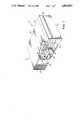
- FIG. 10is an enlarged cross-sectional view showing the mounting of one of the drive shafts used in the printing apparatus.
- FIGS. 1-10for showing a preferred embodiment of an improved electronic image printing apparatus 20 of the present invention.
- the printer 20relates generally to the electronic printer of the type described in the previously noted application. Accordingly, a detailed description of the printer 20 will not be given since many of the details thereof do not, per se, form part of the present invention. Such a detailed description is, however, incorporated herein and only those features considered necessary to explain and understand the present invention will be given.
- the electronic image printing apparatus 20is intended for use in generating and developing images on individual ones of a plurality of photosensitive film units 22 (FIG. 5A).
- These units 22are of the self-developing type, such as the kind manufactured by Polaroid Corporation.
- Other image recording mediaare contemplated for use. Whatever kinds are selected though, they should of course, be sensitive to exposure by a suitable source of energy used for recording purposes.
- each of the film units 22includes an image forming area 22a bordered by a frame having a rupturable pod of processing fluid, which pod is ruptured following processing by the electronic image printing apparatus 20 in a manner described more fully in the last noted application. Basically, such a film unit 22 is advanced to and between a pair of pressure applying spread rollers, to be described later.
- the spread rollerscause rupturing of the pod and spreading of the processing fluid between positive and image receiving elements (not shown) of the film unit 22 passing therebetween. This action initiates a known diffusion transfer process, whereby latent images on the image forming area 22a are developed.
- the film units 22, as is known,are held in a stacked array in a film cassette or box 24 (FIG. 5B).
- the film cassette 24is a known type used for housing the film units 22 of the above described kind. Such a film cassette 24 is described more fully in the last noted application or, for example, in commonly assigned U.S. Pat. No. 4,685,791. However, a brief description thereof is given here for purposes of better understanding this invention.
- the film cassette 24includes a wall 26 defining a light exposure aperture 28 which is arranged to be in registry with the image forming area 22a of successive ones of the film units 22.
- the film cassette 24includes a leading end wall assembly 30 having an exit slot 30a, an opposed rearward wall 32 and opposing sidewalls 34.
- a spring platen or pack spring(not shown) is arranged to provide a yieldable platform for the film units 22 so as to feed successive units to a focal plane defined by the cassette aperture 28. It should be noted that the film cassette 24 is arranged in the printer 20 so that the cassette aperture 28 faces downwardly.
- the wall 26is formed with an elongated recess or cutout which allows a picking mechanism, to be described later, to push successive exposed film units 22 through the exit slot 30a.
- the cassette 24is formed with datum projections 40 on the opposite sidewalls 34 which assist in properly positioning the cassette.
- the housing assembly 42includes a parallelpiped structure having top wall 42a, bottom wall 42b, opposing sidewalls 42c and respective front and back wall sections 42d and 42e.
- the film units 22are intended to be ejected from the film cassette 24 and through the front wall section or door 42d.
- the door 42dincludes an exit or discharge slot 44 which is sized and shaped to allow sequential ejection of a dark slide and processed film units 22 therethrough.
- the front door 42dis mounted pivotally to the housing assembly 42 so as to allow the front loading and removal of the film cassette 24.
- the front door 42dis latched in the closed position by a latch (not shown).
- a film cassette carriage 46(FIGS. 1-5) is mounted in the interior of the housing assembly 42 for reciprocating movement along a predetermined linear path between an image start printing position (see FIG. 9) and a film unit processing position (see FIG. 6).
- the pathis defined by a pair of spaced apart and generally parallel longitudinally extending guide rods 48, 50.
- a holding bracket 52which slidably supports the carriage for movement along the guide rod 48.
- a molded hollow bock 54which defines an internal bore 56 that is slidably supported on the guide rod 50.
- guide rod bracket 58protruding from this side of the cassette carriage 46 is guide rod bracket 58 (FIG. 5) defining a guide rod opening through which the guide rod 50 extends.
- a leaf spring 59(FIG. 5) upwardly biases the guide rod 50 against a vee-slot (not shown) in the guide rod bracket 58.
- Opposite end portions of the guide rod 50are supported respectively in a pair of mounting plates 60 which have snap-fit connections to corresponding structure on one of the sidewalls 42c (see FIG. 5). Opposite ends of the guide rods 48, 50 are also supported in suitable structure of the housing assembly 42.
- the cassette carriage 46has a ledge portion 62 defining an aperture 64 sized and shaped to be in registry with the aperture 28 and, therefore, the entire image area 22a of successive ones of the film units 22 that are sequentially presented to the aperture.
- the carriage 46has a pick slot (not shown) which allows picking of individual ones of exposed film units 22 from the cassette 24 when the latter is in the film processing position.
- an interlock device 66is arranged to snap-fit onto opposite sides of the carriage 46 and extend over the film cassette 24.
- the interlock device 66includes a pair of rearwardly extending interlock spring fingers 68 which prevent the cassette 24 from being loaded onto the carriage 46 in the wrong manner (i.e. aperture facing upwardly).
- a pair of spring members 70each having a downwardly extending tab which normally yieldably engages a datum surface 38 on each side of the cassette 46. Each tab is also engageable with a respective datum projection 40 as will be explained.
- This yieldable biasing of the spring members 70allows the carriage to overtravel relative to the cassette 24 for purposes of allowing overcentering of a coupling member which will be made clear subsequently.
- the inner surface of the sidewalls of the carriage 46provide frictional resistance to movement of the cassette 24 and since the biasing force of the springs 70 is greater than the frictional resistance, the springs 70 will position the cassette forwardly in the carriage.
- the film interlock deviceserves as a means for permitting overcentering of a coupling member to be described.
- FIGS. 2 and 3Provision is made for a compact and integral scanning mechanism or means 72. Reference is made to FIGS. 2 and 3 for showing the scanning mechanism 72.
- the scanning mechanism 72is operable for driving both the fast and slow scanning movements as is described better in the last noted application. A brief description of such a mechanism is given so as to better understand this invention.
- driving meanswhich includes an electric driving motor 74, a gear reduction arrangement 76 and a pair of slow scan and rapid return lead screws 78 and 80; respectively, each being selectively coupled to a coupling means or mechanism 82.
- the motor 74imparts rotational displacement to the counterrotating lead screws 78, 80. Both the lead screws 78, 80 extend generally parallel to the linear path of the carriage 46 and are journalled for rotation in the spaced apart mounting plates 60.
- the gear reduction arrangement 76includes gears 84 and 86 which are fixedly mounted on respective ones of the lead screws 78, 80 for rotation therewith.
- the gear 84meshingly engages the gear 86 and rotatably drives the latter at a greater speed.
- the lead screw 78drives the carriage 46 at a slower rate.
- the film cassette carriage 46can, therefore, return to the start printing position at a correspondingly faster speed.
- the printing apparatus 20can effectively expose and print more individual film units per unit time.
- the return lead screw 80has a pitch, for example 24 tpi, which is lower than the slow scan lead screw 78. This assists quicker return speed as well. As shown in FIG.
- a polished bearing ball 79housed in a recess therefor in one of the mounting plates 60.
- a polished end of the screw shaft 78contacts the ball under the urging of a spring clip 81. This cooperation facilitates the holding of precision of the operating components during slow scan.
- the coupling mechanism 82which includes a toggle nut assembly 88 and a pair of spaced apart actuator assemblies 90 (see FIGS. 5 & 6-9).
- the toggle nut assembly 88is selectively engageable with respective ones of the lead screws 78, 80 for facilitating the driving of the carriage 46 in opposite directions and at different speeds. Such selective engagement is in response to the actuator assemblies 90 selectively engaging the toggle nut assembly 88 as the latter moves.
- the toggle nut assembly 88(see FIG. 4). It includes essentially, the molded block 54, a toggle nut camming member or block 92 and a pair of bowed overcenter springs 94.
- the molded block 54has formed on spaced apart bottom portions thereof vee-slots 96. Each vee-slot 96 is formed to receive in a nested relationship thereto respective ones of pivot posts 98 extending from opposite sides of the toggle nut camming block 92.
- the toggle nut camming block 92can pivot relative to the molded block 54 and the lead screws 78, 80.
- the axes of the pivot postsintersect the axis of the lead screw 78. Accordingly, carriage movement deviation caused by lead screw runout is minimized greatly.
- the toggle nut camming block 92when engaged, converts the rotary motion of either of the lead screws 78, 80 to rectilinear carriage movement.
- the toggle nut camming block 92has dual threaded portions 100, 102 each one of which is threadedly engageable with respective ones of the lead screws 78, 80.
- the threaded portions 100, 102generally converge towards the rightmost end, as viewed in FIG. 4, of the camming block 92.
- the convergingfacilitates the toggle nut camming block 92 engaging only one of the lead screws and also faciitates mounting and adjusting of the block between relatively closely spaced lead screws. This enhances compactness of the toggle nut assembly 88.
- the bowed overcenter springs 94yieldably retain the toggle nut camming block 92 to the molded block 54. Because of the spring biasing, wear reduction of the threads does not have a serious affect on the movement of the carriage 46.
- the overcenter springs 94pull the carriage 46 downwardly and the camming block 92 upwardly. End portions of the overcenter springs 94 have hooked mounting sections. Upper end portions of the overcenter springs 94 fit through an opening formed in the molded block 54 and have their mounting sections cooperating with a transversely extended rod 104 in the molded block. The hooked mounting sections on opposite ends of the overcenter springs 94 are hooked onto a pair of protrusions on the camming block 92.
- One projection from the camming block 92is a camming post 106 (FIGS. 5 & 6-9).
- a reversing spring 112which form part of the actuator assemblies 90.
- Each reversing spring 112is secured to the sidewall 42c by a threaded member 114 (FIG. 5).
- Posts extending from the sidewall 42cengage opposite ends of each of the reversing springs 112, such as shown in the drawings.
- operative components on the sidewall 42 c, such as springs 112, threaded members 114 and backup cams 108are depicted for better understanding the operation of this invention while the sidewall 42c is not depicted.
- the biasing force of the reversing spring 112, following sufficient deflection, when releasedis such as to overcome the biasing force of the overcenter sprigs 94, to thereby shift or flip the camming block 92 to the other position (e.g. engaging the lead screw 80, see FIG. 7). It will be understood, that the reversing spring 112 cannot flip the camming block 92 until the camming post 106 slides off the backup cam 108 as will be later explained.
- the cassette carriage 46continues to be driven by the motor 74 until the switch 116 is closed by contact with a switch post 118 on the block 54. As a result, the slow scan lead screw 78 and the carriage 46 come to rest.
- the depicted position(FIG. 6) is referred to the film processing position.
- the carriage 46comes to rest at a location so that the camming post 106 remains engaged firmly by the backup cam 108 which provides a solid support, whereby loading and unloading of the cassette 24 from the carriage 46 will not cause undesired movement of the latter.
- the camming post 106cocks the reversing spring 112.
- the backup cams 108provide reaction members for bending of the reversing springs so that released stored energy of the latter can overcome the overcenter springs.
- the motor 74is again operated to drive the slow scan lead screw 78 so that the carriage overtravels or advances slightly rightwardly as viewed in the drawing (see FIG. 7) whereby the camming post 106 falls of the backup cam 108.
- the deflected reversing spring 112can release the stored energy to overcome the biasing of the overcenter springs 94 and as a result flip the camming block 92 to the position, whereat the threaded portion 102 engages the rapid return lead screw 80.
- the carriage 46will advance slowly towards the processing roller assembly (not shown).
- the cassette 24, if not already touching the processing roller assembly at that point in timewill do so and come to a stop while the carriage 46 overtravels rightwardly relative to the cassette.
- the spring members 70 which engage the projections 40deflect sufficiently to allow the carriage 46 to continue to advance enough so that the camming post 106 falls off the precipice of the backup cam 108.
- the camming post 106is driven downwardly by the reversing spring 112 whereby this movement results in the pivoting of the toggle nut camming block 92 downwardly.
- the threaded portion 102engages the lead screw 80 and the overcenter springs 94 which initially resist flipping will eventually assist in flipping the camming block 92 to this new position (FIG. 7).
- the carriage 46will then be driven rearwardly at a much faster rate. It being kept in mind that both the lead screws 78, 80 are rotating simultaneously.
- the camming post 106will eventually engage the other backup cam 108 (FIG. 8).
- the backup cam 108also facilitates cocking the bent arm 110 of the other reversing spring 112 until there is enough stored energy therein, so that when released it overcomes the combined biasing forces of the overcenter springs 94.
- the overcenter springs 94assist in flipping the camming block 92 so it reengages the slow scan lead screw 78.
- a bumping pad 120which engages the bottom of the camming block 92 near the end of its return stroke.
- the pad 120insures that the camming block 92 upon engagement therewith will pivot upwardly slightly and out of engagement with the rapid return lead screw 80.
- this disengagementoccurs when the camming post 106 is free of the backup cam 108.
- the reversing spring 112is thereby able to drive the camming block 92 upwardly, which upward movement is eventually assisted by the overcenter springs 94 themselves. Accordingly, the threaded portion 100 once again engages the lead screw 78.
- the switch post 118is situated so that it opens a switch 122 on the sidewall 42c (FIG. 5) when the camming block 92 reengages the slow scan lead screw 78.
- the motor 74then ceases operation and the carriage 46 comes to rest in the start printing position (FIG. 9). Because of carriage momentum, the switch post 118 is slightly placed beyond the switch 122 so that it reengages the switch to close the same when the motor 74 operates again to commence carriage movement in the opposite direction. In such a situation, the switch 122 when closed will signal the control circuit (not shown) to start the fast scanning and printing operations.
- fast scanningis considered movement of modulated light spots across the width of the film units 22. Both the slow and fast scanning movements provide for raster scan imaging on the film's image forming areas.
- FIGS. 2 and 3for showing the scanning mechanism 72 which performs the fast and slow scanning movements.
- the mirror driving mechanism 126includes a rotatable cam 128 directly connected to an output shaft of the driving motor 74.
- the scanning mirror assembly 124includes a generally rectangular scanning mirror 130 mounted for oscillation about a vertical axis defined by an upstanding support 132.
- the scanning mirror 130deflects the bundles of light being emitted from a light source of light emitting diodes (not shown) mounted on a board 131. Essentially, the scanning mirror 130 scans the film plane with a plurality of light spots emitted by the diodes.
- a cam follower 134is integral with the scanning mirror 130 and has one end thereof biased against a camming surface 136 of the cam 128 by a biasing spring (not shown).
- This springis connected to and between the cam follower 134 and a post (not shown) in the housing assembly 42 for yieldably urging the scanning mirror 130 to the starting scan position which is defined by the mirror contacting a stop (not shown) in the housing assembly 42.
- the cam follower 134will effect mirror oscillitation.
- the cam profileestablishes the position of the pixels on the film.
- an optical encoding mechanism 140Each time a signal is sensed by an optical sensor 142 of the encoding mechanism 140 a light source (not shown) as will be explained, is energized to emit light. Associated with the optical sensor 142 of the encoding mechanism 140 is an encoding wheel 144. The encoding wheel 144 is attached to an output shaft of the motor 74, as is generally described in the last noted application. The encoder wheel 144 has encoding marks (not shown) thereon which function with the optical sensor 142 to provide encoder tick clock pulses. In this embodiment, each encoder tick of the sensor 142 is transmitted to a data clock (not shown) in the control circuit (not shown).
- encoder responsive clock pulsesare transmitted to a microcomputer (not shown) in the control circuit.
- Image data received by the microcomputerfrom any well-known source, such as magnetic tape or disc is thereafter directed to circuitry (not shown) which modulates the intensity of the output of light emitting diodes of the light source.
- circuitrynot shown
- energization of the light emitting diodesis a function of the speed of motor output shaft since the encoder tick pulses are dependent upon the rotational displacement of the encoding wheel.
- the optical system 146 of his embodimentis essentially a preobjective scanning optical system, whereby the light emitted from the light emitting diodes scans along a predetermined flat path.
- a lens group 148which directs the beams from a stationary mirror 150 to the scanning mirror 130. From the scanning mirror 130 the beams are directed to a light converging lens group (not shown). From the light converging lens group the beams of light strike a pair of suitably placed reflecting mirrors (not shown) and go through the scanning slot (not shown) onto the flat film plane.
- the processing mechanism 154includes a motor (not shown), a gear train assembly 158 for driving a pair of film processing rollers 160 and 162 of a processing roller assembly and a film picking mechanism generally indicated by 164.
- the processing rollers 160 and 162are supported in the front door 42d of the housing assembly 42 and are spaced apart by a predetermined gap which gap facilitates formation of a desired processing fluid thickness used for processing the film units.
- a pair of springs(not shown) is provided, each one of which yieldably biases an end portion of the topmost processing roller 160.
- the processing rollers 160 and 162provide progressive pressure on the film units 22 as the latter travel therepast to initiate the diffusion transfer process.
- Film picking mechanism 164functions to pick a film unit 22 towards the processing rollers.
- the film picking mechanism 164functions like that described in the last noted application. Hence, a detailed description is not given herein. However, a brief description will be given.
- a projection on the sequencing gear 166is arranged to engage a tab 168 at the forward end of a pick slide 170. This engagement causes sliding movement of the pick slide 170 towards the forward position of the housing assembly 42. It will be appreciated that the pick slide 170 is suitably mounted and moves against the urging of a spring 172 which has its other end attached to the housing assembly 42. The spring 172 returns the pick slide 170 to its normal at rest position when the projection on the sequencing gear 166 no longer engages the tab 168.
- the pick slideupon engagement of the tab 168 by the sequencing gear 166, the pick slide is advanced for a limited stroke which is effective to cause a pick arm (not shown) connected to the pick slide 170 to engage a film unit 22.
- the pick armtravels through a slot (not shown) in the film carriage 46 and cutout (not shown) in the film cassette 24.
- Continued rotation of the sequencing gear 166will, of course, result in the pick arm advancing the film unit through the exit slot 30a, whereby the leading edge of the exited film unit is brought into engagement with the nip of the processing rollers 160, 162.
- the control circuitis effective to energize the motor 74. Accordingly, the gear reduction mechanism 76 is effective to simultaneously counterrotate both the lead screws 78, 80.
- the carriage 46in the start printing position the carriage 46 is in the position of FIG. 9 with the threaded portion 100 of the toggle nut camming block in engagement with the slow scan lead screw 78. Hence, the carriage 46 and film cassette 24 are driven towards the processing rollers 160, 162 at a slow rate.
- the switch post 118will engage the switch 116 and cause the motor 74 and thereby carriage movement to stop. Stoppage occurs while the camming post 106 is engaged with the backup cam 108 and causes deflection of the reversing spring 112.
- the backup cam 108provides support for the carriage and a reaction surface so that the arm 110 can be deflected. While the carriage is in this position, the film picking mechanism 164 and the film processing mechanism 154 are operated to eject the exposed film unit from the apparatus 20.
- the motor 74is again operated. Since the camming block 92 is still in engagement with the slow scan lead screw 78, the carriage 46 will advance rightwardly along with the camming block 92. The cassette 24 will be prevented from rightward movement because it engages the processing roller assembly (not shown). As the carriage 46 overtravels, the camming post 106 falls off the precipice of the backup cam 108. The stored energy of the deflected reversing spring 112 is now free to overcome the initial resistance of the overcenter springs 94 and drive the camming block 92 into engagement with the rapid return lead screw 80. The overcenter springs 94 will act to drive the camming block 92 into engagement with the return lead screw 80 after, of course, the camming block passes the overcenter position. Return of the carriage 46 to the start printing position commences upon such engagement.
- the carriage 46will eventually come to rest at the start position after the switch post 118 engages the switch 122. This causes the motor 74 to stop operation. Just prior to the switch 122 being contacted and the carriage coming to rest, the camming post 106 will fall off the backup cam 108 and the reversing spring 112 is sufficiently strong so that the latter can flip the camming block into engagement with the slow scan lead screw 78. Thus a cycle of carriage movement has been completed. Accordingly, the carriage can be moved as noted without requiring the motor to reverse direction of movement.
Landscapes
- Engineering & Computer Science (AREA)
- Multimedia (AREA)
- Signal Processing (AREA)
- Health & Medical Sciences (AREA)
- General Health & Medical Sciences (AREA)
- Toxicology (AREA)
- Character Spaces And Line Spaces In Printers (AREA)
- Transmission Devices (AREA)
- Printers Or Recording Devices Using Electromagnetic And Radiation Means (AREA)
- Optical Systems Of Projection Type Copiers (AREA)
- Facsimile Scanning Arrangements (AREA)
- Fax Reproducing Arrangements (AREA)
- Handling Of Cut Paper (AREA)
- Dot-Matrix Printers And Others (AREA)
- Sheets, Magazines, And Separation Thereof (AREA)
Abstract
Description
Claims (19)
Priority Applications (8)
| Application Number | Priority Date | Filing Date | Title |
|---|---|---|---|
| US07/188,265US4804982A (en) | 1988-04-29 | 1988-04-29 | Printer having reversible driving mechanism |
| US07/261,609US4868586A (en) | 1988-04-29 | 1988-10-24 | Reversible driving mechanism for electronic printer |
| CA000593945ACA1324215C (en) | 1988-04-29 | 1989-03-16 | Printer having reversible driving mechanism |
| DE89105675TDE68909294T2 (en) | 1988-04-29 | 1989-03-30 | Reversible drive mechanism printer. |
| DE198989105675TDE339287T1 (en) | 1988-04-29 | 1989-03-30 | PRINTER WITH REVERSIBLE DRIVE MECHANISM. |
| EP89105675AEP0339287B1 (en) | 1988-04-29 | 1989-03-30 | Printer having reversible driving mechanism |
| JP1106133AJPH0211350A (en) | 1988-04-29 | 1989-04-27 | Electronic picture printer |
| KR1019890005688AKR960001969B1 (en) | 1988-04-29 | 1989-04-28 | Printer having reversible driving mechanism |
Applications Claiming Priority (1)
| Application Number | Priority Date | Filing Date | Title |
|---|---|---|---|
| US07/188,265US4804982A (en) | 1988-04-29 | 1988-04-29 | Printer having reversible driving mechanism |
Related Child Applications (1)
| Application Number | Title | Priority Date | Filing Date |
|---|---|---|---|
| US07/261,609Continuation-In-PartUS4868586A (en) | 1988-04-29 | 1988-10-24 | Reversible driving mechanism for electronic printer |
Publications (1)
| Publication Number | Publication Date |
|---|---|
| US4804982Atrue US4804982A (en) | 1989-02-14 |
Family
ID=22692437
Family Applications (2)
| Application Number | Title | Priority Date | Filing Date |
|---|---|---|---|
| US07/188,265Expired - LifetimeUS4804982A (en) | 1988-04-29 | 1988-04-29 | Printer having reversible driving mechanism |
| US07/261,609Expired - LifetimeUS4868586A (en) | 1988-04-29 | 1988-10-24 | Reversible driving mechanism for electronic printer |
Family Applications After (1)
| Application Number | Title | Priority Date | Filing Date |
|---|---|---|---|
| US07/261,609Expired - LifetimeUS4868586A (en) | 1988-04-29 | 1988-10-24 | Reversible driving mechanism for electronic printer |
Country Status (6)
| Country | Link |
|---|---|
| US (2) | US4804982A (en) |
| EP (1) | EP0339287B1 (en) |
| JP (1) | JPH0211350A (en) |
| KR (1) | KR960001969B1 (en) |
| CA (1) | CA1324215C (en) |
| DE (2) | DE68909294T2 (en) |
Cited By (4)
| Publication number | Priority date | Publication date | Assignee | Title |
|---|---|---|---|---|
| US4985714A (en)* | 1990-01-22 | 1991-01-15 | Polaroid Corporation | Film dispenser with articulated catcher |
| EP0530027A3 (en)* | 1991-08-30 | 1993-04-14 | Nikon Corporation | An image digitizing system |
| US5923042A (en)* | 1994-10-11 | 1999-07-13 | International Business Machines Corporation | Method and apparatus for optically scanning transparent media |
| US5926289A (en)* | 1991-08-30 | 1999-07-20 | Nikon Corporation | Image digitizing system |
Families Citing this family (2)
| Publication number | Priority date | Publication date | Assignee | Title |
|---|---|---|---|---|
| US6069747A (en)* | 1997-01-30 | 2000-05-30 | Fuji Photo Film Co., Ltd. | Cam mechanism |
| US6417911B1 (en)* | 2000-01-31 | 2002-07-09 | Polaroid Corporation | Processing fluid spread system for an electronic photographic printer and camera and related method thereof |
Citations (9)
| Publication number | Priority date | Publication date | Assignee | Title |
|---|---|---|---|---|
| US1268048A (en)* | 1917-09-10 | 1918-05-28 | Orville P Norman | Mechanical movement. |
| US1421163A (en)* | 1920-10-08 | 1922-06-27 | Charles E Burrows | Reverse motion |
| US1918587A (en)* | 1930-12-03 | 1933-07-18 | T C Entwistle Company | Traverse-motion for winding machines and the like |
| US2158536A (en)* | 1936-07-23 | 1939-05-16 | Lefier Corp | Textile machine |
| US2467592A (en)* | 1943-07-22 | 1949-04-19 | Russell H Morgan | Driving mechanism for x-ray grids |
| US3927256A (en)* | 1973-12-29 | 1975-12-16 | Ricoh Kk | Variable-rate drive mechanism for a facsimile head or the like |
| US4159813A (en)* | 1977-10-19 | 1979-07-03 | Yale Engineering Inc. | Reciprocating traverse mechanism |
| US4727437A (en)* | 1986-01-09 | 1988-02-23 | Canon Kabushiki Kaisha | Recording apparatus with recording medium length sensors |
| US4754293A (en)* | 1986-04-04 | 1988-06-28 | Seiko Epson Corporation | Electrophotographic type image forming apparatus |
Family Cites Families (7)
| Publication number | Priority date | Publication date | Assignee | Title |
|---|---|---|---|---|
| JPS561245B2 (en)* | 1974-03-30 | 1981-01-12 | ||
| US4047192A (en)* | 1975-03-03 | 1977-09-06 | Polaroid Corporation | Photographic apparatus with sequencing system |
| JPS57173187A (en)* | 1981-05-18 | 1982-10-25 | Seiko Epson Corp | Head feeding mechanism for printer |
| JPS6044371A (en)* | 1983-08-20 | 1985-03-09 | Ricoh Co Ltd | How to drive a thermal head |
| US4584612A (en)* | 1984-02-21 | 1986-04-22 | Dainippon Screen Seizo Kabushiki Kaisha | Picture recording method |
| US4800400A (en)* | 1987-10-05 | 1989-01-24 | Polaroid Corporation | Electronic image printing apparatus |
| US4809020A (en)* | 1987-12-28 | 1989-02-28 | Polaroid Corporation | Control apparatus for electronic image printer |
- 1988
- 1988-04-29USUS07/188,265patent/US4804982A/ennot_activeExpired - Lifetime
- 1988-10-24USUS07/261,609patent/US4868586A/ennot_activeExpired - Lifetime
- 1989
- 1989-03-16CACA000593945Apatent/CA1324215C/ennot_activeExpired - Fee Related
- 1989-03-30DEDE89105675Tpatent/DE68909294T2/ennot_activeExpired - Fee Related
- 1989-03-30DEDE198989105675Tpatent/DE339287T1/enactivePending
- 1989-03-30EPEP89105675Apatent/EP0339287B1/ennot_activeExpired - Lifetime
- 1989-04-27JPJP1106133Apatent/JPH0211350A/enactivePending
- 1989-04-28KRKR1019890005688Apatent/KR960001969B1/ennot_activeExpired - Fee Related
Patent Citations (9)
| Publication number | Priority date | Publication date | Assignee | Title |
|---|---|---|---|---|
| US1268048A (en)* | 1917-09-10 | 1918-05-28 | Orville P Norman | Mechanical movement. |
| US1421163A (en)* | 1920-10-08 | 1922-06-27 | Charles E Burrows | Reverse motion |
| US1918587A (en)* | 1930-12-03 | 1933-07-18 | T C Entwistle Company | Traverse-motion for winding machines and the like |
| US2158536A (en)* | 1936-07-23 | 1939-05-16 | Lefier Corp | Textile machine |
| US2467592A (en)* | 1943-07-22 | 1949-04-19 | Russell H Morgan | Driving mechanism for x-ray grids |
| US3927256A (en)* | 1973-12-29 | 1975-12-16 | Ricoh Kk | Variable-rate drive mechanism for a facsimile head or the like |
| US4159813A (en)* | 1977-10-19 | 1979-07-03 | Yale Engineering Inc. | Reciprocating traverse mechanism |
| US4727437A (en)* | 1986-01-09 | 1988-02-23 | Canon Kabushiki Kaisha | Recording apparatus with recording medium length sensors |
| US4754293A (en)* | 1986-04-04 | 1988-06-28 | Seiko Epson Corporation | Electrophotographic type image forming apparatus |
Cited By (5)
| Publication number | Priority date | Publication date | Assignee | Title |
|---|---|---|---|---|
| US4985714A (en)* | 1990-01-22 | 1991-01-15 | Polaroid Corporation | Film dispenser with articulated catcher |
| EP0530027A3 (en)* | 1991-08-30 | 1993-04-14 | Nikon Corporation | An image digitizing system |
| US5926289A (en)* | 1991-08-30 | 1999-07-20 | Nikon Corporation | Image digitizing system |
| US6304344B1 (en) | 1991-08-30 | 2001-10-16 | Nikon Corporation | Image digitizing system |
| US5923042A (en)* | 1994-10-11 | 1999-07-13 | International Business Machines Corporation | Method and apparatus for optically scanning transparent media |
Also Published As
| Publication number | Publication date |
|---|---|
| US4868586A (en) | 1989-09-19 |
| DE68909294D1 (en) | 1993-10-28 |
| EP0339287A2 (en) | 1989-11-02 |
| DE68909294T2 (en) | 1994-01-13 |
| JPH0211350A (en) | 1990-01-16 |
| CA1324215C (en) | 1993-11-09 |
| DE339287T1 (en) | 1990-03-01 |
| EP0339287A3 (en) | 1991-04-24 |
| KR890016484A (en) | 1989-11-29 |
| KR960001969B1 (en) | 1996-02-08 |
| EP0339287B1 (en) | 1993-09-22 |
Similar Documents
| Publication | Publication Date | Title |
|---|---|---|
| CA1298126C (en) | Electronic image printing apparatus | |
| US5754314A (en) | Image input system and method for reading images from an original document | |
| EP0494674B1 (en) | Capping device for ink jet printer | |
| US5635973A (en) | Image reading and printing unit | |
| US4804982A (en) | Printer having reversible driving mechanism | |
| US3511152A (en) | Film advancing apparatus | |
| US5822637A (en) | Electronic camera and attachable printer | |
| US4809020A (en) | Control apparatus for electronic image printer | |
| US6565188B1 (en) | Cleaning device for inkjet recording head and inkjet recording device including the same | |
| US4952946A (en) | Scanning beam position detecting apparatus for use in electronic printer | |
| US4075639A (en) | Dual scanning focusing system | |
| US4651233A (en) | Tracking device for electronic still single-lens reflex camera | |
| JP2533224B2 (en) | Medium transport device | |
| US6046815A (en) | Retractable print medium tray for use in an optical printer | |
| US4286853A (en) | Microfiche camera having motor control system | |
| US6490414B2 (en) | Instant film unit advancing apparatus | |
| CA1299744C (en) | Aperture card printer | |
| US4912488A (en) | Camera with image input from linear array of electric-to-light transducers | |
| US4980777A (en) | Image recording apparatus | |
| JPH03263023A (en) | Reader/printer | |
| EP0722114A2 (en) | Printer with support shoe and exit media guide member | |
| JPH02249669A (en) | Recording apparatus | |
| JPH0247915B2 (en) | ||
| JP2002144635A (en) | Optical printer | |
| JP2002156699A (en) | Reciprocatingly moving mechanism |
Legal Events
| Date | Code | Title | Description |
|---|---|---|---|
| AS | Assignment | Owner name:POLARIOD CORPORATION, 549 TECHNOLOGY SQUARE, CAMBR Free format text:ASSIGNMENT OF ASSIGNORS INTEREST.;ASSIGNOR:NORRIS, PHILIP R.;REEL/FRAME:004879/0642 Effective date:19880429 Owner name:POLARIOD CORPORATION, A CORP. OF DE, MASSACHUSETTS Free format text:ASSIGNMENT OF ASSIGNORS INTEREST;ASSIGNOR:NORRIS, PHILIP R.;REEL/FRAME:004879/0642 Effective date:19880429 | |
| STCF | Information on status: patent grant | Free format text:PATENTED CASE | |
| FPAY | Fee payment | Year of fee payment:4 | |
| FPAY | Fee payment | Year of fee payment:8 | |
| FPAY | Fee payment | Year of fee payment:12 | |
| AS | Assignment | Owner name:MORGAN GUARANTY TRUST COMPANY OF NEW YORK, NEW YOR Free format text:SECURITY AGREEMENT;ASSIGNOR:POLAROID CORPORATION;REEL/FRAME:011658/0699 Effective date:20010321 | |
| AS | Assignment | Owner name:OEP IMAGINIG OPERATING CORPORATION, NEW YORK Free format text:ASSIGNMENT OF ASSIGNORS INTEREST;ASSIGNOR:POLAROID CORPORATION;REEL/FRAME:016427/0144 Effective date:20020731 Owner name:POLAROID CORPORATION, NEW YORK Free format text:CHANGE OF NAME;ASSIGNOR:OEP IMAGING OPERATING CORPORATION;REEL/FRAME:016470/0006 Effective date:20020801 Owner name:OEP IMAGINIG OPERATING CORPORATION,NEW YORK Free format text:ASSIGNMENT OF ASSIGNORS INTEREST;ASSIGNOR:POLAROID CORPORATION;REEL/FRAME:016427/0144 Effective date:20020731 Owner name:POLAROID CORPORATION,NEW YORK Free format text:CHANGE OF NAME;ASSIGNOR:OEP IMAGING OPERATING CORPORATION;REEL/FRAME:016470/0006 Effective date:20020801 | |
| AS | Assignment | Owner name:WILMINGTON TRUST COMPANY, AS COLLATERAL AGENT, DEL Free format text:ASSIGNMENT OF ASSIGNORS INTEREST;ASSIGNORS:POLAROLD HOLDING COMPANY;POLAROID CORPORATION;POLAROID ASIA PACIFIC LLC;AND OTHERS;REEL/FRAME:016602/0332 Effective date:20050428 Owner name:JPMORGAN CHASE BANK,N.A,AS ADMINISTRATIVE AGENT, W Free format text:SECURITY INTEREST;ASSIGNORS:POLAROID HOLDING COMPANY;POLAROID CORPORATION;POLAROID ASIA PACIFIC LLC;AND OTHERS;REEL/FRAME:016602/0603 Effective date:20050428 Owner name:WILMINGTON TRUST COMPANY, AS COLLATERAL AGENT,DELA Free format text:SECURITY AGREEMENT;ASSIGNORS:POLAROLD HOLDING COMPANY;POLAROID CORPORATION;POLAROID ASIA PACIFIC LLC;AND OTHERS;REEL/FRAME:016602/0332 Effective date:20050428 Owner name:JPMORGAN CHASE BANK,N.A,AS ADMINISTRATIVE AGENT,WI Free format text:SECURITY INTEREST;ASSIGNORS:POLAROID HOLDING COMPANY;POLAROID CORPORATION;POLAROID ASIA PACIFIC LLC;AND OTHERS;REEL/FRAME:016602/0603 Effective date:20050428 Owner name:WILMINGTON TRUST COMPANY, AS COLLATERAL AGENT, DEL Free format text:SECURITY AGREEMENT;ASSIGNORS:POLAROLD HOLDING COMPANY;POLAROID CORPORATION;POLAROID ASIA PACIFIC LLC;AND OTHERS;REEL/FRAME:016602/0332 Effective date:20050428 | |
| AS | Assignment | Owner name:POLAROID CORPORATION (F/K/A OEP IMAGING OPERATING Free format text:U.S. BANKRUPTCY COURT DISTRICT OF DELAWARE ORDER AUTHORIZING RELEASE OF ALL LIENS;ASSIGNOR:JPMORGAN CHASE BANK, N.A. (F/K/A MORGAN GUARANTY TRUST COMPANY OF NEW YORK);REEL/FRAME:016621/0377 Effective date:20020418 | |
| AS | Assignment | Owner name:OEP IMAGING OPERATING CORPORATION,NEW YORK Free format text:ASSIGNMENT OF ASSIGNORS INTEREST;ASSIGNOR:POLAROID CORPORATION;REEL/FRAME:018584/0600 Effective date:20020731 Owner name:OEP IMAGING OPERATING CORPORATION, NEW YORK Free format text:ASSIGNMENT OF ASSIGNORS INTEREST;ASSIGNOR:POLAROID CORPORATION;REEL/FRAME:018584/0600 Effective date:20020731 | |
| AS | Assignment | Owner name:POLAROID CORPORATION (FMR OEP IMAGING OPERATING CO Free format text:SUPPLEMENTAL ASSIGNMENT OF PATENTS;ASSIGNOR:PRIMARY PDC, INC. (FMR POLAROID CORPORATION);REEL/FRAME:019077/0001 Effective date:20070122 | |
| AS | Assignment | Owner name:POLAROID HOLDING COMPANY, MASSACHUSETTS Free format text:RELEASE OF SECURITY INTEREST IN PATENTS;ASSIGNOR:WILMINGTON TRUST COMPANY;REEL/FRAME:019699/0512 Effective date:20070425 Owner name:POLAROID CORPORATION, MASSACHUSETTS Free format text:RELEASE OF SECURITY INTEREST IN PATENTS;ASSIGNOR:WILMINGTON TRUST COMPANY;REEL/FRAME:019699/0512 Effective date:20070425 Owner name:POLAROID CAPITAL LLC, MASSACHUSETTS Free format text:RELEASE OF SECURITY INTEREST IN PATENTS;ASSIGNOR:WILMINGTON TRUST COMPANY;REEL/FRAME:019699/0512 Effective date:20070425 Owner name:POLAROID ASIA PACIFIC LLC, MASSACHUSETTS Free format text:RELEASE OF SECURITY INTEREST IN PATENTS;ASSIGNOR:WILMINGTON TRUST COMPANY;REEL/FRAME:019699/0512 Effective date:20070425 Owner name:POLAROID EYEWEAR LLC, MASSACHUSETTS Free format text:RELEASE OF SECURITY INTEREST IN PATENTS;ASSIGNOR:WILMINGTON TRUST COMPANY;REEL/FRAME:019699/0512 Effective date:20070425 Owner name:POLOROID INTERNATIONAL HOLDING LLC, MASSACHUSETTS Free format text:RELEASE OF SECURITY INTEREST IN PATENTS;ASSIGNOR:WILMINGTON TRUST COMPANY;REEL/FRAME:019699/0512 Effective date:20070425 Owner name:POLAROID INVESTMENT LLC, MASSACHUSETTS Free format text:RELEASE OF SECURITY INTEREST IN PATENTS;ASSIGNOR:WILMINGTON TRUST COMPANY;REEL/FRAME:019699/0512 Effective date:20070425 Owner name:POLAROID LATIN AMERICA I CORPORATION, MASSACHUSETT Free format text:RELEASE OF SECURITY INTEREST IN PATENTS;ASSIGNOR:WILMINGTON TRUST COMPANY;REEL/FRAME:019699/0512 Effective date:20070425 Owner name:POLAROID NEW BEDFORD REAL ESTATE LLC, MASSACHUSETT Free format text:RELEASE OF SECURITY INTEREST IN PATENTS;ASSIGNOR:WILMINGTON TRUST COMPANY;REEL/FRAME:019699/0512 Effective date:20070425 Owner name:POLAROID NORWOOD REAL ESTATE LLC, MASSACHUSETTS Free format text:RELEASE OF SECURITY INTEREST IN PATENTS;ASSIGNOR:WILMINGTON TRUST COMPANY;REEL/FRAME:019699/0512 Effective date:20070425 Owner name:POLAROID WALTHAM REAL ESTATE LLC, MASSACHUSETTS Free format text:RELEASE OF SECURITY INTEREST IN PATENTS;ASSIGNOR:WILMINGTON TRUST COMPANY;REEL/FRAME:019699/0512 Effective date:20070425 Owner name:PETTERS CONSUMER BRANDS, LLC, MASSACHUSETTS Free format text:RELEASE OF SECURITY INTEREST IN PATENTS;ASSIGNOR:WILMINGTON TRUST COMPANY;REEL/FRAME:019699/0512 Effective date:20070425 Owner name:PETTERS CONSUMER BRANDS INTERNATIONAL, LLC, MASSAC Free format text:RELEASE OF SECURITY INTEREST IN PATENTS;ASSIGNOR:WILMINGTON TRUST COMPANY;REEL/FRAME:019699/0512 Effective date:20070425 Owner name:ZINK INCORPORATED, MASSACHUSETTS Free format text:RELEASE OF SECURITY INTEREST IN PATENTS;ASSIGNOR:WILMINGTON TRUST COMPANY;REEL/FRAME:019699/0512 Effective date:20070425 Owner name:POLAROID HOLDING COMPANY,MASSACHUSETTS Free format text:RELEASE OF SECURITY INTEREST IN PATENTS;ASSIGNOR:WILMINGTON TRUST COMPANY;REEL/FRAME:019699/0512 Effective date:20070425 Owner name:POLAROID CORPORATION,MASSACHUSETTS Free format text:RELEASE OF SECURITY INTEREST IN PATENTS;ASSIGNOR:WILMINGTON TRUST COMPANY;REEL/FRAME:019699/0512 Effective date:20070425 Owner name:POLAROID CAPITAL LLC,MASSACHUSETTS Free format text:RELEASE OF SECURITY INTEREST IN PATENTS;ASSIGNOR:WILMINGTON TRUST COMPANY;REEL/FRAME:019699/0512 Effective date:20070425 Owner name:POLAROID ASIA PACIFIC LLC,MASSACHUSETTS Free format text:RELEASE OF SECURITY INTEREST IN PATENTS;ASSIGNOR:WILMINGTON TRUST COMPANY;REEL/FRAME:019699/0512 Effective date:20070425 Owner name:POLAROID EYEWEAR LLC,MASSACHUSETTS Free format text:RELEASE OF SECURITY INTEREST IN PATENTS;ASSIGNOR:WILMINGTON TRUST COMPANY;REEL/FRAME:019699/0512 Effective date:20070425 Owner name:POLOROID INTERNATIONAL HOLDING LLC,MASSACHUSETTS Free format text:RELEASE OF SECURITY INTEREST IN PATENTS;ASSIGNOR:WILMINGTON TRUST COMPANY;REEL/FRAME:019699/0512 Effective date:20070425 Owner name:POLAROID INVESTMENT LLC,MASSACHUSETTS Free format text:RELEASE OF SECURITY INTEREST IN PATENTS;ASSIGNOR:WILMINGTON TRUST COMPANY;REEL/FRAME:019699/0512 Effective date:20070425 Owner name:POLAROID LATIN AMERICA I CORPORATION,MASSACHUSETTS Free format text:RELEASE OF SECURITY INTEREST IN PATENTS;ASSIGNOR:WILMINGTON TRUST COMPANY;REEL/FRAME:019699/0512 Effective date:20070425 Owner name:POLAROID NEW BEDFORD REAL ESTATE LLC,MASSACHUSETTS Free format text:RELEASE OF SECURITY INTEREST IN PATENTS;ASSIGNOR:WILMINGTON TRUST COMPANY;REEL/FRAME:019699/0512 Effective date:20070425 Owner name:POLAROID NORWOOD REAL ESTATE LLC,MASSACHUSETTS Free format text:RELEASE OF SECURITY INTEREST IN PATENTS;ASSIGNOR:WILMINGTON TRUST COMPANY;REEL/FRAME:019699/0512 Effective date:20070425 Owner name:POLAROID WALTHAM REAL ESTATE LLC,MASSACHUSETTS Free format text:RELEASE OF SECURITY INTEREST IN PATENTS;ASSIGNOR:WILMINGTON TRUST COMPANY;REEL/FRAME:019699/0512 Effective date:20070425 Owner name:PETTERS CONSUMER BRANDS, LLC,MASSACHUSETTS Free format text:RELEASE OF SECURITY INTEREST IN PATENTS;ASSIGNOR:WILMINGTON TRUST COMPANY;REEL/FRAME:019699/0512 Effective date:20070425 Owner name:PETTERS CONSUMER BRANDS INTERNATIONAL, LLC,MASSACH Free format text:RELEASE OF SECURITY INTEREST IN PATENTS;ASSIGNOR:WILMINGTON TRUST COMPANY;REEL/FRAME:019699/0512 Effective date:20070425 Owner name:ZINK INCORPORATED,MASSACHUSETTS Free format text:RELEASE OF SECURITY INTEREST IN PATENTS;ASSIGNOR:WILMINGTON TRUST COMPANY;REEL/FRAME:019699/0512 Effective date:20070425 | |
| AS | Assignment | Owner name:POLAROID HOLDING COMPANY, MASSACHUSETTS Free format text:RELEASE OF SECURITY INTEREST IN PATENTS;ASSIGNOR:JPMORGAN CHASE BANK, N.A.;REEL/FRAME:020733/0001 Effective date:20080225 Owner name:POLAROID INTERNATIONAL HOLDING LLC, MASSACHUSETTS Free format text:RELEASE OF SECURITY INTEREST IN PATENTS;ASSIGNOR:JPMORGAN CHASE BANK, N.A.;REEL/FRAME:020733/0001 Effective date:20080225 Owner name:POLAROID INVESTMENT LLC, MASSACHUSETTS Free format text:RELEASE OF SECURITY INTEREST IN PATENTS;ASSIGNOR:JPMORGAN CHASE BANK, N.A.;REEL/FRAME:020733/0001 Effective date:20080225 Owner name:POLAROID LATIN AMERICA I CORPORATION, MASSACHUSETT Free format text:RELEASE OF SECURITY INTEREST IN PATENTS;ASSIGNOR:JPMORGAN CHASE BANK, N.A.;REEL/FRAME:020733/0001 Effective date:20080225 Owner name:POLAROID NEW BEDFORD REAL ESTATE LLC, MASSACHUSETT Free format text:RELEASE OF SECURITY INTEREST IN PATENTS;ASSIGNOR:JPMORGAN CHASE BANK, N.A.;REEL/FRAME:020733/0001 Effective date:20080225 Owner name:POLAROID NORWOOD REAL ESTATE LLC, MASSACHUSETTS Free format text:RELEASE OF SECURITY INTEREST IN PATENTS;ASSIGNOR:JPMORGAN CHASE BANK, N.A.;REEL/FRAME:020733/0001 Effective date:20080225 Owner name:POLAROID WALTHAM REAL ESTATE LLC, MASSACHUSETTS Free format text:RELEASE OF SECURITY INTEREST IN PATENTS;ASSIGNOR:JPMORGAN CHASE BANK, N.A.;REEL/FRAME:020733/0001 Effective date:20080225 Owner name:POLAROID CONSUMER ELECTRONICS, LLC, (FORMERLY KNOW Free format text:RELEASE OF SECURITY INTEREST IN PATENTS;ASSIGNOR:JPMORGAN CHASE BANK, N.A.;REEL/FRAME:020733/0001 Effective date:20080225 Owner name:POLAROID CONSUMER ELECTRONICS INTERNATIONAL, LLC, Free format text:RELEASE OF SECURITY INTEREST IN PATENTS;ASSIGNOR:JPMORGAN CHASE BANK, N.A.;REEL/FRAME:020733/0001 Effective date:20080225 Owner name:ZINK INCORPORATED, MASSACHUSETTS Free format text:RELEASE OF SECURITY INTEREST IN PATENTS;ASSIGNOR:JPMORGAN CHASE BANK, N.A.;REEL/FRAME:020733/0001 Effective date:20080225 Owner name:POLAROID CORPORATION, MASSACHUSETTS Free format text:RELEASE OF SECURITY INTEREST IN PATENTS;ASSIGNOR:JPMORGAN CHASE BANK, N.A.;REEL/FRAME:020733/0001 Effective date:20080225 Owner name:POLAROID ASIA PACIFIC LLC, MASSACHUSETTS Free format text:RELEASE OF SECURITY INTEREST IN PATENTS;ASSIGNOR:JPMORGAN CHASE BANK, N.A.;REEL/FRAME:020733/0001 Effective date:20080225 Owner name:POLAROID CAPITAL LLC, MASSACHUSETTS Free format text:RELEASE OF SECURITY INTEREST IN PATENTS;ASSIGNOR:JPMORGAN CHASE BANK, N.A.;REEL/FRAME:020733/0001 Effective date:20080225 Owner name:PLLAROID EYEWEAR I LLC, MASSACHUSETTS Free format text:RELEASE OF SECURITY INTEREST IN PATENTS;ASSIGNOR:JPMORGAN CHASE BANK, N.A.;REEL/FRAME:020733/0001 Effective date:20080225 Owner name:POLAROID HOLDING COMPANY,MASSACHUSETTS Free format text:RELEASE OF SECURITY INTEREST IN PATENTS;ASSIGNOR:JPMORGAN CHASE BANK, N.A.;REEL/FRAME:020733/0001 Effective date:20080225 Owner name:POLAROID INTERNATIONAL HOLDING LLC,MASSACHUSETTS Free format text:RELEASE OF SECURITY INTEREST IN PATENTS;ASSIGNOR:JPMORGAN CHASE BANK, N.A.;REEL/FRAME:020733/0001 Effective date:20080225 Owner name:POLAROID INVESTMENT LLC,MASSACHUSETTS Free format text:RELEASE OF SECURITY INTEREST IN PATENTS;ASSIGNOR:JPMORGAN CHASE BANK, N.A.;REEL/FRAME:020733/0001 Effective date:20080225 Owner name:POLAROID LATIN AMERICA I CORPORATION,MASSACHUSETTS Free format text:RELEASE OF SECURITY INTEREST IN PATENTS;ASSIGNOR:JPMORGAN CHASE BANK, N.A.;REEL/FRAME:020733/0001 Effective date:20080225 Owner name:POLAROID NEW BEDFORD REAL ESTATE LLC,MASSACHUSETTS Free format text:RELEASE OF SECURITY INTEREST IN PATENTS;ASSIGNOR:JPMORGAN CHASE BANK, N.A.;REEL/FRAME:020733/0001 Effective date:20080225 Owner name:POLAROID NORWOOD REAL ESTATE LLC,MASSACHUSETTS Free format text:RELEASE OF SECURITY INTEREST IN PATENTS;ASSIGNOR:JPMORGAN CHASE BANK, N.A.;REEL/FRAME:020733/0001 Effective date:20080225 Owner name:POLAROID WALTHAM REAL ESTATE LLC,MASSACHUSETTS Free format text:RELEASE OF SECURITY INTEREST IN PATENTS;ASSIGNOR:JPMORGAN CHASE BANK, N.A.;REEL/FRAME:020733/0001 Effective date:20080225 Owner name:ZINK INCORPORATED,MASSACHUSETTS Free format text:RELEASE OF SECURITY INTEREST IN PATENTS;ASSIGNOR:JPMORGAN CHASE BANK, N.A.;REEL/FRAME:020733/0001 Effective date:20080225 Owner name:POLAROID CORPORATION,MASSACHUSETTS Free format text:RELEASE OF SECURITY INTEREST IN PATENTS;ASSIGNOR:JPMORGAN CHASE BANK, N.A.;REEL/FRAME:020733/0001 Effective date:20080225 Owner name:POLAROID ASIA PACIFIC LLC,MASSACHUSETTS Free format text:RELEASE OF SECURITY INTEREST IN PATENTS;ASSIGNOR:JPMORGAN CHASE BANK, N.A.;REEL/FRAME:020733/0001 Effective date:20080225 Owner name:POLAROID CAPITAL LLC,MASSACHUSETTS Free format text:RELEASE OF SECURITY INTEREST IN PATENTS;ASSIGNOR:JPMORGAN CHASE BANK, N.A.;REEL/FRAME:020733/0001 Effective date:20080225 Owner name:PLLAROID EYEWEAR I LLC,MASSACHUSETTS Free format text:RELEASE OF SECURITY INTEREST IN PATENTS;ASSIGNOR:JPMORGAN CHASE BANK, N.A.;REEL/FRAME:020733/0001 Effective date:20080225 | |
| AS | Assignment | Owner name:SENSHIN CAPITAL, LLC, DELAWARE Free format text:ASSIGNMENT OF ASSIGNORS INTEREST;ASSIGNOR:POLAROID CORPORATION;REEL/FRAME:021040/0001 Effective date:20080415 Owner name:SENSHIN CAPITAL, LLC,DELAWARE Free format text:ASSIGNMENT OF ASSIGNORS INTEREST;ASSIGNOR:POLAROID CORPORATION;REEL/FRAME:021040/0001 Effective date:20080415 |