US4804368A - Battery operated miniature syringe infusion pump and improved halfnut therefor - Google Patents
Battery operated miniature syringe infusion pump and improved halfnut thereforDownload PDFInfo
- Publication number
- US4804368A US4804368AUS07/088,806US8880687AUS4804368AUS 4804368 AUS4804368 AUS 4804368AUS 8880687 AUS8880687 AUS 8880687AUS 4804368 AUS4804368 AUS 4804368A
- Authority
- US
- United States
- Prior art keywords
- halfnut
- leadscrew
- drive
- block
- syringe
- Prior art date
- Legal status (The legal status is an assumption and is not a legal conclusion. Google has not performed a legal analysis and makes no representation as to the accuracy of the status listed.)
- Expired - Lifetime
Links
- 238000001802infusionMethods0.000titleclaimsabstractdescription16
- 230000007246mechanismEffects0.000claimsabstractdescription9
- 238000000926separation methodMethods0.000claimsdescription9
- 230000009471actionEffects0.000claimsdescription3
- 238000013459approachMethods0.000claims1
- 239000003814drugSubstances0.000description5
- 230000008901benefitEffects0.000description3
- 238000006243chemical reactionMethods0.000description3
- 230000008878couplingEffects0.000description3
- 238000010168coupling processMethods0.000description3
- 238000005859coupling reactionMethods0.000description3
- 238000010586diagramMethods0.000description3
- 238000013461designMethods0.000description2
- 229940079593drugDrugs0.000description2
- 230000000694effectsEffects0.000description2
- 238000001990intravenous administrationMethods0.000description2
- 239000000463materialSubstances0.000description2
- 230000009467reductionEffects0.000description2
- 230000000153supplemental effectEffects0.000description2
- 229910000975Carbon steelInorganic materials0.000description1
- 208000003870Drug OverdoseDiseases0.000description1
- 206010033296OverdosesDiseases0.000description1
- 239000003242anti bacterial agentSubstances0.000description1
- 229940088710antibiotic agentDrugs0.000description1
- 230000000712assemblyEffects0.000description1
- 238000000429assemblyMethods0.000description1
- 239000010962carbon steelSubstances0.000description1
- 238000010276constructionMethods0.000description1
- 238000012377drug deliveryMethods0.000description1
- 231100000725drug overdoseToxicity0.000description1
- 230000001771impaired effectEffects0.000description1
- 230000006872improvementEffects0.000description1
- 238000010348incorporationMethods0.000description1
- 230000003993interactionEffects0.000description1
- 238000000034methodMethods0.000description1
- 230000000474nursing effectEffects0.000description1
- 230000002093peripheral effectEffects0.000description1
- 238000007747platingMethods0.000description1
- 229940124597therapeutic agentDrugs0.000description1
- 229940126585therapeutic drugDrugs0.000description1
- 238000013519translationMethods0.000description1
- 230000000007visual effectEffects0.000description1
Images


Classifications
- A—HUMAN NECESSITIES
- A61—MEDICAL OR VETERINARY SCIENCE; HYGIENE
- A61M—DEVICES FOR INTRODUCING MEDIA INTO, OR ONTO, THE BODY; DEVICES FOR TRANSDUCING BODY MEDIA OR FOR TAKING MEDIA FROM THE BODY; DEVICES FOR PRODUCING OR ENDING SLEEP OR STUPOR
- A61M5/00—Devices for bringing media into the body in a subcutaneous, intra-vascular or intramuscular way; Accessories therefor, e.g. filling or cleaning devices, arm-rests
- A61M5/14—Infusion devices, e.g. infusing by gravity; Blood infusion; Accessories therefor
- A61M5/142—Pressure infusion, e.g. using pumps
- A61M5/145—Pressure infusion, e.g. using pumps using pressurised reservoirs, e.g. pressurised by means of pistons
- A61M5/1452—Pressure infusion, e.g. using pumps using pressurised reservoirs, e.g. pressurised by means of pistons pressurised by means of pistons
- A61M5/1456—Pressure infusion, e.g. using pumps using pressurised reservoirs, e.g. pressurised by means of pistons pressurised by means of pistons with a replaceable reservoir comprising a piston rod to be moved into the reservoir, e.g. the piston rod is part of the removable reservoir
- A—HUMAN NECESSITIES
- A61—MEDICAL OR VETERINARY SCIENCE; HYGIENE
- A61M—DEVICES FOR INTRODUCING MEDIA INTO, OR ONTO, THE BODY; DEVICES FOR TRANSDUCING BODY MEDIA OR FOR TAKING MEDIA FROM THE BODY; DEVICES FOR PRODUCING OR ENDING SLEEP OR STUPOR
- A61M5/00—Devices for bringing media into the body in a subcutaneous, intra-vascular or intramuscular way; Accessories therefor, e.g. filling or cleaning devices, arm-rests
- A61M5/14—Infusion devices, e.g. infusing by gravity; Blood infusion; Accessories therefor
- A61M5/142—Pressure infusion, e.g. using pumps
- A61M5/145—Pressure infusion, e.g. using pumps using pressurised reservoirs, e.g. pressurised by means of pistons
- A61M5/1452—Pressure infusion, e.g. using pumps using pressurised reservoirs, e.g. pressurised by means of pistons pressurised by means of pistons
- A61M2005/14573—Pressure infusion, e.g. using pumps using pressurised reservoirs, e.g. pressurised by means of pistons pressurised by means of pistons with a replaceable reservoir for quick connection/disconnection with a driving system
- Y—GENERAL TAGGING OF NEW TECHNOLOGICAL DEVELOPMENTS; GENERAL TAGGING OF CROSS-SECTIONAL TECHNOLOGIES SPANNING OVER SEVERAL SECTIONS OF THE IPC; TECHNICAL SUBJECTS COVERED BY FORMER USPC CROSS-REFERENCE ART COLLECTIONS [XRACs] AND DIGESTS
- Y10—TECHNICAL SUBJECTS COVERED BY FORMER USPC
- Y10S—TECHNICAL SUBJECTS COVERED BY FORMER USPC CROSS-REFERENCE ART COLLECTIONS [XRACs] AND DIGESTS
- Y10S128/00—Surgery
- Y10S128/01—Motorized syringe
Definitions
- This inventionrelates to an improved battery operated miniature syringe infusion pump of the type disclosed in commonly assigned U.S. Pat. No. 4,544,369 with an improved halfnut/leadscrew assembly therefor, wherein the halfnut is resiliently held against the lead screw.
- syringe infusion pump drivesare motor driven leadscrew assemblies.
- a halfnut driving nutis typically used for easy resetting of the drive when an emptied syringe is to be replaced with a filled syringe.
- the driveFor accurate drug delivery, it is necessary that the drive be fully engaged without slipping under load. Nonetheless, for ease of use by nursing personnel, the drive must be easily decoupled for resetting without excessive force or unusual skill.
- Halfnut/leadscrew drive mechanisms for syringe infusion pumpshave therefore been used to translate rotary motion to linear motion yet provide convenient drive disengagement if required. Because of their ability to be disengaged by the operator, their design is not necessarily straightforward. They need to be easily disengaged, yet must remain fully engaged under all expected driving conditions.
- a guided halfnut of the type disclosed in U.S. Pat. No. 4,544,369requires a relatively large supplemental engagement force between the halfnut and leadscrew to assure engagement under all conditions.
- This forceis typically supplied by a spring.
- This spring forcemust be overcome by the operator during disengagement. Further, the necessary spring force increases with increasing drive loads. Stated another way, the drive load will bring about forces which tend to separate the leadscrew and halfnut, and these forces must be counteracted by an external, supplemental force.
- a jamming halfnuthas also been disclosed in the prior art and can be designed such that the drive load causes forces which tend to engage the halfnut with the leadscrew.
- the geometry of the systemis made so that the halfnut/leadscrew reaction and the halfnut/pusher block reaction are equal but opposite Therefore, the separation component of the former is countered by the restoring component of the latter and engagement is maintained.
- the present inventionrecognized that placing the contact points between the pusher block and halfnut near the midpoint of the leadscrew greatly reduces the force mechanisms that attempt to separate the halfnut from the leadscrew. Further, the halfnut is neither guided nor pivoted against the leadscrew as in the prior art, but is allowed to float under the influence of the drive load, spring force, friction forces between the halfnut and leadscrew, and frictional forces between the halfnut and pusher block. A balance of forces was made to exist by properly choosing the contact points among the halfnut, leadscrew, and pusher block, and by allowing the halfnut to float so that leadscrew rotation will not result in net frictional separation forces. This balance of forces resulted in an unconditionally stable mechanical arrangement in which separation can never result from applied drive loads(within material performance characteristics). Nonetheless, drive decoupling could still be accomplished by simple translation of the halfnut perpendicular to the leadscrew.
- the infusion pump of this inventionwhereby the foregoing objects are attained will hold and empty a syringe.
- Its syringe barrelis secured in a snap-in holder and the syringe plunger is moved by a pusher having a halfnut forced against the leadscrew.
- the pusheris advanced to the syringe plunger during set-up by squeezing a finger tab and sliding the pusher forward. This simultaneously decouples the pusher from the internal drive and opens the antisiphon catch to allow quick and easy set-up.
- a switchis moved to the "on" position.
- the pusheris moved by the engagement of a nut on a threaded leadscrew.
- the leadscrewis rotated, through appropriate gearing, by a motor.
- a force sensing systemis included as part of the syringe holder and is used to detect end of syringe and occlusion. Visual indicators and audio alarms for infusion and warning and to sense condition of the batteries are provided
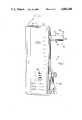
- FIG. 1is a front elevational view of a battery operated syringe infusion pump incorporating the teachings of this invention
- FIG. 2is a similar front elevational view with the front cover removed;
- FIG. 3is an enlarged side elevational view of the pusher block assembly with certain parts broken away, removed and sectioned;
- FIG. 4is an enlarged fragmentary view of the pusher block assembly shown associated with the leadscrew;
- FIG. 5is an end view of motor gear drive for the leadscrew
- FIG. 6is a vector force balance diagram of the invention showing diagramatically the interaction among the pusher block, halfnut and leadscrew.
- a small, lightweight battery operated syringe infusion pump 10 of this inventionis adapted to be hung or suspended from an IV pole or similar conveniently located support by means of attachment loop 12 pivotal between a retracted position and an extended position as shown in FIG. 1.
- a front cover 14 and a rear cover 16advantageously houses the internal componentry and defines compartment 18 that conveniently receives the batteries 20 for energizing the fixed and single or multiple speed motor 22.
- the drive of motor 22is coupled with gear network 24 which in turn drives the leadscrew 26 as shown in FIGS. 4 and 5.
- a pusher block assembly 28is provided with a floating drive halfnut 30 which advantageously engages with the leadscrew 26.
- the assemblyalso selectively engages with the rear end of the syringe plunger for expelling and discharge of the syringe contents.
- the pusher block assemblyincludes a block 32 that has a bottom end 34 provided with a pair of channels 36, 38 that receive guide rods 40, 42 which cooperate in causing the pusher block assembly 28 to move forwardly upon turning of the leadscrew 26 as a result of the meshing therewith by the floating drive halfnut 30.
- a lever 44slides and is captured in the block 32.
- the spring 46is secured at one end to the lower surface of leg 58 and fits around the head 57 of the shaft or actuator 59.
- spring 46is fixed to the inner peripheral flange 61 of lever 44. It is thus seen that by lifting lever 44 upwardly the shaft 59 will move upwardly in bore or opening 41 in block bottom end 34; and, consequently, the halfnut 30 will be moved upwardly into the bottom end 34 at the bottom of the pusher block 32.
- Spring 48which is contained in housing block bottom end 34 continuously biases the floating halfnut 30 against the leadscrew 26.
- the upper spring 46which surrounds the head 57 of the halfnut shaft or actuator 59 provides the force to keep the lever 44 and antisiphon catch 50 engaged with flange 52 of plunger 54 of syringe 56 shown in FIG. 2. In this manner, escape of plunger 54 is prevented which otherwise could result in a siphoning action.
- Spring 46is biased between leg 58 and flange 61. Flange 61 also acts to engage head 57 to cause disengagement of the halfnut 30 and leadscrew 26.
- FIG. 6shows a simplified, two-dimensional force balance diagram which describes the floating halfnut of the invention. While the disclosed halfnut has three dimensional loading characteristics, these characteristics are not essential for a basic understanding of the invention.
- F Arefers to the axial force exerted by the pusher block 32 on halfnut 30 as a result of the driven load.
- F srefers to the force exerted by spring 48 on halfnut 32.
- F Pfrefers to the frictional force existing between the pusher block 32 and the halfnut 30.
- F Lfrefers to the frictional force between the halfnut 30 and the leadscrew 26.
- F Lrefers to the force in the axial direction exerted by the leadscrew 26 on the halfnut 30, and F R represents the total reaction attempting to separate the halfnut 30 from the leadscrew 26.
- a successful embodimenthas a spring force of approximately 2 lbs.
- the current embodimenthas been estimated by the theoretical analysis to provide stable engagement regardless of the axial force F A and, further, requires no spring force F S to assure this engagement. That is, F Pf plus F Lf is estimated to be larger than F R for all F A 's.
- the floating halfnut of the present inventionwill develop forces due to the system friction and drive load which are greater than the separation forces that exist.
- the engagement forcesare due to friction between the halfnut and leadscrew, and between the halfnut and pusher block.
- a floating halfnutis so constructed that essentially no externally applied load is required to maintain engagement. This balance of forces is accomplished by properly choosing the supporting contact points among the halfnut, leadscrew, and pusher block, and by allowing the halfnut to float so that the leadscrew rotation does not add frictional separation forces.
- the position of the pusher block 32can be advantageously and quickly readjusted by disengaging the halfnut 30 with a minimum of manual effort because the spring force of spring 48 is at a minimum.
- the pusher block lever 44is grasped and pulled.
- Squeezing lever 44 towards the upper laterally extending leg 58 of block 32will permit the syringe plunger flange 52 to be immediately released or permit the flange of a fresh syringe 56 to be engaged by the pusher block 28.
- the pusher block assembly 28may then be freely moved along the guide rails 40, 42 for removal of a spent or emptied syringe 56 or reengagement by catch 50 of another flange 52 of a fresh filled syringe 56. Release of the lever 44 will pressure the antisiphon catch 50 to engage with the syringe plunger flange 52.
- the antisiphon mechanismis designed to accept and capture a variety of syringe plunger flange sizes by allowing it to move to a capturing position independent of the drive nut engagement position.
- the syringe holder 60advantageously permits the utilization of a wide variety of disposable syringes from various syringe manufacturers.
- An end of syringe and an overpressure sensing assembly 80which optionally may be combined with the drive of this invention permits the generation of a suitable signal when the contents of the syringe 56 has been fully discharged or an occlusion or other situation that would cause overpressure in the discharge line has occurred.
- a filled syringe with the selected drug or medicamentis placed in the syringe holder 60.
- the pusher block assembly 28is moved forwardly upon lifting of the lever 44 fully towards the leg 58 of the block 32.
- the lever 44is released to cause the halfnut 30 to reengage with the leadscrew 26 and the catch 50 captures the flange 52.
- the infusion pump 10may be suspended from an IV pole and tubing from the syringe can be connected to the appropriate infusion site.
- the novel features of this inventioninclude the method of floating the halfnut, and loading the halfnut 30 by the pusherblock 32 and the leadscrew 26 which provide an optimal force distribution and balance. Also of importance are the self-protection characteristics of the halfnut that prevent the load transmitting capabilities of the halfnut from being significantly impaired when misused.
- the present assemblyprovides lower engagement forces, increased safety, and/or simpler construction than the prior art halfnuts
Landscapes
- Health & Medical Sciences (AREA)
- Vascular Medicine (AREA)
- Engineering & Computer Science (AREA)
- Anesthesiology (AREA)
- Biomedical Technology (AREA)
- Heart & Thoracic Surgery (AREA)
- Hematology (AREA)
- Life Sciences & Earth Sciences (AREA)
- Animal Behavior & Ethology (AREA)
- General Health & Medical Sciences (AREA)
- Public Health (AREA)
- Veterinary Medicine (AREA)
- Infusion, Injection, And Reservoir Apparatuses (AREA)
Abstract
Description
Claims (9)
Priority Applications (1)
| Application Number | Priority Date | Filing Date | Title |
|---|---|---|---|
| US07/088,806US4804368A (en) | 1986-12-05 | 1987-08-24 | Battery operated miniature syringe infusion pump and improved halfnut therefor |
Applications Claiming Priority (2)
| Application Number | Priority Date | Filing Date | Title |
|---|---|---|---|
| US93855086A | 1986-12-05 | 1986-12-05 | |
| US07/088,806US4804368A (en) | 1986-12-05 | 1987-08-24 | Battery operated miniature syringe infusion pump and improved halfnut therefor |
Related Parent Applications (1)
| Application Number | Title | Priority Date | Filing Date |
|---|---|---|---|
| US93855086AContinuation-In-Part | 1986-12-05 | 1986-12-05 |
Publications (1)
| Publication Number | Publication Date |
|---|---|
| US4804368Atrue US4804368A (en) | 1989-02-14 |
Family
ID=26779076
Family Applications (1)
| Application Number | Title | Priority Date | Filing Date |
|---|---|---|---|
| US07/088,806Expired - LifetimeUS4804368A (en) | 1986-12-05 | 1987-08-24 | Battery operated miniature syringe infusion pump and improved halfnut therefor |
Country Status (1)
| Country | Link |
|---|---|
| US (1) | US4804368A (en) |
Cited By (94)
| Publication number | Priority date | Publication date | Assignee | Title |
|---|---|---|---|---|
| EP0445499A1 (en)* | 1990-01-08 | 1991-09-11 | Ivac Corporation | Screw drive engagement/disengagement and decoupling mechanism |
| US5106375A (en)* | 1991-05-23 | 1992-04-21 | Ivac Corporation | Dynamic lead screw engagement and indicator |
| US5176502A (en)* | 1990-04-25 | 1993-01-05 | Becton, Dickinson And Company | Syringe pump and the like for delivering medication |
| US5222362A (en)* | 1989-01-10 | 1993-06-29 | Maus Daryl D | Heat-activated drug delivery system and thermal actuators therefor |
| US5236416A (en)* | 1991-05-23 | 1993-08-17 | Ivac Corporation | Syringe plunger position detection and alarm generation |
| US5261884A (en)* | 1992-04-29 | 1993-11-16 | Becton, Dickinson And Company | Syringe pump control system |
| US5273537A (en)* | 1992-03-06 | 1993-12-28 | Scimed Life Systems, Inc. | Power-assisted inflation apparatus |
| US5505709A (en)* | 1994-09-15 | 1996-04-09 | Minimed, Inc., A Delaware Corporation | Mated infusion pump and syringe |
| US5533981A (en)* | 1994-10-06 | 1996-07-09 | Baxter International Inc. | Syringe infusion pump having a syringe plunger sensor |
| US5545140A (en)* | 1991-05-23 | 1996-08-13 | Ivac Corporation | Syringe plunger driver |
| US5722956A (en)* | 1995-08-24 | 1998-03-03 | The General Hospital Corporation | Multi-dose syringe driver |
| US5814015A (en)* | 1995-02-24 | 1998-09-29 | Harvard Clinical Technology, Inc. | Infusion pump for at least one syringe |
| US5925022A (en)* | 1996-11-22 | 1999-07-20 | Liebel-Flarsheim Company | Medical fluid injector |
| US5954697A (en)* | 1998-03-02 | 1999-09-21 | Srisathapat; Chad | Threaded nut syringe plunger for use with a medication infusion pump |
| USD426884S (en)* | 1998-07-08 | 2000-06-20 | Chad Srisathapat | Syringe plunger |
| US6428509B1 (en) | 1999-07-29 | 2002-08-06 | Alaris Medical Systems, Inc. | Syringe plunger driver system and method |
| US6482186B1 (en) | 1999-09-29 | 2002-11-19 | Sterling Medivations, Inc. | Reusable medication delivery device |
| US6500151B1 (en)* | 1999-04-28 | 2002-12-31 | Smiths Group Plc | Syringe pump |
| US20030149402A1 (en)* | 2002-01-22 | 2003-08-07 | Hans-Josef Gerlach | Syringe pump having a piston brake |
| US20040015137A1 (en)* | 2000-05-18 | 2004-01-22 | Dentsply Research & Development Corp. | Fluid material dispensing syringe |
| US20040058882A1 (en)* | 1995-05-19 | 2004-03-25 | Elof Eriksson | Microseeding device for gene delivery by microneedle injection |
| US20040082919A1 (en)* | 2000-02-10 | 2004-04-29 | Shigeru Nemoto | Cylinder holder for a syringe barrel with rear surface projection |
| US20050106051A1 (en)* | 2003-10-06 | 2005-05-19 | Micro Mechatronic Technologies Ag | Metering pump |
| US20050273079A1 (en)* | 2000-10-10 | 2005-12-08 | Hohlfelder Ingrid E | Fluid material dispensing syringe |
| WO2006040557A1 (en)* | 2004-10-15 | 2006-04-20 | Zi Medical Plc | Syringe driver monitoring means |
| GB2420719A (en)* | 2004-12-03 | 2006-06-07 | Smiths Group Plc | A syringe pump and pusher mechanism |
| US20070049870A1 (en)* | 2001-05-18 | 2007-03-01 | Deka Products Limited Partnership | Infusion Set for a Fluid Pump |
| US20070219480A1 (en)* | 2006-02-09 | 2007-09-20 | Dean Kamen | Patch-sized fluid delivery systems and methods |
| US20070233004A1 (en)* | 2006-03-29 | 2007-10-04 | The General Hospital Corporation D/B/A Massachusetts General Hospital | Single-Dose Syringe Driver |
| US20070250010A1 (en)* | 2003-09-18 | 2007-10-25 | Hohlfelder Ingrid E | Fluid material dispensing syringe |
| US20090099523A1 (en)* | 2001-05-18 | 2009-04-16 | Grant Kevin L | Infusion pump assembly |
| US20090275896A1 (en)* | 2007-02-09 | 2009-11-05 | Dean Kamen | Infusion pump assembly |
| US20090281497A1 (en)* | 2007-12-31 | 2009-11-12 | Dean Kamen | Wearable pump assembly |
| US7658196B2 (en) | 2005-02-24 | 2010-02-09 | Ethicon Endo-Surgery, Inc. | System and method for determining implanted device orientation |
| US20100089475A1 (en)* | 2008-10-10 | 2010-04-15 | Tracey Brian D | Medium connector |
| US20100094215A1 (en)* | 2008-10-10 | 2010-04-15 | Grant Kevin L | Pump assembly with a removable cover assembly |
| US20100094222A1 (en)* | 2008-10-10 | 2010-04-15 | Grant Kevin L | Infusion pump assembly |
| US20100106082A1 (en)* | 2008-10-24 | 2010-04-29 | Baxter International Inc. | In situ tubing measurements for infusion pumps |
| US7775966B2 (en) | 2005-02-24 | 2010-08-17 | Ethicon Endo-Surgery, Inc. | Non-invasive pressure measurement in a fluid adjustable restrictive device |
| US7775215B2 (en) | 2005-02-24 | 2010-08-17 | Ethicon Endo-Surgery, Inc. | System and method for determining implanted device positioning and obtaining pressure data |
| US7844342B2 (en) | 2008-02-07 | 2010-11-30 | Ethicon Endo-Surgery, Inc. | Powering implantable restriction systems using light |
| US7927270B2 (en) | 2005-02-24 | 2011-04-19 | Ethicon Endo-Surgery, Inc. | External mechanical pressure sensor for gastric band pressure measurements |
| US20110158823A1 (en)* | 2009-12-31 | 2011-06-30 | Baxter International Inc. | Shuttle pump with controlled geometry |
| US8016744B2 (en) | 2005-02-24 | 2011-09-13 | Ethicon Endo-Surgery, Inc. | External pressure-based gastric band adjustment system and method |
| US8016745B2 (en) | 2005-02-24 | 2011-09-13 | Ethicon Endo-Surgery, Inc. | Monitoring of a food intake restriction device |
| WO2011121918A1 (en)* | 2010-03-30 | 2011-10-06 | テルモ株式会社 | Syringe pump |
| US8034065B2 (en) | 2008-02-26 | 2011-10-11 | Ethicon Endo-Surgery, Inc. | Controlling pressure in adjustable restriction devices |
| US20110257596A1 (en)* | 2010-04-15 | 2011-10-20 | Teneo Innovations Inc. | Device And Electronic Controller For Syringe Piston Control |
| US8057492B2 (en) | 2008-02-12 | 2011-11-15 | Ethicon Endo-Surgery, Inc. | Automatically adjusting band system with MEMS pump |
| US8066672B2 (en) | 2008-10-10 | 2011-11-29 | Deka Products Limited Partnership | Infusion pump assembly with a backup power supply |
| US8066629B2 (en) | 2005-02-24 | 2011-11-29 | Ethicon Endo-Surgery, Inc. | Apparatus for adjustment and sensing of gastric band pressure |
| US8100870B2 (en) | 2007-12-14 | 2012-01-24 | Ethicon Endo-Surgery, Inc. | Adjustable height gastric restriction devices and methods |
| US8114345B2 (en) | 2008-02-08 | 2012-02-14 | Ethicon Endo-Surgery, Inc. | System and method of sterilizing an implantable medical device |
| US8137083B2 (en) | 2009-03-11 | 2012-03-20 | Baxter International Inc. | Infusion pump actuators, system and method for controlling medical fluid flowrate |
| US8142452B2 (en) | 2007-12-27 | 2012-03-27 | Ethicon Endo-Surgery, Inc. | Controlling pressure in adjustable restriction devices |
| US8152710B2 (en) | 2006-04-06 | 2012-04-10 | Ethicon Endo-Surgery, Inc. | Physiological parameter analysis for an implantable restriction device and a data logger |
| US8187163B2 (en) | 2007-12-10 | 2012-05-29 | Ethicon Endo-Surgery, Inc. | Methods for implanting a gastric restriction device |
| US8187162B2 (en) | 2008-03-06 | 2012-05-29 | Ethicon Endo-Surgery, Inc. | Reorientation port |
| US8192350B2 (en) | 2008-01-28 | 2012-06-05 | Ethicon Endo-Surgery, Inc. | Methods and devices for measuring impedance in a gastric restriction system |
| US8221439B2 (en) | 2008-02-07 | 2012-07-17 | Ethicon Endo-Surgery, Inc. | Powering implantable restriction systems using kinetic motion |
| US8223028B2 (en) | 2008-10-10 | 2012-07-17 | Deka Products Limited Partnership | Occlusion detection system and method |
| US8233995B2 (en) | 2008-03-06 | 2012-07-31 | Ethicon Endo-Surgery, Inc. | System and method of aligning an implantable antenna |
| US8267892B2 (en) | 2008-10-10 | 2012-09-18 | Deka Products Limited Partnership | Multi-language / multi-processor infusion pump assembly |
| US8337389B2 (en) | 2008-01-28 | 2012-12-25 | Ethicon Endo-Surgery, Inc. | Methods and devices for diagnosing performance of a gastric restriction system |
| US8377079B2 (en) | 2007-12-27 | 2013-02-19 | Ethicon Endo-Surgery, Inc. | Constant force mechanisms for regulating restriction devices |
| US8567235B2 (en) | 2010-06-29 | 2013-10-29 | Baxter International Inc. | Tube measurement technique using linear actuator and pressure sensor |
| US8591532B2 (en) | 2008-02-12 | 2013-11-26 | Ethicon Endo-Sugery, Inc. | Automatically adjusting band system |
| US8591395B2 (en) | 2008-01-28 | 2013-11-26 | Ethicon Endo-Surgery, Inc. | Gastric restriction device data handling devices and methods |
| US8870742B2 (en) | 2006-04-06 | 2014-10-28 | Ethicon Endo-Surgery, Inc. | GUI for an implantable restriction device and a data logger |
| US9180245B2 (en) | 2008-10-10 | 2015-11-10 | Deka Products Limited Partnership | System and method for administering an infusible fluid |
| US10004847B2 (en) | 2012-05-25 | 2018-06-26 | Smiths Medical Asd, Inc. | Occlusion detection |
| US20190307960A1 (en)* | 2018-04-10 | 2019-10-10 | Beyoung Scientific Co., Ltd. | Automatic Jet Injector for Administering Tissue |
| US10729848B2 (en) | 2015-06-17 | 2020-08-04 | Smiths Medical Asd, Inc. | Force sensing devices, systems and methods for syringe pumps |
| US11364335B2 (en) | 2006-02-09 | 2022-06-21 | Deka Products Limited Partnership | Apparatus, system and method for fluid delivery |
| US11395877B2 (en) | 2006-02-09 | 2022-07-26 | Deka Products Limited Partnership | Systems and methods for fluid delivery |
| US11404776B2 (en) | 2007-12-31 | 2022-08-02 | Deka Products Limited Partnership | Split ring resonator antenna adapted for use in wirelessly controlled medical device |
| US11426512B2 (en) | 2006-02-09 | 2022-08-30 | Deka Products Limited Partnership | Apparatus, systems and methods for an infusion pump assembly |
| US11478623B2 (en) | 2006-02-09 | 2022-10-25 | Deka Products Limited Partnership | Infusion pump assembly |
| US11497686B2 (en) | 2007-12-31 | 2022-11-15 | Deka Products Limited Partnership | Apparatus, system and method for fluid delivery |
| US11497846B2 (en) | 2006-02-09 | 2022-11-15 | Deka Products Limited Partnership | Patch-sized fluid delivery systems and methods |
| US11523972B2 (en) | 2018-04-24 | 2022-12-13 | Deka Products Limited Partnership | Apparatus, system and method for fluid delivery |
| US11524151B2 (en) | 2012-03-07 | 2022-12-13 | Deka Products Limited Partnership | Apparatus, system and method for fluid delivery |
| US11534542B2 (en) | 2007-12-31 | 2022-12-27 | Deka Products Limited Partnership | Apparatus, system and method for fluid delivery |
| US11597541B2 (en) | 2013-07-03 | 2023-03-07 | Deka Products Limited Partnership | Apparatus, system and method for fluid delivery |
| US11642283B2 (en) | 2007-12-31 | 2023-05-09 | Deka Products Limited Partnership | Method for fluid delivery |
| US11723841B2 (en) | 2007-12-31 | 2023-08-15 | Deka Products Limited Partnership | Apparatus, system and method for fluid delivery |
| US11890448B2 (en) | 2006-02-09 | 2024-02-06 | Deka Products Limited Partnership | Method and system for shape-memory alloy wire control |
| US11964126B2 (en) | 2006-02-09 | 2024-04-23 | Deka Products Limited Partnership | Infusion pump assembly |
| US12064590B2 (en) | 2006-02-09 | 2024-08-20 | Deka Products Limited Partnership | Patch-sized fluid delivery systems and methods |
| US12070574B2 (en) | 2006-02-09 | 2024-08-27 | Deka Products Limited Partnership | Apparatus, systems and methods for an infusion pump assembly |
| US12151080B2 (en) | 2006-02-09 | 2024-11-26 | Deka Products Limited Partnership | Adhesive and peripheral systems and methods for medical devices |
| US12186531B2 (en) | 2008-10-10 | 2025-01-07 | Deka Products Limited Partnership | Infusion pump assembly |
| US12274857B2 (en) | 2006-02-09 | 2025-04-15 | Deka Products Limited Partnership | Method and system for shape-memory alloy wire control |
| US12370327B2 (en) | 2008-10-10 | 2025-07-29 | Deka Products Limited Partnership | Infusion pump methods, systems and apparatus |
Citations (2)
| Publication number | Priority date | Publication date | Assignee | Title |
|---|---|---|---|---|
| US2702547A (en)* | 1950-02-27 | 1955-02-22 | Antonina S Glass | Motor-driven medical injection apparatus and cartridges therefor |
| US4544369A (en)* | 1983-11-22 | 1985-10-01 | C. R. Bard, Inc. | Battery operated miniature syringe infusion pump |
- 1987
- 1987-08-24USUS07/088,806patent/US4804368A/ennot_activeExpired - Lifetime
Patent Citations (2)
| Publication number | Priority date | Publication date | Assignee | Title |
|---|---|---|---|---|
| US2702547A (en)* | 1950-02-27 | 1955-02-22 | Antonina S Glass | Motor-driven medical injection apparatus and cartridges therefor |
| US4544369A (en)* | 1983-11-22 | 1985-10-01 | C. R. Bard, Inc. | Battery operated miniature syringe infusion pump |
Cited By (161)
| Publication number | Priority date | Publication date | Assignee | Title |
|---|---|---|---|---|
| US5222362A (en)* | 1989-01-10 | 1993-06-29 | Maus Daryl D | Heat-activated drug delivery system and thermal actuators therefor |
| US5738658A (en)* | 1989-01-10 | 1998-04-14 | Maus; Daryl D. | Heat-activated drug delivery system and thermal actuators therefor |
| US5101679A (en)* | 1990-01-08 | 1992-04-07 | Ivac Corporation | Screw drive engagement/disengagement and decoupling mechanism |
| EP0445499A1 (en)* | 1990-01-08 | 1991-09-11 | Ivac Corporation | Screw drive engagement/disengagement and decoupling mechanism |
| US5176502A (en)* | 1990-04-25 | 1993-01-05 | Becton, Dickinson And Company | Syringe pump and the like for delivering medication |
| US5545140A (en)* | 1991-05-23 | 1996-08-13 | Ivac Corporation | Syringe plunger driver |
| US5106375A (en)* | 1991-05-23 | 1992-04-21 | Ivac Corporation | Dynamic lead screw engagement and indicator |
| US5236416A (en)* | 1991-05-23 | 1993-08-17 | Ivac Corporation | Syringe plunger position detection and alarm generation |
| US5273537A (en)* | 1992-03-06 | 1993-12-28 | Scimed Life Systems, Inc. | Power-assisted inflation apparatus |
| US5261884A (en)* | 1992-04-29 | 1993-11-16 | Becton, Dickinson And Company | Syringe pump control system |
| US5505709A (en)* | 1994-09-15 | 1996-04-09 | Minimed, Inc., A Delaware Corporation | Mated infusion pump and syringe |
| US5533981A (en)* | 1994-10-06 | 1996-07-09 | Baxter International Inc. | Syringe infusion pump having a syringe plunger sensor |
| US5814015A (en)* | 1995-02-24 | 1998-09-29 | Harvard Clinical Technology, Inc. | Infusion pump for at least one syringe |
| US20040058882A1 (en)* | 1995-05-19 | 2004-03-25 | Elof Eriksson | Microseeding device for gene delivery by microneedle injection |
| US7422574B2 (en) | 1995-05-19 | 2008-09-09 | Applied Tissue Technologies, Llc | Microseeding device for gene delivery by microneedle injection |
| US5954695A (en)* | 1995-08-24 | 1999-09-21 | The General Hospital Corporation | Multi-dose syringe driver |
| US5722956A (en)* | 1995-08-24 | 1998-03-03 | The General Hospital Corporation | Multi-dose syringe driver |
| US6159183A (en)* | 1996-11-22 | 2000-12-12 | Liebel Flarsheim Company | Medical fluid injector having face plate with magnetic conductors |
| US5925022A (en)* | 1996-11-22 | 1999-07-20 | Liebel-Flarsheim Company | Medical fluid injector |
| US5954697A (en)* | 1998-03-02 | 1999-09-21 | Srisathapat; Chad | Threaded nut syringe plunger for use with a medication infusion pump |
| USD426884S (en)* | 1998-07-08 | 2000-06-20 | Chad Srisathapat | Syringe plunger |
| US6500151B1 (en)* | 1999-04-28 | 2002-12-31 | Smiths Group Plc | Syringe pump |
| US6428509B1 (en) | 1999-07-29 | 2002-08-06 | Alaris Medical Systems, Inc. | Syringe plunger driver system and method |
| US6482186B1 (en) | 1999-09-29 | 2002-11-19 | Sterling Medivations, Inc. | Reusable medication delivery device |
| US7695457B2 (en)* | 2000-02-02 | 2010-04-13 | Nemoto Kyorindo Co., Ltd. | Syringe barrel with roughened surface |
| US20040087910A1 (en)* | 2000-02-10 | 2004-05-06 | Shigeru Nemoto | Syringe barrel with roughened surface |
| US20040082919A1 (en)* | 2000-02-10 | 2004-04-29 | Shigeru Nemoto | Cylinder holder for a syringe barrel with rear surface projection |
| US7393341B2 (en) | 2000-02-10 | 2008-07-01 | Shigeru Nemoto | Cylinder holder for a syringe barrel with rear surface projection |
| US7344520B2 (en) | 2000-02-10 | 2008-03-18 | Nemoto Kyorindo Co Ltd | Syringe barrel with reinforcing rib |
| US20050101913A1 (en)* | 2000-05-18 | 2005-05-12 | Hohlfelder Ingrid E. | Fluid material dispensing syringe |
| US20040015137A1 (en)* | 2000-05-18 | 2004-01-22 | Dentsply Research & Development Corp. | Fluid material dispensing syringe |
| US20050273079A1 (en)* | 2000-10-10 | 2005-12-08 | Hohlfelder Ingrid E | Fluid material dispensing syringe |
| US9173996B2 (en) | 2001-05-18 | 2015-11-03 | Deka Products Limited Partnership | Infusion set for a fluid pump |
| US20070049870A1 (en)* | 2001-05-18 | 2007-03-01 | Deka Products Limited Partnership | Infusion Set for a Fluid Pump |
| US20090099523A1 (en)* | 2001-05-18 | 2009-04-16 | Grant Kevin L | Infusion pump assembly |
| US8034026B2 (en) | 2001-05-18 | 2011-10-11 | Deka Products Limited Partnership | Infusion pump assembly |
| US7422570B2 (en)* | 2002-01-22 | 2008-09-09 | B. Braun Melsungen Ag | Syringe pump having a piston brake |
| US20090005730A1 (en)* | 2002-01-22 | 2009-01-01 | Hans-Josef Gerlach | Syringe pump having a piston brake |
| US20030149402A1 (en)* | 2002-01-22 | 2003-08-07 | Hans-Josef Gerlach | Syringe pump having a piston brake |
| US7823287B2 (en) | 2002-01-22 | 2010-11-02 | B. Braun Melsungen Ag | Method for making a syringe pump having a piston brake |
| WO2004075971A1 (en)* | 2003-02-25 | 2004-09-10 | Applied Tissue Technologies, Llc | Microseeding device for gene delivery by microneedle injection |
| US20070250010A1 (en)* | 2003-09-18 | 2007-10-25 | Hohlfelder Ingrid E | Fluid material dispensing syringe |
| US20050106051A1 (en)* | 2003-10-06 | 2005-05-19 | Micro Mechatronic Technologies Ag | Metering pump |
| WO2006040557A1 (en)* | 2004-10-15 | 2006-04-20 | Zi Medical Plc | Syringe driver monitoring means |
| GB2420719A (en)* | 2004-12-03 | 2006-06-07 | Smiths Group Plc | A syringe pump and pusher mechanism |
| GB2420719B (en)* | 2004-12-03 | 2009-05-27 | Smiths Group Plc | Syringe pumps |
| US7775966B2 (en) | 2005-02-24 | 2010-08-17 | Ethicon Endo-Surgery, Inc. | Non-invasive pressure measurement in a fluid adjustable restrictive device |
| US8066629B2 (en) | 2005-02-24 | 2011-11-29 | Ethicon Endo-Surgery, Inc. | Apparatus for adjustment and sensing of gastric band pressure |
| US8016745B2 (en) | 2005-02-24 | 2011-09-13 | Ethicon Endo-Surgery, Inc. | Monitoring of a food intake restriction device |
| US8016744B2 (en) | 2005-02-24 | 2011-09-13 | Ethicon Endo-Surgery, Inc. | External pressure-based gastric band adjustment system and method |
| US7927270B2 (en) | 2005-02-24 | 2011-04-19 | Ethicon Endo-Surgery, Inc. | External mechanical pressure sensor for gastric band pressure measurements |
| US7658196B2 (en) | 2005-02-24 | 2010-02-09 | Ethicon Endo-Surgery, Inc. | System and method for determining implanted device orientation |
| US7775215B2 (en) | 2005-02-24 | 2010-08-17 | Ethicon Endo-Surgery, Inc. | System and method for determining implanted device positioning and obtaining pressure data |
| US11408414B2 (en) | 2006-02-09 | 2022-08-09 | Deka Products Limited Partnership | Adhesive and peripheral systems and methods for medical devices |
| US11712513B2 (en) | 2006-02-09 | 2023-08-01 | Deka Products Limited Partnership | Adhesive and peripheral systems and methods for medical devices |
| US12311143B2 (en) | 2006-02-09 | 2025-05-27 | Deka Products Limited Partnership | Adhesive and peripheral systems and methods for medical devices |
| US12274857B2 (en) | 2006-02-09 | 2025-04-15 | Deka Products Limited Partnership | Method and system for shape-memory alloy wire control |
| US12233236B2 (en) | 2006-02-09 | 2025-02-25 | Deka Products Limited Partnership | Adhesive and peripheral systems and methods for medical devices |
| US12151080B2 (en) | 2006-02-09 | 2024-11-26 | Deka Products Limited Partnership | Adhesive and peripheral systems and methods for medical devices |
| US8414522B2 (en) | 2006-02-09 | 2013-04-09 | Deka Products Limited Partnership | Fluid delivery systems and methods |
| US12070574B2 (en) | 2006-02-09 | 2024-08-27 | Deka Products Limited Partnership | Apparatus, systems and methods for an infusion pump assembly |
| US8585377B2 (en) | 2006-02-09 | 2013-11-19 | Deka Products Limited Partnership | Pumping fluid delivery systems and methods using force application assembly |
| US12064590B2 (en) | 2006-02-09 | 2024-08-20 | Deka Products Limited Partnership | Patch-sized fluid delivery systems and methods |
| US12036387B2 (en) | 2006-02-09 | 2024-07-16 | Deka Products Limited Partnership | Device to determine volume of fluid dispensed |
| US11992650B2 (en) | 2006-02-09 | 2024-05-28 | Deka Products Limited Partnership | Adhesive and peripheral systems and methods for medical devices |
| US11964126B2 (en) | 2006-02-09 | 2024-04-23 | Deka Products Limited Partnership | Infusion pump assembly |
| US11904134B2 (en) | 2006-02-09 | 2024-02-20 | Deka Products Limited Partnership | Patch-sized fluid delivery systems and methods |
| US20070228071A1 (en)* | 2006-02-09 | 2007-10-04 | Dean Kamen | Fluid delivery systems and methods |
| US11890448B2 (en) | 2006-02-09 | 2024-02-06 | Deka Products Limited Partnership | Method and system for shape-memory alloy wire control |
| US11844926B2 (en) | 2006-02-09 | 2023-12-19 | Deka Products Limited Partnership | Adhesive and peripheral systems and methods for medical devices |
| US11786651B2 (en) | 2006-02-09 | 2023-10-17 | Deka Products Limited Partnership | Patch-sized fluid delivery system |
| US11738139B2 (en) | 2006-02-09 | 2023-08-29 | Deka Products Limited Partnership | Patch-sized fluid delivery systems and methods |
| US11717609B2 (en) | 2006-02-09 | 2023-08-08 | Deka Products Limited Partnership | Adhesive and peripheral systems and methods for medical devices |
| US20070219597A1 (en)* | 2006-02-09 | 2007-09-20 | Dean Kamen | Adhesive and peripheral systems and methods for medical devices |
| US8545445B2 (en) | 2006-02-09 | 2013-10-01 | Deka Products Limited Partnership | Patch-sized fluid delivery systems and methods |
| US11690952B2 (en) | 2006-02-09 | 2023-07-04 | Deka Products Limited Partnership | Pumping fluid delivery systems and methods using force application assembly |
| US11617826B2 (en) | 2006-02-09 | 2023-04-04 | Deka Products Limited Partnership | Patch-sized fluid delivery systems and methods |
| US8113244B2 (en) | 2006-02-09 | 2012-02-14 | Deka Products Limited Partnership | Adhesive and peripheral systems and methods for medical devices |
| US11559625B2 (en) | 2006-02-09 | 2023-01-24 | Deka Products Limited Partnership | Patch-sized fluid delivery systems and methods |
| US11534543B2 (en) | 2006-02-09 | 2022-12-27 | Deka Products Limited Partnership | Method for making patch-sized fluid delivery systems |
| US11497846B2 (en) | 2006-02-09 | 2022-11-15 | Deka Products Limited Partnership | Patch-sized fluid delivery systems and methods |
| US11491273B2 (en) | 2006-02-09 | 2022-11-08 | Deka Products Limited Partnership | Adhesive and peripheral systems and methods for medical devices |
| US11478623B2 (en) | 2006-02-09 | 2022-10-25 | Deka Products Limited Partnership | Infusion pump assembly |
| US11426512B2 (en) | 2006-02-09 | 2022-08-30 | Deka Products Limited Partnership | Apparatus, systems and methods for an infusion pump assembly |
| US11413391B2 (en) | 2006-02-09 | 2022-08-16 | Deka Products Limited Partnership | Patch-sized fluid delivery systems and methods |
| US20070219480A1 (en)* | 2006-02-09 | 2007-09-20 | Dean Kamen | Patch-sized fluid delivery systems and methods |
| US11339774B2 (en) | 2006-02-09 | 2022-05-24 | Deka Products Limited Partnership | Adhesive and peripheral systems and methods for medical devices |
| US11406753B2 (en) | 2006-02-09 | 2022-08-09 | Deka Products Limited Partnership | Adhesive and peripheral systems and methods for medical devices |
| US11395877B2 (en) | 2006-02-09 | 2022-07-26 | Deka Products Limited Partnership | Systems and methods for fluid delivery |
| US11391273B2 (en) | 2006-02-09 | 2022-07-19 | Deka Products Limited Partnership | Adhesive and peripheral systems and methods for medical devices |
| US11364335B2 (en) | 2006-02-09 | 2022-06-21 | Deka Products Limited Partnership | Apparatus, system and method for fluid delivery |
| US8231576B2 (en) | 2006-03-29 | 2012-07-31 | The General Hospital Corporation | Single-dose syringe driver |
| US20070233004A1 (en)* | 2006-03-29 | 2007-10-04 | The General Hospital Corporation D/B/A Massachusetts General Hospital | Single-Dose Syringe Driver |
| US20110092908A1 (en)* | 2006-03-29 | 2011-04-21 | The General Hospital Corporation D/B/A Massachusetts General Hospital | Single-dose syringe driver |
| US7867197B2 (en) | 2006-03-29 | 2011-01-11 | The General Hospital Corporation | Single-dose syringe driver |
| US8870742B2 (en) | 2006-04-06 | 2014-10-28 | Ethicon Endo-Surgery, Inc. | GUI for an implantable restriction device and a data logger |
| US8152710B2 (en) | 2006-04-06 | 2012-04-10 | Ethicon Endo-Surgery, Inc. | Physiological parameter analysis for an implantable restriction device and a data logger |
| US8496646B2 (en) | 2007-02-09 | 2013-07-30 | Deka Products Limited Partnership | Infusion pump assembly |
| US20090275896A1 (en)* | 2007-02-09 | 2009-11-05 | Dean Kamen | Infusion pump assembly |
| US8187163B2 (en) | 2007-12-10 | 2012-05-29 | Ethicon Endo-Surgery, Inc. | Methods for implanting a gastric restriction device |
| US8100870B2 (en) | 2007-12-14 | 2012-01-24 | Ethicon Endo-Surgery, Inc. | Adjustable height gastric restriction devices and methods |
| US8377079B2 (en) | 2007-12-27 | 2013-02-19 | Ethicon Endo-Surgery, Inc. | Constant force mechanisms for regulating restriction devices |
| US8142452B2 (en) | 2007-12-27 | 2012-03-27 | Ethicon Endo-Surgery, Inc. | Controlling pressure in adjustable restriction devices |
| US11723841B2 (en) | 2007-12-31 | 2023-08-15 | Deka Products Limited Partnership | Apparatus, system and method for fluid delivery |
| US12415031B2 (en) | 2007-12-31 | 2025-09-16 | Deka Products Limited Partnership | Wearable pump assembly |
| US12121497B2 (en) | 2007-12-31 | 2024-10-22 | Deka Products Limited Partnership | Method for fluid delivery |
| US20090299289A1 (en)* | 2007-12-31 | 2009-12-03 | Dean Kamen | Pump assembly with switch |
| US8491570B2 (en) | 2007-12-31 | 2013-07-23 | Deka Products Limited Partnership | Infusion pump assembly |
| US9526830B2 (en) | 2007-12-31 | 2016-12-27 | Deka Products Limited Partnership | Wearable pump assembly |
| US20090281497A1 (en)* | 2007-12-31 | 2009-11-12 | Dean Kamen | Wearable pump assembly |
| US11404776B2 (en) | 2007-12-31 | 2022-08-02 | Deka Products Limited Partnership | Split ring resonator antenna adapted for use in wirelessly controlled medical device |
| US11894609B2 (en) | 2007-12-31 | 2024-02-06 | Deka Products Limited Partnership | Split ring resonator antenna adapted for use in wirelessly controlled medical device |
| US12128006B2 (en) | 2007-12-31 | 2024-10-29 | Deka Products Limited Partnership | Apparatus, system and method for fluid delivery |
| US8414563B2 (en) | 2007-12-31 | 2013-04-09 | Deka Products Limited Partnership | Pump assembly with switch |
| US11497686B2 (en) | 2007-12-31 | 2022-11-15 | Deka Products Limited Partnership | Apparatus, system and method for fluid delivery |
| US11534542B2 (en) | 2007-12-31 | 2022-12-27 | Deka Products Limited Partnership | Apparatus, system and method for fluid delivery |
| US11701300B2 (en) | 2007-12-31 | 2023-07-18 | Deka Products Limited Partnership | Method for fluid delivery |
| US11642283B2 (en) | 2007-12-31 | 2023-05-09 | Deka Products Limited Partnership | Method for fluid delivery |
| US8591395B2 (en) | 2008-01-28 | 2013-11-26 | Ethicon Endo-Surgery, Inc. | Gastric restriction device data handling devices and methods |
| US8337389B2 (en) | 2008-01-28 | 2012-12-25 | Ethicon Endo-Surgery, Inc. | Methods and devices for diagnosing performance of a gastric restriction system |
| US8192350B2 (en) | 2008-01-28 | 2012-06-05 | Ethicon Endo-Surgery, Inc. | Methods and devices for measuring impedance in a gastric restriction system |
| US8221439B2 (en) | 2008-02-07 | 2012-07-17 | Ethicon Endo-Surgery, Inc. | Powering implantable restriction systems using kinetic motion |
| US7844342B2 (en) | 2008-02-07 | 2010-11-30 | Ethicon Endo-Surgery, Inc. | Powering implantable restriction systems using light |
| US8114345B2 (en) | 2008-02-08 | 2012-02-14 | Ethicon Endo-Surgery, Inc. | System and method of sterilizing an implantable medical device |
| US8057492B2 (en) | 2008-02-12 | 2011-11-15 | Ethicon Endo-Surgery, Inc. | Automatically adjusting band system with MEMS pump |
| US8591532B2 (en) | 2008-02-12 | 2013-11-26 | Ethicon Endo-Sugery, Inc. | Automatically adjusting band system |
| US8034065B2 (en) | 2008-02-26 | 2011-10-11 | Ethicon Endo-Surgery, Inc. | Controlling pressure in adjustable restriction devices |
| US8233995B2 (en) | 2008-03-06 | 2012-07-31 | Ethicon Endo-Surgery, Inc. | System and method of aligning an implantable antenna |
| US8187162B2 (en) | 2008-03-06 | 2012-05-29 | Ethicon Endo-Surgery, Inc. | Reorientation port |
| US20100094222A1 (en)* | 2008-10-10 | 2010-04-15 | Grant Kevin L | Infusion pump assembly |
| US12370327B2 (en) | 2008-10-10 | 2025-07-29 | Deka Products Limited Partnership | Infusion pump methods, systems and apparatus |
| US8016789B2 (en) | 2008-10-10 | 2011-09-13 | Deka Products Limited Partnership | Pump assembly with a removable cover assembly |
| US12186531B2 (en) | 2008-10-10 | 2025-01-07 | Deka Products Limited Partnership | Infusion pump assembly |
| US8223028B2 (en) | 2008-10-10 | 2012-07-17 | Deka Products Limited Partnership | Occlusion detection system and method |
| US8262616B2 (en) | 2008-10-10 | 2012-09-11 | Deka Products Limited Partnership | Infusion pump assembly |
| US9180245B2 (en) | 2008-10-10 | 2015-11-10 | Deka Products Limited Partnership | System and method for administering an infusible fluid |
| US8267892B2 (en) | 2008-10-10 | 2012-09-18 | Deka Products Limited Partnership | Multi-language / multi-processor infusion pump assembly |
| US20100094215A1 (en)* | 2008-10-10 | 2010-04-15 | Grant Kevin L | Pump assembly with a removable cover assembly |
| US8066672B2 (en) | 2008-10-10 | 2011-11-29 | Deka Products Limited Partnership | Infusion pump assembly with a backup power supply |
| US20100089475A1 (en)* | 2008-10-10 | 2010-04-15 | Tracey Brian D | Medium connector |
| US8708376B2 (en) | 2008-10-10 | 2014-04-29 | Deka Products Limited Partnership | Medium connector |
| US8105269B2 (en) | 2008-10-24 | 2012-01-31 | Baxter International Inc. | In situ tubing measurements for infusion pumps |
| US8496613B2 (en) | 2008-10-24 | 2013-07-30 | Baxter International Inc. | In situ tubing measurements for infusion pumps |
| US20100106082A1 (en)* | 2008-10-24 | 2010-04-29 | Baxter International Inc. | In situ tubing measurements for infusion pumps |
| US8137083B2 (en) | 2009-03-11 | 2012-03-20 | Baxter International Inc. | Infusion pump actuators, system and method for controlling medical fluid flowrate |
| US20110158823A1 (en)* | 2009-12-31 | 2011-06-30 | Baxter International Inc. | Shuttle pump with controlled geometry |
| US8382447B2 (en) | 2009-12-31 | 2013-02-26 | Baxter International, Inc. | Shuttle pump with controlled geometry |
| JP2011206376A (en)* | 2010-03-30 | 2011-10-20 | Terumo Corp | Syringe pump |
| WO2011121918A1 (en)* | 2010-03-30 | 2011-10-06 | テルモ株式会社 | Syringe pump |
| EP2554197A4 (en)* | 2010-03-30 | 2017-12-06 | Terumo Kabushiki Kaisha | Syringe pump |
| US20110257596A1 (en)* | 2010-04-15 | 2011-10-20 | Teneo Innovations Inc. | Device And Electronic Controller For Syringe Piston Control |
| US8403888B2 (en)* | 2010-04-15 | 2013-03-26 | Teneo Innovations Inc. | Device and electronic controller for syringe piston control |
| US8567235B2 (en) | 2010-06-29 | 2013-10-29 | Baxter International Inc. | Tube measurement technique using linear actuator and pressure sensor |
| US11524151B2 (en) | 2012-03-07 | 2022-12-13 | Deka Products Limited Partnership | Apparatus, system and method for fluid delivery |
| US10004847B2 (en) | 2012-05-25 | 2018-06-26 | Smiths Medical Asd, Inc. | Occlusion detection |
| US12012241B2 (en) | 2013-07-03 | 2024-06-18 | Deka Products Limited Partnership | Apparatus, system and method for fluid delivery |
| US11597541B2 (en) | 2013-07-03 | 2023-03-07 | Deka Products Limited Partnership | Apparatus, system and method for fluid delivery |
| US10729848B2 (en) | 2015-06-17 | 2020-08-04 | Smiths Medical Asd, Inc. | Force sensing devices, systems and methods for syringe pumps |
| US11097056B2 (en)* | 2018-04-10 | 2021-08-24 | Beyoung Scientific Co., Ltd. | Automatic jet injector for administering tissue |
| US20190307960A1 (en)* | 2018-04-10 | 2019-10-10 | Beyoung Scientific Co., Ltd. | Automatic Jet Injector for Administering Tissue |
| US11523972B2 (en) | 2018-04-24 | 2022-12-13 | Deka Products Limited Partnership | Apparatus, system and method for fluid delivery |
Similar Documents
| Publication | Publication Date | Title |
|---|---|---|
| US4804368A (en) | Battery operated miniature syringe infusion pump and improved halfnut therefor | |
| US4544369A (en) | Battery operated miniature syringe infusion pump | |
| US6854620B2 (en) | Drive system for an infusion pump | |
| EP1200143B2 (en) | Syringe plunger driver system for engaging syringe plungers of different sizes and method | |
| JP4242544B2 (en) | Syringe pump | |
| US5954695A (en) | Multi-dose syringe driver | |
| US4424720A (en) | Mechanism for screw drive and syringe plunger engagement/disengagement | |
| EP2157989B1 (en) | Infusion pump | |
| CA1241231A (en) | Volumetric pump with replaceable reservoir assembly | |
| EP0567923A1 (en) | Syringe pump pusher | |
| EP0398394A2 (en) | Reservoir assembly for removable engagement with a motor drive | |
| WO1997007838A9 (en) | Multi-dose syringe driver | |
| EP2174679B1 (en) | Infusion device for drugs | |
| KR101949677B1 (en) | Device for mixing injection | |
| US20250161565A1 (en) | Drug injection device | |
| JPH0636824B2 (en) | Infusion device | |
| US11633540B2 (en) | Spring straining mechanism for torsion spring based device | |
| JPH0542209A (en) | Infusion device | |
| JPH0542219A (en) | Transfusion equipment | |
| GB2581514A (en) | Infusion Pump | |
| HK1073265A (en) | Injection device and method for its operation |
Legal Events
| Date | Code | Title | Description |
|---|---|---|---|
| AS | Assignment | Owner name:C. R. BARD, INC., 731 CENTRAL AVENUE, MURRAY HILL, Free format text:ASSIGNMENT OF ASSIGNORS INTEREST.;ASSIGNORS:SKAKOON, JAMES G.;SLEEMAN, PHILIP S.;REEL/FRAME:004801/0622 Effective date:19870724 Owner name:C. R. BARD, INC., 731 CENTRAL AVENUE, MURRAY HILL, Free format text:ASSIGNMENT OF ASSIGNORS INTEREST;ASSIGNORS:SKAKOON, JAMES G.;SLEEMAN, PHILIP S.;REEL/FRAME:004801/0622 Effective date:19870724 | |
| FEPP | Fee payment procedure | Free format text:PAYOR NUMBER ASSIGNED (ORIGINAL EVENT CODE: ASPN); ENTITY STATUS OF PATENT OWNER: LARGE ENTITY | |
| STCF | Information on status: patent grant | Free format text:PATENTED CASE | |
| FPAY | Fee payment | Year of fee payment:4 | |
| FEPP | Fee payment procedure | Free format text:PAYOR NUMBER ASSIGNED (ORIGINAL EVENT CODE: ASPN); ENTITY STATUS OF PATENT OWNER: LARGE ENTITY Free format text:PAYER NUMBER DE-ASSIGNED (ORIGINAL EVENT CODE: RMPN); ENTITY STATUS OF PATENT OWNER: LARGE ENTITY | |
| FEPP | Fee payment procedure | Free format text:PAYOR NUMBER ASSIGNED (ORIGINAL EVENT CODE: ASPN); ENTITY STATUS OF PATENT OWNER: LARGE ENTITY Free format text:PAYER NUMBER DE-ASSIGNED (ORIGINAL EVENT CODE: RMPN); ENTITY STATUS OF PATENT OWNER: LARGE ENTITY | |
| AS | Assignment | Owner name:BAXTER INTERNATIONAL, INC., ILLINOIS Free format text:ASSIGNMENT OF ASSIGNORS INTEREST.;ASSIGNOR:C. R. BARD, INC.;REEL/FRAME:006486/0125 Effective date:19930226 | |
| FPAY | Fee payment | Year of fee payment:8 | |
| FEPP | Fee payment procedure | Free format text:PAYOR NUMBER ASSIGNED (ORIGINAL EVENT CODE: ASPN); ENTITY STATUS OF PATENT OWNER: LARGE ENTITY Free format text:PAYER NUMBER DE-ASSIGNED (ORIGINAL EVENT CODE: RMPN); ENTITY STATUS OF PATENT OWNER: LARGE ENTITY | |
| FPAY | Fee payment | Year of fee payment:12 |