US4804252A - Housing for a fiber optic component - Google Patents
Housing for a fiber optic componentDownload PDFInfo
- Publication number
- US4804252A US4804252AUS07/141,816US14181688AUS4804252AUS 4804252 AUS4804252 AUS 4804252AUS 14181688 AUS14181688 AUS 14181688AUS 4804252 AUS4804252 AUS 4804252A
- Authority
- US
- United States
- Prior art keywords
- tubular member
- fibrous material
- ribs
- component
- housing assembly
- Prior art date
- Legal status (The legal status is an assumption and is not a legal conclusion. Google has not performed a legal analysis and makes no representation as to the accuracy of the status listed.)
- Expired - Fee Related
Links
- 239000000835fiberSubstances0.000titleclaimsabstractdescription13
- 239000002657fibrous materialSubstances0.000claimsdescription16
- 239000000463materialSubstances0.000claimsdescription10
- 239000013307optical fiberSubstances0.000claimsdescription4
- 239000011810insulating materialSubstances0.000claims3
- 230000006835compressionEffects0.000claims1
- 238000007906compressionMethods0.000claims1
- -1e.g.Substances0.000description2
- 239000011521glassSubstances0.000description2
- 239000004033plasticSubstances0.000description2
- 229910001369BrassInorganic materials0.000description1
- 229920001875EbonitePolymers0.000description1
- 229920000271Kevlar®Polymers0.000description1
- 229910000831SteelInorganic materials0.000description1
- 238000000429assemblyMethods0.000description1
- 239000010951brassSubstances0.000description1
- 238000002788crimpingMethods0.000description1
- 230000007613environmental effectEffects0.000description1
- 239000004761kevlarSubstances0.000description1
- 238000004519manufacturing processMethods0.000description1
- 230000004048modificationEffects0.000description1
- 238000012986modificationMethods0.000description1
- 230000005855radiationEffects0.000description1
- 239000010959steelSubstances0.000description1
- 230000002459sustained effectEffects0.000description1
Images
Classifications
- G—PHYSICS
- G02—OPTICS
- G02B—OPTICAL ELEMENTS, SYSTEMS OR APPARATUS
- G02B6/00—Light guides; Structural details of arrangements comprising light guides and other optical elements, e.g. couplings
- G02B6/44—Mechanical structures for providing tensile strength and external protection for fibres, e.g. optical transmission cables
- G02B6/4439—Auxiliary devices
- G—PHYSICS
- G02—OPTICS
- G02B—OPTICAL ELEMENTS, SYSTEMS OR APPARATUS
- G02B6/00—Light guides; Structural details of arrangements comprising light guides and other optical elements, e.g. couplings
- G02B6/24—Coupling light guides
- G02B6/36—Mechanical coupling means
- G02B6/38—Mechanical coupling means having fibre to fibre mating means
- G02B6/3807—Dismountable connectors, i.e. comprising plugs
- G02B6/3887—Anchoring optical cables to connector housings, e.g. strain relief features
- G02B6/3888—Protection from over-extension or over-compression
Definitions
- This inventionrelates to housings for fiber optic components, such as splices. More particularly, the invention relates to such housings which are re-usable and cooperate with sub-assemblies which provide strain relief for the enclosed component.
- Still another object of the inventionis the provision of a housing for a component which provides a cushioned mounting for the component and means for accommodating a sub-assembly which provides strain-relief for the component.
- Yet other objectsare to provide such a housing that is easy to use and economical to manufacture.
- a housingwhich has an elongated, substantially tubular body having a longitudinal axis.
- the bodyincludes a first internal portion for mounting a component; e.g., a fiber optic splice, and a second internal portion which has an inner circumferential wall provided with a plurality of inwardly projecting radially spaced ribs having a given longitudinal extent measured along the longitudinal axis.
- the strain-relief subassemblyis employed with a radiation conducting cable, e.g., a fiber optic cable which comprises a core of e.g., glass, surrounded by a fibrous material having a covering material thereover.
- the subassemblyis affixed to the cable and comprises a first tubular member having an inside diameter substantially matching the outside diameter of the covering material.
- the first tubular memberwhose outer surface is roughened, is fitted over the cable.
- a given length of the fibrous materialextends beyond the covering material and is folded back upon itself to engage the roughened surface of the first tubular member.
- a second tubular memberis fitted over the fibrous material and the first tubular member and holding means co-acts between the second tubular member, the fibrous material and the first tubular member to form the subassembly.
- the second tubular memberalso has engaging means formed thereon for cooperation with a surrounding housing.
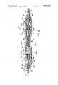
- FIG. 1is an elevational sectional view of a housing of the invention with a component and a strain-relief subassembly therein;
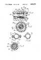
- FIG. 2is a sectional view taken along the line 2--2 of FIG. 1;
- FIG. 3is a sectional view taken along the line 3--3 of FIG. 1;
- FIG. 4is an enlarged sectional view of the strain-relief subassembly
- FIG. 5is a sectional view of an embodiment of a housing
- FIG. 6is a sectional view of an alternate embodiment of a housing.
- FIG. 1a strain-relief, fiber optic component housing assembly 10 having an elongated, substantially tubular body 12 with a longitudinal axis 14.
- the body 12has a first internal portion 16 for mounting a component 18; e.g., a fiber optic splice of the type shown in U.S. Pat. No. 4,257,674.
- the first internal portionis centrally located.
- Second internal portions 20a and 20bare positioned on either side of central portion 16.
- Each of the second internal portionshas, respectively, an inner circumferential wall 22a, 22b, provided with a plurality of inwardly projecting, radially spaced ribs 24a, 24b.
- the ribsare preferably "V" shaped in cross-section and have a given longitudinal extent when measured along the longitudinal axis 14.
- Optical fiber cables 26are positioned in the housing body 12 substantially along the axis 14.
- the fibers 28terminate in component 18, which as noted above, can be a splice of the type shown in U.S. Pat. No. 4,257,674 and comprising elastomeric portions 34, 36 enclosed in a glass tube 38 (see FIG. 3).
- a pair of strain-relief subassemblies 40a and 40bare also provided.
- the subassemblies 40a and 40beach include a first tubular member 42 (seen most clearly in FIGS. 2 and 4) having an inside diameter matching the outside diameter of cable 26.
- the outside diameter 44 of member 42is roughened, as by knurling.
- the member 42is fitted over cable 26 and fibrous material 30 is folded thereover to engage the roughened surface 44.
- a second tubular member 46has an inside diameter formed to fit over the fibrous material 30 and first tubular member 42 and is positioned thereover and fixed thereto, as by crimping.
- Engaging means 48is provided at one end of second tubular member 42 and can be an annular flange 50.
- the first tubular member 42is formed from a relatively non-compressible material, e.g., steel; and the second tubular member 46 is formed from a relatively compressible material, e.g., brass.
- the housing assembly body 12which can be a suitable plastic or hard rubber material, can be formed in two longitudinal halves 12a and 12b, as shown in FIG. 5, which can be joined by bolts 52 and nuts 54; or as a hinged assembly 12c such as is shown in FIG. 6.
- the latter assemblycan be held together with plastic ties 55 (see FIG. 1) or, if environmental integrity is necessary, the halves can be cemented.
- a fiber optic component 18is placed within first internal portion 16 of tubular body 12 whereat it is cushioned by ribs 56 (see FIG. 3).
- strain-relief subassemblies 40a and 40bare fitted into the second internal portions 20a and 20b respectively, and the housing halves joined together. The joining forces the external edge of flanges 50 to penetrate the ribs 24a and 24b, thus providing strain relief for the enclosed component 18.
- Additional strain reliefcan be provided by forming the terminal ends 56a and 56b with at least one cable biting portion 58, which can be in the form of a reduced diameter.
- the strainis applied to the fibrous material during sustained pulls and stresses.
- the housingis reusable, and the location of the strain-relief subassemblies on the cable is not critical so long as the flanges 50 will engage the crush ribs 24a and 24b.
- the knurled first memberallows the fibrous material to be displaced between the grooves, making an extremely tight and secure connection.
- the entire splice and strain-reliefcan be accomplished and then placed into the housing.
Landscapes
- Physics & Mathematics (AREA)
- General Physics & Mathematics (AREA)
- Optics & Photonics (AREA)
- Mechanical Coupling Of Light Guides (AREA)
Abstract
Description
Claims (5)
Priority Applications (1)
| Application Number | Priority Date | Filing Date | Title |
|---|---|---|---|
| US07/141,816US4804252A (en) | 1988-01-11 | 1988-01-11 | Housing for a fiber optic component |
Applications Claiming Priority (1)
| Application Number | Priority Date | Filing Date | Title |
|---|---|---|---|
| US07/141,816US4804252A (en) | 1988-01-11 | 1988-01-11 | Housing for a fiber optic component |
Publications (1)
| Publication Number | Publication Date |
|---|---|
| US4804252Atrue US4804252A (en) | 1989-02-14 |
Family
ID=22497392
Family Applications (1)
| Application Number | Title | Priority Date | Filing Date |
|---|---|---|---|
| US07/141,816Expired - Fee RelatedUS4804252A (en) | 1988-01-11 | 1988-01-11 | Housing for a fiber optic component |
Country Status (1)
| Country | Link |
|---|---|
| US (1) | US4804252A (en) |
Cited By (7)
| Publication number | Priority date | Publication date | Assignee | Title |
|---|---|---|---|---|
| US4834489A (en)* | 1988-01-11 | 1989-05-30 | Gte Products Corporation | Housing for a fiber optic component |
| US5142602A (en)* | 1989-09-05 | 1992-08-25 | Labinal Components & Systems, Inc. | Fiber optic connectors |
| US6272273B1 (en)* | 1999-09-02 | 2001-08-07 | Alcatel | Hermetic cable joint |
| US20040135737A1 (en)* | 2003-01-10 | 2004-07-15 | Itt Manufacturing Enterprises, Inc. | Fiber optic strain relief |
| EP2674797A1 (en)* | 2012-06-13 | 2013-12-18 | Tyco Electronics Nederland B.V. | Cable fixture assembly for fastening at least one cable at a cable carrier as well as a splitter comprising such cable fixture assembly |
| US8622481B2 (en) | 2011-01-25 | 2014-01-07 | Joy Mm Delaware, Inc. | Fiber optic cable protection in a mining system |
| CN111869002A (en)* | 2018-03-21 | 2020-10-30 | 泰连公司 | Antenna components for communication systems |
Citations (5)
| Publication number | Priority date | Publication date | Assignee | Title |
|---|---|---|---|---|
| US4168109A (en)* | 1977-05-18 | 1979-09-18 | Kabel-Und Metallwerke Gutehoffnungshuette Ag | Fiber optic connector apparatus with optical fibers having thermally deformable jacket material |
| US4319802A (en)* | 1979-10-17 | 1982-03-16 | Bunker Ramo Corporation | Stain relief for fiber optic connectors |
| US4588256A (en)* | 1982-09-07 | 1986-05-13 | Minnesota Mining And Manufacturing Company | Optical fiber connector |
| US4679895A (en)* | 1984-08-31 | 1987-07-14 | Amp Incorporated | Adhesiveless optical fiber connector |
| US4696537A (en)* | 1979-10-25 | 1987-09-29 | Allied Corporation | Connector for fiber optic cables |
- 1988
- 1988-01-11USUS07/141,816patent/US4804252A/ennot_activeExpired - Fee Related
Patent Citations (5)
| Publication number | Priority date | Publication date | Assignee | Title |
|---|---|---|---|---|
| US4168109A (en)* | 1977-05-18 | 1979-09-18 | Kabel-Und Metallwerke Gutehoffnungshuette Ag | Fiber optic connector apparatus with optical fibers having thermally deformable jacket material |
| US4319802A (en)* | 1979-10-17 | 1982-03-16 | Bunker Ramo Corporation | Stain relief for fiber optic connectors |
| US4696537A (en)* | 1979-10-25 | 1987-09-29 | Allied Corporation | Connector for fiber optic cables |
| US4588256A (en)* | 1982-09-07 | 1986-05-13 | Minnesota Mining And Manufacturing Company | Optical fiber connector |
| US4679895A (en)* | 1984-08-31 | 1987-07-14 | Amp Incorporated | Adhesiveless optical fiber connector |
Cited By (12)
| Publication number | Priority date | Publication date | Assignee | Title |
|---|---|---|---|---|
| US4834489A (en)* | 1988-01-11 | 1989-05-30 | Gte Products Corporation | Housing for a fiber optic component |
| US5142602A (en)* | 1989-09-05 | 1992-08-25 | Labinal Components & Systems, Inc. | Fiber optic connectors |
| USRE35935E (en)* | 1989-09-05 | 1998-10-27 | Labinal Components And Systems, Inc. | Fiber optic connectors |
| US6272273B1 (en)* | 1999-09-02 | 2001-08-07 | Alcatel | Hermetic cable joint |
| US20040135737A1 (en)* | 2003-01-10 | 2004-07-15 | Itt Manufacturing Enterprises, Inc. | Fiber optic strain relief |
| US7029184B2 (en) | 2003-01-10 | 2006-04-18 | Itt Manufacturing Enterprises, Inc. | Fiber optic strain relief |
| US8622481B2 (en) | 2011-01-25 | 2014-01-07 | Joy Mm Delaware, Inc. | Fiber optic cable protection in a mining system |
| US8950822B2 (en) | 2011-01-25 | 2015-02-10 | Joy Mm Delaware, Inc. | Fiber optic cable protection in a mining system |
| EP2674797A1 (en)* | 2012-06-13 | 2013-12-18 | Tyco Electronics Nederland B.V. | Cable fixture assembly for fastening at least one cable at a cable carrier as well as a splitter comprising such cable fixture assembly |
| US9383521B2 (en) | 2012-06-13 | 2016-07-05 | Te Connectivity Nederland B.V. | Cable fixture assembly for fastening at least one cable at a cable carrier as well as a splitter comprising such cable fixture assembly |
| CN111869002A (en)* | 2018-03-21 | 2020-10-30 | 泰连公司 | Antenna components for communication systems |
| CN111869002B (en)* | 2018-03-21 | 2022-04-12 | 泰连公司 | Antenna components for communication systems |
Similar Documents
| Publication | Publication Date | Title |
|---|---|---|
| US4815810A (en) | Housing for a fiber optic component | |
| US4826277A (en) | Transition of a multiple fiber cable to single fiber cable | |
| CN109270639B (en) | Outdoor optical fiber connector | |
| US4813760A (en) | Optical connector and plugs therefor | |
| EP0949521A3 (en) | Fiber optic connector assembly | |
| JPH0522210B2 (en) | ||
| JPH0711614B2 (en) | Optical fiber connector- | |
| JPS6325647B2 (en) | ||
| US4804252A (en) | Housing for a fiber optic component | |
| US4846564A (en) | Packaging a bare optical fiber interconnection | |
| KR20030060061A (en) | Contoured internal stub crimp backbone | |
| US4834489A (en) | Housing for a fiber optic component | |
| US5455880A (en) | Optical fiber cable connector assembly | |
| EP0655633B1 (en) | Apparatus for optically coupling an optical fiber to an electro-optic device | |
| HU214162B (en) | Matching-connecting device for matched connecting terminals of the optical conductors | |
| US4930856A (en) | Termination for flexible light-transmitting cables | |
| US3921257A (en) | Appliance for linear bodies | |
| US6485196B2 (en) | Optical fiber cord fixing component | |
| US8388237B2 (en) | Optical connector and method of assembling optical connector | |
| CA1141213A (en) | Fiber optic cable connector | |
| JPS5860712A (en) | Plug with boot | |
| JP2602548B2 (en) | Cable fixing mechanism for multi-core optical fiber cable connector | |
| JP2937155B2 (en) | Multi-core optical connector | |
| JPS5734514A (en) | Optical connector | |
| KR200161877Y1 (en) | Enclosure of horse-type optical junction box |
Legal Events
| Date | Code | Title | Description |
|---|---|---|---|
| AS | Assignment | Owner name:GTE PRODUCTS CORPORATION, A DE. CORP. Free format text:ASSIGNMENT OF ASSIGNORS INTEREST.;ASSIGNORS:BETZLER, MARK H.;SWANSON, STEVEN E.;REEL/FRAME:004820/0171;SIGNING DATES FROM 19871221 TO 19871225 Owner name:GTE PRODUCTS CORPORATION, A DE. CORP.,MASSACHUSETT Free format text:ASSIGNMENT OF ASSIGNORS INTEREST;ASSIGNORS:BETZLER, MARK H.;SWANSON, STEVEN E.;SIGNING DATES FROM 19871221 TO 19871225;REEL/FRAME:004820/0171 | |
| FEPP | Fee payment procedure | Free format text:PAYOR NUMBER ASSIGNED (ORIGINAL EVENT CODE: ASPN); ENTITY STATUS OF PATENT OWNER: LARGE ENTITY | |
| FPAY | Fee payment | Year of fee payment:4 | |
| AS | Assignment | Owner name:GTE CONTROL DEVICES INCORPORATED, MAINE Free format text:ASSIGNS THE ENTIRE INTEREST, SUBJECT TO CONDITIONS RECITED.;ASSIGNOR:GTE PRODUCTS CORPORATION A CORP. OF DELAWARE;REEL/FRAME:006192/0310 Effective date:19920529 | |
| FEPP | Fee payment procedure | Free format text:PAYER NUMBER DE-ASSIGNED (ORIGINAL EVENT CODE: RMPN); ENTITY STATUS OF PATENT OWNER: LARGE ENTITY Free format text:PAYOR NUMBER ASSIGNED (ORIGINAL EVENT CODE: ASPN); ENTITY STATUS OF PATENT OWNER: LARGE ENTITY | |
| FEPP | Fee payment procedure | Free format text:PAYOR NUMBER ASSIGNED (ORIGINAL EVENT CODE: ASPN); ENTITY STATUS OF PATENT OWNER: LARGE ENTITY Free format text:PAYER NUMBER DE-ASSIGNED (ORIGINAL EVENT CODE: RMPN); ENTITY STATUS OF PATENT OWNER: LARGE ENTITY | |
| AS | Assignment | Owner name:GTE CONTROL DEVICES OF PUERTO RICO INCORPORATED, C Free format text:ASSIGNMENT OF ASSIGNORS INTEREST;ASSIGNOR:GTE CONTROL DEVICES INCORPORATED;REEL/FRAME:006607/0279 Effective date:19930624 | |
| AS | Assignment | Owner name:SIECOR PUERTO RICO, INC., NORTH CAROLINA Free format text:ASSIGNMENT OF ASSIGNORS INTEREST;ASSIGNOR:GTE CONTROL DEVICES OF PUERTO RICO INCORPORATED;REEL/FRAME:006728/0486 Effective date:19930928 | |
| REMI | Maintenance fee reminder mailed | ||
| LAPS | Lapse for failure to pay maintenance fees | ||
| FP | Lapsed due to failure to pay maintenance fee | Effective date:19970219 | |
| STCH | Information on status: patent discontinuation | Free format text:PATENT EXPIRED DUE TO NONPAYMENT OF MAINTENANCE FEES UNDER 37 CFR 1.362 |