US4804000A - Dynamic sagittal knee test apparatus - Google Patents
Dynamic sagittal knee test apparatusDownload PDFInfo
- Publication number
- US4804000A US4804000AUS07/005,921US592187AUS4804000AUS 4804000 AUS4804000 AUS 4804000AUS 592187 AUS592187 AUS 592187AUS 4804000 AUS4804000 AUS 4804000A
- Authority
- US
- United States
- Prior art keywords
- patient
- measuring
- relative
- knee
- patella
- Prior art date
- Legal status (The legal status is an assumption and is not a legal conclusion. Google has not performed a legal analysis and makes no representation as to the accuracy of the status listed.)
- Expired - Lifetime
Links
- 210000003127kneeAnatomy0.000titleclaimsabstractdescription50
- 238000012360testing methodMethods0.000titleclaimsdescription21
- 210000000689upper legAnatomy0.000claimsabstractdescription28
- 230000033001locomotionEffects0.000claimsabstractdescription24
- 210000002303tibiaAnatomy0.000claimsabstractdescription23
- 210000004417patellaAnatomy0.000claimsdescription33
- 238000006073displacement reactionMethods0.000claimsdescription32
- 210000002414legAnatomy0.000claimsdescription28
- 238000005259measurementMethods0.000claimsdescription24
- 210000001699lower legAnatomy0.000claimsdescription7
- 210000003423ankleAnatomy0.000claimsdescription5
- 208000027418Wounds and injuryDiseases0.000description4
- 230000006378damageEffects0.000description4
- 208000014674injuryDiseases0.000description4
- 206010065564Floating patellaDiseases0.000description3
- 238000000034methodMethods0.000description3
- 206010065433Ligament ruptureDiseases0.000description2
- 230000002159abnormal effectEffects0.000description2
- 238000006243chemical reactionMethods0.000description2
- 230000007812deficiencyEffects0.000description2
- 238000003745diagnosisMethods0.000description2
- 210000002683footAnatomy0.000description2
- 210000001264anterior cruciate ligamentAnatomy0.000description1
- 244000309466calfSpecies0.000description1
- 210000004439collateral ligamentAnatomy0.000description1
- 230000000052comparative effectEffects0.000description1
- 230000006835compressionEffects0.000description1
- 238000007906compressionMethods0.000description1
- 238000004590computer programMethods0.000description1
- 238000010276constructionMethods0.000description1
- 230000006735deficitEffects0.000description1
- 238000001514detection methodMethods0.000description1
- 238000002405diagnostic procedureMethods0.000description1
- 230000009977dual effectEffects0.000description1
- 238000011156evaluationMethods0.000description1
- 210000003041ligamentAnatomy0.000description1
- 238000011160researchMethods0.000description1
- 230000005945translocationEffects0.000description1
- 230000000007visual effectEffects0.000description1
Images


Classifications
- A—HUMAN NECESSITIES
- A61—MEDICAL OR VETERINARY SCIENCE; HYGIENE
- A61B—DIAGNOSIS; SURGERY; IDENTIFICATION
- A61B5/00—Measuring for diagnostic purposes; Identification of persons
- A61B5/45—For evaluating or diagnosing the musculoskeletal system or teeth
- A61B5/4533—Ligaments
- A—HUMAN NECESSITIES
- A61—MEDICAL OR VETERINARY SCIENCE; HYGIENE
- A61B—DIAGNOSIS; SURGERY; IDENTIFICATION
- A61B5/00—Measuring for diagnostic purposes; Identification of persons
- A61B5/103—Measuring devices for testing the shape, pattern, colour, size or movement of the body or parts thereof, for diagnostic purposes
- A—HUMAN NECESSITIES
- A61—MEDICAL OR VETERINARY SCIENCE; HYGIENE
- A61B—DIAGNOSIS; SURGERY; IDENTIFICATION
- A61B5/00—Measuring for diagnostic purposes; Identification of persons
- A61B5/45—For evaluating or diagnosing the musculoskeletal system or teeth
- A61B5/4528—Joints
- A—HUMAN NECESSITIES
- A61—MEDICAL OR VETERINARY SCIENCE; HYGIENE
- A61B—DIAGNOSIS; SURGERY; IDENTIFICATION
- A61B5/00—Measuring for diagnostic purposes; Identification of persons
- A61B5/68—Arrangements of detecting, measuring or recording means, e.g. sensors, in relation to patient
- A61B5/6801—Arrangements of detecting, measuring or recording means, e.g. sensors, in relation to patient specially adapted to be attached to or worn on the body surface
- A61B5/6813—Specially adapted to be attached to a specific body part
- A61B5/6828—Leg
- A—HUMAN NECESSITIES
- A61—MEDICAL OR VETERINARY SCIENCE; HYGIENE
- A61B—DIAGNOSIS; SURGERY; IDENTIFICATION
- A61B5/00—Measuring for diagnostic purposes; Identification of persons
- A61B5/68—Arrangements of detecting, measuring or recording means, e.g. sensors, in relation to patient
- A61B5/6801—Arrangements of detecting, measuring or recording means, e.g. sensors, in relation to patient specially adapted to be attached to or worn on the body surface
- A61B5/683—Means for maintaining contact with the body
- A61B5/6831—Straps, bands or harnesses
Definitions
- a microfiche appendix consisting of one sheet with seventy-eight framesis available.
- This inventionrelates to apparatus for measuring ligamentous insufficiency in the knee to enable a physician to provide a diagnosis of injury or abnormal operation for evaluation of different treatment methods.
- abnormal motion between the tibia and the femurwas detected by a physician by manipulation of the leg by hand.
- the motion of a leg with a ligament tearis subtle and difficult to quantify or even compare with the patient's uninjured leg.
- a normal kneemay have a substantial motion, it is desirable to quantitatively measure the displacement to allow an accurate comparison between the patient's normal and injured knees to determine the extent of injury. Further, it is desirable to quantify such measurements to compare motion of the patient's knee with statistical norms or with past records to monitor the progress of treatment.
- an electromechanical instrumenthas been devised for measuring the anterior drawer in the legs of normal volunteers and patients with known anterior cruciate deficits in a clinical research study, the device has certain disadvantages.
- the instrumentis expensive and bulky and is not autoclavable to allow for its use in the operating room. Further, the instrument cannot measure knee motions of the knee when the patient is standing or walking.
- the apparatus of this inventionis autoclavable and is designed for use in both the 20° anterior draw and 90° anterior draw tests and without refitting is designed for use in measuring posterior excursions. It is believed that measurement of both anterior and posterior excursions provides the physician with the maximum useful data for proper diagnosis and treatment.
- the first of such instrumentsutilized a modified dental chair and measurements of knee laxity were obtained by measuring motion relative to the chair. This required that the patient's leg be immobilized at various points to assure accuracy of the measurements.
- Improved devicessuch as that disclosed in our U.S. Pat. No. 4,534,364, issued Aug. 13, 1985, entitled, "Sagittal Knee Test Apparatus," provide exoskeletal frame structures that permit comparative measurements to be taken from the light weight frame structure itself, thus freeing the patient from the chair and improving the accuracy of measurements.
- Such apparatuswas nevertheless designed for operation while a patient was seated, preferably with an adjustable support device for the lower legs as described in the cited reference. While the improved device described was mechanical in operation, other devices for anterior/posterior laxity measurement have utilized electronic, leg mounted measuring means in conjunction with leg supports of various types.
- varus-valgus laxity and axial rotation of the tibia relative to the femurare advantageous to measure varus-valgus laxity and axial rotation of the tibia relative to the femur.
- the measuring frameworkIn designing equipment for measuring knee laxities it is desirable to have the measuring framework connect to the body at long skeletal prominences with minimal restriction of normal joint motions.
- the frameworkmust therefore be light in weight and mechanically self-contained without mechanical connection to external structures.
- the exoskeletal structureshould permit ambulatory motion to allow measurements to be obtained during normal movement such as walking as well as during conventional, contrived examination procedures.
- an ambulatory exoskeletal frameworkhas been experimentally constructed for hip motions including tibial rotations, heretofore such a structure adapted to measure anterior/posterior and varus-valgus laxities as well as tibial rotation has not been devised.
- the dynamic sagittal knee testor of this inventionis designed to perform the standard knee laxity tests at various measured flexion angles of the lower leg and uniquely generate laxity measurements while walking.
- the dynamic sagittal knee test apparatus of this inventionrelates to those devices used to measure laxity or deficiencies in the knee, usually to diagnose injuries often resulting from sports where the foot is immobilized and dynamic forces are applied to the leg or knee as in cleat sports and skiing.
- Laxity measuring instrumentshave become sufficiently sensitive that more subtle deficiencies in the knee than major ligament tears are detectable.
- the dynamic knee test apparatus of this inventionis a light weight, exoskeletal frame that is attached to the user's upper and lower leg and is used in conjunction with an adjustable leg support seat as described in our referenced patent or without such seat with the patient standing or walking.
- Other devicesdo not have this versatility which permits measurements to be taken when the patient applies his natural weight to the knee as well as external forces.
- the apparatus of the inventionmeasures varus-valgus laxity and axial rotation of the tibia while recording the flexion angle of the leg.
- the measurementsare electronically taken and coordinated by a personal computer using a software program for instantaneous display on a monitor. Permanent records may be obtained using conventional accessory printers.
- the knee test apparatusattaches a light weight tubular reference element to each skeletal segment of interest and then measures relative motions between the reference elements by linking structures and displacement sensing transducers.
- a first elongated, tubular elementis mounted to the thigh on a pair of displaced mounting pads strapped to the upper and lower thigh such that the tubular rod is aligned with the femur.
- the thighlacks the body prominences preferred for detecting subtle motions of the exoskeleton
- the femur elementis the reference element, and visual alignment with secure strapping is sufficient for the rod to maintain its position with respect to the femur during translocations of the tibia.
- a second elongated, light-weight, tubular elementis mounted to the tibia on a pair of displaced mounting pads seated on bony prominences such that the tubular rod parallels all movements of the tibia.
- Interconnecting the femoral rod and the tibial rodis a side linkage with a first radial transducer positioned at the axis of overall knee flexion to detect the relative angle of tibia and femur and alternate second and third radial transducers to selectively detect axial rotation or varus-valgus motions respectively.
- the former motionis of the type induced by twisting the foot and the latter by side forces on the lower leg with the knee immobilized. Data obtained from measurement of these motions is particularly useful in determining exactly which ligament in the knee is damaged or severed and often where it is damaged.
- the standard anterior/posterior laxity measurementsare taken by a fourth transducer connected to the support linkage of a floating patella pad positioned at the end of the tibial rod in contact with the patella.
- the patella padis proximate the upper support pad which contacts the bony tibial tubercle. Since the patella follows the femur, subtle fore and aft displacements of the tibia relative to the femur are accurately represented by displacements of the patella pad and tibial tubercle contact pad.
- a small spring in the patella pad linkagebiases the pad against the patella such that measurements can be taken while the patient is standing or walking.
- Signals from the sensorsare sent to a processor where the radial detections are translated, in most cases, to equivalent angular displacements which may be represented on conventional gauges or digital displays.
- the signalsare sent to a computer processor where various two dimensional displays graphically depict various motions as desired by the diagnostician.
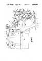
- FIG. 1is a side elevational view of the knee test apparatus installed on a patient seated on a leg support device.
- FIG. 2is a top assembly view partially fragmented of the test apparatus of FIG. 1 in an extended position.
- FIG. 3is a partial top assembly view of the test apparatus of FIG. 2 in an alternate connection configuration.
- FIG. 4is a top view of a spanning linkage assembly.
- FIG. 5is a side view of the assembly of FIG. 4.
- FIG. 6is a side view of a patella pad linkage assembly.
- FIG. 7is an end view of the assembly of FIG. 6.
- FIG. 8is a side elevational view of a force applicator in schematic conjunction with a computer.
- the dynamic knee test apparatus designated by the reference numeral 10is shown mounted on a seated patient 12 shown in phantom.
- the patient's legis supported on an adjustable leg support 14 as described in our referenced patent.
- the leg support 14is employed in performing the traditional anterior/posterior force applications in full extension, 20° flexion flexion, as well as tibial rotation and varus-valgus moment angulation.
- Forceis applied by hand or using a mechanical force applicator of the type described in the reference application or an applicator 6 of similar configuration shown in FIG. 8 having an electronic pressure sensitive transducer unit 17 for generating electrical signals corresponding to the value of force.
- the force applicatoris primarily used for anterior/posterior tests.
- the tibial rod 26is supported by an upper pad 28 and support post 30 slidably adjustable by screw clamp 32, and a lower pad 34 and support post 36, also slidably adjustable by a screw clamp 38.
- the upper pad 28is positioned on the tibial tubercle, a stable location proximate the patella, and the strap 40 tightened.
- the lower pad 34is positioned on the tibia at the lower shin above the ankle and the strap 42 tightened. The adjustments are to insure that the patella pad 22 is properly positioned against the center of the patella with the tibial rod support pads appropriately positioned on relatively stable bony prominances.
- a femoral rod 44is supported by an upper pad 46 and adjustable support member 48 and a lower pad 50 adjustable and support member 52. Straps 54 and 56 retain the respective pads firmly against the patient's thigh.
- the femoral rod 44is connected to the tibial rod 26 by a linkage assembly 58. Although the femoral rod 44 is fastened to the patient at relatively fleshy areas of the leg, the minimum friction generated by the linkage assembly eliminates detectable dislocations of the femoral rod during displacements of the tibial rod 26.
- a spanning segment 60 of the linkage assembly 58is arranged in two different configurations depending whether axial rotations of the tibial are to be measured, as shown in the assembly of FIGS. 1 and 2, or varus-valgus displacements are to be measured as shown in the partial assembly of FIG. 3.
- the femoral rod 44has a perpendicular side post 62 connected to the end of the femoral rod 44 by screw clamp 64.
- the distal end of the side post 62has a clamp 66 connecting a perpendicular junction peg 67.
- the junction peg 67seats a vertical side post 68 with end clamps 69 and 70, the lower of which connects to a transducer post 71.
- the transducer post 71has a collar clamp 72 which encircles the neck of the housing 74 of a flexion angle transducer 76 that senses axial motion by a projecting, rotatable transducer shaft 78. Adjustment of the angle of the side post 62 and its position on the femoral rod 44 will position the axis of the transducer shaft 78 proximate the pivot axis of the knee.
- the tibial rod 26also has a side post 80 with a screw clamp 82 for projecting the post perpendicular to the rod 26.
- the tibial post 80is truncated to engage a cross post 84 in its end clamp 86.
- the cross post 84has a varus-valgus transducer 88 clamped in a collar clamp 90 with its sensor shaft 92 clamped by a dual pin clamp 94 to an actuator lever 96 that is disengaged.
- Between the post clamp 86 and the transducer clamp 90is an extension post clamp 98 and an extension post 100.
- an extension post clamp 102 at the distal end of the extension post 100is an axial rotation transducer 104.
- the shaft 106 of the axial rotation transducer 104has a cross pin clamp 107 on the shaft with a cross pin 108 to provide a crank arm for registering rotations of the tibial rod 26 relative to the femoral rod 44.
- the cross pin 108is connected to the spanning segment 60, which in turn is connected to the flexion angle transducer 76.
- the spanning segment 60is designed to permit displacement differentials, that is, variations in the distance between the axial transducer 104 and the flexion transducer 74 with minimal distortion in flexion angle measurements or axial rotation measurements since movement of the knee is not truly axial.
- the spanning segmenthas a central parallel linkage unit 110 shown in greater detail in FIGS. 4 and 5.
- the parallel linkage unit 110has a top link 112 and a pair of bottom links 114 connected to pivots 116 and 118 respectively in end brackets 120 and 122.
- the end bracketssupport pivotal shafts 124 and. 126 with connecting links 128 and 130 being fixed on the shafts but free to pivot with the shafts.
- Connecting link 128has a clamp 132 that engages a crank pin 134 that is mounted perpendicular to the flexion transducer shaft 78 by a cross pin clamp 136, as shown in FIG. 1.
- Connecting link 130is a long extension with an end yoke link 138 pivotally connected in one alternative to the connecting link and clamped to the crank pin 108 of the rotational transducer shaft 106 by integral and clamp 139 as shown in FIGS. 1 and 2. Since the axial rotational transducer shaft is perpendicular to the flexion transducer shaft, the spanning segment 60 transmits flexion angle change to the flexion transducer 76 and axial rotation changes to the axial transducer 104. The third axis of angulation is absorbed the linkage.
- the linkage assemblyis oriented to detect varus-valgus displacements as well as flexion angulation.
- the spanning segment 60is reoriented such that the clamp 132 of the connecting link 128 engages an elongated crank pin 140 connected to the flexion transducer shaft 78 by a cross pin clamp 142.
- the parallel link unit 110 shown on endhas its connected extension link 130 directed toward the actuator lever 96 of the varus-valgus transducer 88.
- the yoke link 138has its end clamp 139 clamped to the actuator lever 96.
- Angular side displacements of the leg using medial laxity proceduresare customarily accomplished by pushing with one hand on the outside of the knee while pulling with the other hand on the inside of the ankle or vice-versa.
- Medial-lateral knee displacementsare instantly detected by angular rotation of the varus-valgus transducer shaft.
- Flexion angleis detected by the flexion transducer in the same manner as previously described.
- FIGS. 6 and 7the linkage assembly 24 for detecting fore and aft displacements of the tibia relative to the femur is detailed.
- the floating patella pad 22 shown in FIGS. 1 and 2is fastened to the end of a shaft 146.
- the patella shaftis slidable in a end mount 148 having a side split to accommodate a clamping screw 150 for securing the position of the shaft 146 and hence the patella pad 22 to the linkage assembly 24.
- the parallel links 152 and 154have displaced pivotal connections to a transducer mount 156 at the other end.
- the transducer mount 156is slidably clamped by clamp screw 158 to the end of the tibial rod 26, and supports an anterior/posterior laxity transducer 160.
- the axial shaft 162 of the transducerforms the pivot connection for the upper link 152 which is clamped by screw 163 to the shaft.
- the parallel linkagemaintains the patella shaft in a substantially perpendicular orientation to the patella during fore and aft excursions of the tibia.
- Axial rotation of the transducer shaft 162is calibrated to linear displacements of the patella pad relative to the tibial rod.
- the transduceris conveniently "zeroed” by extending the end of the rod 26 into a socket 164 in the end mount 148. The engaged position is also convenient for storage.
- a spring 166 on a pivot extension 168 for the lower link 154engages the pivotal link 154 and stationary mount 156 to bias the linkage and hence the patella pad 22 against the patient's knee.
- the four transducersare preferably highly sensitive potentiometers which, from a low voltage bus line, can develop a convenient low voltage analog signal for angular displacements. In the case of the anterior/posterior transducer the signal can be easily converted to represent linear displacements. These signals can be easily read by a simple volt meter for manual conversion, or a conventional signal processor for a more representative reading or record.
- the four electrical signal cables, 170, 172, 174 and 176 from the four transactionsare combined in a junction box 178 mounted on the tibial rod 26 by a clamp bracket 180 as shown in FIG. 2.
- the junction boxincludes a multi-line socket 181 for a terminal plug 182 of a multi-line cable 184 leading to a signal processor.
- a force applicator 186 having an electrical signal output 188is shown in FIG. 8.
- the electrical signal or signalsare generated by the pressure sensitive transducers 190 within the casing 192 on the shank 194 of the applicator 186.
- the transducersrespond to compression on pushing the contact pad 196 by the handle 198, as in pushing the shin, or to tension on pulling the contact pad 196 by the handle, as in pulling the calf.
- the dynamic knee tester of this inventionpermits measurements while the patient stands with applied frontal anterior or lateral forces and even permits graphical plots to be taken of various laxities while the patient normally walks. Because of the vastly expanded capabilities of the present system, many valuable diagnostic tests have yet to be devised. However, it is clear that study of the kinematics of the knee will be substantially advanced through use of the subject apparatus.
- a typical computer program listing for generating useful data and plottingsis filed in an appendix to this application.
- the listingis in microfiche form and consists of one sheet with seventy-eight frames.
Landscapes
- Health & Medical Sciences (AREA)
- Life Sciences & Earth Sciences (AREA)
- Surgery (AREA)
- Biomedical Technology (AREA)
- Veterinary Medicine (AREA)
- Public Health (AREA)
- Physics & Mathematics (AREA)
- Dentistry (AREA)
- Biophysics (AREA)
- Pathology (AREA)
- Engineering & Computer Science (AREA)
- Oral & Maxillofacial Surgery (AREA)
- Heart & Thoracic Surgery (AREA)
- Medical Informatics (AREA)
- Molecular Biology (AREA)
- General Health & Medical Sciences (AREA)
- Animal Behavior & Ethology (AREA)
- Rehabilitation Therapy (AREA)
- Rheumatology (AREA)
- Orthopedic Medicine & Surgery (AREA)
- Measurement Of The Respiration, Hearing Ability, Form, And Blood Characteristics Of Living Organisms (AREA)
Abstract
Description
A microfiche appendix consisting of one sheet with seventy-eight frames is available.
This invention relates to apparatus for measuring ligamentous insufficiency in the knee to enable a physician to provide a diagnosis of injury or abnormal operation for evaluation of different treatment methods. In the past, abnormal motion between the tibia and the femur was detected by a physician by manipulation of the leg by hand. Often the motion of a leg with a ligament tear is subtle and difficult to quantify or even compare with the patient's uninjured leg. Because a normal knee may have a substantial motion, it is desirable to quantitatively measure the displacement to allow an accurate comparison between the patient's normal and injured knees to determine the extent of injury. Further, it is desirable to quantify such measurements to compare motion of the patient's knee with statistical norms or with past records to monitor the progress of treatment.
While an electromechanical instrument has been devised for measuring the anterior drawer in the legs of normal volunteers and patients with known anterior cruciate deficits in a clinical research study, the device has certain disadvantages. The instrument is expensive and bulky and is not autoclavable to allow for its use in the operating room. Further, the instrument cannot measure knee motions of the knee when the patient is standing or walking.
The apparatus of this invention is autoclavable and is designed for use in both the 20° anterior draw and 90° anterior draw tests and without refitting is designed for use in measuring posterior excursions. It is believed that measurement of both anterior and posterior excursions provides the physician with the maximum useful data for proper diagnosis and treatment.
The first of such instruments utilized a modified dental chair and measurements of knee laxity were obtained by measuring motion relative to the chair. This required that the patient's leg be immobilized at various points to assure accuracy of the measurements. Improved devices, such as that disclosed in our U.S. Pat. No. 4,534,364, issued Aug. 13, 1985, entitled, "Sagittal Knee Test Apparatus," provide exoskeletal frame structures that permit comparative measurements to be taken from the light weight frame structure itself, thus freeing the patient from the chair and improving the accuracy of measurements. Such apparatus was nevertheless designed for operation while a patient was seated, preferably with an adjustable support device for the lower legs as described in the cited reference. While the improved device described was mechanical in operation, other devices for anterior/posterior laxity measurement have utilized electronic, leg mounted measuring means in conjunction with leg supports of various types.
In addition to anterior/posterior laxity measurement, it is advantageous to measure varus-valgus laxity and axial rotation of the tibia relative to the femur. These additional measurements greatly enhance the ability to correctly determine the severity of injury and in particular whether it is the anterior cruciate ligament, medial collateral ligament or both that are damaged.
In designing equipment for measuring knee laxities it is desirable to have the measuring framework connect to the body at long skeletal prominences with minimal restriction of normal joint motions. The framework must therefore be light in weight and mechanically self-contained without mechanical connection to external structures. Preferably, the exoskeletal structure should permit ambulatory motion to allow measurements to be obtained during normal movement such as walking as well as during conventional, contrived examination procedures. Although such an ambulatory exoskeletal framework has been experimentally constructed for hip motions including tibial rotations, heretofore such a structure adapted to measure anterior/posterior and varus-valgus laxities as well as tibial rotation has not been devised. The dynamic sagittal knee testor of this invention is designed to perform the standard knee laxity tests at various measured flexion angles of the lower leg and uniquely generate laxity measurements while walking.
The dynamic sagittal knee test apparatus of this invention relates to those devices used to measure laxity or deficiencies in the knee, usually to diagnose injuries often resulting from sports where the foot is immobilized and dynamic forces are applied to the leg or knee as in cleat sports and skiing. Laxity measuring instruments have become sufficiently sensitive that more subtle deficiencies in the knee than major ligament tears are detectable.
The dynamic knee test apparatus of this invention is a light weight, exoskeletal frame that is attached to the user's upper and lower leg and is used in conjunction with an adjustable leg support seat as described in our referenced patent or without such seat with the patient standing or walking. Other devices do not have this versatility which permits measurements to be taken when the patient applies his natural weight to the knee as well as external forces. In addition to the conventional anterior/posterior laxity measurements to which conventional portable knee test apparatus is limited, the apparatus of the invention measures varus-valgus laxity and axial rotation of the tibia while recording the flexion angle of the leg.
The measurements are electronically taken and coordinated by a personal computer using a software program for instantaneous display on a monitor. Permanent records may be obtained using conventional accessory printers.
In construction, the knee test apparatus attaches a light weight tubular reference element to each skeletal segment of interest and then measures relative motions between the reference elements by linking structures and displacement sensing transducers. Thus, in the preferred embodiment a first elongated, tubular element is mounted to the thigh on a pair of displaced mounting pads strapped to the upper and lower thigh such that the tubular rod is aligned with the femur. While the thigh lacks the body prominences preferred for detecting subtle motions of the exoskeleton, the femur element is the reference element, and visual alignment with secure strapping is sufficient for the rod to maintain its position with respect to the femur during translocations of the tibia.
A second elongated, light-weight, tubular element is mounted to the tibia on a pair of displaced mounting pads seated on bony prominences such that the tubular rod parallels all movements of the tibia. Interconnecting the femoral rod and the tibial rod is a side linkage with a first radial transducer positioned at the axis of overall knee flexion to detect the relative angle of tibia and femur and alternate second and third radial transducers to selectively detect axial rotation or varus-valgus motions respectively. The former motion is of the type induced by twisting the foot and the latter by side forces on the lower leg with the knee immobilized. Data obtained from measurement of these motions is particularly useful in determining exactly which ligament in the knee is damaged or severed and often where it is damaged.
The standard anterior/posterior laxity measurements are taken by a fourth transducer connected to the support linkage of a floating patella pad positioned at the end of the tibial rod in contact with the patella. The patella pad is proximate the upper support pad which contacts the bony tibial tubercle. Since the patella follows the femur, subtle fore and aft displacements of the tibia relative to the femur are accurately represented by displacements of the patella pad and tibial tubercle contact pad. A small spring in the patella pad linkage biases the pad against the patella such that measurements can be taken while the patient is standing or walking.
Signals from the sensors are sent to a processor where the radial detections are translated, in most cases, to equivalent angular displacements which may be represented on conventional gauges or digital displays. Preferably the signals are sent to a computer processor where various two dimensional displays graphically depict various motions as desired by the diagnostician.
FIG. 1 is a side elevational view of the knee test apparatus installed on a patient seated on a leg support device.
FIG. 2 is a top assembly view partially fragmented of the test apparatus of FIG. 1 in an extended position.
FIG. 3 is a partial top assembly view of the test apparatus of FIG. 2 in an alternate connection configuration.
FIG. 4 is a top view of a spanning linkage assembly.
FIG. 5 is a side view of the assembly of FIG. 4.
FIG. 6 is a side view of a patella pad linkage assembly.
FIG. 7 is an end view of the assembly of FIG. 6.
FIG. 8 is a side elevational view of a force applicator in schematic conjunction with a computer.
Referring to FIG. 1 the dynamic knee test apparatus designated by thereference numeral 10 is shown mounted on a seated patient 12 shown in phantom. The patient's leg is supported on anadjustable leg support 14 as described in our referenced patent. Theleg support 14 is employed in performing the traditional anterior/posterior force applications in full extension, 20° flexion flexion, as well as tibial rotation and varus-valgus moment angulation. Force is applied by hand or using a mechanical force applicator of the type described in the reference application or an applicator 6 of similar configuration shown in FIG. 8 having an electronic pressuresensitive transducer unit 17 for generating electrical signals corresponding to the value of force. The force applicator is primarily used for anterior/posterior tests. With the knee test apparatus strapped to the patient and the patient correspondingly strapped at his ankles to theextension 18 of theleg support 14 and at his thighs to theseat 20, force is applied below the knee to the front or back of the tibia. Deflections of the tibia relative to the femur are detected by afloating patella pad 22 which contacts the patella. Thepatella pad 22 is connected by a four barparallelogram linkage assembly 24, shown in greater detail in FIGS. 6 and 7, to an elongated, light-weight,tibial rod 26 longitudinally positioned over the shin generally parallel to the axis of the tibia.
Thetibial rod 26 is supported by anupper pad 28 and supportpost 30 slidably adjustable byscrew clamp 32, and alower pad 34 andsupport post 36, also slidably adjustable by ascrew clamp 38. Theupper pad 28 is positioned on the tibial tubercle, a stable location proximate the patella, and thestrap 40 tightened. Thelower pad 34 is positioned on the tibia at the lower shin above the ankle and thestrap 42 tightened. The adjustments are to insure that thepatella pad 22 is properly positioned against the center of the patella with the tibial rod support pads appropriately positioned on relatively stable bony prominances.
Similarly, a femoral rod 44 is supported by anupper pad 46 andadjustable support member 48 and alower pad 50 adjustable andsupport member 52.Straps 54 and 56 retain the respective pads firmly against the patient's thigh. The femoral rod 44 is connected to thetibial rod 26 by alinkage assembly 58. Although the femoral rod 44 is fastened to the patient at relatively fleshy areas of the leg, the minimum friction generated by the linkage assembly eliminates detectable dislocations of the femoral rod during displacements of thetibial rod 26.
A spanningsegment 60 of thelinkage assembly 58 is arranged in two different configurations depending whether axial rotations of the tibial are to be measured, as shown in the assembly of FIGS. 1 and 2, or varus-valgus displacements are to be measured as shown in the partial assembly of FIG. 3. Referring to FIGS. 1 and 2, the femoral rod 44 has aperpendicular side post 62 connected to the end of the femoral rod 44 byscrew clamp 64. The distal end of theside post 62 has aclamp 66 connecting aperpendicular junction peg 67. The junction peg 67 seats a vertical side post 68 with end clamps 69 and 70, the lower of which connects to atransducer post 71. Thetransducer post 71 has acollar clamp 72 which encircles the neck of the housing 74 of aflexion angle transducer 76 that senses axial motion by a projecting, rotatable transducer shaft 78. Adjustment of the angle of theside post 62 and its position on the femoral rod 44 will position the axis of the transducer shaft 78 proximate the pivot axis of the knee.
Thetibial rod 26 also has aside post 80 with ascrew clamp 82 for projecting the post perpendicular to therod 26. Thetibial post 80 is truncated to engage across post 84 in itsend clamp 86. Thecross post 84 has a varus-valgus transducer 88 clamped in acollar clamp 90 with itssensor shaft 92 clamped by adual pin clamp 94 to anactuator lever 96 that is disengaged. Between thepost clamp 86 and thetransducer clamp 90 is anextension post clamp 98 and anextension post 100. In ascrew clamp 102 at the distal end of theextension post 100 is anaxial rotation transducer 104. Theshaft 106 of theaxial rotation transducer 104 has across pin clamp 107 on the shaft with across pin 108 to provide a crank arm for registering rotations of thetibial rod 26 relative to the femoral rod 44. In the arrangement of FIG. 2 thecross pin 108 is connected to the spanningsegment 60, which in turn is connected to theflexion angle transducer 76. The spanningsegment 60 is designed to permit displacement differentials, that is, variations in the distance between theaxial transducer 104 and the flexion transducer 74 with minimal distortion in flexion angle measurements or axial rotation measurements since movement of the knee is not truly axial.
The spanning segment has a centralparallel linkage unit 110 shown in greater detail in FIGS. 4 and 5. Theparallel linkage unit 110 has atop link 112 and a pair ofbottom links 114 connected topivots end brackets pivotal shafts 124 and. 126 with connectinglinks Connecting link 128 has aclamp 132 that engages acrank pin 134 that is mounted perpendicular to the flexion transducer shaft 78 by across pin clamp 136, as shown in FIG. 1.
Referring to the alternate connection arrangement of FIG. 3, the linkage assembly is oriented to detect varus-valgus displacements as well as flexion angulation. In FIG. 3 the spanningsegment 60 is reoriented such that theclamp 132 of the connectinglink 128 engages an elongated crankpin 140 connected to the flexion transducer shaft 78 by across pin clamp 142. Theparallel link unit 110 shown on end has its connected extension link 130 directed toward theactuator lever 96 of the varus-valgus transducer 88. Theyoke link 138 has itsend clamp 139 clamped to theactuator lever 96. Angular side displacements of the leg using medial laxity procedures, are customarily accomplished by pushing with one hand on the outside of the knee while pulling with the other hand on the inside of the ankle or vice-versa. Medial-lateral knee displacements are instantly detected by angular rotation of the varus-valgus transducer shaft. Flexion angle is detected by the flexion transducer in the same manner as previously described.
Referring now to FIGS. 6 and 7 thelinkage assembly 24 for detecting fore and aft displacements of the tibia relative to the femur is detailed. The floatingpatella pad 22 shown in FIGS. 1 and 2 is fastened to the end of ashaft 146. The patella shaft is slidable in aend mount 148 having a side split to accommodate a clampingscrew 150 for securing the position of theshaft 146 and hence thepatella pad 22 to thelinkage assembly 24. Theparallel links transducer mount 156 at the other end. Thetransducer mount 156 is slidably clamped byclamp screw 158 to the end of thetibial rod 26, and supports an anterior/posterior laxity transducer 160. Theaxial shaft 162 of the transducer forms the pivot connection for theupper link 152 which is clamped byscrew 163 to the shaft. The parallel linkage maintains the patella shaft in a substantially perpendicular orientation to the patella during fore and aft excursions of the tibia. Axial rotation of thetransducer shaft 162 is calibrated to linear displacements of the patella pad relative to the tibial rod. The transducer is conveniently "zeroed" by extending the end of therod 26 into asocket 164 in theend mount 148. The engaged position is also convenient for storage.
To insure that thepad 22 contacts the patella, aspring 166 on apivot extension 168 for thelower link 154 engages thepivotal link 154 andstationary mount 156 to bias the linkage and hence thepatella pad 22 against the patient's knee.
The four transducers are preferably highly sensitive potentiometers which, from a low voltage bus line, can develop a convenient low voltage analog signal for angular displacements. In the case of the anterior/posterior transducer the signal can be easily converted to represent linear displacements. These signals can be easily read by a simple volt meter for manual conversion, or a conventional signal processor for a more representative reading or record. The four electrical signal cables, 170, 172, 174 and 176 from the four transactions are combined in a junction box 178 mounted on thetibial rod 26 by aclamp bracket 180 as shown in FIG. 2. The junction box includes amulti-line socket 181 for aterminal plug 182 of amulti-line cable 184 leading to a signal processor.
Since it is preferred to apply measured force, particularly for the anterior/posterior tests, aforce applicator 186 having anelectrical signal output 188 is shown in FIG. 8. The electrical signal or signals are generated by the pressuresensitive transducers 190 within thecasing 192 on theshank 194 of theapplicator 186. The transducers respond to compression on pushing thecontact pad 196 by thehandle 198, as in pushing the shin, or to tension on pulling thecontact pad 196 by the handle, as in pulling the calf. Since five signals are now available from the various transducers for application force, leg, flexion angle, anterior/posterior displacement, medial-lateral angulation, and tibial rotation, the signals are best processed and plotted by asmall computer 200 by relatively simple programs after analog digital conversion by anA-D converter 202. Data can be stored and various plots can be made by output devices such as storage drives 204 andX-y plotters 206.
Using various inputs for ordinate and abscissa, a variety of useful graphic plots can be developed. In addition to the standard tests, the dynamic knee tester of this invention permits measurements while the patient stands with applied frontal anterior or lateral forces and even permits graphical plots to be taken of various laxities while the patient normally walks. Because of the vastly expanded capabilities of the present system, many valuable diagnostic tests have yet to be devised. However, it is clear that study of the kinematics of the knee will be substantially advanced through use of the subject apparatus.
While the foregoing embodiments of the present invention have been set forth in considerable detail for the purposes of making a complete disclosure of the invention, it may be apparent to those of skill in the art that numerous changes may be made in such detail without departing from the spirit and principles of the invention.
A typical computer program listing for generating useful data and plottings is filed in an appendix to this application. The listing is in microfiche form and consists of one sheet with seventy-eight frames.
Claims (20)
1. A dynamic sagittal knee test apparatus for measuring knee laxities of a patient comprising:
a. a first elongated rod element constructed and adapted to be secured to the anterior portion of a patient's thigh with the first element fixed in position relative to the thigh along the femur;
b. a second elongated rod element constructed and adapted to be secured to a patient's shin with a supporting part of the second element in contact with the tibial tubercle and with the second element fixed in position relative to the shin along the tibia;
c. a displaceable contact member connected to the second element and constructed and adapted to contact a patient's patella, the contact member having means to maintain the member in contact with the patella during anterior and posterior displacement so the tibial tubercle relative to the patella;
d. first measuring means connected to the contact member for measuring anterior and posterior displacement of the tibial tubercle relative to the patella on application of anterior or posterior forces on the patient's lower leg;
e. linkage means adapted to be located on the side of the patient s leg interconnecting the first element and the second element the linkage means including means for accommodating displacement differentials occasioned by non-axial motion of the patient's knee on the flexion; and,
f. second measuring means connected to the linkage means and adapted to be located at the side of the knee for measuring the relative angle between the first element and the second element on flexion of the patient's leg.
2. The apparatus of claim 1 wherein the first and second measuring means are first and second electronic transducers which generate a signal analogous to displacements.
3. The apparatus of claim 2 wherein the second transducer has an axial sensing shaft and the interconnecting linkage means includes a four bar parallelogram linkage as accommodating means for translating knee motion on flexion to an axial rotation at the axial shaft of the transducer.
4. The apparatus of claim 2 wherein the first transducer has an axial sensing shaft and the displaceable contact member includes a four bar parallelogram linkage for translating relative linear displacement to an axial rotation at the axial shaft of the transducer.
5. The apparatus of claim 2 in combination with a signal processor for accepting signals form said first and second transducers for display or recording.
6. The apparatus of claim 5 wherein the signal processor comprises a programmed computer.
7. The apparatus of claim 1 in combination with a leg support adapted to support a seated patient at the posterior of the thigh and posterior of the ankle, the leg support having an adjustment means for providing a plurality of flexion angles for the leg of the seated patient.
8. The apparatus of claim 1 wherein the linkage means interconnecting the first element and the second element includes third measuring means for measuring the relative angle between the first element and the second element on rotation of the patient's tibia with the patient's femur maintained substantially immobile.
9. The apparatus of claim 8 wherein the third measuring means is an electronic transducer which generates a signal analogous to relative rotations of the tibia.
10. The apparatus of claim 9 in combination with a force applicator having a fourth measuring means for measuring applied force by the force applicator.
11. The apparatus of claim 10 having means for recording measurements of the force applicator simultaneously with the measurements of the first, second and third measuring means.
12. The apparatus of claim 11 wherein the first second, third and fourth measuring means comprise electronic transducer which generate electronic signals analogous to the positions or force measured, the signals being simultaneously processed by a signal processor for display or recording.
13. The apparatus of claim 8 having means for recording measurements by the first, second and third measuring means simultaneously.
14. The test apparatus of claim 1 wherein the linkage means interconnecting the first element and the second element includes medial-lateral measuring means for measuring the relative angle between the first element and the second element on lateral displacement of the patient, ankle with the patient's femur maintained substantially immobile.
15. The apparatus of claim 14 wherein the medial-lateral measuring means is an electronic transducer which generates a signal analogous to relative lateral angular displacements of the tibia relative to the femur.
16. The apparatus of claim 14 having means for recording measurements by the first, second, and medial-lateral measuring means simultaneously.
17. A dynamic sagittal knee test apparatus for measuring knee laxities in a leg of a patient comprising:
an exosketal articulating frame structure constructed with:
a first elongated, rod member to the anterior of the thigh of a patient in a substantially fixed position parallel to the femur;
a second elongated rod member having first and second pad members with means for fastening the second rod member to the patient's shin in a substantially fixed position parallel to the tibia;
interconnecting means adapted to be proximate the side of the patient's knee for interconnecting the first rod member and the second rod member with the first member articulatable relative to the second member upon movement of the patient's leg;
flexion angle measuring means in said interconnecting means for measuring the angle or articulation of said first member relative to said second member in a first plane generally coinciding with the plane of flexion of the patient's lower leg; and
medial-lateral measuring means in said interconnecting means for measuring the angle of articulation of said first member relative to said second member in a second plane perpendicular to the said first plane generally coinciding with the plane of lateral varus-valgus angulation of the patient's lower leg in combination with means on said second member for measuring displacement of a patient's tibial tubercle relative to the patient's patella, said measuring means on said second member including a contact pad with means for maintaining the pad in contact with the patient's patella during anterior and posterior displacement of the patient's tibia.
18. The apparatus of claim 17 having further measuring means for measuring the angle of rotation of said second member relative to said first member on an axis generally parallel with the axis of the patient's tibia.
19. A dynamic sagittal knee test apparatus for measuring knee laxities of a patient comprising:
a. a first element constructed and adapted to be secured to a patient's thigh;
b. a second element constructed and adapted to be secured to a patient's shin with a supporting part of the second element in contact with the tibial tubercle;
c. a displaceable contact member connected to the second element and constructed and adapted to contact a patient's patella, the contact member having means to maintain the member in contact with the patella during anterior and posterior displacements of the tibial tubercle relative to the patella;
d. first measuring means connected to the contact member for measuring anterior and posterior displacements of the tibial tubercle relative to the patella;
e. linkage means interconnecting the first element and the second element; and
f. second measuring means connected to the linkage means for measuring the relative angle between the first element and the second element on flexion of the patient's leg; wherein the first and second measuring means are first and second electronic transducers which generate a signal analogous to displacements, and wherein the first transducer has an axial sensing shaft and the displaceable contact member includes a four bar parallelogram linkage for translating relative linear displacement to an axial rotation at the axial shaft of the transducer.
20. A dynamic sagittal knee test apparatus for measuring knee laxities of a patient comprising:
a. a first element constructed and adapted to be secured to a patient's thigh;
b. a second element constructed and adapted to be secured to a patient's shin with a supporting part of the second element in contact with the tibial tubercle;
c. a displaceable contact member connected to the second element and constructed and adapted to contact a patient's patella, the contact member having means to maintain the member in contact with the patella during anterior and posterior displacements of the tibial tubercle relative to the patella;
d. first measuring connected to the contact member for measuring anterior and posterior displacements of the tibial tubercle relative to the patella;
e. linkage means interconnecting the first element and the second element; and,
f. second measuring means connected to the linkage means for measuring the relative angle between the first element and the second element on flexion of the patient's leg; wherein the first and second measuring mean are first and second electronic transducers which generate a signal analogous to displacements and wherein the second transducer has an axial sensing shaft and the interconnecting linkage means includes a four bar parallelogram linkage for translating knee motion on flexion to an axial rotation at the axial shaft of the transducer.
Priority Applications (1)
| Application Number | Priority Date | Filing Date | Title |
|---|---|---|---|
| US07/005,921US4804000A (en) | 1987-01-21 | 1987-01-21 | Dynamic sagittal knee test apparatus |
Applications Claiming Priority (1)
| Application Number | Priority Date | Filing Date | Title |
|---|---|---|---|
| US07/005,921US4804000A (en) | 1987-01-21 | 1987-01-21 | Dynamic sagittal knee test apparatus |
Publications (1)
| Publication Number | Publication Date |
|---|---|
| US4804000Atrue US4804000A (en) | 1989-02-14 |
Family
ID=21718370
Family Applications (1)
| Application Number | Title | Priority Date | Filing Date |
|---|---|---|---|
| US07/005,921Expired - LifetimeUS4804000A (en) | 1987-01-21 | 1987-01-21 | Dynamic sagittal knee test apparatus |
Country Status (1)
| Country | Link |
|---|---|
| US (1) | US4804000A (en) |
Cited By (36)
| Publication number | Priority date | Publication date | Assignee | Title |
|---|---|---|---|---|
| US4909262A (en)* | 1989-01-31 | 1990-03-20 | Orthopedic Systems, Inc. | Apparatus for obtaining a body limb torque signal |
| US4911177A (en)* | 1988-12-07 | 1990-03-27 | Steve Lamb | Dynamic sagittal knee test apparatus |
| US5197488A (en)* | 1991-04-05 | 1993-03-30 | N. K. Biotechnical Engineering Co. | Knee joint load measuring instrument and joint prosthesis |
| US5228454A (en)* | 1991-08-01 | 1993-07-20 | Drexel University | Apparatus and method for determining load-displacement and flexibility characteristics of a joint |
| US5333604A (en)* | 1992-09-16 | 1994-08-02 | Sutter Corporation | Patella exercising apparatus |
| US5402800A (en)* | 1993-08-02 | 1995-04-04 | Hollis; J. Marcus | Ankle laxity measurement system |
| US5470354A (en)* | 1991-11-12 | 1995-11-28 | Biomet Inc. | Force sensing apparatus and method for orthopaedic joint reconstruction |
| US5469862A (en)* | 1992-11-19 | 1995-11-28 | N.K. Biotechnical Engineering Company | Range of motion analysis system |
| EP0710466A1 (en)* | 1994-11-01 | 1996-05-08 | Jonathan Paul Beacon | An orthopaedic measurement and display system |
| WO1998031274A3 (en)* | 1997-01-21 | 1998-09-11 | Albert Gollhofer | Measuring device for determining drawer displacement |
| US5928234A (en)* | 1997-10-10 | 1999-07-27 | Manspeizer; Sheldon | External fixture for tracking motion of a joint |
| US6013039A (en)* | 1998-02-18 | 2000-01-11 | Medmetric Corporation | Patella displacement tester |
| WO2001032080A1 (en)* | 1999-11-01 | 2001-05-10 | Ecole De Technologie Superieure | A system for the analysis of 3d kinematic of the knee |
| US6551258B1 (en) | 2000-08-02 | 2003-04-22 | The State Of Oregon Acting By And Through The State Board Of Higher Education On Behalf Of Oregon State Univerisity | Methods and apparatus for joint laxity measurements |
| EP1402855A1 (en)* | 2002-09-24 | 2004-03-31 | BrainLAB AG | Device and method for determining the flexion angle of a joint |
| US20040260208A1 (en)* | 2003-06-20 | 2004-12-23 | Robert Laprade | Knee laxity measurement |
| US20050143676A1 (en)* | 2001-12-11 | 2005-06-30 | De Guise Jacques A. | Method of calibration for the representation of knee kinematics and harness for use therewith |
| US20060025707A1 (en)* | 2004-08-02 | 2006-02-02 | Alex Finsterbush | Method and apparatus for evaluating motor nerve impairment in a patient suffering from lower lumber discopathy |
| US20070118122A1 (en)* | 2005-11-18 | 2007-05-24 | Life Spine, Llc | Dynamic spinal stabilization device and systems |
| US20090054932A1 (en)* | 2007-08-23 | 2009-02-26 | Butler Michael S | Resilient Spinal Rod System With Controllable Angulation |
| US20090326544A1 (en)* | 2008-06-27 | 2009-12-31 | Ryan Chessar | Knee ligament balancer |
| US20100249658A1 (en)* | 2009-03-31 | 2010-09-30 | Sherman Jason T | Device and method for determining force of a knee joint |
| WO2011057886A1 (en)* | 2009-11-11 | 2011-05-19 | Universität Rostock | Device and method for measuring tibial translation |
| US20120085353A1 (en)* | 2009-01-14 | 2012-04-12 | The Ohio State University | Joint stability arrangement and method |
| US8556830B2 (en) | 2009-03-31 | 2013-10-15 | Depuy | Device and method for displaying joint force data |
| US8597210B2 (en) | 2009-03-31 | 2013-12-03 | Depuy (Ireland) | System and method for displaying joint force data |
| US8721568B2 (en) | 2009-03-31 | 2014-05-13 | Depuy (Ireland) | Method for performing an orthopaedic surgical procedure |
| US8740817B2 (en) | 2009-03-31 | 2014-06-03 | Depuy (Ireland) | Device and method for determining forces of a patient's joint |
| US9381011B2 (en) | 2012-03-29 | 2016-07-05 | Depuy (Ireland) | Orthopedic surgical instrument for knee surgery |
| US9545459B2 (en) | 2012-03-31 | 2017-01-17 | Depuy Ireland Unlimited Company | Container for surgical instruments and system including same |
| CN106448400A (en)* | 2016-10-12 | 2017-02-22 | 中南大学 | Human knee (cap) joint bone friction simulation test device |
| US10070973B2 (en) | 2012-03-31 | 2018-09-11 | Depuy Ireland Unlimited Company | Orthopaedic sensor module and system for determining joint forces of a patient's knee joint |
| US10098761B2 (en) | 2012-03-31 | 2018-10-16 | DePuy Synthes Products, Inc. | System and method for validating an orthopaedic surgical plan |
| US10105242B2 (en) | 2011-09-07 | 2018-10-23 | Depuy Ireland Unlimited Company | Surgical instrument and method |
| US10206792B2 (en) | 2012-03-31 | 2019-02-19 | Depuy Ireland Unlimited Company | Orthopaedic surgical system for determining joint forces of a patients knee joint |
| US11484254B2 (en)* | 2015-11-20 | 2022-11-01 | RoboDiagnostics LLC | Floating patella sensor, knee stabilizer with same and robotic knee testing apparatus with same |
Citations (4)
| Publication number | Priority date | Publication date | Assignee | Title |
|---|---|---|---|---|
| US4306571A (en)* | 1980-03-31 | 1981-12-22 | Orthopaedic Research Institute, Inc. | Dynamic joint motion analysis technique |
| US4436099A (en)* | 1981-08-14 | 1984-03-13 | The University Of Toledo | Instrument for measuring the range of motion associated with a human body joint |
| US4534364A (en)* | 1983-09-19 | 1985-08-13 | Lamoreux Larry W | Sagittal knee test apparatus |
| SU1175434A1 (en)* | 1983-12-30 | 1985-08-30 | Zajtsev Igor F | Apparatus for measuring the angular parameters of the joints of the extremity |
- 1987
- 1987-01-21USUS07/005,921patent/US4804000A/ennot_activeExpired - Lifetime
Patent Citations (4)
| Publication number | Priority date | Publication date | Assignee | Title |
|---|---|---|---|---|
| US4306571A (en)* | 1980-03-31 | 1981-12-22 | Orthopaedic Research Institute, Inc. | Dynamic joint motion analysis technique |
| US4436099A (en)* | 1981-08-14 | 1984-03-13 | The University Of Toledo | Instrument for measuring the range of motion associated with a human body joint |
| US4534364A (en)* | 1983-09-19 | 1985-08-13 | Lamoreux Larry W | Sagittal knee test apparatus |
| SU1175434A1 (en)* | 1983-12-30 | 1985-08-30 | Zajtsev Igor F | Apparatus for measuring the angular parameters of the joints of the extremity |
Cited By (62)
| Publication number | Priority date | Publication date | Assignee | Title |
|---|---|---|---|---|
| US4911177A (en)* | 1988-12-07 | 1990-03-27 | Steve Lamb | Dynamic sagittal knee test apparatus |
| US4909262A (en)* | 1989-01-31 | 1990-03-20 | Orthopedic Systems, Inc. | Apparatus for obtaining a body limb torque signal |
| US5197488A (en)* | 1991-04-05 | 1993-03-30 | N. K. Biotechnical Engineering Co. | Knee joint load measuring instrument and joint prosthesis |
| US5360016A (en)* | 1991-04-05 | 1994-11-01 | N. K. Biotechnical Engineering Company | Force transducer for a joint prosthesis |
| US5228454A (en)* | 1991-08-01 | 1993-07-20 | Drexel University | Apparatus and method for determining load-displacement and flexibility characteristics of a joint |
| US5335674A (en)* | 1991-08-01 | 1994-08-09 | Drexel University | Apparatus and method for determining load-displacement and flexibility characteristics of a joint |
| US5470354A (en)* | 1991-11-12 | 1995-11-28 | Biomet Inc. | Force sensing apparatus and method for orthopaedic joint reconstruction |
| US5333604A (en)* | 1992-09-16 | 1994-08-02 | Sutter Corporation | Patella exercising apparatus |
| US5469862A (en)* | 1992-11-19 | 1995-11-28 | N.K. Biotechnical Engineering Company | Range of motion analysis system |
| US5402800A (en)* | 1993-08-02 | 1995-04-04 | Hollis; J. Marcus | Ankle laxity measurement system |
| EP0710466A1 (en)* | 1994-11-01 | 1996-05-08 | Jonathan Paul Beacon | An orthopaedic measurement and display system |
| US5935086A (en)* | 1994-11-01 | 1999-08-10 | Beacon; Jonathan Paul | Orthopaedic measurement and display system |
| WO1998031274A3 (en)* | 1997-01-21 | 1998-09-11 | Albert Gollhofer | Measuring device for determining drawer displacement |
| US6302856B1 (en)* | 1997-01-21 | 2001-10-16 | Albert Gollhofer | Measuring device for determining drawer displacement |
| US5928234A (en)* | 1997-10-10 | 1999-07-27 | Manspeizer; Sheldon | External fixture for tracking motion of a joint |
| US6013039A (en)* | 1998-02-18 | 2000-01-11 | Medmetric Corporation | Patella displacement tester |
| WO2001032080A1 (en)* | 1999-11-01 | 2001-05-10 | Ecole De Technologie Superieure | A system for the analysis of 3d kinematic of the knee |
| US7291119B1 (en) | 1999-11-01 | 2007-11-06 | Socovar, Société En Commandite | System for the analysis of 3D kinematic of the knee |
| US6551258B1 (en) | 2000-08-02 | 2003-04-22 | The State Of Oregon Acting By And Through The State Board Of Higher Education On Behalf Of Oregon State Univerisity | Methods and apparatus for joint laxity measurements |
| US7481780B2 (en)* | 2001-12-11 | 2009-01-27 | ECOLE DE TECHNOLOGIE SUPéRIEURE | Method of calibration for the representation of knee kinematics and harness for use therewith |
| US20050143676A1 (en)* | 2001-12-11 | 2005-06-30 | De Guise Jacques A. | Method of calibration for the representation of knee kinematics and harness for use therewith |
| US20040117026A1 (en)* | 2002-09-24 | 2004-06-17 | Gregor Tuma | Device and method for determining the aperture angle of a joint |
| US20080183104A1 (en)* | 2002-09-24 | 2008-07-31 | Gregor Tuma | Device and method for determining the aperture angle of a joint |
| US20130137973A1 (en)* | 2002-09-24 | 2013-05-30 | Brainlab Ag | Device and method for determining the aperture angle of a joint |
| US8308663B2 (en) | 2002-09-24 | 2012-11-13 | Brainlab Ag | Device and method for determining the aperture angle of a joint |
| EP1402855A1 (en)* | 2002-09-24 | 2004-03-31 | BrainLAB AG | Device and method for determining the flexion angle of a joint |
| US20040260208A1 (en)* | 2003-06-20 | 2004-12-23 | Robert Laprade | Knee laxity measurement |
| US20060025707A1 (en)* | 2004-08-02 | 2006-02-02 | Alex Finsterbush | Method and apparatus for evaluating motor nerve impairment in a patient suffering from lower lumber discopathy |
| US8221467B2 (en) | 2005-11-18 | 2012-07-17 | Life Spine, Inc. | Dynamic spinal stabilization device and systems |
| US20070118122A1 (en)* | 2005-11-18 | 2007-05-24 | Life Spine, Llc | Dynamic spinal stabilization device and systems |
| WO2007061960A3 (en)* | 2005-11-18 | 2007-10-11 | Life Spine Llc | Dynamic spinal stabilization devices and systems |
| US20090054932A1 (en)* | 2007-08-23 | 2009-02-26 | Butler Michael S | Resilient Spinal Rod System With Controllable Angulation |
| US8172879B2 (en) | 2007-08-23 | 2012-05-08 | Life Spine, Inc. | Resilient spinal rod system with controllable angulation |
| US8197489B2 (en) | 2008-06-27 | 2012-06-12 | Depuy Products, Inc. | Knee ligament balancer |
| US20090326544A1 (en)* | 2008-06-27 | 2009-12-31 | Ryan Chessar | Knee ligament balancer |
| US8562617B2 (en) | 2008-06-27 | 2013-10-22 | DePuy Synthes Products, LLC | Knee ligament balancer |
| US20120085353A1 (en)* | 2009-01-14 | 2012-04-12 | The Ohio State University | Joint stability arrangement and method |
| US8888718B2 (en)* | 2009-01-14 | 2014-11-18 | The Ohio State University | Joint stability arrangement and method |
| US20100249658A1 (en)* | 2009-03-31 | 2010-09-30 | Sherman Jason T | Device and method for determining force of a knee joint |
| US9538953B2 (en) | 2009-03-31 | 2017-01-10 | Depuy Ireland Unlimited Company | Device and method for determining force of a knee joint |
| US8551023B2 (en) | 2009-03-31 | 2013-10-08 | Depuy (Ireland) | Device and method for determining force of a knee joint |
| US8597210B2 (en) | 2009-03-31 | 2013-12-03 | Depuy (Ireland) | System and method for displaying joint force data |
| US8721568B2 (en) | 2009-03-31 | 2014-05-13 | Depuy (Ireland) | Method for performing an orthopaedic surgical procedure |
| US8740817B2 (en) | 2009-03-31 | 2014-06-03 | Depuy (Ireland) | Device and method for determining forces of a patient's joint |
| US8556830B2 (en) | 2009-03-31 | 2013-10-15 | Depuy | Device and method for displaying joint force data |
| US9649119B2 (en) | 2009-03-31 | 2017-05-16 | Depuy Ireland Unlimited Company | Method for performing an orthopaedic surgical procedure |
| WO2011057886A1 (en)* | 2009-11-11 | 2011-05-19 | Universität Rostock | Device and method for measuring tibial translation |
| US10105242B2 (en) | 2011-09-07 | 2018-10-23 | Depuy Ireland Unlimited Company | Surgical instrument and method |
| US12161314B2 (en) | 2012-03-29 | 2024-12-10 | Depuy Ireland Unlimited Company | Orthopedic surgical instrument for knee surgery |
| US9381011B2 (en) | 2012-03-29 | 2016-07-05 | Depuy (Ireland) | Orthopedic surgical instrument for knee surgery |
| US11589857B2 (en) | 2012-03-29 | 2023-02-28 | Depuy Ireland Unlimited Company | Orthopedic surgical instrument for knee surgery |
| US10485530B2 (en) | 2012-03-29 | 2019-11-26 | Depuy Ireland Unlimited Company | Orthopedic surgical instrument for knee surgery |
| US10206792B2 (en) | 2012-03-31 | 2019-02-19 | Depuy Ireland Unlimited Company | Orthopaedic surgical system for determining joint forces of a patients knee joint |
| US9545459B2 (en) | 2012-03-31 | 2017-01-17 | Depuy Ireland Unlimited Company | Container for surgical instruments and system including same |
| US10098761B2 (en) | 2012-03-31 | 2018-10-16 | DePuy Synthes Products, Inc. | System and method for validating an orthopaedic surgical plan |
| US11051955B2 (en) | 2012-03-31 | 2021-07-06 | DePuy Synthes Products, Inc. | System and method for validating an orthopaedic surgical plan |
| US11096801B2 (en) | 2012-03-31 | 2021-08-24 | Depuy Ireland Unlimited Company | Orthopaedic surgical system for determining joint forces of a patient's knee joint |
| US10070973B2 (en) | 2012-03-31 | 2018-09-11 | Depuy Ireland Unlimited Company | Orthopaedic sensor module and system for determining joint forces of a patient's knee joint |
| US12324752B2 (en) | 2012-03-31 | 2025-06-10 | Depuy Ireland Unlimited Company | Orthopaedic surgical system for determining joint forces of a patient's knee joint |
| US11484254B2 (en)* | 2015-11-20 | 2022-11-01 | RoboDiagnostics LLC | Floating patella sensor, knee stabilizer with same and robotic knee testing apparatus with same |
| CN106448400B (en)* | 2016-10-12 | 2022-09-20 | 中南大学 | Human knee joint bone friction simulation test device |
| CN106448400A (en)* | 2016-10-12 | 2017-02-22 | 中南大学 | Human knee (cap) joint bone friction simulation test device |
Similar Documents
| Publication | Publication Date | Title |
|---|---|---|
| US4804000A (en) | Dynamic sagittal knee test apparatus | |
| KR880001186B1 (en) | Knee relaxation evaluator | |
| US5935086A (en) | Orthopaedic measurement and display system | |
| US4969471A (en) | Knee ligament testing device and method of use | |
| US4583555A (en) | Knee ligament testing system | |
| US4649934A (en) | Joint laxity measurement | |
| Markolf et al. | In vivo knee stability. A quantitative assessment using an instrumented clinical testing apparatus. | |
| US8753294B2 (en) | Apparatus and method for evaluating ligaments | |
| US4534364A (en) | Sagittal knee test apparatus | |
| US10750979B2 (en) | Apparatus and method for determining 3D load displacement response of a joint | |
| JP4409806B2 (en) | Lower limb compression device for medical development | |
| EP1227756B1 (en) | A system for the analysis of 3d kinematic of the knee | |
| EP0265456A1 (en) | MEASURING THE MOVEMENT OF THE FRONT CROSSBANDS. | |
| US20110213275A1 (en) | Device for determining the stability of a knee joint | |
| JPH06511169A (en) | Joint flexion characteristic measuring device and method | |
| Tesio et al. | Flexible electrogoniometers: kinesiological advantages with respect to potentiometric goniometers | |
| US11484254B2 (en) | Floating patella sensor, knee stabilizer with same and robotic knee testing apparatus with same | |
| EP0293372B1 (en) | Non-invasive quantitative knee joint in vivo instability analyzer | |
| US5911695A (en) | Shoulder tester | |
| US4911177A (en) | Dynamic sagittal knee test apparatus | |
| WO2005104945A2 (en) | Measurement of laxity of human joints | |
| US6551258B1 (en) | Methods and apparatus for joint laxity measurements | |
| US5402800A (en) | Ankle laxity measurement system | |
| US20040260208A1 (en) | Knee laxity measurement | |
| US6419645B1 (en) | Device and method for evaluating injuries to ligaments |
Legal Events
| Date | Code | Title | Description |
|---|---|---|---|
| AS | Assignment | Owner name:ORTHOPEDIC SYSTEMS, INC., 1897 NATIONAL AVE., HAYW Free format text:ASSIGNMENT OF ASSIGNORS INTEREST.;ASSIGNORS:LAMB, STEVE;LAMOREUX, LARRY W.;REEL/FRAME:004666/0423 Effective date:19870121 | |
| STCF | Information on status: patent grant | Free format text:PATENTED CASE | |
| FPAY | Fee payment | Year of fee payment:4 | |
| FPAY | Fee payment | Year of fee payment:8 | |
| FPAY | Fee payment | Year of fee payment:12 | |
| AS | Assignment | Owner name:ORTHOPEDIC SYSTEMS, INC., CALIFORNIA Free format text:ASSIGNMENT OF ASSIGNORS INTEREST;ASSIGNORS:LAMB, STEVE R.;LAMOREUX, LARRY W.;REEL/FRAME:012569/0444 Effective date:20020104 | |
| AS | Assignment | Owner name:UNITED CALIFORNIA BANK, CALIFORNIA Free format text:SECURITY INTEREST;ASSIGNOR:ORTHOPEDIC SYSTEMS, INC.;REEL/FRAME:012376/0539 Effective date:20020208 |