US4803460A - Anti-theft system - Google Patents
Anti-theft systemDownload PDFInfo
- Publication number
- US4803460A US4803460AUS07/050,814US5081487AUS4803460AUS 4803460 AUS4803460 AUS 4803460AUS 5081487 AUS5081487 AUS 5081487AUS 4803460 AUS4803460 AUS 4803460A
- Authority
- US
- United States
- Prior art keywords
- housing
- lock assembly
- resistor
- switch means
- electrical
- Prior art date
- Legal status (The legal status is an assumption and is not a legal conclusion. Google has not performed a legal analysis and makes no representation as to the accuracy of the status listed.)
- Expired - Lifetime
Links
Images
Classifications
- B—PERFORMING OPERATIONS; TRANSPORTING
- B60—VEHICLES IN GENERAL
- B60R—VEHICLES, VEHICLE FITTINGS, OR VEHICLE PARTS, NOT OTHERWISE PROVIDED FOR
- B60R25/00—Fittings or systems for preventing or indicating unauthorised use or theft of vehicles
- B60R25/01—Fittings or systems for preventing or indicating unauthorised use or theft of vehicles operating on vehicle systems or fittings, e.g. on doors, seats or windscreens
- B60R25/02—Fittings or systems for preventing or indicating unauthorised use or theft of vehicles operating on vehicle systems or fittings, e.g. on doors, seats or windscreens operating on the steering mechanism
- B60R25/021—Fittings or systems for preventing or indicating unauthorised use or theft of vehicles operating on vehicle systems or fittings, e.g. on doors, seats or windscreens operating on the steering mechanism restraining movement of the steering column or steering wheel hub, e.g. restraining means controlled by ignition switch
- B—PERFORMING OPERATIONS; TRANSPORTING
- B60—VEHICLES IN GENERAL
- B60R—VEHICLES, VEHICLE FITTINGS, OR VEHICLE PARTS, NOT OTHERWISE PROVIDED FOR
- B60R25/00—Fittings or systems for preventing or indicating unauthorised use or theft of vehicles
- B60R25/10—Fittings or systems for preventing or indicating unauthorised use or theft of vehicles actuating a signalling device
- B60R25/1001—Alarm systems associated with another car fitting or mechanism, e.g. door lock or knob, pedals
- Y—GENERAL TAGGING OF NEW TECHNOLOGICAL DEVELOPMENTS; GENERAL TAGGING OF CROSS-SECTIONAL TECHNOLOGIES SPANNING OVER SEVERAL SECTIONS OF THE IPC; TECHNICAL SUBJECTS COVERED BY FORMER USPC CROSS-REFERENCE ART COLLECTIONS [XRACs] AND DIGESTS
- Y10—TECHNICAL SUBJECTS COVERED BY FORMER USPC
- Y10S—TECHNICAL SUBJECTS COVERED BY FORMER USPC CROSS-REFERENCE ART COLLECTIONS [XRACs] AND DIGESTS
- Y10S70/00—Locks
- Y10S70/49—Locks with alarm
Definitions
- the present inventionis directed to the field of systems for preventing the theft of vehicles and more specifically to the area of sensing the forced removal of a key cylinder from its housing.
- the present inventionis intended to provide a system which senses the removal or tampering with the locking cylinder such as is commonly found on the steering column of a vehicle.
- the present inventionalso provides a system whereby the forced removal of a lock cylinder from its lock housing is detected.
- the present inventionfurther provides an anti-theft system whereby the associated circuitry provides a monitoring signal to a sensor switch within the lock housing, at least when the ignition key switch is turned off.
- the present inventionadditionally provides a circuit for monitoring the closed condition of an associated sensor switch and outputs a signal in the event the sensor switch is altered from its closed condition.
- the present inventionalso provides a tampering or removal sensor module which includes a known electrical resistance in series with a switch element that is held closed by the element to be monitored against removal.
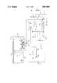
- a metal lock housing 50is shown as being electrically connected to ground.
- the housing 50is generally cylindrical in cross-section and contains an opening 52 into which a key lock assembly 40 is inserted for retention.
- the retention mechanismmay be of any conventional type and is not shown as being a part of the present invention.
- the lock assembly 40is shown as containing a key hole aperture 42 into which a conventional key may be inserted for unlocking and rotation to actuate a conventional ignition switch, as would commonly be found on an automotive vehicle.
- a resilient spring contact 124is electrically and mechanically connected to a resistor 122, as is shown extending from a molded insulating member 26. A portion of the resilient contact member 124 extends from the insulating member 26.
- the insulating member 26is positioned within an aperture 53 formed in the housing 50 and is retained therein.
- a portion of the resilient contact 124extends within the housing 50 and is formed so as to be compressed against the internal conducting wall surface of the housing 50 when the lock assembly 40 is properly inserted into the housing. In this manner, the resilient contact member 124 provides a continuous electrical ground to one side of resistor 122 as long as the lock assembly 40 is within the housing 50. Upon forced removal of the lock 40 from the housing 50, resilient member 124 will break contact with the housing 50 causing an interruption in the electrical path through the resistor 122.
- circuit 100is shown herein as providing a continuous monitoring of the condition of the lock assembly 40 when the ignition switch is turned off, it is forseen that the circuit 100 could, in the alternative, be continuously powered independent of the ignition switch.
- the circuit 100receives input power via its terminal 101 through a normally closed relay contact 14 from a battery 10.
- Ignition switch S-1is connected in parallel with a normally closed relay contact 14 and also in a conventional manner to supply vehicle power to the various loads of the vehicle when the switch S-1 is closed.
- a relay coil 12is connected between the load end of the switch S-1 and ground to become energized and thereby open the normally closed relay contact 14 when the vehicle ignition switch S-1 is closed. Therefore, when the ignition switch S-1 is open the coil 12 is deenergized and the relay contact 14 becomes closed to supply battery power to the terminal 101 of the monitoring circuit 100.
- a square wave generator 102provides a charging signal V1 that is, in this embodiment, a 12 volt peak to peak square wave having a frequency on the order of 500 Hz.
- the output of square wave generator 102is connected to a pair of integrating networks that convert the square wave signal V1 to linearly ramped signals V2 and V3 that are then fed to a comparator, comprising transistors 132 and 134.
- the reference integrating networkis made up of resistor 110, capacitor 111 and resistor 112. Resistors 110 and 112 form a voltage divider between the output terminal of the square wave generator 102 and ground.
- the capacitor 111is connected between the junction of the two resistors 110 and 112 and ground. The junction of the two resistors 110 and 112 and the capacitor 111 is connected to the base of transistor 134 and emitter of transistor 132.
- the sensing integration networkis formed by resistor 120, capacitor 121 and resistor 122, located integral with the switch 124 in the lock housing 50.
- Capacitor 121is electrically connected between the junction of resistors 120 and 122 and ground. The junction is also connected to the base of transistor 132 and the emitter of transistor 134.
- resistors 110 and 120are equal, capacitors 111 and 121 are equal and resistors 112 and 122 are equal. Therefore, as long as the electrical path of the sensing integration network is maintained, the voltages appearing at the bases of transistors 132 and 134 are equal to the voltages appearing at their emitters. As such, the transistors 132 and 134 will constantly remain in their high impedance (nonconducting) states.
- the collectors of the transistors 132 and 134are connected to the base of transistor 139 through a voltage divider network formed by resistors 136 and 138. While both transistors 132 and 134 remain in their nonconducting states, the transistor 139 is held in its high impedance state.
Landscapes
- Engineering & Computer Science (AREA)
- Mechanical Engineering (AREA)
- Burglar Alarm Systems (AREA)
Abstract
Description
Claims (3)
Priority Applications (2)
| Application Number | Priority Date | Filing Date | Title |
|---|---|---|---|
| US07/050,814US4803460A (en) | 1987-05-18 | 1987-05-18 | Anti-theft system |
| CA000567024ACA1283468C (en) | 1987-05-18 | 1988-05-17 | Anti-theft system |
Applications Claiming Priority (1)
| Application Number | Priority Date | Filing Date | Title |
|---|---|---|---|
| US07/050,814US4803460A (en) | 1987-05-18 | 1987-05-18 | Anti-theft system |
Publications (1)
| Publication Number | Publication Date |
|---|---|
| US4803460Atrue US4803460A (en) | 1989-02-07 |
Family
ID=21967601
Family Applications (1)
| Application Number | Title | Priority Date | Filing Date |
|---|---|---|---|
| US07/050,814Expired - LifetimeUS4803460A (en) | 1987-05-18 | 1987-05-18 | Anti-theft system |
Country Status (2)
| Country | Link |
|---|---|
| US (1) | US4803460A (en) |
| CA (1) | CA1283468C (en) |
Cited By (19)
| Publication number | Priority date | Publication date | Assignee | Title |
|---|---|---|---|---|
| US4866416A (en)* | 1987-10-01 | 1989-09-12 | Daimler-Benz Aktiengesellschaft | Anti-theft device for an automobile audio set |
| US5041814A (en)* | 1990-06-20 | 1991-08-20 | Lin Fu Tong E | Lock with alarm device |
| EP0582482A1 (en)* | 1992-08-05 | 1994-02-09 | Inchcape Plc | A security means |
| US5300066A (en)* | 1990-02-07 | 1994-04-05 | Coherent, Inc. | Contact laser delivery system |
| EP0618113A1 (en)* | 1993-03-30 | 1994-10-05 | Asahi Denso Kabushiki Kaisha | Antitheft device for a vehicle |
| DE4317116A1 (en)* | 1993-05-21 | 1994-11-24 | Audi Ag | Anti-theft device as an immobiliser on a motor vehicle |
| US5451925A (en)* | 1992-04-09 | 1995-09-19 | Le; Hy D. | Passive instant automatic vehicle anti-theft device |
| US5506563A (en)* | 1994-04-12 | 1996-04-09 | Jonic; Danko | Motor vehicle anti-theft security system |
| US5638944A (en)* | 1995-09-11 | 1997-06-17 | Ford Motor Company | Ignition cylinder anti-theft sensor contact mechanism |
| FR2752796A1 (en)* | 1996-09-04 | 1998-03-06 | Peugeot | Anti-theft device operating on ignition-starter circuit of motor vehicles |
| US5793122A (en)* | 1996-06-11 | 1998-08-11 | Motor Vehicle Protection Systems, Inc. | Automobile security device |
| US5887466A (en)* | 1995-11-16 | 1999-03-30 | Nissan Motor Co., Ltd. | Door lock control system with a dead lock device for an automotive vehicle |
| US6249061B1 (en)* | 1998-04-23 | 2001-06-19 | Lucas Industries Plc | Security arrangement |
| US6479908B1 (en) | 2000-04-20 | 2002-11-12 | General Motors Corporation | Apparatus and method for sensing positions of an ignition switch |
| US20060179900A1 (en)* | 2004-03-05 | 2006-08-17 | Triteq Lock And Security, L.L.C. | Vending machine lock with motor controlled slide-bar and hook mechanism and electronic access |
| US20060186678A1 (en)* | 2000-11-21 | 2006-08-24 | Triteq Lock And Security, Llc | Electronic cam locking systems for vending machines and the like |
| US20130233031A1 (en)* | 2010-06-30 | 2013-09-12 | Valeo Securite Habitacle | Disengageable lock |
| US9523215B2 (en) | 2000-11-21 | 2016-12-20 | Triteq Lock And Security, Llc | Electronic locking systems for vending machines and the like |
| US11002039B2 (en) | 2012-04-20 | 2021-05-11 | Triteq Lock And Security, L.L.C. | Electronic controlled handles |
Citations (6)
| Publication number | Priority date | Publication date | Assignee | Title |
|---|---|---|---|---|
| US3629818A (en)* | 1968-11-12 | 1971-12-21 | Nissan Motor | Antitheft device for a motor vehicle |
| US3654600A (en)* | 1969-12-29 | 1972-04-04 | Nissan Motor | Steering locking device |
| US4233595A (en)* | 1978-11-30 | 1980-11-11 | Christoph Emmerich Kg | Chain-type door latch and alarm |
| US4310835A (en)* | 1979-02-09 | 1982-01-12 | Donald Arthur Arnold | Security equipment including trigger circuit |
| US4427967A (en)* | 1981-07-14 | 1984-01-24 | Arman S.P.A. | Electronic signaling device |
| US4449605A (en)* | 1981-03-23 | 1984-05-22 | Read William A | Device for preventing theft of motor vehicles |
- 1987
- 1987-05-18USUS07/050,814patent/US4803460A/ennot_activeExpired - Lifetime
- 1988
- 1988-05-17CACA000567024Apatent/CA1283468C/ennot_activeExpired - Lifetime
Patent Citations (6)
| Publication number | Priority date | Publication date | Assignee | Title |
|---|---|---|---|---|
| US3629818A (en)* | 1968-11-12 | 1971-12-21 | Nissan Motor | Antitheft device for a motor vehicle |
| US3654600A (en)* | 1969-12-29 | 1972-04-04 | Nissan Motor | Steering locking device |
| US4233595A (en)* | 1978-11-30 | 1980-11-11 | Christoph Emmerich Kg | Chain-type door latch and alarm |
| US4310835A (en)* | 1979-02-09 | 1982-01-12 | Donald Arthur Arnold | Security equipment including trigger circuit |
| US4449605A (en)* | 1981-03-23 | 1984-05-22 | Read William A | Device for preventing theft of motor vehicles |
| US4427967A (en)* | 1981-07-14 | 1984-01-24 | Arman S.P.A. | Electronic signaling device |
Cited By (25)
| Publication number | Priority date | Publication date | Assignee | Title |
|---|---|---|---|---|
| US4866416A (en)* | 1987-10-01 | 1989-09-12 | Daimler-Benz Aktiengesellschaft | Anti-theft device for an automobile audio set |
| US5300066A (en)* | 1990-02-07 | 1994-04-05 | Coherent, Inc. | Contact laser delivery system |
| US5041814A (en)* | 1990-06-20 | 1991-08-20 | Lin Fu Tong E | Lock with alarm device |
| US5451925A (en)* | 1992-04-09 | 1995-09-19 | Le; Hy D. | Passive instant automatic vehicle anti-theft device |
| EP0582482A1 (en)* | 1992-08-05 | 1994-02-09 | Inchcape Plc | A security means |
| US5554891A (en)* | 1993-03-30 | 1996-09-10 | Asahi Denso Kabushiki Kaisha | Antitheft device for a vehicle |
| EP0618113A1 (en)* | 1993-03-30 | 1994-10-05 | Asahi Denso Kabushiki Kaisha | Antitheft device for a vehicle |
| DE4317116A1 (en)* | 1993-05-21 | 1994-11-24 | Audi Ag | Anti-theft device as an immobiliser on a motor vehicle |
| USRE36075E (en)* | 1994-04-12 | 1999-02-02 | Jonic; Danko | Motor vehicle anti-theft security system |
| US5506563A (en)* | 1994-04-12 | 1996-04-09 | Jonic; Danko | Motor vehicle anti-theft security system |
| US5638944A (en)* | 1995-09-11 | 1997-06-17 | Ford Motor Company | Ignition cylinder anti-theft sensor contact mechanism |
| US5887466A (en)* | 1995-11-16 | 1999-03-30 | Nissan Motor Co., Ltd. | Door lock control system with a dead lock device for an automotive vehicle |
| US5793122A (en)* | 1996-06-11 | 1998-08-11 | Motor Vehicle Protection Systems, Inc. | Automobile security device |
| FR2752796A1 (en)* | 1996-09-04 | 1998-03-06 | Peugeot | Anti-theft device operating on ignition-starter circuit of motor vehicles |
| US6249061B1 (en)* | 1998-04-23 | 2001-06-19 | Lucas Industries Plc | Security arrangement |
| US6479908B1 (en) | 2000-04-20 | 2002-11-12 | General Motors Corporation | Apparatus and method for sensing positions of an ignition switch |
| US20060186678A1 (en)* | 2000-11-21 | 2006-08-24 | Triteq Lock And Security, Llc | Electronic cam locking systems for vending machines and the like |
| US9260886B2 (en) | 2000-11-21 | 2016-02-16 | Triteq Lock And Security, Llc | Electronic cam locking systems for vending machines and the like |
| US9523215B2 (en) | 2000-11-21 | 2016-12-20 | Triteq Lock And Security, Llc | Electronic locking systems for vending machines and the like |
| US20060179900A1 (en)* | 2004-03-05 | 2006-08-17 | Triteq Lock And Security, L.L.C. | Vending machine lock with motor controlled slide-bar and hook mechanism and electronic access |
| US20150069765A1 (en)* | 2004-03-05 | 2015-03-12 | Triteq Lock And Security, L.L.C. | Vending Machine Lock with Motor Controlled Slide-Bar and Hook Mechanism and Electronic Access |
| US10174522B2 (en)* | 2004-03-05 | 2019-01-08 | Triteq Lock And Security, L.L.C. | Vending machine lock with motor controlled slide-bar and hook mechanism and electronic access |
| US20130233031A1 (en)* | 2010-06-30 | 2013-09-12 | Valeo Securite Habitacle | Disengageable lock |
| US9133648B2 (en)* | 2010-06-30 | 2015-09-15 | U-Shin France Sas | Disengageable lock |
| US11002039B2 (en) | 2012-04-20 | 2021-05-11 | Triteq Lock And Security, L.L.C. | Electronic controlled handles |
Also Published As
| Publication number | Publication date |
|---|---|
| CA1283468C (en) | 1991-04-23 |
Similar Documents
| Publication | Publication Date | Title |
|---|---|---|
| US4803460A (en) | Anti-theft system | |
| US4148372A (en) | Resistor coded theft deterrent system | |
| US5191228A (en) | Vehicle battery disconnect antitheft device | |
| US5170151A (en) | Method and assembly for disconnecting a battery from its operating system | |
| US5552642A (en) | Protection system with voltage switching | |
| US4584569A (en) | Motion sensitive security system | |
| US4546266A (en) | Magnetically actuated interlock | |
| US5506563A (en) | Motor vehicle anti-theft security system | |
| US4063610A (en) | Vehicle theft-prevention system | |
| US4485887A (en) | Vehicular anti-theft device | |
| US4296402A (en) | Vehicle anti-theft device | |
| US5498486A (en) | Security batteries for automotive vehicles | |
| US3878507A (en) | Sensor device and alarm circuit for fuel tanks | |
| US4037194A (en) | Current sensing alarm circuit for a motor vehicle | |
| US4857888A (en) | Automotive alarm | |
| US3569929A (en) | Transient voltage detector burglar alarm system for vehicles | |
| US3634844A (en) | Tamperproof alarm construction | |
| EP0767541A3 (en) | Car radio with electronic theft protection | |
| US3831141A (en) | Alarm circuit | |
| JPS62255261A (en) | Burglar alarm device for vehicle | |
| US4013995A (en) | Vehicle burglar alarm | |
| US3794967A (en) | Intruder alarm for automobiles | |
| US3643214A (en) | Solid-state burglar alarm system for automobile | |
| US3967166A (en) | Electronic lock | |
| US4297674A (en) | Passive security device |
Legal Events
| Date | Code | Title | Description |
|---|---|---|---|
| AS | Assignment | Owner name:FORD MOTOR COMPANY, THE, DEARBORN, MICHIGAN, A COR Free format text:ASSIGNMENT OF ASSIGNORS INTEREST.;ASSIGNORS:RHEE, DENNIS W.;FLETCHER, SIDNEY R.;REEL/FRAME:004763/0609 Effective date:19870512 Owner name:FORD MOTOR COMPANY, THE,MICHIGAN Free format text:ASSIGNMENT OF ASSIGNORS INTEREST;ASSIGNORS:RHEE, DENNIS W.;FLETCHER, SIDNEY R.;REEL/FRAME:004763/0609 Effective date:19870512 | |
| STCF | Information on status: patent grant | Free format text:PATENTED CASE | |
| FEPP | Fee payment procedure | Free format text:PAYOR NUMBER ASSIGNED (ORIGINAL EVENT CODE: ASPN); ENTITY STATUS OF PATENT OWNER: LARGE ENTITY | |
| FPAY | Fee payment | Year of fee payment:4 | |
| FPAY | Fee payment | Year of fee payment:8 | |
| AS | Assignment | Owner name:VISTEON GLOBAL TECHNOLOGIES, INC., MICHIGAN Free format text:ASSIGNMENT OF ASSIGNORS INTEREST;ASSIGNOR:FORD MOTOR COMPANY;REEL/FRAME:010968/0220 Effective date:20000615 | |
| FPAY | Fee payment | Year of fee payment:12 | |
| AS | Assignment | Owner name:JPMORGAN CHASE BANK, N.A., AS ADMINISTRATIVE AGENT Free format text:SECURITY AGREEMENT;ASSIGNOR:VISTEON GLOBAL TECHNOLOGIES, INC.;REEL/FRAME:020497/0733 Effective date:20060613 | |
| AS | Assignment | Owner name:JPMORGAN CHASE BANK, TEXAS Free format text:SECURITY INTEREST;ASSIGNOR:VISTEON GLOBAL TECHNOLOGIES, INC.;REEL/FRAME:022368/0001 Effective date:20060814 Owner name:JPMORGAN CHASE BANK,TEXAS Free format text:SECURITY INTEREST;ASSIGNOR:VISTEON GLOBAL TECHNOLOGIES, INC.;REEL/FRAME:022368/0001 Effective date:20060814 | |
| AS | Assignment | Owner name:WILMINGTON TRUST FSB, AS ADMINISTRATIVE AGENT, MIN Free format text:ASSIGNMENT OF SECURITY INTEREST IN PATENTS;ASSIGNOR:JPMORGAN CHASE BANK, N.A., AS ADMINISTRATIVE AGENT;REEL/FRAME:022575/0186 Effective date:20090415 Owner name:WILMINGTON TRUST FSB, AS ADMINISTRATIVE AGENT,MINN Free format text:ASSIGNMENT OF SECURITY INTEREST IN PATENTS;ASSIGNOR:JPMORGAN CHASE BANK, N.A., AS ADMINISTRATIVE AGENT;REEL/FRAME:022575/0186 Effective date:20090415 | |
| AS | Assignment | Owner name:VISTEON GLOBAL TECHNOLOGIES, INC., MICHIGAN Free format text:RELEASE BY SECURED PARTY AGAINST SECURITY INTEREST IN PATENTS RECORDED AT REEL 022575 FRAME 0186;ASSIGNOR:WILMINGTON TRUST FSB, AS ADMINISTRATIVE AGENT;REEL/FRAME:025105/0201 Effective date:20101001 |