US4802852A - Irrigated drill and quick-release chuck assembly - Google Patents
Irrigated drill and quick-release chuck assemblyDownload PDFInfo
- Publication number
- US4802852A US4802852AUS06/917,669US91766986AUS4802852AUS 4802852 AUS4802852 AUS 4802852AUS 91766986 AUS91766986 AUS 91766986AUS 4802852 AUS4802852 AUS 4802852A
- Authority
- US
- United States
- Prior art keywords
- bur
- shank
- bearing
- sleeve
- drill
- Prior art date
- Legal status (The legal status is an assumption and is not a legal conclusion. Google has not performed a legal analysis and makes no representation as to the accuracy of the status listed.)
- Expired - Fee Related
Links
Images

Classifications
- A—HUMAN NECESSITIES
- A61—MEDICAL OR VETERINARY SCIENCE; HYGIENE
- A61C—DENTISTRY; APPARATUS OR METHODS FOR ORAL OR DENTAL HYGIENE
- A61C1/00—Dental machines for boring or cutting ; General features of dental machines or apparatus, e.g. hand-piece design
- A61C1/02—Dental machines for boring or cutting ; General features of dental machines or apparatus, e.g. hand-piece design characterised by the drive of the dental tools
- A61C1/05—Dental machines for boring or cutting ; General features of dental machines or apparatus, e.g. hand-piece design characterised by the drive of the dental tools with turbine drive
- A61C1/052—Ducts for supplying driving or cooling fluid, e.g. air, water
- A—HUMAN NECESSITIES
- A61—MEDICAL OR VETERINARY SCIENCE; HYGIENE
- A61C—DENTISTRY; APPARATUS OR METHODS FOR ORAL OR DENTAL HYGIENE
- A61C1/00—Dental machines for boring or cutting ; General features of dental machines or apparatus, e.g. hand-piece design
- A61C1/08—Machine parts specially adapted for dentistry
- A61C1/14—Tool-holders, i.e. operating tool holders, e.g. burr holders
Definitions
- the primary object of this inventionis to provide a high speed, electric motor driven drill having an irrigation system for squirting water onto a bur while simultaneously cooling the motor, plus a quick-release, quick-engaging chuck assembly for engaging and firmly holding in place a bur shank.
- the drill of this inventionhas particular utility in performing certain operations where extremely high speed and vibration-free rotation of a bur is needed and where water is squirted onto the bur so as to irrigate it during its cutting operations.
- a further objectis to provide a chuck into which a bur shank is drivingly engaged, and which locks the bur shank in so that only minor manipulation, i.e., a slight rotative movement at most is needed to insert the bur shank and which releases the bur shank in response to only a very short pressing-in of a plunger
- the bur shank used in this chuckhas a flat end which drivingly engages in a slot in the motor drive shaft, and near the flat end is a annular groove in this bur shank, into which the inner race of the ball bearing engages so as to block outward movement of the bur shank until the inner race of the ball bearing is removed from its blocking position.
- FIG. 1is a perspective view of the drill with the bur installed
- FIG. 2is a cross sectional view of the casing with the inner part shown in side elevation;
- FIG. 3is a side elevation of the motor cooling and irrigation tube removed from the assembly
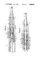
- FIG. 4is a longitudinal cross section of the forward part of the assembly with the bur blocked in;
- FIG. 5is a view similar to FIG. 4 but with the bur shank unlocked
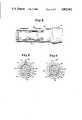
- FIG. 6is a planned view of the inner side of the housing showing the spring-accommodating grooves
- FIG. 7is a transverse cross section along the line 77 of FIG. 4;
- FIG. 8is a transverse cross section along the line 88 of FIG. 5.
- the drill 2is enclosed within a housing 4 having an enlargement 6 at its rear end for accommodating a motor 8 having a generally cylindrical outer surface portion 9.
- a nose cone 10from which normally projects the shank 12 of a bur 13.
- an electrical supply cord 14Leading from the rear end of the housing are an electrical supply cord 14 and an irrigation tube 16 which is coupled as 18 to a water supply tube 20.
- the water supply tube 20has convolutions 22 which surround the cylindrical outer surface portion and cool the motor when water passes through the irrigation tube.
- the tubehas an off-set 23 so as to permit it to pass around the chuck assembly 34 when it, the tube, is inserted from the rear of the housing.
- the motor 8has a drive shaft 24 which extends forwardly through the hollow interior of housing 4.
- the forward portion of the drive shaftis connected by a pin 26 to a sleeve 28 which is rotatably supported in the housing by a bearing 30.
- Bearing 30is mounted in the rear end of the nose cone by press fit as indicated at 32.
- the chuck assembly 34is as follows:
- a cross slot 36into which a flat end 38 of bur shank 12 engages.
- the forward end of the bur shankis rotatably supported in the nose cone by bearings 40 and 42 so that the bur shank rotates about a fixed axis without vibration or rattling.
- a seal 44is held in place by a collar 46 threaded as at 48 into the nose cone.
- the nose conemay be secured to the housing by one or more set screws 50, although there are other known mechanical means for doing this.
- the sleeve 52At the heart of the chuck assembly is the sleeve 52 which has slight freedom of transverse movement with respect to the bur shank as well as the fixed elements of the housing and its nose cone.
- sleeve 52Supported in sleeve 52 is a bearing 54 which is held in place by a nut 56 threaded as at 58 into the sleeve.
- a bearing 54Near the rear of bur shank 12 is an annular groove 60 into which the inner race of bearing 54 may engage so as to block the bur shank 12 against outward movement.
- Sleeve 52is biased by leaf springs 62, 64 so that the inner race of bearing 54 normally engages in the annular groove 60 in the bur shank when the groove 60 is brought into registry with the bearing race.
- sleeve 52is moved downwardly (as seen in the drawings) by depressing a plunger 68 which is threaded as at 70 in sleeve 52 and freely passes through openings 72 in the housing and nose cone.
- the tapered shoulder 74 at the inner ends of the flatspermit the bur shank to crowd its way to the inner race of bearing 54 and move into place, as seen in FIG. 4, with slight rotary manipulation, if needed, to bring the flat end of the bur shank into registry with the cross slot 36 in the end of the motor drive shaft.
- leaf springs 62, 64force sleeve 52 towards bur shank 12 so that the bearing 52 snaps in place into annular groove 60, thereby blocking outward movement of the bur shank.
- plunger 68When it is desired to remove the bur, plunger 68 is depressed so as to move sleeve 52 downwardly, as seen in FIGS. 4 and 5, thereby clearing the bearing 54 from the annular groove 60. This permits the bur to be removed. It should be noted that only slight depression of plunger 68 is needed to move the bearing 54 from its blocking position (FIG. 4) to its unblocking position (FIG. 5).
Landscapes
- Health & Medical Sciences (AREA)
- Oral & Maxillofacial Surgery (AREA)
- Dentistry (AREA)
- Epidemiology (AREA)
- Life Sciences & Earth Sciences (AREA)
- Animal Behavior & Ethology (AREA)
- General Health & Medical Sciences (AREA)
- Public Health (AREA)
- Veterinary Medicine (AREA)
- Surgical Instruments (AREA)
Abstract
Description
Claims (3)
Priority Applications (1)
| Application Number | Priority Date | Filing Date | Title |
|---|---|---|---|
| US06/917,669US4802852A (en) | 1986-10-10 | 1986-10-10 | Irrigated drill and quick-release chuck assembly |
Applications Claiming Priority (1)
| Application Number | Priority Date | Filing Date | Title |
|---|---|---|---|
| US06/917,669US4802852A (en) | 1986-10-10 | 1986-10-10 | Irrigated drill and quick-release chuck assembly |
Publications (1)
| Publication Number | Publication Date |
|---|---|
| US4802852Atrue US4802852A (en) | 1989-02-07 |
Family
ID=25439161
Family Applications (1)
| Application Number | Title | Priority Date | Filing Date |
|---|---|---|---|
| US06/917,669Expired - Fee RelatedUS4802852A (en) | 1986-10-10 | 1986-10-10 | Irrigated drill and quick-release chuck assembly |
Country Status (1)
| Country | Link |
|---|---|
| US (1) | US4802852A (en) |
Cited By (11)
| Publication number | Priority date | Publication date | Assignee | Title |
|---|---|---|---|---|
| US5312349A (en)* | 1991-11-25 | 1994-05-17 | Kaltenbach & Voigt Gmbh & Co. | Medical treatment device, in particular for surgical purposes |
| US5352118A (en)* | 1991-12-19 | 1994-10-04 | Siemens Aktiengesellschaft | Dental instrument having a nozzle for cooling |
| WO1996010369A1 (en)* | 1994-09-30 | 1996-04-11 | Young Dental Manufacturing Company, Inc. | Dental tool chuck |
| US5718582A (en)* | 1995-09-26 | 1998-02-17 | Young Dental Manufacturing | Dental tool chuck |
| US6171300B1 (en) | 1997-09-04 | 2001-01-09 | Linvatec Corporation | Tubing cassette and method for cooling a surgical handpiece |
| WO2002024083A3 (en)* | 2000-09-24 | 2002-06-13 | Medtronic Inc | Liquid cooled, powered surgical handpiece |
| US20070021752A1 (en)* | 2005-07-25 | 2007-01-25 | Rogers William G | Motorized surgical handpiece |
| US20070296286A1 (en)* | 2003-10-28 | 2007-12-27 | Avenell Eric G | Powered Hand Tool |
| US20080299514A1 (en)* | 2006-05-03 | 2008-12-04 | Bien-Air Holding Sa | Hand-Held Instrument for Dental or Surgical Use |
| CN110170681A (en)* | 2019-06-06 | 2019-08-27 | 深圳市瑞沃德生命科技有限公司 | A kind of mini small electric drill |
| US11413051B2 (en) | 2017-07-25 | 2022-08-16 | Stryker European Holdings I Llc | Irrigation sleeves for use with surgical systems |
Citations (5)
| Publication number | Priority date | Publication date | Assignee | Title |
|---|---|---|---|---|
| US233709A (en)* | 1880-10-26 | starr | ||
| US2536017A (en)* | 1947-04-22 | 1951-01-02 | Speedo Mfg Co Inc | Rotary tool hand piece |
| US3631597A (en)* | 1969-09-15 | 1972-01-04 | Star Dental Mfg Co | Handpiece with improved chuck assembly |
| US4184256A (en)* | 1977-12-12 | 1980-01-22 | Kaltenbach & Voigt Gmbh & Co. | Miniature motor having an internal coolant line |
| US4568283A (en)* | 1983-10-24 | 1986-02-04 | Kabushiki Kaisha Morita Seisaksuho | Medical handpiece |
- 1986
- 1986-10-10USUS06/917,669patent/US4802852A/ennot_activeExpired - Fee Related
Patent Citations (5)
| Publication number | Priority date | Publication date | Assignee | Title |
|---|---|---|---|---|
| US233709A (en)* | 1880-10-26 | starr | ||
| US2536017A (en)* | 1947-04-22 | 1951-01-02 | Speedo Mfg Co Inc | Rotary tool hand piece |
| US3631597A (en)* | 1969-09-15 | 1972-01-04 | Star Dental Mfg Co | Handpiece with improved chuck assembly |
| US4184256A (en)* | 1977-12-12 | 1980-01-22 | Kaltenbach & Voigt Gmbh & Co. | Miniature motor having an internal coolant line |
| US4568283A (en)* | 1983-10-24 | 1986-02-04 | Kabushiki Kaisha Morita Seisaksuho | Medical handpiece |
Cited By (19)
| Publication number | Priority date | Publication date | Assignee | Title |
|---|---|---|---|---|
| US5312349A (en)* | 1991-11-25 | 1994-05-17 | Kaltenbach & Voigt Gmbh & Co. | Medical treatment device, in particular for surgical purposes |
| US5352118A (en)* | 1991-12-19 | 1994-10-04 | Siemens Aktiengesellschaft | Dental instrument having a nozzle for cooling |
| WO1996010369A1 (en)* | 1994-09-30 | 1996-04-11 | Young Dental Manufacturing Company, Inc. | Dental tool chuck |
| US5718582A (en)* | 1995-09-26 | 1998-02-17 | Young Dental Manufacturing | Dental tool chuck |
| US6171300B1 (en) | 1997-09-04 | 2001-01-09 | Linvatec Corporation | Tubing cassette and method for cooling a surgical handpiece |
| JP2012166035A (en)* | 2000-09-24 | 2012-09-06 | Medtronic Inc | Liquid cooled, powered surgical handpiece |
| WO2002024083A3 (en)* | 2000-09-24 | 2002-06-13 | Medtronic Inc | Liquid cooled, powered surgical handpiece |
| US6635067B2 (en) | 2000-09-24 | 2003-10-21 | Medtronic, Inc. | Liquid cooled, powered surgical handpiece |
| JP2004509673A (en)* | 2000-09-24 | 2004-04-02 | メドトロニック・インコーポレーテッド | Liquid-cooled power-operated surgical handpiece |
| JP2014193391A (en)* | 2000-09-24 | 2014-10-09 | Medtronic Inc | Liquid cooled, powered surgical handpiece |
| US20070296286A1 (en)* | 2003-10-28 | 2007-12-27 | Avenell Eric G | Powered Hand Tool |
| US20070021752A1 (en)* | 2005-07-25 | 2007-01-25 | Rogers William G | Motorized surgical handpiece |
| US7597699B2 (en) | 2005-07-25 | 2009-10-06 | Rogers William G | Motorized surgical handpiece |
| US8104774B2 (en)* | 2006-05-03 | 2012-01-31 | Bien-Air Holding Sa | Hand-held instrument for dental or surgical use |
| US20080299514A1 (en)* | 2006-05-03 | 2008-12-04 | Bien-Air Holding Sa | Hand-Held Instrument for Dental or Surgical Use |
| US11413051B2 (en) | 2017-07-25 | 2022-08-16 | Stryker European Holdings I Llc | Irrigation sleeves for use with surgical systems |
| US12121242B2 (en) | 2017-07-25 | 2024-10-22 | Stryker European Operations Holdings Llc | Surgical instrument system and irrigation sleeve |
| CN110170681A (en)* | 2019-06-06 | 2019-08-27 | 深圳市瑞沃德生命科技有限公司 | A kind of mini small electric drill |
| CN110170681B (en)* | 2019-06-06 | 2021-07-09 | 深圳市瑞沃德生命科技有限公司 | Mini electric drill |
Similar Documents
| Publication | Publication Date | Title |
|---|---|---|
| US4802852A (en) | Irrigated drill and quick-release chuck assembly | |
| US5398946A (en) | Chuck having one-step lock and release | |
| US5609603A (en) | Surgical cutting device with safety interlock | |
| US4289131A (en) | Surgical power tool | |
| US7374377B2 (en) | Bit holding apparatus for use with a power tool | |
| US6000940A (en) | Surgical bur shank and locking collet mechanism | |
| US3975032A (en) | Surgical wire driving assembly | |
| US7597699B2 (en) | Motorized surgical handpiece | |
| US4007528A (en) | High speed bone drill | |
| US20040059317A1 (en) | Drilling tool for a surgical drill | |
| US6139228A (en) | Keyless chuck assembly for a rotary driven tool | |
| US4834596A (en) | Quick change spindle adaptor for tool holder | |
| KR940010892B1 (en) | Hole saw | |
| JPH1071515A (en) | Drilling device | |
| BRPI1007756B1 (en) | QUICK RELEASE CONNECTOR FOR A POWER TOOL ACCESSORY | |
| US4762035A (en) | Depth adjusting device for screwdrivers | |
| WO2003011533B1 (en) | Battery powered screwdriver and screw starting device | |
| US4811736A (en) | Surgical drill and bur for use therewith | |
| US5190422A (en) | Device for the quick fastening of a tool intended to be driven in rotation | |
| EP0691184B1 (en) | Collet type fastener removal tool | |
| US4055185A (en) | Rotary drill for surgeons | |
| JP2008044101A (en) | System, method and apparatus for drill bit alignment and depth control with an ergonomic drill motor | |
| GB1575585A (en) | Spindle and draw bar assembly | |
| US3400459A (en) | Dental handpiece | |
| GB1418109A (en) | Handpiece assembly for supporting a rotatable tool |
Legal Events
| Date | Code | Title | Description |
|---|---|---|---|
| AS | Assignment | Owner name:RICHARDS MEDICAL COMPANY, 1450 BROOKS ROAD, MEMPHI Free format text:ASSIGNMENT OF ASSIGNORS INTEREST.;ASSIGNOR:SHEA, JOHN J.;REEL/FRAME:004830/0065 Effective date:19871210 Owner name:RICHARDS MEDICAL COMPANY, A CORP. OF DE,TENNESSEE Free format text:ASSIGNMENT OF ASSIGNORS INTEREST;ASSIGNOR:SHEA, JOHN J.;REEL/FRAME:004830/0065 Effective date:19871210 Owner name:RICHARDS MEDICAL COMPANY, TENNESSEE Free format text:ASSIGNMENT OF ASSIGNORS INTEREST;ASSIGNOR:SHEA, JOHN J.;REEL/FRAME:004830/0065 Effective date:19871210 | |
| FEPP | Fee payment procedure | Free format text:PAYOR NUMBER ASSIGNED (ORIGINAL EVENT CODE: ASPN); ENTITY STATUS OF PATENT OWNER: LARGE ENTITY | |
| FPAY | Fee payment | Year of fee payment:4 | |
| REMI | Maintenance fee reminder mailed | ||
| LAPS | Lapse for failure to pay maintenance fees | ||
| FP | Lapsed due to failure to pay maintenance fee | Effective date:19970212 | |
| STCH | Information on status: patent discontinuation | Free format text:PATENT EXPIRED DUE TO NONPAYMENT OF MAINTENANCE FEES UNDER 37 CFR 1.362 |