US4802353A - Battery-powered door lock assembly and method - Google Patents
Battery-powered door lock assembly and methodDownload PDFInfo
- Publication number
- US4802353A US4802353AUS07/083,668US8366887AUS4802353AUS 4802353 AUS4802353 AUS 4802353AUS 8366887 AUS8366887 AUS 8366887AUS 4802353 AUS4802353 AUS 4802353A
- Authority
- US
- United States
- Prior art keywords
- movement
- handle
- lock assembly
- bolt
- locking
- Prior art date
- Legal status (The legal status is an assumption and is not a legal conclusion. Google has not performed a legal analysis and makes no representation as to the accuracy of the status listed.)
- Expired - Lifetime
Links
- 238000000034methodMethods0.000titleclaimsdescription8
- 230000004044responseEffects0.000claimsabstractdescription8
- 230000008878couplingEffects0.000claimsdescription10
- 238000010168coupling processMethods0.000claimsdescription10
- 238000005859coupling reactionMethods0.000claimsdescription10
- 230000006872improvementEffects0.000claimsdescription3
- 238000006073displacement reactionMethods0.000claimsdescription2
- 230000007246mechanismEffects0.000description9
- 238000013459approachMethods0.000description6
- 210000003813thumbAnatomy0.000description6
- 238000010276constructionMethods0.000description5
- 239000003990capacitorSubstances0.000description4
- 230000000712assemblyEffects0.000description3
- 238000000429assemblyMethods0.000description3
- 239000004020conductorSubstances0.000description3
- 230000000694effectsEffects0.000description2
- 239000003302ferromagnetic materialSubstances0.000description2
- 230000005291magnetic effectEffects0.000description2
- 230000003213activating effectEffects0.000description1
- 230000008901benefitEffects0.000description1
- 230000008859changeEffects0.000description1
- 230000007797corrosionEffects0.000description1
- 238000005260corrosionMethods0.000description1
- 230000000994depressogenic effectEffects0.000description1
- 230000009977dual effectEffects0.000description1
- 230000006870functionEffects0.000description1
- 230000005484gravityEffects0.000description1
- 238000004519manufacturing processMethods0.000description1
- 239000000463materialSubstances0.000description1
- 230000013011matingEffects0.000description1
- 238000005192partitionMethods0.000description1
- 238000003825pressingMethods0.000description1
- 230000008569processEffects0.000description1
- 230000035939shockEffects0.000description1
- 230000000007visual effectEffects0.000description1
Images


Classifications
- E—FIXED CONSTRUCTIONS
- E05—LOCKS; KEYS; WINDOW OR DOOR FITTINGS; SAFES
- E05B—LOCKS; ACCESSORIES THEREFOR; HANDCUFFS
- E05B47/00—Operating or controlling locks or other fastening devices by electric or magnetic means
- E05B47/06—Controlling mechanically-operated bolts by electro-magnetically-operated detents
- E05B47/0657—Controlling mechanically-operated bolts by electro-magnetically-operated detents by locking the handle, spindle, follower or the like
- E05B47/0661—Controlling mechanically-operated bolts by electro-magnetically-operated detents by locking the handle, spindle, follower or the like axially, i.e. with an axially engaging blocking element
- E—FIXED CONSTRUCTIONS
- E05—LOCKS; KEYS; WINDOW OR DOOR FITTINGS; SAFES
- E05B—LOCKS; ACCESSORIES THEREFOR; HANDCUFFS
- E05B47/00—Operating or controlling locks or other fastening devices by electric or magnetic means
- E05B2047/0048—Circuits, feeding, monitoring
- E05B2047/0057—Feeding
- E05B2047/0058—Feeding by batteries
- E—FIXED CONSTRUCTIONS
- E05—LOCKS; KEYS; WINDOW OR DOOR FITTINGS; SAFES
- E05B—LOCKS; ACCESSORIES THEREFOR; HANDCUFFS
- E05B47/00—Operating or controlling locks or other fastening devices by electric or magnetic means
- E05B2047/0048—Circuits, feeding, monitoring
- E05B2047/0065—Saving energy
- E—FIXED CONSTRUCTIONS
- E05—LOCKS; KEYS; WINDOW OR DOOR FITTINGS; SAFES
- E05B—LOCKS; ACCESSORIES THEREFOR; HANDCUFFS
- E05B47/00—Operating or controlling locks or other fastening devices by electric or magnetic means
- E05B47/0001—Operating or controlling locks or other fastening devices by electric or magnetic means with electric actuators; Constructional features thereof
- E05B47/0002—Operating or controlling locks or other fastening devices by electric or magnetic means with electric actuators; Constructional features thereof with electromagnets
- E05B47/0006—Operating or controlling locks or other fastening devices by electric or magnetic means with electric actuators; Constructional features thereof with electromagnets having a non-movable core; with permanent magnet
- Y—GENERAL TAGGING OF NEW TECHNOLOGICAL DEVELOPMENTS; GENERAL TAGGING OF CROSS-SECTIONAL TECHNOLOGIES SPANNING OVER SEVERAL SECTIONS OF THE IPC; TECHNICAL SUBJECTS COVERED BY FORMER USPC CROSS-REFERENCE ART COLLECTIONS [XRACs] AND DIGESTS
- Y10—TECHNICAL SUBJECTS COVERED BY FORMER USPC
- Y10T—TECHNICAL SUBJECTS COVERED BY FORMER US CLASSIFICATION
- Y10T70/00—Locks
- Y10T70/70—Operating mechanism
- Y10T70/7051—Using a powered device [e.g., motor]
- Y10T70/7062—Electrical type [e.g., solenoid]
Definitions
- the door lock assembly of the present inventionrelates, in general to electrically powered door lock assemblies, and more particularly, relates to keyless, digital electronic door locks which employ an electromagnet to unlock the lock mechanism.
- Capacitor-based lockshave the disadvantage that they cannot be operated unless they are given sufficient time to recharge the capacitor. Moreover, maintaining the charge on the capacitor results in wasted energy that will shorten battery life.
- Electromechanical lockswhich depend upon electrical power to move the bolt, or to move a lock releasing element, inherently face the problem that the mechanical parts can require significant energy to move. Thus, wear from general use, corrosion and shock from door slams can all result in binding or poor operation of the movable mechanical parts. Accordingly, the approach which is most suitable for a battery-powered lock assembly is for the user to manually move the movable mechanical elements in the assembly through manipulation of the door handle.
- U.S. Pat. No. 4,457,148 to Johansson, et al.is typical of a structure employing an electromagnet assembly that is energized based upon a coded input.
- the usercan manipulate the door handle to accomplish all three of: digital input to the electromagnet for energization of the same, closing of the armature in the electromagnet and movement of the locking member therewith, and movement of the bolt mechanism between the locked and unlocked position.
- the electromagnet poweris employed solely to hold the locking element in a position which releases the bolt for movement. Power is not consumed to move the armature or to move the bolt.
- Another object of the present inventionis to provide a keyless, electromechanical door lock assembly in which the movable armature of the electromagnet is held in a normally closed position eliminating the need to move the armature during opening of the lock.
- a further object of the present inventionis to provide a battery-powered lock assembly and method which is easier to use, can be opened by rotation of the door handle in either direction, is secure against attempts to open the lock without the proper combination input, is economical to manufacture and minimizes the electrical power required for operation.
- Still another object of the present inventionis to provide a battery-powered keyless electronic door lock assembly having an improved digital input means for energization of the electromagnet therein.
- the battery-powered lock assembly and method of the present inventionhave other objects and features of advantage which will become apparent from and are set forth in more detail in the accompanying drawing and following description of the Best Mode Of Carrying Out The Invention.
- the door bolt assembly of the present inventionincludes a movable bolt, a movable handle coupled to move the bolt to an open position, and a locking assembly mounted for movement between a locked position securing the bolt against movement and an unlocked position releasing the bolt for movement.
- the improvement in the lock assemblycomprises, briefly, the locking assembly being supported in the unlocked position and moving to the locked position upon movement of the handle prior to movement of the bolt to the open position.
- the bolt assemblyincludes electromagnet means responsive to an input signal for energization and positioned to hold the locking assembly in the unlocked position upon energization thereof to prevent moving of the locking assembly to the locked position upon movement of the handle.
- the locking assemblyincludes a pivotally mounted arm carrying the electromagnet armature which is held by a cam surface so that the armature is normally in contact with a solenoid portion of the electromagnet.
- the armis biased for movement away from contact and is coupled to the handle so that movement of the handle immediately causes the armature to fall away from the solenoid and the arm into a position locking the bolt against movement, unless the solenoid is energized.
- movement of the handle and opening of a boltcan be readily accomplished. Since the armature is already in contact with the solenoid, handle manipulation is not required to close the air gap. Instead, handle manipulation when the solenoid is not energized immediately locks the bolt before the handle can move the bolt to the open position.
- FIG. 1is a side elevation view, in cross-section, of a battery-powered lock assembly constructed in accordance with the present invention.
- FIG. 2is an end elevation view internal components of the lock assembly of FIG. 1 with the housing cover removed.
- FIG. 3is an end elevation view of a schematic representation of a handle spindle and locking assembly the present invention.
- FIG. 4is a schematic representation corresponding to FIG. 3 of an alternative embodiment of the handle and locking assembly of the present invention.
- FIG. 5is an enlarged, side elevation view, in cross-section of the lock assembly of FIG. 1 with certain components removed for clarity and the armature in a normally closed position.
- FIG. 6is a side elevation view corresponding to FIG. 5 with the armature in an open position.
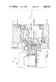
- FIG. 7is a side elevation view corresponding to FIG. 5 with the components omitted from FIGS. 5 and 6 shown.
- FIG. 8is an end elevation view taken substantially along the plane of line 8--8 in FIG. 5.
- FIG. 9is an end elevation view taken substantially along the plane of line 9--9 in FIG. 7.
- FIG. 10is an end elevation view taken substantially along the plane of line 10--10 in FIG. 7.
- FIG. 11an end elevation view taken substantially along the plane of line 11--11 in FIG. 7.
- the battery-powered door lock assembly of the present inventionemploys the basic digital electronic system as set forth in U.S. Pat. No. 4,457,148 to Johansson, et al., and such electronics are not regarded as a novel portion of the present invention.
- the present lock assemblyhas an improved mechanical structure.
- the present lock assemblyis mounted to a door or similar partition 22 with a movable handle 23 on an exterior side 24 of the door.
- a second handle 27Mounted on interior side 26 of door 22 is a second handle 27.
- Handles 26 and 27are coupled to move bolt means 28 (shown in phantom) to an open position.
- the door lock assembly of the present inventionis most preferably used in connection with a bolt 28 which is spring biased to an extended or bolted position. Handles 23 and 27, therefore, move bolt 28 from the bolted, extended position to a retracted, open position.
- the construction and spring biasing of bolt 28are not regarded as a novel portion of the assembly of the present invention.
- lock assembly 21further includes locking means, generally designated 29 (FIGS. 5 through 7), formed for movement between a locked position, which secures bolt 28 against movement from the bolted position, and an unlocked position, which releases bolt 28 for movement from the bolted position to an unbolted or retracted position.
- Lock assembly 29is coupled for movement in response to both handles 23 and 27 so that manipulation of the handles by the user, not battery powered, is employed to move bolt 28.
- electromagnet means 31(FIGS. 5-7), which may be energized by a digital, combination input as will be described hereinafter.
- electromagnet means 31cooperates with locking assembly 29 to enable unlocking of the lock when the electromagnet is energized.
- Lock assembly 21is provided with a control housing 32 on interior side 26 of the door in which the digital logic circuitry for the lock is housed on circuit board 33. Also mounted in housing 32 are batteries 34 used to power the system and other components which will be set forth hereinafter.
- the door lock assembly of the present inventiondiffers from prior electronic door locks in that locking mechanism 29 is normally supported as shown in FIG. 5 in an unlocked position, i.e., if locking mechanism 29 is maintained in the position of FIG. 5 while handle 23 is rotated, the bolt would be retracted to the open or unbolted position. It also will be seen from FIG. 5 that the armature 36 of electromagnet 31 is in contact with core 37 of the solenoid 38 portion of the electromagnet. Upon movement of lock assembly 29 as a result of rotation of handle 23 when lock assembly 29 is not held in the position of FIG. 5, however, the lock assembly immediately assumes the position shown in FIG. 6. Thus, the lugs or followers 39 of lock assembly 29 move from the position of FIG. 5 to the position of FIG. 6 and they engage stops or shoulders 41 which prevent further movement of handle 23 and bolt 28 to an open position. As will also be noted, armature 36 is out of contact with electromagnet core 37 in FIG. 6.
- handle 23ahas associated therewith a locking mechanism which includes a bar or follower 39a.
- the follower 39ais free for movement if handle 23a is rotated in either direction as indicated by arrows 42 and 43.
- the handleis not initially locked against movement to an open position.
- follower or locking bar 39awill drop into one of notches 46 and 47 and then abut against a shoulder or stop 41, which will limit further rotation of handle 23a.
- the locking bar 39amoves to a locked position prior to movement of the bolt by the handle to an open position. If the upper end 48 of bar 39a carries an electromagnet armature (not shown) and is in contact with a solenoid (not shown), energization of the solenoid will hold bar 39a against gravity biasing when handle 23a is rotated in either direction. Instead of falling into one of notches 46 and 47, bar 39a will clear shoulder 41 and the handle can be rotated until the bolt is fully retracted.
- the lock assembly of the present inventionemploys a construction in which substantially the schematic approach of FIG. 3 has been implemented.
- the lock assemblyhas been made very compact and suitable for use with many conventional lock assembly components.
- Bolt locking assembly 29includes a pivotally mounted arm in the form of yoke member 56 having a pair of legs 57 and 58 which extend upwardly from pivotal mounting pins 59 around handle spindle 61.
- the pivot pins 59can be seen in FIG. 8 while the plan view of yoke 56 is best seen in FIG. 9.
- Carried on the upper ends of legs 57 and 58is armature 36 of electromagnet means 31.
- the armatureis preferably held by a retainer spring 62 which biases armature 36 toward the upward projection 63 on the arms and yet allows armature 36 to be displaced away from projection 63 by a small distance, for example, 0.030 to 0.040 inches, upon engagement of the armature with solenoid core 37.
- Thisis an important feature of the mounting of the armature of the present invention since it permits overtravel which insures contact between armature 36 and core 37, which in turn maximizes the magnetic bond between the two.
- armature 36is formed of a ferromagnetic material, and it is preferable that the remainder of the material proximate electromagnet means 31 be formed of non-ferromagnetic materials.
- the upper end 64 of spring 62extends over the top of armature 36 while the lower end 66 is hooked around the bottom of arm 56 so as to apply a force biasing the armature toward the ends 63 of legs 57 and 58.
- Yoke 56includes a pair of inwardly extending tab portions 67 (FIG. 9) which extend into a groove 68 (FIGS. 5 and 6) in a ring member 69.
- Ring 69is mounted concentrically with respect to handle spindle 61 and includes a central bar 71 which extends across ring member 69 and through longitudinally extending slots 72 in spindle 61.
- the central portion 74 of bar 71has a U-shaped configuration (FIG. 9).
- Manually engageable handle 23is coupled to spindle 61 by a structure not shown which is conventional in the art. Rotation of handle 23, therefore, rotates spindle 61, which in turn rotates the longitudinally extending slot 72. Since ring bar 71 extends through slot 72, ring 69 also rotates with spindle 61 and handle 23. Yoke 56, however, does not rotate therewith since the tabs 67 are merely slidably engaged in grooves 68. Bar member 71, however, extends beyond the periphery of ring 69 on the outwardly facing or handle facing side of the ring. On each extension of bar 71 is the lug or cam follower 39 (FIGS. 5, 6 and 9).
- cam followers 39cooperate with cam surface means 76 to control the axial positioning of follower 39 with respect to handle spindle 61.
- cam surface means 76includes a first portion or end surface 79 having a height which maintains follower 39 in a position which will cause armature 36 to be in contact with core 37.
- second surface portions 81Positioned on either side of first surface portion 79 are second surface portions 81 which are at a height axially displaced away or remote of first surface portion 79 and permit movement of armature 36 away from core 37. Stop means in the form of shoulders 41 defining the edge of notches 77 and interconnecting ramps 82 between the first and second cam surfaces complete the cam surface means.
- spring biasing means 86is mounted to urge ring 69 and arm 56 in a direction toward handle 23.
- spindle 61is rotated by handle 23, it rotates ring 69.
- Bar 71 and the extensions or cam followers 39similarly rotate, as indicated by arrows 87 in FIGS. 5 and 9.
- spring 86urges the ring and arm assembly toward handle 23, and the follower moves down one of the ramps until it engages stop 41 and rests on surface 81.
- the cam followers 39will move to a position approximated by the two phantom lines on the left side of FIG. 9.
- Handle spindle 61is preferably spring biased to a home or centered position. This can be accomplished by a torsion spring 91 which is mounted in a cup 92 shown in FIG. 7.
- the torsion spring and cup assemblyis well known in the art and includes spring ends which engage spindle 61 so that displacement of the spindle in either direction from the home or centered position produces a torsion biasing force which will return the spindle to the position shown in FIGS. 5 through 7. Accordingly, the home position or centered position of the spindle causes ring and cam follower 39 to be positioned for support of the cam follower on cam surface 79 so that the armature is in a normally closed position and the lock assembly 29 is unlocked.
- Opening of the bolt assembly of the present inventioncan be accomplished by energizing electromagnet 31 before rotating handle 23.
- Electromagnet 31generates a magnetic force sufficient to overcome the biasing force of spring 86 on ring 69 and yoke 56.
- armature 36will be held against the U-shaped core 37.
- rotation of handle 23 and spindle 61 after energization of electromagnet 31will rotate the ring and cam follower 39 without allowing arm 56 to pivot about pin 59 toward the handle.
- cam followermoves to the dotted line position shown in FIG. 5 instead of the solid line position shown in FIG. 6.
- the dotted line position in FIG. 5allows followers 39 to pass beyond shoulders 41, which in turn allows the handle to be rotated in an amount sufficient to retract bolt 28.
- the bolt assemblypreferably includes a panic exit feature which allows the lock to be unlocked simply by rotating inner handle 27, plus an ability to lock the lock mechanism using a thumb turn at the center of inner handle 27 which drives thumb turn bar 73.
- bar 73extends axially from inner handle 27 through an outer end 101 which is received in slotted collar 102 of key tumbler assembly 103.
- Collar 102is of a standard construction which will allow end 101 to rotate by 90 degrees without engaging or driving tumbler assembly 103.
- washer 104Mounted at the bottom of spindle slot 72 is a washer 104 having laterally extending tabs 106 which extend into slots 72, as best may be seen in FIG. 8. Washer 104 prevents the end 101 of thumb turn bar 73 from being urged beyond the washer since end 101 includes flanges 107 (FIG. 5 and 6) which bear upon the washer 104.
- a cylindrical member 107having ramp surfaces 108 and upstanding flange portions 109 (FIGS. 7 and 9).
- Member 107has a central slot slidably mating with bar 73 so that it rotates therewith.
- Received upon upstanding flanges 109is an enlarged end 111 of inner handle drive spindle 112 (FIGS. 7 and 10).
- the enlarged end 111 of inner spindle 112is notched to receive transverse bar 71 on ring 69 so that rotation of spindle 112 will rotate ring 69.
- inner spindle 112is rectangular in configuration and is coupled to a similar rectangular opening in the inner handle 27.
- Torsion spring cup 92is mounted around inner spindle 112 and provides a torsion centering of the outer spindle 61.
- Electromagnet 31is contained in a housing, preferably formed of plastic, 116 which extends across the cavity in the body of the lock and has at its lower end a pair of pivotal supports 117 for the backside of arm 56.
- the housingalso slidably receives the end of outer spindle 61.
- Mounted over the end of outer spindle 61is a cam disk 118 (FIG. 11) with slots 119 therein which receive projecting end tabs 121 on the end of spindle 61. Accordingly, rotation of spindle 61 will produce rotation of cam disk 118.
- Bolt 28extends transversely across inner spindle 112 and is coupled thereto in a standard fashion. Rotation of inner spindle 112 in either direction will retract bolt 28 from its spring-biased extended position.
- Cam disk 118 of bolt assembly of the present inventioncooperates with improved digital combination input means.
- a pair of contact switched elements 126 and 127mounted proximate cam disk 118.
- Elements 126 and 127are U-shaped and have a follower end 128 and a contact end 129.
- follower end 128engages the periphery 131 of cam disk 118.
- the periphery of the cam diskis stepped so as to have an inwardly displaced surface 132 which receives the follower ends 128 of switch elements 126 and 127.
- follower en 128 of switch element 126is engaged with surface 132.
- Contact end 129is in spaced relation with a contact switch 133.
- follower 128 of switch element 127is engaged with surface 131 on the cam disk and the opposite contact leg 129 is engaged with cooperating switch 134.
- the length of surface 132is selected so that the limited amount of rotation which cam followers 39 permit before locking up against shoulders or stops 41 will close at least one of switches 126 and 127. Moreover, when the electromagnet is energized and the spindle turned beyond stops 41, both of switches 126 and 127 will close, which is used by the logic circuitry to power down the electromagnet since the bolt will be retracted.
- the inner spindlehas an end 141 which is driven by inner handle 27 and the enlarged end 111 which is driven by outer handle 23. Any rotation of inner spindle 112 is transmitted into retraction of bolt 28. If the inner spindle rotation is not stopped by followers 39 engaging shoulders 41, the bolt will be retracted sufficiently to clear the striker plate and open the door.
- the electronic lock assembly of the present inventionpreferably includes logic circuitry on logic board 33 constructed in accordance with the invention set forth in U.S. Pat. No. 3,812,403 to Gartner.
- switch element 127contacts switch 133. This closing of the switch will be communicated through electrical conductors 151 to circuit board 33.
- the circuit board employing the Gartner inventionwill automatically step up or ramp through a sequence of numbers while indicating the same through conductors 152 to a user visible L.E.D. 153. When the proper number is displayed at L.E.D. 153, handle 23 will be released to stop the ramping operation.
- the electronic circuitryalso includes a code set or reset button 156 which can be used to enter a code into memory against which input must be matched. Additionally, it is preferable that the logic circuitry include a second code select switch 157 which is movable between a first position, allowing opening of the lock or energization of the electromagnet, only when a master code is entered, and a second position, allowing energization of the electromagnet when either of a master code or a temporary code are entered into the lock.
- the ability to have both a master and a temporary code which will open the lockallows the home owner or landlord to provide authorized temporary personnel or renters with a temporary code. When the code select switch is in the position allowing opening by both codes, the temporary personnel can enter the door. When the home owner or landlord desires to exclude temporary personnel, the code select switch 57 can be moved to the master position.
- the lock setcan also be provided with a switch which allows a change in rate of the ramping or incrementing of the L.E.D. between a slow rate when one is learning how to use the lock and a fast or normal rate once the technique has been learned.
- the master codeis entered by switching switch 157 to the master only position and pressing the button 156.
- the switch 157is switched to the dual position and code entry button 156 is depressed.
- the desired numbersare entered into memory the same way the lock is opened.
- the exterior handle 23is rotated to close one of the switches and ramp the L.E.D. until the desired number is reached, at which point the handle is released and the number entered. This is continued, in the preferred form of the lock, until four numbers are entered in memory.
- the logic circuitryalso preferably gives a "U" signal at L.E.D. 154 when the proper combination has been entered. This indicates that the electromagnet is energized and the door can be unlocked.
- lock assembly of the present inventionwith a tamper alarm having an acoustic device that can be operated in an instant mode or delay mode, as well as switched off.
- a tamper alarmcan be located in housing 32 above switch 156 and can advantageously be constructed in accordance with U.S. Pat. No. 4,196,422.
- the lock of the present inventioncan also be opened by a mechanical key and tumbler assembly 103.
- collar 102When a key is used, collar 102 will be rotated by more than 90 degrees and the slotted surface will again pick up end 101 of thumb turn bar 73. This will rotate the cylindrical member 107 sufficiently to displace the ring bar 71 up ramps 108 and onto surface 110. This frees spindle 61 for rotation by handle 23 independently of energization of electromagnet 31.
- Lock assembly 21 of the present inventionfurther preferably includes means 161 for coupling the operation of electromagnet 31 to the operation of an electromagnet in an adjacent lock assembly.
- Coupling means 161may advantageously be one of a signal transmitter and a signal receiver and most preferably is an optic signal emitter 162 formed to emit signals in the infrared range and coupled by conductors 163 to circuit board 33 so as to generate an encoded signal upon energization of electromagnet means 31.
- An infrared transducer located on, for example, a dead bolt assemblycan receive a signal from transmitter 162, which indicates that the proper code was input through handle 23 to permit opening of door lock assembly 21. If the code was proper for the door lock assembly 21, it also could be used via optic coupling device 161 to energize an electromagnet which would permit opening of a dead bolt assembly (not shown) adjacent to the door lock assembly.
- the circuitry on circuit board 33further preferably includes an oscillator providing a timing function which can be employed, for example, to energize electromagnet 31 for a limited period of time. Moreover, since both switches 126 and 127 will close when the lock is opened and the spindle rotated beyond the stops 41, the closure of both switches can be used to de-energize electromagnet 31 so as to save power.
- the battery-powered door lock assembly of the present inventionhas an expected battery life of 18 months at 10 code unlock operations per day. This assumes further a maximum of 550 alarm operations and that the lock can be opened with an average of about 8 seconds of L.E.D. display power and about 4 seconds of electromagnet power.
- the circuitrycan include a low battery warning which will display an "L" at L.E.D. 154 instead of "U" when the lock is unlocked.
Landscapes
- Lock And Its Accessories (AREA)
- Preventing Unauthorised Actuation Of Valves (AREA)
Abstract
Description
Claims (26)
Priority Applications (8)
| Application Number | Priority Date | Filing Date | Title |
|---|---|---|---|
| US07/083,668US4802353A (en) | 1987-08-07 | 1987-08-07 | Battery-powered door lock assembly and method |
| EP88907460AEP0378557B1 (en) | 1987-08-07 | 1988-08-05 | Battery-powered door lock assembly and method |
| AT88907460TATE88534T1 (en) | 1987-08-07 | 1988-08-05 | BATTERY OPERATED DOOR LOCK AND METHOD. |
| JP63506894AJPH03500557A (en) | 1987-08-07 | 1988-08-05 | Battery operated door lock assembly and method |
| DE8888907460TDE3880496T2 (en) | 1987-08-07 | 1988-08-05 | DOOR LOCK OPERATED FROM A BATTERY AND METHOD. |
| ES8802480AES2009644A6 (en) | 1987-08-07 | 1988-08-05 | Battery-powered door lock assembly and method. |
| AU23102/88AAU2310288A (en) | 1987-08-07 | 1988-08-05 | Battery-powered door lock assembly and method |
| PCT/US1988/002593WO1989001558A1 (en) | 1987-08-07 | 1988-08-05 | Battery-powered door lock assembly and method |
Applications Claiming Priority (1)
| Application Number | Priority Date | Filing Date | Title |
|---|---|---|---|
| US07/083,668US4802353A (en) | 1987-08-07 | 1987-08-07 | Battery-powered door lock assembly and method |
Publications (1)
| Publication Number | Publication Date |
|---|---|
| US4802353Atrue US4802353A (en) | 1989-02-07 |
Family
ID=22179909
Family Applications (1)
| Application Number | Title | Priority Date | Filing Date |
|---|---|---|---|
| US07/083,668Expired - LifetimeUS4802353A (en) | 1987-08-07 | 1987-08-07 | Battery-powered door lock assembly and method |
Country Status (8)
| Country | Link |
|---|---|
| US (1) | US4802353A (en) |
| EP (1) | EP0378557B1 (en) |
| JP (1) | JPH03500557A (en) |
| AT (1) | ATE88534T1 (en) |
| AU (1) | AU2310288A (en) |
| DE (1) | DE3880496T2 (en) |
| ES (1) | ES2009644A6 (en) |
| WO (1) | WO1989001558A1 (en) |
Cited By (38)
| Publication number | Priority date | Publication date | Assignee | Title |
|---|---|---|---|---|
| US4972694A (en)* | 1989-04-13 | 1990-11-27 | Chubb Lips Nederland Bv | Lock with an electromechanical release mechanism |
| US5027629A (en)* | 1990-01-22 | 1991-07-02 | Liu Yin Chic | Control mechanism of electronic lock |
| US5057830A (en)* | 1988-10-21 | 1991-10-15 | Schulte-Schlagbaum Aktiengesellschaft | Locking device operative with sequence of electric signals |
| GB2245024A (en)* | 1990-06-16 | 1991-12-18 | Ped Ltd | Locking device |
| GB2259737A (en)* | 1991-09-19 | 1993-03-24 | Klidi Technology Corp | Remotely-operated self-contained electronic lock security system assembly |
| US5608298A (en)* | 1994-07-14 | 1997-03-04 | Harrow Products, Inc. | Privacy protection for electronic lock system |
| US5609051A (en)* | 1995-08-16 | 1997-03-11 | Donaldson; Edward M. | Keyless entry system for replacement of existing key locks |
| WO1997009501A1 (en)* | 1995-09-06 | 1997-03-13 | Harrow Products, Inc. | Clutch mechanism for door lock system |
| US5628216A (en)* | 1995-01-13 | 1997-05-13 | Schlage Lock Company | Locking device |
| US5790034A (en)* | 1997-05-01 | 1998-08-04 | Cyberlock L.L.C. | Retrofittable remote controlled door lock system |
| US5805074A (en)* | 1990-04-05 | 1998-09-08 | Meridian Incorporated | Electronic interlock for storage assemblies |
| US5896769A (en)* | 1996-09-13 | 1999-04-27 | Access Technologies, Inc. | Electrically operated actuator |
| US5933086A (en)* | 1991-09-19 | 1999-08-03 | Schlage Lock Company | Remotely-operated self-contained electronic lock security system assembly |
| US5953942A (en)* | 1996-11-26 | 1999-09-21 | Ilco Unican Inc. | Catch mechanism for locks |
| US5979199A (en)* | 1996-09-13 | 1999-11-09 | Access Technologies, Inc. | Electrically operated actuator |
| US6076385A (en)* | 1998-08-05 | 2000-06-20 | Innovative Industries, Corporation | Security door lock with remote control |
| US6218955B1 (en) | 1996-02-07 | 2001-04-17 | Harrow Products, Inc. | Infrared link for security system |
| US6286347B1 (en)* | 1999-08-09 | 2001-09-11 | Harrow Products, Inc. | Clutch mechanism with moveable injector retainer wall for door lock system |
| AT409021B (en)* | 1999-04-16 | 2002-05-27 | Roto Frank Eisenwaren | Locking device |
| US20020138740A1 (en)* | 2001-03-22 | 2002-09-26 | Bridgepoint Systems, Inc. | Locked portal unlocking control apparatus and method |
| US6581426B2 (en)* | 2000-01-19 | 2003-06-24 | Schlage Lock Company | Interconnected lock with remote unlocking mechanism |
| US20030214384A1 (en)* | 1999-06-11 | 2003-11-20 | T.K.M. Unlimited, Inc. | Remote door entry system |
| US20040177663A1 (en)* | 2003-03-11 | 2004-09-16 | Harrow Products, Inc. | Override assembly for door lock systems having a clutch mechanism |
| US20050050928A1 (en)* | 2003-09-08 | 2005-03-10 | Harrow Products, Inc. | Electronic clutch assembly for a lock system |
| US20050086981A1 (en)* | 2003-10-24 | 2005-04-28 | Talpe Joseph Jr. | Lock having a lockable handle shaft |
| US20070209413A1 (en)* | 2006-03-13 | 2007-09-13 | Schlage Lock Company | Lock manual override mechanism with deadlatch |
| US20070225078A1 (en)* | 2006-03-23 | 2007-09-27 | Wms Gaming Inc. | Gaming machine with modular actuator for remote door latch |
| US20080076014A1 (en)* | 2006-09-26 | 2008-03-27 | John Steven Gray | Housing for electronic lock |
| US20080258911A1 (en)* | 2007-04-20 | 2008-10-23 | John Steven Gray | Exit alarm escutcheon |
| US20090278694A1 (en)* | 2008-05-06 | 2009-11-12 | Fogg Filler Company | Tether apparatus |
| US20100257906A1 (en)* | 2009-04-10 | 2010-10-14 | Birk Cliff Sorensen | Keypad lockset |
| US20110265527A1 (en)* | 2009-01-05 | 2011-11-03 | Simo Saari | Wirelessly controlled electric lock |
| US20150167365A1 (en)* | 2013-12-17 | 2015-06-18 | Brady Worldwide, Inc. | Enclosure Assembly for Securing a Door |
| US20150302674A1 (en)* | 2014-04-18 | 2015-10-22 | Honeywell International Inc. | System and method to access/restrict a security system for temporary users using a mobile application |
| US9728017B2 (en) | 2013-03-01 | 2017-08-08 | Yves Paquin | Electronic door access control system |
| US11447983B1 (en) | 2021-09-23 | 2022-09-20 | George Condorodis | Door and window securing apparatus and method |
| US11854329B2 (en) | 2019-05-24 | 2023-12-26 | Ademco Inc. | Systems and methods for authorizing transmission of commands and signals to an access control device or a control panel device |
| US11898376B2 (en) | 2021-09-23 | 2024-02-13 | George Condorodis | Door and window securing apparatus and method |
Families Citing this family (4)
| Publication number | Priority date | Publication date | Assignee | Title |
|---|---|---|---|---|
| TWI398979B (en)* | 2008-05-30 | 2013-06-11 | Fih Hong Kong Ltd | Battery cover assembly and electronic device using the same |
| TWI399880B (en)* | 2008-05-30 | 2013-06-21 | Fih Hong Kong Ltd | Battery cover lock structure |
| TWI407618B (en)* | 2008-05-30 | 2013-09-01 | Fih Hong Kong Ltd | Battery cover locking structure |
| TWI407617B (en)* | 2008-06-13 | 2013-09-01 | Fih Hong Kong Ltd | Battery cover locking structure |
Citations (5)
| Publication number | Priority date | Publication date | Assignee | Title |
|---|---|---|---|---|
| US3475932A (en)* | 1967-03-28 | 1969-11-04 | Bell Telephone Labor Inc | Combination lock |
| US3907343A (en)* | 1973-11-23 | 1975-09-23 | Charles M Goodwin | Door locking structure |
| US4149212A (en)* | 1977-09-12 | 1979-04-10 | Huwil-Werke Gmbh, Mobelschloss- Und Beschlagfabriken | Electrically encoded, electrically controlled push-button combination lock |
| US4196422A (en)* | 1978-01-03 | 1980-04-01 | Teledyne Industries, Inc. | Intrusion alarm system |
| US4457148A (en)* | 1978-07-17 | 1984-07-03 | Johansson Fritz H | Electronic digital combination lock |
- 1987
- 1987-08-07USUS07/083,668patent/US4802353A/ennot_activeExpired - Lifetime
- 1988
- 1988-08-05WOPCT/US1988/002593patent/WO1989001558A1/enactiveIP Right Grant
- 1988-08-05JPJP63506894Apatent/JPH03500557A/enactivePending
- 1988-08-05ATAT88907460Tpatent/ATE88534T1/ennot_activeIP Right Cessation
- 1988-08-05DEDE8888907460Tpatent/DE3880496T2/ennot_activeExpired - Fee Related
- 1988-08-05AUAU23102/88Apatent/AU2310288A/ennot_activeAbandoned
- 1988-08-05ESES8802480Apatent/ES2009644A6/ennot_activeExpired
- 1988-08-05EPEP88907460Apatent/EP0378557B1/ennot_activeExpired - Lifetime
Patent Citations (5)
| Publication number | Priority date | Publication date | Assignee | Title |
|---|---|---|---|---|
| US3475932A (en)* | 1967-03-28 | 1969-11-04 | Bell Telephone Labor Inc | Combination lock |
| US3907343A (en)* | 1973-11-23 | 1975-09-23 | Charles M Goodwin | Door locking structure |
| US4149212A (en)* | 1977-09-12 | 1979-04-10 | Huwil-Werke Gmbh, Mobelschloss- Und Beschlagfabriken | Electrically encoded, electrically controlled push-button combination lock |
| US4196422A (en)* | 1978-01-03 | 1980-04-01 | Teledyne Industries, Inc. | Intrusion alarm system |
| US4457148A (en)* | 1978-07-17 | 1984-07-03 | Johansson Fritz H | Electronic digital combination lock |
Cited By (63)
| Publication number | Priority date | Publication date | Assignee | Title |
|---|---|---|---|---|
| US5057830A (en)* | 1988-10-21 | 1991-10-15 | Schulte-Schlagbaum Aktiengesellschaft | Locking device operative with sequence of electric signals |
| US4972694A (en)* | 1989-04-13 | 1990-11-27 | Chubb Lips Nederland Bv | Lock with an electromechanical release mechanism |
| US5027629A (en)* | 1990-01-22 | 1991-07-02 | Liu Yin Chic | Control mechanism of electronic lock |
| US5805074A (en)* | 1990-04-05 | 1998-09-08 | Meridian Incorporated | Electronic interlock for storage assemblies |
| GB2245024A (en)* | 1990-06-16 | 1991-12-18 | Ped Ltd | Locking device |
| US5712626A (en)* | 1991-09-19 | 1998-01-27 | Master Lock Company | Remotely-operated self-contained electronic lock security system assembly |
| GB2259737A (en)* | 1991-09-19 | 1993-03-24 | Klidi Technology Corp | Remotely-operated self-contained electronic lock security system assembly |
| GB2259737B (en)* | 1991-09-19 | 1996-02-07 | Klidi Technology Corp | Remotely-operated self-contained electronic lock security system assembly |
| US5933086A (en)* | 1991-09-19 | 1999-08-03 | Schlage Lock Company | Remotely-operated self-contained electronic lock security system assembly |
| US6107934A (en)* | 1991-09-19 | 2000-08-22 | Schlage Lock Company | Remotely operated self-contained electronic lock security system assembly |
| US6297725B1 (en)* | 1991-09-19 | 2001-10-02 | Schlage Lock Company | Remotely-operated self-contained electronic lock security system assembly |
| US5608298A (en)* | 1994-07-14 | 1997-03-04 | Harrow Products, Inc. | Privacy protection for electronic lock system |
| US5628216A (en)* | 1995-01-13 | 1997-05-13 | Schlage Lock Company | Locking device |
| US5609051A (en)* | 1995-08-16 | 1997-03-11 | Donaldson; Edward M. | Keyless entry system for replacement of existing key locks |
| WO1997009501A1 (en)* | 1995-09-06 | 1997-03-13 | Harrow Products, Inc. | Clutch mechanism for door lock system |
| US5640863A (en)* | 1995-09-06 | 1997-06-24 | Harrow Products, Inc. | Clutch mechanism for door lock system |
| US6218955B1 (en) | 1996-02-07 | 2001-04-17 | Harrow Products, Inc. | Infrared link for security system |
| US5979199A (en)* | 1996-09-13 | 1999-11-09 | Access Technologies, Inc. | Electrically operated actuator |
| US6089058A (en)* | 1996-09-13 | 2000-07-18 | Access Technologies, Inc. | Method for retrofitting a deadbolt assembly with an electrically operated actuator |
| US6282931B1 (en) | 1996-09-13 | 2001-09-04 | Access Technologies, Inc. | Electrically operated actuator and method |
| US5896769A (en)* | 1996-09-13 | 1999-04-27 | Access Technologies, Inc. | Electrically operated actuator |
| US5953942A (en)* | 1996-11-26 | 1999-09-21 | Ilco Unican Inc. | Catch mechanism for locks |
| US5790034A (en)* | 1997-05-01 | 1998-08-04 | Cyberlock L.L.C. | Retrofittable remote controlled door lock system |
| US6076385A (en)* | 1998-08-05 | 2000-06-20 | Innovative Industries, Corporation | Security door lock with remote control |
| US6351977B1 (en) | 1998-08-05 | 2002-03-05 | Paul L. Pedroso | Security door lock with remote control |
| AT409021B (en)* | 1999-04-16 | 2002-05-27 | Roto Frank Eisenwaren | Locking device |
| US20030214384A1 (en)* | 1999-06-11 | 2003-11-20 | T.K.M. Unlimited, Inc. | Remote door entry system |
| US7010947B2 (en)* | 1999-06-11 | 2006-03-14 | T.K.M. Unlimited, Inc. | Remote door entry system |
| US6286347B1 (en)* | 1999-08-09 | 2001-09-11 | Harrow Products, Inc. | Clutch mechanism with moveable injector retainer wall for door lock system |
| US6581426B2 (en)* | 2000-01-19 | 2003-06-24 | Schlage Lock Company | Interconnected lock with remote unlocking mechanism |
| US20020138740A1 (en)* | 2001-03-22 | 2002-09-26 | Bridgepoint Systems, Inc. | Locked portal unlocking control apparatus and method |
| US7219235B2 (en) | 2001-03-22 | 2007-05-15 | Bridgepoint Systems, Inc. | Locked portal unlocking control apparatus and method |
| US20040177663A1 (en)* | 2003-03-11 | 2004-09-16 | Harrow Products, Inc. | Override assembly for door lock systems having a clutch mechanism |
| US7096698B2 (en)* | 2003-03-11 | 2006-08-29 | Harrow Products Llc | Override assembly for door lock systems having a clutch mechanism |
| US20100242555A1 (en)* | 2003-09-08 | 2010-09-30 | Harrow Products, Inc. | Fastener shield device for locks |
| US20050050928A1 (en)* | 2003-09-08 | 2005-03-10 | Harrow Products, Inc. | Electronic clutch assembly for a lock system |
| US7007526B2 (en) | 2003-09-08 | 2006-03-07 | Harrow Products, Inc. | Electronic clutch assembly for a lock system |
| US7918117B2 (en) | 2003-09-08 | 2011-04-05 | Harrow Products, Inc. | Fastener shield device for locks |
| US20050086981A1 (en)* | 2003-10-24 | 2005-04-28 | Talpe Joseph Jr. | Lock having a lockable handle shaft |
| US7155945B2 (en)* | 2003-10-24 | 2007-01-02 | Talpe Jr Joseph | Lock having a lockable handle shaft |
| US20070209413A1 (en)* | 2006-03-13 | 2007-09-13 | Schlage Lock Company | Lock manual override mechanism with deadlatch |
| US20070225078A1 (en)* | 2006-03-23 | 2007-09-27 | Wms Gaming Inc. | Gaming machine with modular actuator for remote door latch |
| US7553237B2 (en)* | 2006-03-23 | 2009-06-30 | Wms Gaming Inc. | Gaming machine with modular actuator for remote door latch |
| US20080076014A1 (en)* | 2006-09-26 | 2008-03-27 | John Steven Gray | Housing for electronic lock |
| US7690230B2 (en) | 2006-09-26 | 2010-04-06 | Yake Security Inc. | Housing for electronic lock |
| US8047030B2 (en) | 2006-09-26 | 2011-11-01 | Yale Security Inc. | Housing for electronic lock |
| US20080258911A1 (en)* | 2007-04-20 | 2008-10-23 | John Steven Gray | Exit alarm escutcheon |
| US7990280B2 (en)* | 2007-04-20 | 2011-08-02 | Yale Security Inc. | Exit alarm escutcheon |
| US20090278694A1 (en)* | 2008-05-06 | 2009-11-12 | Fogg Filler Company | Tether apparatus |
| US7956753B2 (en) | 2008-05-06 | 2011-06-07 | Fogg Filler Company | Tether apparatus |
| US8490444B2 (en)* | 2009-01-05 | 2013-07-23 | Megalock Oy | Wirelessly controlled electric lock |
| US20110265527A1 (en)* | 2009-01-05 | 2011-11-03 | Simo Saari | Wirelessly controlled electric lock |
| US8141400B2 (en) | 2009-04-10 | 2012-03-27 | Emtek Products, Inc. | Keypad lockset |
| US20100257906A1 (en)* | 2009-04-10 | 2010-10-14 | Birk Cliff Sorensen | Keypad lockset |
| US9728017B2 (en) | 2013-03-01 | 2017-08-08 | Yves Paquin | Electronic door access control system |
| US10169935B2 (en) | 2013-03-01 | 2019-01-01 | Yves Paquin | Electronic door access control system |
| US20150167365A1 (en)* | 2013-12-17 | 2015-06-18 | Brady Worldwide, Inc. | Enclosure Assembly for Securing a Door |
| US9466190B2 (en)* | 2013-12-17 | 2016-10-11 | Brady Worldwide, Inc. | Enclosure assembly for securing a door |
| US20150302674A1 (en)* | 2014-04-18 | 2015-10-22 | Honeywell International Inc. | System and method to access/restrict a security system for temporary users using a mobile application |
| US10255736B2 (en)* | 2014-04-18 | 2019-04-09 | Ademco Inc. | System and method to access/restrict a security system for temporary users using a mobile application |
| US11854329B2 (en) | 2019-05-24 | 2023-12-26 | Ademco Inc. | Systems and methods for authorizing transmission of commands and signals to an access control device or a control panel device |
| US11447983B1 (en) | 2021-09-23 | 2022-09-20 | George Condorodis | Door and window securing apparatus and method |
| US11898376B2 (en) | 2021-09-23 | 2024-02-13 | George Condorodis | Door and window securing apparatus and method |
Also Published As
| Publication number | Publication date |
|---|---|
| ATE88534T1 (en) | 1993-05-15 |
| DE3880496D1 (en) | 1993-05-27 |
| EP0378557A4 (en) | 1990-12-05 |
| WO1989001558A1 (en) | 1989-02-23 |
| ES2009644A6 (en) | 1989-10-01 |
| AU2310288A (en) | 1989-03-09 |
| EP0378557B1 (en) | 1993-04-21 |
| DE3880496T2 (en) | 1993-08-05 |
| JPH03500557A (en) | 1991-02-07 |
| EP0378557A1 (en) | 1990-07-25 |
Similar Documents
| Publication | Publication Date | Title |
|---|---|---|
| US4802353A (en) | Battery-powered door lock assembly and method | |
| US4854143A (en) | Bolt assembly and method | |
| US5540068A (en) | High security electronic dial combination lock | |
| US6298699B1 (en) | Electronic input and dial entry lock | |
| US8011217B2 (en) | Electronic access control handle set for a door lock | |
| US4125008A (en) | Electrically operated lock | |
| US6575003B1 (en) | Door lock for a vehicle with electrical locking/unlocking | |
| US5845523A (en) | Electronic input and dial entry lock | |
| JPH06229155A (en) | Security lock mechanism | |
| WO1987006295A1 (en) | Combination/electronic lock system | |
| US4810014A (en) | Motor driven lock control | |
| US5000018A (en) | Hardware, in particular for doors or the like | |
| JPH02269281A (en) | Door-locking device for automobile | |
| EP0260860B1 (en) | Locking mechanisms | |
| US5718135A (en) | Locks | |
| JP3443212B2 (en) | Locking device | |
| GB2301142A (en) | An electronic lock | |
| GB2250773A (en) | Automatic door look | |
| JPH0612143Y2 (en) | Electric lock locking / unlocking mechanism | |
| JP2003013642A (en) | Lock device, and unlocking prevention method for lock device | |
| JPH0784824B2 (en) | Electric lock for hinged door | |
| CA2194718A1 (en) | Remote control lock | |
| GB2331122A (en) | Electronic input and dial entry lock | |
| JPH0358633B2 (en) | ||
| JPS63219776A (en) | Door lock mechanism for vehicle |
Legal Events
| Date | Code | Title | Description |
|---|---|---|---|
| AS | Assignment | Owner name:INTELOCK CORPORATION, 2 ANNABEL LANE #128, SAN RAM Free format text:ASSIGNMENT OF ASSIGNORS INTEREST.;ASSIGNORS:CORDER, THOMAS E.;MULLIN, JAMES B.;REEL/FRAME:004758/0934 Effective date:19870807 Owner name:INTELOCK CORPORATION,CALIFORNIA Free format text:ASSIGNMENT OF ASSIGNORS INTEREST;ASSIGNORS:CORDER, THOMAS E.;MULLIN, JAMES B.;REEL/FRAME:004758/0934 Effective date:19870807 | |
| STCF | Information on status: patent grant | Free format text:PATENTED CASE | |
| FEPP | Fee payment procedure | Free format text:PAT HLDR NO LONGER CLAIMS SMALL ENT STAT AS INDIV INVENTOR (ORIGINAL EVENT CODE: LSM1); ENTITY STATUS OF PATENT OWNER: LARGE ENTITY | |
| FPAY | Fee payment | Year of fee payment:4 | |
| AS | Assignment | Owner name:INTELOCK TECHNOLOGIES, CALIFORNIA Free format text:ASSIGNMENT OF ASSIGNORS INTEREST;ASSIGNOR:INTELOCK CORPORATION;REEL/FRAME:006757/0211 Effective date:19930603 | |
| REMI | Maintenance fee reminder mailed | ||
| FEPP | Fee payment procedure | Free format text:PAYOR NUMBER ASSIGNED (ORIGINAL EVENT CODE: ASPN); ENTITY STATUS OF PATENT OWNER: LARGE ENTITY | |
| FPAY | Fee payment | Year of fee payment:8 | |
| SULP | Surcharge for late payment | ||
| REMI | Maintenance fee reminder mailed | ||
| FPAY | Fee payment | Year of fee payment:12 | |
| SULP | Surcharge for late payment | Year of fee payment:11 |