US4801810A - Elliptical reflector illumination system for inspection of printed wiring boards - Google Patents
Elliptical reflector illumination system for inspection of printed wiring boardsDownload PDFInfo
- Publication number
- US4801810A US4801810AUS07/073,013US7301387AUS4801810AUS 4801810 AUS4801810 AUS 4801810AUS 7301387 AUS7301387 AUS 7301387AUS 4801810 AUS4801810 AUS 4801810A
- Authority
- US
- United States
- Prior art keywords
- board
- illumination system
- light
- focus
- elliptical
- Prior art date
- Legal status (The legal status is an assumption and is not a legal conclusion. Google has not performed a legal analysis and makes no representation as to the accuracy of the status listed.)
- Expired - Fee Related
Links
- 238000005286illuminationMethods0.000titleclaimsabstractdescription35
- 238000007689inspectionMethods0.000titleclaimsabstractdescription11
- 230000003287optical effectEffects0.000claimsdescription9
- 230000005855radiationEffects0.000claimsdescription8
- 238000001514detection methodMethods0.000claimsdescription2
- 239000000463materialSubstances0.000description21
- 239000000758substrateSubstances0.000description11
- RYGMFSIKBFXOCR-UHFFFAOYSA-NCopperChemical compound[Cu]RYGMFSIKBFXOCR-UHFFFAOYSA-N0.000description7
- 229910052802copperInorganic materials0.000description7
- 239000010949copperSubstances0.000description7
- 239000011888foilSubstances0.000description6
- 238000000034methodMethods0.000description4
- 230000000694effectsEffects0.000description3
- 241000238370SepiaSpecies0.000description2
- 230000001154acute effectEffects0.000description2
- 230000005684electric fieldEffects0.000description2
- 229920002120photoresistant polymerPolymers0.000description2
- 229910000679solderInorganic materials0.000description2
- 238000012360testing methodMethods0.000description2
- 239000000654additiveSubstances0.000description1
- XAGFODPZIPBFFR-UHFFFAOYSA-NaluminiumChemical compound[Al]XAGFODPZIPBFFR-UHFFFAOYSA-N0.000description1
- 229910052782aluminiumInorganic materials0.000description1
- 238000013459approachMethods0.000description1
- 238000003491arrayMethods0.000description1
- 230000007547defectEffects0.000description1
- 238000013461designMethods0.000description1
- 238000011161developmentMethods0.000description1
- 238000010586diagramMethods0.000description1
- 230000006870functionEffects0.000description1
- 239000011521glassSubstances0.000description1
- 238000004519manufacturing processMethods0.000description1
- 230000007246mechanismEffects0.000description1
- 239000000203mixtureSubstances0.000description1
- 230000008569processEffects0.000description1
- 239000010453quartzSubstances0.000description1
- 230000004044responseEffects0.000description1
- VYPSYNLAJGMNEJ-UHFFFAOYSA-Nsilicon dioxideInorganic materialsO=[Si]=OVYPSYNLAJGMNEJ-UHFFFAOYSA-N0.000description1
- 239000000126substanceSubstances0.000description1
- 230000032258transportEffects0.000description1
Images


Classifications
- G—PHYSICS
- G01—MEASURING; TESTING
- G01N—INVESTIGATING OR ANALYSING MATERIALS BY DETERMINING THEIR CHEMICAL OR PHYSICAL PROPERTIES
- G01N21/00—Investigating or analysing materials by the use of optical means, i.e. using sub-millimetre waves, infrared, visible or ultraviolet light
- G01N21/84—Systems specially adapted for particular applications
- G01N21/88—Investigating the presence of flaws or contamination
- G01N21/8806—Specially adapted optical and illumination features
- G—PHYSICS
- G01—MEASURING; TESTING
- G01N—INVESTIGATING OR ANALYSING MATERIALS BY DETERMINING THEIR CHEMICAL OR PHYSICAL PROPERTIES
- G01N21/00—Investigating or analysing materials by the use of optical means, i.e. using sub-millimetre waves, infrared, visible or ultraviolet light
- G01N21/84—Systems specially adapted for particular applications
- G01N21/88—Investigating the presence of flaws or contamination
- G01N21/95—Investigating the presence of flaws or contamination characterised by the material or shape of the object to be examined
- G01N21/956—Inspecting patterns on the surface of objects
- G01N21/95684—Patterns showing highly reflecting parts, e.g. metallic elements
- G—PHYSICS
- G01—MEASURING; TESTING
- G01N—INVESTIGATING OR ANALYSING MATERIALS BY DETERMINING THEIR CHEMICAL OR PHYSICAL PROPERTIES
- G01N21/00—Investigating or analysing materials by the use of optical means, i.e. using sub-millimetre waves, infrared, visible or ultraviolet light
- G01N21/84—Systems specially adapted for particular applications
- G01N21/88—Investigating the presence of flaws or contamination
- G01N21/95—Investigating the presence of flaws or contamination characterised by the material or shape of the object to be examined
- G01N21/956—Inspecting patterns on the surface of objects
- G01N2021/95638—Inspecting patterns on the surface of objects for PCB's
- G—PHYSICS
- G01—MEASURING; TESTING
- G01N—INVESTIGATING OR ANALYSING MATERIALS BY DETERMINING THEIR CHEMICAL OR PHYSICAL PROPERTIES
- G01N21/00—Investigating or analysing materials by the use of optical means, i.e. using sub-millimetre waves, infrared, visible or ultraviolet light
- G01N21/17—Systems in which incident light is modified in accordance with the properties of the material investigated
- G01N21/47—Scattering, i.e. diffuse reflection
- G01N21/4738—Diffuse reflection, e.g. also for testing fluids, fibrous materials
- G01N21/474—Details of optical heads therefor, e.g. using optical fibres
- G—PHYSICS
- G01—MEASURING; TESTING
- G01N—INVESTIGATING OR ANALYSING MATERIALS BY DETERMINING THEIR CHEMICAL OR PHYSICAL PROPERTIES
- G01N2201/00—Features of devices classified in G01N21/00
- G01N2201/06—Illumination; Optics
- G01N2201/063—Illuminating optical parts
- G01N2201/0636—Reflectors
Definitions
- This inventionrelates to an elliptical reflector illumination system for inspection of printed wiring boards.
- a laserhas been used to illuminate the substrate at a first wavelength and cause certain substrate materials to fluoresce at a second wavelength.
- the foilappears as a shadow against the fluorescent substrate.
- This techniqueis relatively complicated and requires that fluorescent materials be employed. Such materials affect the chemical composition of the board.
- the boardIn another relatively complex system the board is placed in a vacuum chamber and an electric field is applied between the circuit material and a transparent electrode spaced above the board. The air between the foil and electrode is ionized to provide a glow indicating the presence of foil.
- This inventionresults from a realization that improved uniform contrast between printed wiring board materials may be achieved regardless of the surface irregularities of those materials by employing an elliptical reflector with a light source mounted proximate one focus and a region of the board to be illuminated proximate the other focus.
- the region of the board at the focusis illuminated by light from all points on the reflector so that all facets of successive regions are uniformly illuminated.
- This inventionfeatures an elliptical reflector illumination system for inspection of printed wiring boards which includes an elliptical reflector element for mounting above the board to be inspected with a region of the board generally at a first elliptical focus of the reflector element. There is a light source mounted generally at a second elliptical focus of the elliptical reflector element for illuminating substantially all facets of the region of the board at the first focus. Detector means are provided for sensing light reflected from the illuminated facets of at least a portion of the illuminated region of the board at the first focus.
- the reflector elementis mounted between the detector means and the board to be inspected and includes aperture means for transmitting light reflected from the board to the detector means.
- the reflector elementis preferably spaced from the board to be inspected.
- First optical meansmay be provided for directing the light reflected from the board to the detector means.
- Such first optical meansmay include at least one lens.
- Second optical meanssuch as a beam splitter may also be provided for directing light from a zone between the detector means and the board to the illuminated region of the board.
- the light sourcemay include fluorescent means and filter means may be included between the light source and the reflector element for providing selective wavelengths of light to illuminate the board.
- the means for detectingmay include at least one charge-coupled device.
- Means, responsive to the detector meansmay be provided for indicating the intensity of the sensed reflected light.
- Means, responsive to the detector meansmay also be provided for comparing the intensity of the sensed reflected light with a reference intensity for the board being inspected.
- means responsive to such means for comparingare provided for indicating deviations in the intensity of the sensed reflective light from the reference intensity to denote errors in the board being inspected.
- Calibration means, responsive to the detector meansmay be provided for maintaining the intensity of the reflected radiation sensed by the detector means.
- Meansmay be employed for mounting the board to be inspected and means may also be provided for moving one of the light source and the means for mounting to illuminate successive regions of the board.
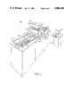
- FIG. 1is an axonometric view of a machine utilizing the illumination system of this invention
- FIG. 2is a cross sectional partly schematic view taken along line 2--2 of FIG. 1 of a preferred illumination system according to this invention
- FIG. 3is an axonometric view of the elliptical reflector
- FIG. 4is a representative intensity signal provided by a detector to indicate the presence of track and substrate material
- FIG. 5is a schematic diagram of a circuit for displaying the intensity of the sensed reflected radiation and comparing that intensity with a reference signal to indicate errors in the printed wiring board;
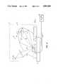
- FIG. 6is a simplified partly schematic cross-sectional view of an alternative embodiment which employs a beam splitter for reducing the effect of retroreflection.
- An elliptical reflector illumination system for inspecting printed wiring boardsmay be accomplished with an elliptical reflector element for mounting above the board with a region of the board at a first elliptical focus.
- a light sourceis mounted at a second focus of the elliptical reflector for uniformly illuminating substantially all facets of the region of the board at the first focus.
- Detector meansare provided for sensing light reflected from the illuminated facets of the board at the first focus.
- Preferred light sourcesinclude 15 to 20 watt fluorescent bulbs.
- Incandescent bulbs of a special designe.g., similar to bulbs used for aquarium or display case lighting but with an 18" long filament, may also be used.
- the reflector elementis preferably mounted between the detector and the board to be inspected and has aperture means for transmitting light reflected from the board to the detector means.
- the concave elliptical elementtypically clears the board by approximately 10 to 15 mils.
- the aperture meansmay form a longitudinal slit approximately 1/8 inch wide in the reflector.
- a preferred reflector elementconsists of aluminum, glass or quartz or other mirror materials and has a polished reflector surface.
- the detector meansmay include arrays of charge-coupled devices (CCDs).
- a typical detector meansincludes twelve to twenty one-inch detectors, each mounted in a 11/2 inch frame and including 2,048 CCDs. Each detector senses a section of a very thin (e.g., one-half mil) portion within an illuminated board region approximately 5 to 10 mils wide.
- a typical strip of copper track or foil material on the boardis between 6 and 20 mils wide.
- the reflected radiationis directed first through the slit in the elliptical reflector to the CCDs by lens and mirror systems.
- the slit in the reflector elementmay be disposed at an angle (e.g., 45°) relative to the plane of the board.
- a beam splittermay be employed to provide light to the board from the zone between the detector and normal surfaces of the board.
- the boardsare mounted on a movable single axis table such as is provided by Anorad Corp.
- the boardis moved beneath the light source and detector means so that successive regions of the board are illuminated and inspected.
- a signal indicative of the detected reflected intensitymay be employed to determine the material being detected. It may also be compared with a reference intensity for the board being inspected. Deviations of the sensed reflective light from the reference intensity are used to denote errors in the test board. To normalize the intensity of the reflected radiation sensed by the detector means and to eliminate the effects of uneven lighting, a calibration system is provided.
- This systemmay be employed at a number of stages in the production of printed wiring boards.
- the wavelengths of light used to inspect the boards at various stagesare chosen to maximize the contrast between respective materials on the board and are selected by employing appropriate filters with the light source.
- white lightis used to inspect the board.
- Such lightprovides a black and white contrast between the substrate and track material respectively.
- the sepia processlight is provided at between 3500 Angstroms and 5500 Angstroms. This provides the required contrast between the background material and the sepia traces.
- green, red or blue reflected lightindicates the photoresist material whereas a reddish color indicates the copper.
- white lightis utilized to provide a contrast between solder and substrate, respectively.
- FIG. 1a machine 10 for inspecting printed wiring boards 12 and 14.
- the boardsare mounted as more fully described in FIG. 2 to movable platform 16 which is a part of a single axis table 18.
- Platform 16is driven in the direction of arrows 20 and 22 by drive mechanisms 24 and 26.
- the platformis permitted to move approximately 22 inches and during that movement printed wiring boards 12 and 14 are passed beneath an optical head 28 which contains most elements of the illumination system of this invention.
- Head 28is held above table 18 by supports 30 and 32 and is covered by a plate 34.
- illumination system 36is mounted within head 28 and includes a concave reflector element 40, FIG. 3, mounted by brackets or any other suitable means of attachment, not shown, between end walls 41, only one of which is shown, of head 28 and having an elliptical cross section and a polished reflective inner surface 42.
- Reflector element 40also includes a narrow longitudinal aperture 43 located at an angle of approximately 45° relative to the bottom of head 28.
- An elongate fluorescent light source 44is likewise mounted to end walls 41 of head 28.
- Light source 44is arranged generally at a focus F1 of reflector 40 and extends generally parallel to the reflector.
- a plurality of detectors 46 and associated lenses 47, only one pair of which is shown,are aligned side-by-side and mounted within head 28 above reflector 40.
- Platform 16includes a plurality of holes such as 48 and 50.
- a vacuum pump 52 attached to these holes via conduit 54is activated to draw board 12 downwardly and secure it to platform 16.
- the top surface of board 12includes both substrate 56 and track material 58.
- Head 28is positioned so that a region 60 of board 12 is generally at the other focus F2 of reflector 40.
- platform 16transports printed wiring board 12 beneath head 28 in the direction of arrow 22.
- Light rays 62 of desired wavelengths from source 44are reflected from respective points of surface 42 and focused at F2 along a line that is parallel to source 44 and reflector 40.
- region 60is diffusely illuminated by light reflected, and appearing to emanate uniformly from, all points on the reflective elliptical surface 42.
- Reflected light 66 from a portion 68 of the illuminated region 60 of board 12is transmitted through aperture 43 to lenses 47 which direct the light to detectors 46 where the intensity of reflected radiation 66 is sensed.
- successive regions 60a, 60b, etc.are illuminated and light reflected from successive portions is detected.
- each detector 46includes an array of, for example, 2,048 charge-coupled devices (CCDs). As shown in FIG. 4, the output of a typical detector 46 comprises the output of all of that detector's 2,048 CCDs. That output is a function of intensity of the light reflected from the board and sensed by each of the CCDs. When that intensity rises above a threshold level T, a high degree of reflection is detected which indicates the presence of track material. However, when the intensity and therefore the output of the detector drops below threshold T, the reflection level is low and substrate material is indicated.
- CCDscharge-coupled devices
- clock pulsesare provided by pulse generator 159 to each detector 46 and to memory 160 of calibration unit 162.
- the systemPrior to inspecting a particular board or boards, the system may be calibrated to compensate for slightly varying levels of illumination in the following manner.
- the intensity sensed by each CCD from a reference board having, for example, only substrate material on its upper surfaceis multiplied by an appropriate coefficient so that all of the sensed intensities are equal.
- These 2048 calibrated coefficientsare entered into memory 162.
- detector 46provides an output, FIG. 4, and the output for each CCD is multiplied by its associated coefficient in multiplying D/A converter 164.
- the calibrated signalis then provided to a comparator 166 where it is compared with a reference signal stored in memory 168 and converted to an analog signal by D/A converter 170. Any deviation in the calibrated signal from the reference signal is denoted by error indicator 172.
- a typical indicatorincludes CRT display 172a, FIG. 1, which indicates the presence, type and location of defects in the scanned board.
- system 36significantly reduces blind spots. These are experienced when a detector directly confronts a flat or perpendicular surface of the board (e.g., when the detector is disposed along a perpendicular line from the surface of the board). The amount of board surface which the detector confronts in this manner and the extent of blind spots experienced when the detector is located at the acute angle of FIG. 2 is relatively slight.
- blind spotsmay be reduced, as shown in FIG. 6, by placing detectors 246 along the normal to board 212 and employing a beam splitter 230 which is mounted between each detector 246 and board 212.
- Light 262 from source 244is largely reflected by reflector 240 to diffusely illuminate board region 260 at focus F2.
- a portion 262a of the lightis likewise reflected from beam splitter 230 and directed to illuminate region 260.
- Reflected diffuse light 266 from portion 268 of illuminated region 260 of board 212is transmitted through beam splitter 230 and opening aperture 243 in reflector 240. The light is then directed by lens 247 to detector 246.
- Enhanced uniform illumination of the boardis provided and blind spots are greatly reduced.
- the blind spotsmay be reduced by mounting the detector slightly off of the optical axis through lens 247.
Landscapes
- Physics & Mathematics (AREA)
- Health & Medical Sciences (AREA)
- Life Sciences & Earth Sciences (AREA)
- Chemical & Material Sciences (AREA)
- Analytical Chemistry (AREA)
- Biochemistry (AREA)
- General Health & Medical Sciences (AREA)
- General Physics & Mathematics (AREA)
- Immunology (AREA)
- Pathology (AREA)
- Investigating Materials By The Use Of Optical Means Adapted For Particular Applications (AREA)
Abstract
Description
Claims (18)
Priority Applications (1)
| Application Number | Priority Date | Filing Date | Title |
|---|---|---|---|
| US07/073,013US4801810A (en) | 1987-07-13 | 1987-07-13 | Elliptical reflector illumination system for inspection of printed wiring boards |
Applications Claiming Priority (1)
| Application Number | Priority Date | Filing Date | Title |
|---|---|---|---|
| US07/073,013US4801810A (en) | 1987-07-13 | 1987-07-13 | Elliptical reflector illumination system for inspection of printed wiring boards |
Publications (1)
| Publication Number | Publication Date |
|---|---|
| US4801810Atrue US4801810A (en) | 1989-01-31 |
Family
ID=22111167
Family Applications (1)
| Application Number | Title | Priority Date | Filing Date |
|---|---|---|---|
| US07/073,013Expired - Fee RelatedUS4801810A (en) | 1987-07-13 | 1987-07-13 | Elliptical reflector illumination system for inspection of printed wiring boards |
Country Status (1)
| Country | Link |
|---|---|
| US (1) | US4801810A (en) |
Cited By (18)
| Publication number | Priority date | Publication date | Assignee | Title |
|---|---|---|---|---|
| US4914308A (en)* | 1988-12-27 | 1990-04-03 | Eastman Kodak Company | Web defect scanning apparatus with incandescent illumination means |
| US5058982A (en)* | 1989-06-21 | 1991-10-22 | Orbot Systems Ltd. | Illumination system and inspection apparatus including same |
| DE4123916A1 (en)* | 1990-07-19 | 1992-01-23 | Reinhard Malz | Identifying and classifying surface qualities and defects of object - using video camera to store reflected images arising from sequential exposure to light from distributed sources |
| US5274243A (en)* | 1992-05-29 | 1993-12-28 | Eastman Kodak Company | Cylindrical allumination system for inspection of sheet material |
| US5291392A (en)* | 1992-02-19 | 1994-03-01 | Gerber Systems Corporation | Method and apparatus for enhancing the accuracy of scanner systems |
| US5621218A (en)* | 1994-06-03 | 1997-04-15 | Nec Corporation | Method and apparatus inspecting bonding-wire status using a plurality of light sources |
| US5910651A (en)* | 1997-07-15 | 1999-06-08 | Gerber Systems Corporation | Method and apparatus for image nonlinearity compensation in scanning systems |
| WO1999066314A1 (en)* | 1998-06-16 | 1999-12-23 | Orbotech Ltd. | Illuminator for inspecting substantially flat surfaces |
| WO2002001209A1 (en)* | 2000-06-23 | 2002-01-03 | Teradyne, Inc. | Compensation system and related techniques for use in a printed circuit board inspection system |
| US6437312B1 (en) | 1999-08-05 | 2002-08-20 | Orbotech, Ltd. | Illumination for inspecting surfaces of articles |
| US20020114162A1 (en)* | 2000-08-10 | 2002-08-22 | Smith George Edward | Illumination optics and method |
| US20030202175A1 (en)* | 2002-04-24 | 2003-10-30 | Van Den Engh Gerrit J. | Compositions and methods for drop boundary detection and radiation beam alignment |
| US6788805B1 (en)* | 1999-08-03 | 2004-09-07 | Hitachi High-Tech Instruments Co., Ltd. | Electronic component-recognizing device |
| US6982785B2 (en)* | 2001-05-01 | 2006-01-03 | Van Den Engh Gerrrit J | Apparatus for determining radiation beam alignment |
| US7345758B2 (en) | 2001-05-17 | 2008-03-18 | Cytopeia | Apparatus for analyzing and sorting biological particles |
| US20110199764A1 (en)* | 2005-08-26 | 2011-08-18 | Camtek Ltd. | Device and method for controlling an angular coverage of a light beam |
| DE102016109803B3 (en)* | 2016-05-27 | 2017-07-06 | Eyec Gmbh | Inspection device and inspection method for inspecting the surface image of a flat object representing a test object |
| CN107764831A (en)* | 2016-08-23 | 2018-03-06 | 杭州海康机器人技术有限公司 | A kind of optical flat detection means |
Citations (3)
| Publication number | Priority date | Publication date | Assignee | Title |
|---|---|---|---|---|
| US4095905A (en)* | 1975-08-20 | 1978-06-20 | Hitachi, Ltd. | Surface-defect detecting device |
| US4597665A (en)* | 1983-12-09 | 1986-07-01 | Tencor Instruments | Dual collector optical flaw detector |
| US4714327A (en)* | 1986-03-14 | 1987-12-22 | Westinghouse Electric Corp. | Oblique observation attachment for microscopes |
- 1987
- 1987-07-13USUS07/073,013patent/US4801810A/ennot_activeExpired - Fee Related
Patent Citations (3)
| Publication number | Priority date | Publication date | Assignee | Title |
|---|---|---|---|---|
| US4095905A (en)* | 1975-08-20 | 1978-06-20 | Hitachi, Ltd. | Surface-defect detecting device |
| US4597665A (en)* | 1983-12-09 | 1986-07-01 | Tencor Instruments | Dual collector optical flaw detector |
| US4714327A (en)* | 1986-03-14 | 1987-12-22 | Westinghouse Electric Corp. | Oblique observation attachment for microscopes |
Cited By (33)
| Publication number | Priority date | Publication date | Assignee | Title |
|---|---|---|---|---|
| US4914308A (en)* | 1988-12-27 | 1990-04-03 | Eastman Kodak Company | Web defect scanning apparatus with incandescent illumination means |
| US5058982A (en)* | 1989-06-21 | 1991-10-22 | Orbot Systems Ltd. | Illumination system and inspection apparatus including same |
| DE4123916A1 (en)* | 1990-07-19 | 1992-01-23 | Reinhard Malz | Identifying and classifying surface qualities and defects of object - using video camera to store reflected images arising from sequential exposure to light from distributed sources |
| DE4123916C2 (en)* | 1990-07-19 | 1998-04-09 | Reinhard Malz | Method and device for dynamic detection and classification of surface features and defects of an object |
| US5291392A (en)* | 1992-02-19 | 1994-03-01 | Gerber Systems Corporation | Method and apparatus for enhancing the accuracy of scanner systems |
| US5274243A (en)* | 1992-05-29 | 1993-12-28 | Eastman Kodak Company | Cylindrical allumination system for inspection of sheet material |
| US5621218A (en)* | 1994-06-03 | 1997-04-15 | Nec Corporation | Method and apparatus inspecting bonding-wire status using a plurality of light sources |
| US5910651A (en)* | 1997-07-15 | 1999-06-08 | Gerber Systems Corporation | Method and apparatus for image nonlinearity compensation in scanning systems |
| WO1999066314A1 (en)* | 1998-06-16 | 1999-12-23 | Orbotech Ltd. | Illuminator for inspecting substantially flat surfaces |
| GB2357577A (en)* | 1998-06-16 | 2001-06-27 | Orbotech Ltd | Illuminator for inspecting substantially flat surfaces |
| US7215417B2 (en) | 1998-06-16 | 2007-05-08 | Orbotech Ltd. | Illuminator for inspecting substantially flat surfaces |
| US20060152728A1 (en)* | 1998-06-16 | 2006-07-13 | Orbotech Ltd. | Illuminator for inspecting substantially flat surfaces |
| US6847442B1 (en) | 1998-06-16 | 2005-01-25 | Orbotech, Ltd. | Illuminator for inspecting substantially flat surfaces |
| US6788805B1 (en)* | 1999-08-03 | 2004-09-07 | Hitachi High-Tech Instruments Co., Ltd. | Electronic component-recognizing device |
| US6437312B1 (en) | 1999-08-05 | 2002-08-20 | Orbotech, Ltd. | Illumination for inspecting surfaces of articles |
| US6832843B2 (en) | 1999-08-05 | 2004-12-21 | Orbotech, Ltd. | Illumination for inspecting surfaces of articles |
| WO2002001209A1 (en)* | 2000-06-23 | 2002-01-03 | Teradyne, Inc. | Compensation system and related techniques for use in a printed circuit board inspection system |
| US6760471B1 (en)* | 2000-06-23 | 2004-07-06 | Teradyne, Inc. | Compensation system and related techniques for use in a printed circuit board inspection system |
| US6829098B2 (en)* | 2000-08-10 | 2004-12-07 | Agilent Technologies, Inc. | Illumination optics and method |
| US20020114162A1 (en)* | 2000-08-10 | 2002-08-22 | Smith George Edward | Illumination optics and method |
| US6982785B2 (en)* | 2001-05-01 | 2006-01-03 | Van Den Engh Gerrrit J | Apparatus for determining radiation beam alignment |
| US20080316481A1 (en)* | 2001-05-17 | 2008-12-25 | Cytopeia | Apparatus for analyzing and sorting biological particles |
| US7345758B2 (en) | 2001-05-17 | 2008-03-18 | Cytopeia | Apparatus for analyzing and sorting biological particles |
| US7643142B2 (en) | 2001-05-17 | 2010-01-05 | Cytopeia | Apparatus for analyzing and sorting biological particles |
| US7362424B2 (en) | 2002-04-24 | 2008-04-22 | The Institute For Systems Biology | Compositions and methods for drop boundary detection and radiation beam alignment |
| US20080259342A1 (en)* | 2002-04-24 | 2008-10-23 | The Institute For Systems Biology | Compositions and methods for drop boundary detection and radiation beam alignment |
| US20030202175A1 (en)* | 2002-04-24 | 2003-10-30 | Van Den Engh Gerrit J. | Compositions and methods for drop boundary detection and radiation beam alignment |
| US7679039B2 (en) | 2002-04-24 | 2010-03-16 | The Institute For Systems Biology | Compositions and methods for drop boundary detection and radiation beam alignment |
| US20110199764A1 (en)* | 2005-08-26 | 2011-08-18 | Camtek Ltd. | Device and method for controlling an angular coverage of a light beam |
| DE102016109803B3 (en)* | 2016-05-27 | 2017-07-06 | Eyec Gmbh | Inspection device and inspection method for inspecting the surface image of a flat object representing a test object |
| EP3258244A2 (en) | 2016-05-27 | 2017-12-20 | Eyec GmbH | Inspection device and inspection method for inspecting the surface image of a flat item representing a test piece |
| US10215708B2 (en) | 2016-05-27 | 2019-02-26 | Eyec Gmbh | Inspection apparatus and inspection method for inspection of the surface appearance of a flat item that represents a test specimen |
| CN107764831A (en)* | 2016-08-23 | 2018-03-06 | 杭州海康机器人技术有限公司 | A kind of optical flat detection means |
Similar Documents
| Publication | Publication Date | Title |
|---|---|---|
| US4801810A (en) | Elliptical reflector illumination system for inspection of printed wiring boards | |
| US4538909A (en) | Circuit board inspection apparatus and method | |
| USRE37740E1 (en) | Method and apparatus for optical inspection of substrates | |
| US5610710A (en) | Dual mode illumination system for optical inspection | |
| US5684530A (en) | Continuous diffuse illumination method and apparatus | |
| US6175645B1 (en) | Optical inspection method and apparatus | |
| RU2169393C2 (en) | Device and method for checking sheet material including bank notes and securities | |
| CN100438745C (en) | Optical sensor device | |
| JP3354131B2 (en) | Lighting for surface inspection of goods | |
| US6124585A (en) | Apparatus for measuring the reflectance of strips having non-uniform color | |
| US4381152A (en) | Dimension measuring apparatus | |
| US4682040A (en) | Image pickup apparatus for a printed wiring board | |
| JP2000266681A (en) | Line illumination apparatus | |
| US5739525A (en) | Device for detecting an electronic component, and component-mounting machine provided with such a detection device | |
| KR20030015207A (en) | Imaging system | |
| US5214841A (en) | Machine for placing surface mount components | |
| JPH11260572A (en) | Lighting equipment | |
| JP2678411B2 (en) | Nori inspection method and device | |
| US20020135757A1 (en) | LCC device inspection module | |
| JPH0827239B2 (en) | Lighting equipment | |
| JP2818687B2 (en) | Fuse arrangement inspection device | |
| JP2519363B2 (en) | Wiring pattern defect inspection method on printed circuit board | |
| JP2879323B2 (en) | Imaging device | |
| KR100333222B1 (en) | Method of checking for the presence of connection balls | |
| CN223425143U (en) | AOI light source for detecting defects of circuit board |
Legal Events
| Date | Code | Title | Description |
|---|---|---|---|
| AS | Assignment | Owner name:CAMBRIDGE ROBOTIC SYSTEMS INCORPORATED, 150 COOLID Free format text:ASSIGNMENT OF ASSIGNORS INTEREST.;ASSIGNOR:KOSO, DUSAN A.;REEL/FRAME:004745/0145 Effective date:19870707 Owner name:CAMBRIDGE ROBOTIC SYSTEMS INCORPORATED, MASSACHUSE Free format text:ASSIGNMENT OF ASSIGNORS INTEREST;ASSIGNOR:KOSO, DUSAN A.;REEL/FRAME:004745/0145 Effective date:19870707 | |
| AS | Assignment | Owner name:GERBER SCIENTIFIC INSTRUMENT COMPANY, INC., THE, 8 Free format text:ASSIGNMENT OF ASSIGNORS INTEREST.;ASSIGNOR:CAMBRIDGE ROBOTIC SYSTEMS;REEL/FRAME:004824/0610 Effective date:19871204 Owner name:GERBER SCIENTIFIC INSTRUMENT COMPANY, INC., THE, A Free format text:ASSIGNMENT OF ASSIGNORS INTEREST;ASSIGNOR:CAMBRIDGE ROBOTIC SYSTEMS;REEL/FRAME:004824/0610 Effective date:19871204 | |
| FEPP | Fee payment procedure | Free format text:PAT HLDR NO LONGER CLAIMS SMALL ENT STAT AS INDIV INVENTOR (ORIGINAL EVENT CODE: LSM1); ENTITY STATUS OF PATENT OWNER: LARGE ENTITY | |
| FPAY | Fee payment | Year of fee payment:4 | |
| AS | Assignment | Owner name:GERBER SYSTEMS CORPORATION Free format text:CHANGE OF NAME;ASSIGNOR:GERBER SCIENTIFIC INSTRUMENT COMPANY, THE;REEL/FRAME:006190/0025 Effective date:19920501 | |
| REMI | Maintenance fee reminder mailed | ||
| LAPS | Lapse for failure to pay maintenance fees | ||
| FP | Lapsed due to failure to pay maintenance fee | Effective date:19970205 | |
| STCH | Information on status: patent discontinuation | Free format text:PATENT EXPIRED DUE TO NONPAYMENT OF MAINTENANCE FEES UNDER 37 CFR 1.362 |