US4801164A - Check rail lock - Google Patents
Check rail lockDownload PDFInfo
- Publication number
- US4801164A US4801164AUS07/044,239US4423987AUS4801164AUS 4801164 AUS4801164 AUS 4801164AUS 4423987 AUS4423987 AUS 4423987AUS 4801164 AUS4801164 AUS 4801164A
- Authority
- US
- United States
- Prior art keywords
- cam
- housing
- spring washer
- handle
- pair
- Prior art date
- Legal status (The legal status is an assumption and is not a legal conclusion. Google has not performed a legal analysis and makes no representation as to the accuracy of the status listed.)
- Expired - Lifetime
Links
Images

Classifications
- E—FIXED CONSTRUCTIONS
- E05—LOCKS; KEYS; WINDOW OR DOOR FITTINGS; SAFES
- E05C—BOLTS OR FASTENING DEVICES FOR WINGS, SPECIALLY FOR DOORS OR WINDOWS
- E05C3/00—Fastening devices with bolts moving pivotally or rotatively
- E05C3/02—Fastening devices with bolts moving pivotally or rotatively without latching action
- E05C3/04—Fastening devices with bolts moving pivotally or rotatively without latching action with operating handle or equivalent member rigid with the bolt
- E05C3/041—Fastening devices with bolts moving pivotally or rotatively without latching action with operating handle or equivalent member rigid with the bolt rotating about an axis perpendicular to the surface on which the fastener is mounted
- E05C3/046—Fastening devices with bolts moving pivotally or rotatively without latching action with operating handle or equivalent member rigid with the bolt rotating about an axis perpendicular to the surface on which the fastener is mounted in the form of a crescent-shaped cam
- Y—GENERAL TAGGING OF NEW TECHNOLOGICAL DEVELOPMENTS; GENERAL TAGGING OF CROSS-SECTIONAL TECHNOLOGIES SPANNING OVER SEVERAL SECTIONS OF THE IPC; TECHNICAL SUBJECTS COVERED BY FORMER USPC CROSS-REFERENCE ART COLLECTIONS [XRACs] AND DIGESTS
- Y10—TECHNICAL SUBJECTS COVERED BY FORMER USPC
- Y10S—TECHNICAL SUBJECTS COVERED BY FORMER USPC CROSS-REFERENCE ART COLLECTIONS [XRACs] AND DIGESTS
- Y10S292/00—Closure fasteners
- Y10S292/47—Sash fasteners
- Y—GENERAL TAGGING OF NEW TECHNOLOGICAL DEVELOPMENTS; GENERAL TAGGING OF CROSS-SECTIONAL TECHNOLOGIES SPANNING OVER SEVERAL SECTIONS OF THE IPC; TECHNICAL SUBJECTS COVERED BY FORMER USPC CROSS-REFERENCE ART COLLECTIONS [XRACs] AND DIGESTS
- Y10—TECHNICAL SUBJECTS COVERED BY FORMER USPC
- Y10S—TECHNICAL SUBJECTS COVERED BY FORMER USPC CROSS-REFERENCE ART COLLECTIONS [XRACs] AND DIGESTS
- Y10S292/00—Closure fasteners
- Y10S292/61—Spring devices
- Y—GENERAL TAGGING OF NEW TECHNOLOGICAL DEVELOPMENTS; GENERAL TAGGING OF CROSS-SECTIONAL TECHNOLOGIES SPANNING OVER SEVERAL SECTIONS OF THE IPC; TECHNICAL SUBJECTS COVERED BY FORMER USPC CROSS-REFERENCE ART COLLECTIONS [XRACs] AND DIGESTS
- Y10—TECHNICAL SUBJECTS COVERED BY FORMER USPC
- Y10T—TECHNICAL SUBJECTS COVERED BY FORMER US CLASSIFICATION
- Y10T292/00—Closure fasteners
- Y10T292/08—Bolts
- Y10T292/1039—Swinging and camming
- Y10T292/1041—Rigid operating means
- Y—GENERAL TAGGING OF NEW TECHNOLOGICAL DEVELOPMENTS; GENERAL TAGGING OF CROSS-SECTIONAL TECHNOLOGIES SPANNING OVER SEVERAL SECTIONS OF THE IPC; TECHNICAL SUBJECTS COVERED BY FORMER USPC CROSS-REFERENCE ART COLLECTIONS [XRACs] AND DIGESTS
- Y10—TECHNICAL SUBJECTS COVERED BY FORMER USPC
- Y10T—TECHNICAL SUBJECTS COVERED BY FORMER US CLASSIFICATION
- Y10T292/00—Closure fasteners
- Y10T292/08—Bolts
- Y10T292/1043—Swinging
- Y10T292/1075—Operating means
- Y10T292/1083—Rigid
- Y10T292/1085—Friction catch
- Y—GENERAL TAGGING OF NEW TECHNOLOGICAL DEVELOPMENTS; GENERAL TAGGING OF CROSS-SECTIONAL TECHNOLOGIES SPANNING OVER SEVERAL SECTIONS OF THE IPC; TECHNICAL SUBJECTS COVERED BY FORMER USPC CROSS-REFERENCE ART COLLECTIONS [XRACs] AND DIGESTS
- Y10—TECHNICAL SUBJECTS COVERED BY FORMER USPC
- Y10T—TECHNICAL SUBJECTS COVERED BY FORMER US CLASSIFICATION
- Y10T292/00—Closure fasteners
- Y10T292/08—Bolts
- Y10T292/1043—Swinging
- Y10T292/1075—Operating means
- Y10T292/1083—Rigid
- Y10T292/1091—Spring-arm catch
- Y—GENERAL TAGGING OF NEW TECHNOLOGICAL DEVELOPMENTS; GENERAL TAGGING OF CROSS-SECTIONAL TECHNOLOGIES SPANNING OVER SEVERAL SECTIONS OF THE IPC; TECHNICAL SUBJECTS COVERED BY FORMER USPC CROSS-REFERENCE ART COLLECTIONS [XRACs] AND DIGESTS
- Y10—TECHNICAL SUBJECTS COVERED BY FORMER USPC
- Y10T—TECHNICAL SUBJECTS COVERED BY FORMER US CLASSIFICATION
- Y10T74/00—Machine element or mechanism
- Y10T74/20—Control lever and linkage systems
- Y10T74/20576—Elements
- Y10T74/20732—Handles
- Y10T74/20762—Shaft connections
Definitions
- This inventionpertains to a check rail lock for use with a double-hung window for drawing together the meeting rails of an upper and lower sash of the double-hung window, and locking the sash against opening movement.
- the check rail lockhas a housing which mounts a rotatable cam for movement between locked and unlocked positions and which engages a keeper in a locked position.
- a spring washeris rotatable with the cam and coacting detent structure on the spring washer and the housing releasably retains the cam in either locked or unlocked position.
- a check rail lock of the general type disclosed hereinis well known in the art.
- a housing mountable on one window sashhas a rotatable cam therein for movement between locked and unlocked positions relative to a keeper mounted on the other sash and with a handle disposed exteriorly of the housing for rotating the cam.
- a check rail lock of this typeit is also known to have structure for limiting the rotation of the cam and handle for movement between locked and unlocked positions of the cam and to have spring means for releasably retaining the cam in either locked or unlocked position.
- a check rail lock having an appearance generally similar to that disclosed hereinis shown in the Anderson U.S. Pat. No. Des. 268,643.
- a window lock having a cam with a square opening fitted to a shaft with a square sectionis shown in Chernosky, U.S. Pat. No. 4,436,328.
- a primary feature of the inventionis to provide a new and improved check rail lock having components mountable on the meeting rails the upper and lower of sash of a double-hung window and which provides for positive alignment of the meeting rails and locking thereof by rotation of a cam which coacts with a keeper and with the cam being located and releasably held in either locked or unlocked position by a relatively simple, easily assembled structure.
- An additional feature of the inventionis to provide a unique spring washer which exerts tolerance take-up and predetermined loading on a handle of the check rail lock and provides positive detent locking of the cam.
- the check rail lockhas a cam fixed to a shaft integral with a handle and which is rotatably mounted within a tubular section of the housing of the check rail lock for movement between locked and unlocked positions and a spring washer is positioned between the cam and an exposed end of the housing tubular section and keyed to the shaft for rotation therewith.
- the spring washer and exposed end of the housing tubular sectionhave coacting detent means as well as there being coacting stop surfaces on the cam and the housing whereby the cam is limited to movement between locked and unlocked positions and the detent means releasably hold the cam in either of said positions.
- An object of the inventionis to provide a check rail lock having a cam rotatably mounted within a housing by connection to a rotatable shaft integral with a handle and which is rotatably mounted in the housing and with a spring washer also rotatable with the shaft and the spring washer and housing have coacting detent means which releasably hold the cam and handle in either locked or unlocked positions.
- the spring washeralso functions to take up tolerances that may exist between the rotatable shaft and its cam.
- Still another object of the inventionis to provide a check rail lock: comprising, a housing, a cam, means rotatably mounting the cam on the housing for rotation between locked and unlocked positions, coacting stop means on the housing and cam for limiting the rotation of the cam to movement between said locked and unlocked positions, a spring washer rotatable with said cam, and coacting detent means on said housing and spring washer for releasably holding the cam in either locked or unlocked position.
- a further object of the inventionis to provide a check rail lock comprising, a housing with a top wall and an interior space, a tubular section of the housing depending from the top wall into said interior space and having a lower exposed end, a handle having an integral shaft rotatably mounted in said tubular section and with said shaft having a rectangular section beneath the tubular section with a pair of grooves extending axially thereof, a cam fixed to said rectangular section of the shaft and rotatable through movement of the handle between locked and unlocked positions, a spring washer between said tubular section exposed end and the cam and having a pair of tabs positioned one in each of said axially extending grooves to cause rotation of the spring washer with the shaft, a pair of diametrically opposite detent notches in said tubular section exposed end, a pair of diametrically opposite detents on said spring washer engageable in said detent notches when the cam is in either locked or unlocked position, a pair of stop shoulders on the exterior of the tubular section, and a stop member on the
- Another object of the inventionis to provide a check rail lock as defined in the preceding paragraph wherein said spring washer is generally annular with an annular body shaped both in width and in curvature to provide predetermined loading and wherein the diametrically opposite detents are formed embosses in generally planar parts of said annular body to have the formed embosses be generally parallel with the detent notches in the cam for complete seating of the detents in the detent notches.
- FIG. 1is a perspective view looking at the underside of the check rail lock housing and keeper which are shown in spaced apart relation;
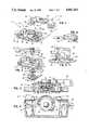
- FIG. 2is a perspective exploded view of the check rail lock housing and associated structure
- FIG. 3is an elevational view of the check rail housing and associated structure looking in the direction thereof as seen in FIG. 1 and with the cam in locked position and broken away;
- FIG. 4is a bottom plan view of the structure seen in FIG. 3;
- FIG. 5is a fragmentary sectional view taken generally along the line 5--5 in FIG. 3 and on an enlarged scale;
- FIG. 6is a bottom plan view of the handle
- FIG. 7is a perspective view similar to FIG. 1 of a second embodiment of the invention.
- FIG. 8is a plan view of the detent spring of the second embodiment
- FIG. 9is a sectional view taken generally along the line 9--9 in FIG. 8;
- FIG. 10is a sectional view taken generally along the line 10--10 in FIG. 8.
- the check rail lock in the embodiment of FIGS. 1-6has two primary components as seen in FIG. 1 with one of the components being a housing indicated generally at 10 which mounts the movable structure and the other component being a keeper indicated generally at 12.
- the housing 10which is seen looking toward the underside thereof in FIG. 1, is mounted on the meeting rail of the lower sash of a double-hung window and the keeper 12 is mounted in alignment therewith on the meeting rail of the upper sash.
- Each of these componentscan be mounted on their respective meeting rails by fastening means such as screws which can extend through openings 14 and 15 of the housing 10 and openings 16 and 17 of the keeper 12.
- the housing 10has a top wall 20 and an outer face with a pair of vertically extending contoured lugs 21 and 22 which can coact with a pair of similarly shaped recesses 23 and 24 on an inner face of the keeper 12. These lugs and recesses function to bring the housing and keeper into alignment as the meeting rails come together upon closing of the window.
- the structure associated with the housing 10is shown in the exploded perspective view of FIG. 2 and includes a handle 30 having an integral shaft 31 with a rectangular section 32 at the lower end thereof having a pair of axially extending grooves 33 and 34. Additional movable structure includes a spring washer 35 and a cam 36. Additionally, handle 30 has an orientation lug 69 which positively engages cam 36 at orientation pocket 70 to assure correct assembly location.
- the shaft 31is rotatably mounted within a tubular section 40 of the housing which depends from the top wall 20 with the rectangular section 32 of the shaft extending below the tubular section 40.
- the spring washer 35 and the cam 36are mounted on the rectangular section 32 and these parts are held in assembled relation, as seen in FIG. 3, by means of a spun deformation of an end of the shaft to provide an enlarged rounded end 42.
- the spring washer 35is formed as an annular member to surround the rectangular section 32 of the shaft and has a pair of tabs 44 and 45 formed upwardly from the plane of the spring washer for rotational interlocking relation in the axially extending grooves 33 and 34 whereby the spring washer is caused to rotate with the shaft.
- the cam 36has a raised spiral cam flange 50 which in the unlocked position of the check rail lock is disposed within the interior space of the housing and which can be moved to an engaging position behind a locking member 52 on the keeper having a curved surface 53.
- a strengthening rib 54having generally the same curvature as the cam flange 50 extends downwardly from the cam 36.
- the camhas a square opening 55 for mounting on the rectangular section 32 of the shaft.
- the tubular section 40 of the housinghas a pair of stop shoulders 60 and 61 for coaction with a stop member 62 on the upper surface of the cam whereby the stop member coacts with the stop shoulders to limit rotation of the cam between locked and unlocked positions.
- the coaction between the stop member and the stop shoulder 61is shown in FIG. 4 when the cam is in locked position.
- the spring washer 35 and the tubular section 40 of the housinghave coacting detent means for releasably holding the cam in either locked or unlocked position.
- This detent meansincludes a pair of diametrically opposite detent notches 65 and 66 formed in an exposed lower face of the tubular section 40 and a pair of diametrically opposite detents 67 and 68 deformed upwardly in the annular body of the spring washer and which engage in the detent notches 65 and 66 when the cam 36 is in either locked or unlocked position.
- the camcan be releasably held in either locked or unlocked position by use of spring means in the form of a spring washer which can be assembled onto the shaft with the cam in a single assembly operation and with the spring washer providing dual functions of tolerance take-up and releasable locking of the cam.
- FIGS. 7-10A second embodiment of the check rail lock is shown in FIGS. 7-10 wherein parts which are of the same construction as in the first embodiment are given the same reference numeral with a prime affixed thereto.
- the housing 10'rotatably mounts a handle 30' with a cam 36' being rotatable within a recess of the housing between two positions. One position is an unlocked position while the other position is a locked position in association with a keeper as disclosed in the embodiment of FIGS. 1-6.
- the cam 36'is fixed to a rectangular section 32' of a shaft 31' integral with the handle.
- the shaft 31'is rotatably mounted with a downwardly depending tubular section 40' of the housing.
- the lower surface of the tubular housinghas a pair of diametrically opposite detent notches 65' and 66'.
- a spring washer indicated generally at 80is fixed to the integral shaft 31' for rotation with the handle 30'.
- the spring washer 80is fitted between the upper surface of the cam 36' and the lower surface of the tubular section 40' of the housing.
- the spring washer 80is shown particularly in FIGS. 8-10.
- the spring washeris generally annular with an annular body 82 having a transverse dimension indicated at D' which is slightly greater than the transverse dimension indicated at D 2 .
- the spring washerhas a pair of diametrically opposite tabs 86 which are integral with the annular body and which extend inwardly therefrom and also extend downwardly for engaging in axially extending grooves of the integral shaft 31' whereby the spring washer is caused to rotate with the handle 30'.
- the spring washer 80has a complex shape in order to exert a predetermined load on the handle, take up tolerance in the components and provide a good detent action for the handle with extended cycle life.
- This complex shapeincludes a pair of diametrically opposite planar sections 90 and 92 of the annular body of the spring washer interconnected by portions 94 and 96 which mounts the tabs 86 and 88 and which are downwardly curved from the planar section 90. Similarly, portions 98 and 100 are downwardly curved from the planar section 92 to form the spring washer with an upwardly concave shape.
- the spring washeris made of spring steel and the concave shape acts to provide a predetermined load on the handle 30' and take up tolerance of the components because of the positioning of the spring washer between cam 36' and the tubular section 40' of the housing.
- Portions 94, 96, 98 and 100 of the annular bodyare slightly reduced in width adjacent the location of the tabs 86 and 88 to provide a tapered beam section and redistribute stresses in the spring washer to thereby increase cycle life of the spring washer.
- the spring washerhas a pair of diametrically opposite detents 101 and 102 formed in the respective planar sections 90 and 92 by formed embosses to extend upwardly from the planar sections and to coact with the detent notches 65' and 66'.
- planar sections 90 and 92are formed from the annular body with a slight bend at 110 and 112 to have the planar sections extend substantially horizontally as seen in the Figures and to thus lie generally parallel to the underside of the tubular section 40' of the housing. This assures that the detents 101 and 102 in the planar sections will fully seat along the length of the detent notches 65' and 66'. These detents are formed in the widest part of the annular body to have maximum length to further assure good positive detent action between the detents and the detent notches.
- the detents and detent notchescoact to releasably hold the handle 30' in either of two positions.
- the one positionbeing with the cam in a locked position in association with the keeper and in the other position the cam is released from the keeper and is enclosed within the perimeter of the housing 10'.
Landscapes
- Engineering & Computer Science (AREA)
- Mechanical Engineering (AREA)
- Snaps, Bayonet Connections, Set Pins, And Snap Rings (AREA)
Abstract
Description
Claims (3)
Priority Applications (1)
| Application Number | Priority Date | Filing Date | Title |
|---|---|---|---|
| US07/044,239US4801164A (en) | 1986-01-22 | 1987-04-30 | Check rail lock |
Applications Claiming Priority (2)
| Application Number | Priority Date | Filing Date | Title |
|---|---|---|---|
| US06/821,004US4736972A (en) | 1986-01-22 | 1986-01-22 | Check rail lock |
| US07/044,239US4801164A (en) | 1986-01-22 | 1987-04-30 | Check rail lock |
Related Parent Applications (1)
| Application Number | Title | Priority Date | Filing Date |
|---|---|---|---|
| US06/821,004Continuation-In-PartUS4736972A (en) | 1986-01-22 | 1986-01-22 | Check rail lock |
Publications (1)
| Publication Number | Publication Date |
|---|---|
| US4801164Atrue US4801164A (en) | 1989-01-31 |
Family
ID=26721312
Family Applications (1)
| Application Number | Title | Priority Date | Filing Date |
|---|---|---|---|
| US07/044,239Expired - LifetimeUS4801164A (en) | 1986-01-22 | 1987-04-30 | Check rail lock |
Country Status (1)
| Country | Link |
|---|---|
| US (1) | US4801164A (en) |
Cited By (72)
| Publication number | Priority date | Publication date | Assignee | Title |
|---|---|---|---|---|
| US4930820A (en)* | 1989-10-16 | 1990-06-05 | Truth Incorporated | Cam handle lock |
| USD313162S (en) | 1988-11-23 | 1990-12-25 | Certainteed Corporation | Latch body for a pivoting window sash |
| USD313161S (en) | 1988-11-23 | 1990-12-25 | Certainteed Corporation | Latch handle for a pivoting window sash |
| US5110165A (en)* | 1991-02-12 | 1992-05-05 | Truth Division Of Spx Corporation | Biased check rail lock |
| US5161839A (en)* | 1991-07-25 | 1992-11-10 | Truth Division Of Spx Corporation | Check rail lock and method of making check rail lock paintable after assembly |
| US5219193A (en)* | 1992-05-22 | 1993-06-15 | Truth Division Of Spx Corporation | Forced entry resistant check rail lock |
| US5437173A (en)* | 1993-02-18 | 1995-08-01 | Truth Division Of Spx Corporation | Window lock with indicator |
| US5448857A (en)* | 1994-03-25 | 1995-09-12 | Truth Hardware Corporation | Locking system for a double hung window |
| US5454609A (en)* | 1993-08-19 | 1995-10-03 | Slocomb Industries, Inc. | Snap in latch assembly for windows |
| USD369290S (en) | 1995-06-23 | 1996-04-30 | Allen-Stevens Corporation | Sash lock and keeper assembly |
| US5582445A (en)* | 1993-02-04 | 1996-12-10 | Andersen Corporation | Sash lock |
| US5582442A (en)* | 1995-09-15 | 1996-12-10 | Truth Hardware Corporation | Latch assembly and manufacturing and painting processes |
| USD380957S (en)* | 1996-04-26 | 1997-07-15 | Andersen Corporation | Sash lock |
| US5741032A (en)* | 1996-06-18 | 1998-04-21 | Reflectolite Products Company, Inc. | Sash lock |
| US5769469A (en)* | 1995-06-14 | 1998-06-23 | Zemke; William L. | Window latch |
| USD418737S (en)* | 1998-12-11 | 2000-01-11 | Andersen Corporation | Sash lock |
| US6142541A (en)* | 1998-11-24 | 2000-11-07 | Truth Hardware Corporation | Pick resistant sash lock |
| US6412834B1 (en)* | 1999-10-18 | 2002-07-02 | Interlock Group Limited | Window fastener |
| US6478347B1 (en) | 2000-05-10 | 2002-11-12 | Caldwell Manufacturing Company | Wind-resistant sweep lock |
| US6523868B1 (en) | 2000-05-10 | 2003-02-25 | Caldwell Manufacturing Company | Wind-resistant window sash lock |
| US6568723B2 (en)* | 2001-09-24 | 2003-05-27 | Ashland Paroducts, Inc. | Sash lock for a sash window |
| US20030155777A1 (en)* | 2002-01-29 | 2003-08-21 | Eslick Vincent F. | Forced entry resistance device for sash lock |
| US6767038B1 (en) | 2001-02-08 | 2004-07-27 | G-U Hardware, Inc. | Multi-point casement handle |
| US20040217600A1 (en)* | 2003-02-28 | 2004-11-04 | Kevin Argo | Latch assembly for sliding door |
| US20040221513A1 (en)* | 2003-05-06 | 2004-11-11 | Dean Pettit | Forced entry resistance device for sash window assembly |
| US6877784B2 (en)* | 2002-05-03 | 2005-04-12 | Andersen Corporation | Tilt latch mechanism for hung windows |
| US20050218658A1 (en)* | 2004-04-01 | 2005-10-06 | Lawrence Barry G | Casement window lock |
| US6962024B1 (en) | 2001-07-18 | 2005-11-08 | Hughes Supply Company Of Thomasville, Inc. | Locking window having a sweep latch |
| US7017957B2 (en) | 2001-09-24 | 2006-03-28 | Ashland Products, Inc. | Sash lock for a sash window |
| US20060087130A1 (en)* | 2004-10-22 | 2006-04-27 | Luke Liang | Window sash latch |
| US7063361B1 (en)* | 2002-05-30 | 2006-06-20 | Barry Gene Lawrence | Locking window |
| USD527613S1 (en) | 2005-04-27 | 2006-09-05 | Truth Hardware Corporation | Lock housing |
| USD528400S1 (en) | 2005-05-02 | 2006-09-19 | Truth Hardware Corporation | Escutcheon and handle for window lock |
| US20070209281A1 (en)* | 2001-11-07 | 2007-09-13 | Flory Edward C | Integrated tilt/sash lock assembly |
| USD553950S1 (en) | 2006-07-26 | 2007-10-30 | Newell Operating Company | Sash lock housing |
| USD554971S1 (en) | 2006-07-26 | 2007-11-13 | Newell Operating Company | Sash lock handle |
| USD554973S1 (en) | 2006-07-26 | 2007-11-13 | Newell Operating Company | Sash lock housing |
| US20080012358A1 (en)* | 2006-06-02 | 2008-01-17 | Luke Liang | Sweep lock |
| USD575627S1 (en) | 2007-11-16 | 2008-08-26 | Newell Operating Company | Sash lock housing |
| US7510221B2 (en) | 2006-02-09 | 2009-03-31 | Newell Operating Company | Sash lock assembly having forced entry resistance |
| US20090179436A1 (en)* | 2007-11-09 | 2009-07-16 | Albert Sagalara | Positive action lock for sliding windows |
| US20090189398A1 (en)* | 2008-01-30 | 2009-07-30 | Lawrence Barry G | Security lock for a sash type window |
| USD597398S1 (en)* | 2008-08-15 | 2009-08-04 | Truth Hardware Corporation | Window lock handle and cover |
| US7665775B1 (en) | 2001-08-03 | 2010-02-23 | Hughes Supply Company Of Thomasville, Inc. | Locking window having a cam latch |
| US20100050528A1 (en)* | 2002-11-07 | 2010-03-04 | Newell Operating Company | Integrated tilt/sash lock assembly |
| US20100111598A1 (en)* | 2007-05-08 | 2010-05-06 | Franz Baur | Connecting means and method of producing a connection between a first component and a second component |
| US20110271720A1 (en)* | 2010-05-04 | 2011-11-10 | Cmech (Guangzhou) Industrial Ltd. | Novel dial-type window lock |
| US20120104772A1 (en)* | 2010-10-28 | 2012-05-03 | Lopes Antonio Jorge Freire | Door Handle Type Closure System |
| US8205919B2 (en) | 2008-04-28 | 2012-06-26 | Newell Operating Company | Sash lock with forced entry resistance |
| US8205920B2 (en) | 2008-04-28 | 2012-06-26 | Newell Operating Company | Sash lock with forced entry resistance |
| US20130291605A1 (en)* | 2012-05-02 | 2013-11-07 | Celestica Technology Consultancy (Shanghai) Co., Ltd | Lock and the application thereof |
| US20140327249A1 (en)* | 2013-05-02 | 2014-11-06 | Joseph Snyder | Internal Locking Mechanism for an Externally Locked Door |
| US9840860B2 (en) | 2009-05-29 | 2017-12-12 | Vision Industries Group, Inc. | Double-action, adjustable, after-market sash stop |
| US10006232B2 (en) | 2006-03-28 | 2018-06-26 | Vision Industries Group | Window vent stop with flexible side engagement pieces |
| US20180230710A1 (en)* | 2017-02-16 | 2018-08-16 | Vision Industries Group, Inc. | Tamper-Resistant Lock |
| US10107021B1 (en) | 2006-03-28 | 2018-10-23 | Vision Industries Group, Inc. | Window vent stop with plastic spring member for bi-directional biasing of the tumbler |
| US10119310B2 (en) | 2014-03-06 | 2018-11-06 | Vision Industries Group, Inc. | Combination sash lock and tilt latch with improved interconnection for blind mating of the latch to the lock |
| US10594880B2 (en)* | 2015-12-08 | 2020-03-17 | Ricoh Company, Ltd. | Lock lever structure, unit, and image forming apparatus |
| US10704297B2 (en) | 2014-03-06 | 2020-07-07 | Vision Industries, Inc. | Impact resistant lock and tilt latch combination for a sliding sash window |
| US10738516B1 (en)* | 2017-08-21 | 2020-08-11 | Barry G. Lawrence | Window lock with adjustable reinforcement members |
| US10844636B2 (en) | 2017-05-23 | 2020-11-24 | Vision Industries Group, Inc. | Combination forced entry resistant sash lock and tilt latch, also functioning as a window opening control device |
| US10844642B2 (en) | 2014-03-06 | 2020-11-24 | Vision Industries Group, Inc. | Combination four-position sash lock and tilt latch also functioning as a window opening control device |
| US10865592B2 (en) | 2014-03-06 | 2020-12-15 | Vision Industries Group, Inc. | Sash lock and tilt latch also functioning as a window vent stop, with automatic locking upon closure |
| US11047157B1 (en) | 2006-03-28 | 2021-06-29 | Vision Industries Group, Inc. | Vent stop |
| US11118376B1 (en) | 2017-10-18 | 2021-09-14 | Vision Industries Group, Inc. | Combination sash lock and tilt latch and slidable window vent stop |
| US11168492B1 (en)* | 2017-02-16 | 2021-11-09 | Vision Industries Group, Inc. | Tamper resistant sash lock |
| US11168495B1 (en) | 2018-08-01 | 2021-11-09 | Vision Industries Group, Inc. | Automatically resetting window vent stop with dual safety features |
| US11187010B1 (en) | 2019-09-19 | 2021-11-30 | Vision Industries, Inc. | Forced-entry-resistant sash lock |
| US11220845B2 (en) | 2015-06-08 | 2022-01-11 | Andersen Corporation | Powered sash lock and control systems therefor |
| US20220072363A1 (en)* | 2020-09-06 | 2022-03-10 | Peloton Interactive, Inc. | Seat assembly system and methods |
| US12359477B1 (en) | 2022-06-16 | 2025-07-15 | Vision Industries Group, Inc. | Window sash lock configured for screwless snap-in installation onto a meeting rail |
| US12428886B1 (en) | 2022-06-16 | 2025-09-30 | Vision Industries Group, Inc. | Forced entry resistant sash lock also configured to snap into the meeting rail of the sash window |
Citations (13)
| Publication number | Priority date | Publication date | Assignee | Title |
|---|---|---|---|---|
| US423761A (en)* | 1890-03-18 | Fastener for the meeting-rails of sashes | ||
| FR330696A (en)* | 1903-03-28 | 1903-08-24 | Pierre Albert Raymond | Spring-loaded turnstile applicable to leather goods, saddlery, basketwork |
| US952277A (en)* | 1909-12-03 | 1910-03-15 | Thomas M Pilarski | Door-latch. |
| US1139575A (en)* | 1914-02-09 | 1915-05-18 | Victor A Pitsch | Stove. |
| US1203980A (en)* | 1916-05-20 | 1916-11-07 | Matthew Clarke | Saw-holder. |
| US1575330A (en)* | 1925-05-25 | 1926-03-02 | Mt Carmel Mfg Company | Adjustable escutcheon |
| US2258617A (en)* | 1939-10-21 | 1941-10-14 | Harry A Knauff | Latching device |
| GB837452A (en)* | 1959-11-05 | 1960-06-15 | John Freeman Cuss | Fasteners for panels and the like |
| US3119591A (en)* | 1963-06-04 | 1964-01-28 | Delbar Products | Hinged joint support, as for a rear view mirror mounting |
| US3135542A (en)* | 1962-05-14 | 1964-06-02 | H B Ives Company | Window sash fastener |
| US3811718A (en)* | 1972-08-10 | 1974-05-21 | Truth Inc | Sash lock |
| US3951444A (en)* | 1973-02-01 | 1976-04-20 | Elixir Industries | Lock assembly with resilient latch |
| US4436328A (en)* | 1982-02-22 | 1984-03-13 | Chernosky John E | Keyless lock |
- 1987
- 1987-04-30USUS07/044,239patent/US4801164A/ennot_activeExpired - Lifetime
Patent Citations (13)
| Publication number | Priority date | Publication date | Assignee | Title |
|---|---|---|---|---|
| US423761A (en)* | 1890-03-18 | Fastener for the meeting-rails of sashes | ||
| FR330696A (en)* | 1903-03-28 | 1903-08-24 | Pierre Albert Raymond | Spring-loaded turnstile applicable to leather goods, saddlery, basketwork |
| US952277A (en)* | 1909-12-03 | 1910-03-15 | Thomas M Pilarski | Door-latch. |
| US1139575A (en)* | 1914-02-09 | 1915-05-18 | Victor A Pitsch | Stove. |
| US1203980A (en)* | 1916-05-20 | 1916-11-07 | Matthew Clarke | Saw-holder. |
| US1575330A (en)* | 1925-05-25 | 1926-03-02 | Mt Carmel Mfg Company | Adjustable escutcheon |
| US2258617A (en)* | 1939-10-21 | 1941-10-14 | Harry A Knauff | Latching device |
| GB837452A (en)* | 1959-11-05 | 1960-06-15 | John Freeman Cuss | Fasteners for panels and the like |
| US3135542A (en)* | 1962-05-14 | 1964-06-02 | H B Ives Company | Window sash fastener |
| US3119591A (en)* | 1963-06-04 | 1964-01-28 | Delbar Products | Hinged joint support, as for a rear view mirror mounting |
| US3811718A (en)* | 1972-08-10 | 1974-05-21 | Truth Inc | Sash lock |
| US3951444A (en)* | 1973-02-01 | 1976-04-20 | Elixir Industries | Lock assembly with resilient latch |
| US4436328A (en)* | 1982-02-22 | 1984-03-13 | Chernosky John E | Keyless lock |
Cited By (93)
| Publication number | Priority date | Publication date | Assignee | Title |
|---|---|---|---|---|
| USD313162S (en) | 1988-11-23 | 1990-12-25 | Certainteed Corporation | Latch body for a pivoting window sash |
| USD313161S (en) | 1988-11-23 | 1990-12-25 | Certainteed Corporation | Latch handle for a pivoting window sash |
| US4930820A (en)* | 1989-10-16 | 1990-06-05 | Truth Incorporated | Cam handle lock |
| AU621197B2 (en)* | 1989-10-16 | 1992-03-05 | Spx Corporation | Cam handle lock |
| US5110165A (en)* | 1991-02-12 | 1992-05-05 | Truth Division Of Spx Corporation | Biased check rail lock |
| US5161839A (en)* | 1991-07-25 | 1992-11-10 | Truth Division Of Spx Corporation | Check rail lock and method of making check rail lock paintable after assembly |
| US5219193A (en)* | 1992-05-22 | 1993-06-15 | Truth Division Of Spx Corporation | Forced entry resistant check rail lock |
| US5582445A (en)* | 1993-02-04 | 1996-12-10 | Andersen Corporation | Sash lock |
| US5437173A (en)* | 1993-02-18 | 1995-08-01 | Truth Division Of Spx Corporation | Window lock with indicator |
| US5454609A (en)* | 1993-08-19 | 1995-10-03 | Slocomb Industries, Inc. | Snap in latch assembly for windows |
| US5448857A (en)* | 1994-03-25 | 1995-09-12 | Truth Hardware Corporation | Locking system for a double hung window |
| US5769469A (en)* | 1995-06-14 | 1998-06-23 | Zemke; William L. | Window latch |
| USD369290S (en) | 1995-06-23 | 1996-04-30 | Allen-Stevens Corporation | Sash lock and keeper assembly |
| US5582442A (en)* | 1995-09-15 | 1996-12-10 | Truth Hardware Corporation | Latch assembly and manufacturing and painting processes |
| USD380957S (en)* | 1996-04-26 | 1997-07-15 | Andersen Corporation | Sash lock |
| US5741032A (en)* | 1996-06-18 | 1998-04-21 | Reflectolite Products Company, Inc. | Sash lock |
| US6142541A (en)* | 1998-11-24 | 2000-11-07 | Truth Hardware Corporation | Pick resistant sash lock |
| USD418737S (en)* | 1998-12-11 | 2000-01-11 | Andersen Corporation | Sash lock |
| US6412834B1 (en)* | 1999-10-18 | 2002-07-02 | Interlock Group Limited | Window fastener |
| US6478347B1 (en) | 2000-05-10 | 2002-11-12 | Caldwell Manufacturing Company | Wind-resistant sweep lock |
| US6523868B1 (en) | 2000-05-10 | 2003-02-25 | Caldwell Manufacturing Company | Wind-resistant window sash lock |
| US6767038B1 (en) | 2001-02-08 | 2004-07-27 | G-U Hardware, Inc. | Multi-point casement handle |
| US6962024B1 (en) | 2001-07-18 | 2005-11-08 | Hughes Supply Company Of Thomasville, Inc. | Locking window having a sweep latch |
| US7665775B1 (en) | 2001-08-03 | 2010-02-23 | Hughes Supply Company Of Thomasville, Inc. | Locking window having a cam latch |
| US6568723B2 (en)* | 2001-09-24 | 2003-05-27 | Ashland Paroducts, Inc. | Sash lock for a sash window |
| US7017957B2 (en) | 2001-09-24 | 2006-03-28 | Ashland Products, Inc. | Sash lock for a sash window |
| US8020904B2 (en)* | 2001-11-07 | 2011-09-20 | Newell Operating Company | Integrated tilt/sash lock assembly |
| US20070209281A1 (en)* | 2001-11-07 | 2007-09-13 | Flory Edward C | Integrated tilt/sash lock assembly |
| US20030155777A1 (en)* | 2002-01-29 | 2003-08-21 | Eslick Vincent F. | Forced entry resistance device for sash lock |
| US6983963B2 (en)* | 2002-01-29 | 2006-01-10 | Newell Operating Company | Forced entry resistance device for sash lock |
| US7070215B2 (en) | 2002-05-03 | 2006-07-04 | Andersen Corporation | Tilt latch mechanism for hung windows |
| US6877784B2 (en)* | 2002-05-03 | 2005-04-12 | Andersen Corporation | Tilt latch mechanism for hung windows |
| US20060225354A1 (en)* | 2002-05-03 | 2006-10-12 | Andersen Corporation | Tilt latch mechanism for hung windows |
| US7063361B1 (en)* | 2002-05-30 | 2006-06-20 | Barry Gene Lawrence | Locking window |
| US8132369B2 (en)* | 2002-11-07 | 2012-03-13 | Newell Operating Company | Integrated tilt/sash lock assembly |
| US20100050528A1 (en)* | 2002-11-07 | 2010-03-04 | Newell Operating Company | Integrated tilt/sash lock assembly |
| US20040217600A1 (en)* | 2003-02-28 | 2004-11-04 | Kevin Argo | Latch assembly for sliding door |
| US6925758B2 (en) | 2003-05-06 | 2005-08-09 | Newell Operating Company | Forced entry resistance device for sash window assembly |
| US20040221513A1 (en)* | 2003-05-06 | 2004-11-11 | Dean Pettit | Forced entry resistance device for sash window assembly |
| US20050218658A1 (en)* | 2004-04-01 | 2005-10-06 | Lawrence Barry G | Casement window lock |
| US7441811B2 (en)* | 2004-04-01 | 2008-10-28 | Lawrence Barry G | Casement window lock |
| US20060087130A1 (en)* | 2004-10-22 | 2006-04-27 | Luke Liang | Window sash latch |
| US7159908B2 (en)* | 2004-10-22 | 2007-01-09 | Vision Industries Group, Inc. | Window sash latch |
| US8511724B2 (en) | 2004-10-22 | 2013-08-20 | Vision Industries Group, Inc. | Window sash latch |
| USD527613S1 (en) | 2005-04-27 | 2006-09-05 | Truth Hardware Corporation | Lock housing |
| USD528400S1 (en) | 2005-05-02 | 2006-09-19 | Truth Hardware Corporation | Escutcheon and handle for window lock |
| US7510221B2 (en) | 2006-02-09 | 2009-03-31 | Newell Operating Company | Sash lock assembly having forced entry resistance |
| US10006232B2 (en) | 2006-03-28 | 2018-06-26 | Vision Industries Group | Window vent stop with flexible side engagement pieces |
| US10053896B2 (en) | 2006-03-28 | 2018-08-21 | Vision Industries Group, Inc. | Window vent stop with flexible side engagement pieces |
| US10107021B1 (en) | 2006-03-28 | 2018-10-23 | Vision Industries Group, Inc. | Window vent stop with plastic spring member for bi-directional biasing of the tumbler |
| US11047157B1 (en) | 2006-03-28 | 2021-06-29 | Vision Industries Group, Inc. | Vent stop |
| US20080012358A1 (en)* | 2006-06-02 | 2008-01-17 | Luke Liang | Sweep lock |
| USD554973S1 (en) | 2006-07-26 | 2007-11-13 | Newell Operating Company | Sash lock housing |
| USD554971S1 (en) | 2006-07-26 | 2007-11-13 | Newell Operating Company | Sash lock handle |
| USD553950S1 (en) | 2006-07-26 | 2007-10-30 | Newell Operating Company | Sash lock housing |
| US20100111598A1 (en)* | 2007-05-08 | 2010-05-06 | Franz Baur | Connecting means and method of producing a connection between a first component and a second component |
| US8092114B2 (en)* | 2007-05-08 | 2012-01-10 | Franz Baur | Connecting means and method of producing a connection between a first component and a second component |
| US20090179436A1 (en)* | 2007-11-09 | 2009-07-16 | Albert Sagalara | Positive action lock for sliding windows |
| USD575627S1 (en) | 2007-11-16 | 2008-08-26 | Newell Operating Company | Sash lock housing |
| US7922223B2 (en)* | 2008-01-30 | 2011-04-12 | Lawrence Barry G | Security lock for a sash type window |
| US20090189398A1 (en)* | 2008-01-30 | 2009-07-30 | Lawrence Barry G | Security lock for a sash type window |
| US8205919B2 (en) | 2008-04-28 | 2012-06-26 | Newell Operating Company | Sash lock with forced entry resistance |
| US8205920B2 (en) | 2008-04-28 | 2012-06-26 | Newell Operating Company | Sash lock with forced entry resistance |
| USD597398S1 (en)* | 2008-08-15 | 2009-08-04 | Truth Hardware Corporation | Window lock handle and cover |
| US10920469B2 (en) | 2009-05-29 | 2021-02-16 | Vision Industries Group, Inc | Double-action, adjustable, after-market sash stop |
| US9840860B2 (en) | 2009-05-29 | 2017-12-12 | Vision Industries Group, Inc. | Double-action, adjustable, after-market sash stop |
| US20110271720A1 (en)* | 2010-05-04 | 2011-11-10 | Cmech (Guangzhou) Industrial Ltd. | Novel dial-type window lock |
| US8876175B2 (en)* | 2010-10-28 | 2014-11-04 | Unikey Componentes Industriais Ltda. | Door handle type closure system |
| US20120104772A1 (en)* | 2010-10-28 | 2012-05-03 | Lopes Antonio Jorge Freire | Door Handle Type Closure System |
| US9422748B2 (en)* | 2012-05-02 | 2016-08-23 | Celestica Technology Consultancy (Shanghai) Co., Ltd. | Lock and the application thereof |
| US20130291605A1 (en)* | 2012-05-02 | 2013-11-07 | Celestica Technology Consultancy (Shanghai) Co., Ltd | Lock and the application thereof |
| US20140327249A1 (en)* | 2013-05-02 | 2014-11-06 | Joseph Snyder | Internal Locking Mechanism for an Externally Locked Door |
| US10865592B2 (en) | 2014-03-06 | 2020-12-15 | Vision Industries Group, Inc. | Sash lock and tilt latch also functioning as a window vent stop, with automatic locking upon closure |
| US10323446B2 (en) | 2014-03-06 | 2019-06-18 | Vision Industries Group, Inc. | Integrated sash lock and tilt latch combination with improved interconnection capability therebetween |
| US10704297B2 (en) | 2014-03-06 | 2020-07-07 | Vision Industries, Inc. | Impact resistant lock and tilt latch combination for a sliding sash window |
| US10119310B2 (en) | 2014-03-06 | 2018-11-06 | Vision Industries Group, Inc. | Combination sash lock and tilt latch with improved interconnection for blind mating of the latch to the lock |
| US10844642B2 (en) | 2014-03-06 | 2020-11-24 | Vision Industries Group, Inc. | Combination four-position sash lock and tilt latch also functioning as a window opening control device |
| US11220845B2 (en) | 2015-06-08 | 2022-01-11 | Andersen Corporation | Powered sash lock and control systems therefor |
| US10594880B2 (en)* | 2015-12-08 | 2020-03-17 | Ricoh Company, Ltd. | Lock lever structure, unit, and image forming apparatus |
| US11168492B1 (en)* | 2017-02-16 | 2021-11-09 | Vision Industries Group, Inc. | Tamper resistant sash lock |
| US20180230710A1 (en)* | 2017-02-16 | 2018-08-16 | Vision Industries Group, Inc. | Tamper-Resistant Lock |
| US10633897B2 (en)* | 2017-02-16 | 2020-04-28 | Vision Industries Group, Inc. | Tamper-resistant lock |
| US10844636B2 (en) | 2017-05-23 | 2020-11-24 | Vision Industries Group, Inc. | Combination forced entry resistant sash lock and tilt latch, also functioning as a window opening control device |
| US10738516B1 (en)* | 2017-08-21 | 2020-08-11 | Barry G. Lawrence | Window lock with adjustable reinforcement members |
| US11118376B1 (en) | 2017-10-18 | 2021-09-14 | Vision Industries Group, Inc. | Combination sash lock and tilt latch and slidable window vent stop |
| US11168495B1 (en) | 2018-08-01 | 2021-11-09 | Vision Industries Group, Inc. | Automatically resetting window vent stop with dual safety features |
| US11187010B1 (en) | 2019-09-19 | 2021-11-30 | Vision Industries, Inc. | Forced-entry-resistant sash lock |
| US20220072363A1 (en)* | 2020-09-06 | 2022-03-10 | Peloton Interactive, Inc. | Seat assembly system and methods |
| US11602665B2 (en)* | 2020-09-06 | 2023-03-14 | Peloton Interactive, Inc. | Seat assembly system and methods |
| US20230181967A1 (en)* | 2020-09-06 | 2023-06-15 | Peloton Interactive, Inc. | Seat assembly systems and methods |
| US12251598B2 (en)* | 2020-09-06 | 2025-03-18 | Peloton Interactive, Inc. | Seat assembly systems and methods |
| US12359477B1 (en) | 2022-06-16 | 2025-07-15 | Vision Industries Group, Inc. | Window sash lock configured for screwless snap-in installation onto a meeting rail |
| US12428886B1 (en) | 2022-06-16 | 2025-09-30 | Vision Industries Group, Inc. | Forced entry resistant sash lock also configured to snap into the meeting rail of the sash window |
Similar Documents
| Publication | Publication Date | Title |
|---|---|---|
| US4801164A (en) | Check rail lock | |
| US4736972A (en) | Check rail lock | |
| US4095829A (en) | Window lock | |
| US4186952A (en) | Turn button latch | |
| CA2256643C (en) | Pick resistant sash lock | |
| US6568723B2 (en) | Sash lock for a sash window | |
| US6349576B2 (en) | Lockable sash assembly | |
| US4475311A (en) | Custodial latch assembly for windows and the like | |
| US4076289A (en) | Lock for a slidable door | |
| US5492380A (en) | Door latch operating assembly | |
| US4646547A (en) | Dead bolt combination lock | |
| US4513771A (en) | Air valve | |
| CN109372330B (en) | Linkage lock system with limiting lock function | |
| US2978267A (en) | Latch construction | |
| US4022039A (en) | Key ejector lock | |
| US2382756A (en) | Hasp lock | |
| US2558361A (en) | Locking mechanism of spring projected latching bolt type | |
| US4648252A (en) | Sliding door lock | |
| CN113738184A (en) | Side lock, window lock and window | |
| US2225545A (en) | Lock construction | |
| US2505858A (en) | Latch | |
| CN218467343U (en) | Reset mechanism of door lock handle | |
| JPH0512569U (en) | Lock plate mounting structure for locks | |
| JPS5838847Y2 (en) | Crescent lock with locking device | |
| EP0312381A2 (en) | Fastenings for closure members |
Legal Events
| Date | Code | Title | Description |
|---|---|---|---|
| AS | Assignment | Owner name:TRUTH INCORPORATED, A MINNESOTA CORP. Free format text:ASSIGNMENT OF ASSIGNORS INTEREST.;ASSIGNOR:MOSCH, DUANE L.;REEL/FRAME:004729/0495 Effective date:19870420 | |
| STCF | Information on status: patent grant | Free format text:PATENTED CASE | |
| FEPP | Fee payment procedure | Free format text:PAYOR NUMBER ASSIGNED (ORIGINAL EVENT CODE: ASPN); ENTITY STATUS OF PATENT OWNER: LARGE ENTITY | |
| AS | Assignment | Owner name:SPX CORPORATION A CORPORATION OF DE Free format text:MERGER;ASSIGNORS:A.W. ANDERBERG MANUFACTURING COMPANY;OTC HOLDINGS, INC.;TRUTH INCORPORATED;AND OTHERS;REEL/FRAME:005722/0385 Effective date:19901130 | |
| FPAY | Fee payment | Year of fee payment:4 | |
| AS | Assignment | Owner name:TRUTH HARDWARE CORPORATION, MINNESOTA Free format text:ASSIGNMENT OF ASSIGNORS INTEREST;ASSIGNOR:TRUTH DIVISION SPX CORPORATION;REEL/FRAME:006763/0240 Effective date:19931105 | |
| FEPP | Fee payment procedure | Free format text:PAYER NUMBER DE-ASSIGNED (ORIGINAL EVENT CODE: RMPN); ENTITY STATUS OF PATENT OWNER: LARGE ENTITY Free format text:PAYOR NUMBER ASSIGNED (ORIGINAL EVENT CODE: ASPN); ENTITY STATUS OF PATENT OWNER: LARGE ENTITY | |
| FPAY | Fee payment | Year of fee payment:8 | |
| FPAY | Fee payment | Year of fee payment:12 |