US4801138A - Wearable apparatus for exercising body joints - Google Patents
Wearable apparatus for exercising body jointsDownload PDFInfo
- Publication number
- US4801138A US4801138AUS07/127,113US12711387AUS4801138AUS 4801138 AUS4801138 AUS 4801138AUS 12711387 AUS12711387 AUS 12711387AUS 4801138 AUS4801138 AUS 4801138A
- Authority
- US
- United States
- Prior art keywords
- cylinder
- appliance according
- portable appliance
- fluid
- piston
- Prior art date
- Legal status (The legal status is an assumption and is not a legal conclusion. Google has not performed a legal analysis and makes no representation as to the accuracy of the status listed.)
- Expired - Lifetime
Links
- 239000012530fluidSubstances0.000claimsabstractdescription79
- 230000033001locomotionEffects0.000claimsabstractdescription33
- 230000005540biological transmissionEffects0.000claimsabstractdescription13
- 230000000712assemblyEffects0.000claimsdescription13
- 238000000429assemblyMethods0.000claimsdescription13
- 230000004044responseEffects0.000claimsdescription2
- 230000003134recirculating effectEffects0.000claims1
- 230000003189isokinetic effectEffects0.000abstractdescription2
- 210000002414legAnatomy0.000description22
- 238000010276constructionMethods0.000description14
- 210000003127kneeAnatomy0.000description13
- 210000000629knee jointAnatomy0.000description13
- 210000003414extremityAnatomy0.000description7
- 210000003205muscleAnatomy0.000description7
- 210000000689upper legAnatomy0.000description7
- 210000004712air sacAnatomy0.000description5
- 230000003750conditioning effectEffects0.000description5
- 244000309466calfSpecies0.000description4
- 230000000694effectsEffects0.000description4
- 238000000034methodMethods0.000description4
- 239000004033plasticSubstances0.000description4
- 229920003023plasticPolymers0.000description4
- 238000011282treatmentMethods0.000description4
- 210000003423ankleAnatomy0.000description3
- 210000001513elbowAnatomy0.000description3
- 239000000463materialSubstances0.000description3
- 230000007246mechanismEffects0.000description3
- 239000012858resilient materialSubstances0.000description3
- 230000008261resistance mechanismEffects0.000description3
- 125000006850spacer groupChemical group0.000description3
- 206010073713Musculoskeletal injuryDiseases0.000description2
- 208000027418Wounds and injuryDiseases0.000description2
- 230000006835compressionEffects0.000description2
- 238000007906compressionMethods0.000description2
- 230000006378damageEffects0.000description2
- 230000003247decreasing effectEffects0.000description2
- 229920001821foam rubberPolymers0.000description2
- 208000014674injuryDiseases0.000description2
- 230000001225therapeutic effectEffects0.000description2
- 238000002560therapeutic procedureMethods0.000description2
- 238000009423ventilationMethods0.000description2
- 210000000707wristAnatomy0.000description2
- 208000034656ContusionsDiseases0.000description1
- 208000016593Knee injuryDiseases0.000description1
- 239000004677NylonSubstances0.000description1
- 239000004743PolypropyleneSubstances0.000description1
- 229920006362Teflon®Polymers0.000description1
- 229910052782aluminiumInorganic materials0.000description1
- XAGFODPZIPBFFR-UHFFFAOYSA-NaluminiumChemical compound[Al]XAGFODPZIPBFFR-UHFFFAOYSA-N0.000description1
- 210000000544articulatio talocruralisAnatomy0.000description1
- 230000008901benefitEffects0.000description1
- 201000010099diseaseDiseases0.000description1
- 208000037265diseases, disorders, signs and symptomsDiseases0.000description1
- 239000003814drugSubstances0.000description1
- 230000009977dual effectEffects0.000description1
- 229920001971elastomerPolymers0.000description1
- 239000006260foamSubstances0.000description1
- 210000002683footAnatomy0.000description1
- 239000002783friction materialSubstances0.000description1
- 210000003041ligamentAnatomy0.000description1
- 230000013011matingEffects0.000description1
- 229910052751metalInorganic materials0.000description1
- 239000002184metalSubstances0.000description1
- 150000002739metalsChemical class0.000description1
- 229920001778nylonPolymers0.000description1
- 230000000399orthopedic effectEffects0.000description1
- -1polypropylenePolymers0.000description1
- 229920001155polypropylenePolymers0.000description1
- 230000002028prematureEffects0.000description1
- 230000008569processEffects0.000description1
- 230000009467reductionEffects0.000description1
- 210000002832shoulderAnatomy0.000description1
- 210000001519tissueAnatomy0.000description1
- 238000011144upstream manufacturingMethods0.000description1
- 210000003857wrist jointAnatomy0.000description1
Images


Classifications
- A—HUMAN NECESSITIES
- A63—SPORTS; GAMES; AMUSEMENTS
- A63B—APPARATUS FOR PHYSICAL TRAINING, GYMNASTICS, SWIMMING, CLIMBING, OR FENCING; BALL GAMES; TRAINING EQUIPMENT
- A63B21/00—Exercising apparatus for developing or strengthening the muscles or joints of the body by working against a counterforce, with or without measuring devices
- A63B21/00058—Mechanical means for varying the resistance
- A63B21/00069—Setting or adjusting the resistance level; Compensating for a preload prior to use, e.g. changing length of resistance or adjusting a valve
- A—HUMAN NECESSITIES
- A63—SPORTS; GAMES; AMUSEMENTS
- A63B—APPARATUS FOR PHYSICAL TRAINING, GYMNASTICS, SWIMMING, CLIMBING, OR FENCING; BALL GAMES; TRAINING EQUIPMENT
- A63B21/00—Exercising apparatus for developing or strengthening the muscles or joints of the body by working against a counterforce, with or without measuring devices
- A63B21/008—Exercising apparatus for developing or strengthening the muscles or joints of the body by working against a counterforce, with or without measuring devices using hydraulic or pneumatic force-resisters
- A63B21/0083—Exercising apparatus for developing or strengthening the muscles or joints of the body by working against a counterforce, with or without measuring devices using hydraulic or pneumatic force-resisters of the piston-cylinder type
- A—HUMAN NECESSITIES
- A63—SPORTS; GAMES; AMUSEMENTS
- A63B—APPARATUS FOR PHYSICAL TRAINING, GYMNASTICS, SWIMMING, CLIMBING, OR FENCING; BALL GAMES; TRAINING EQUIPMENT
- A63B21/00—Exercising apparatus for developing or strengthening the muscles or joints of the body by working against a counterforce, with or without measuring devices
- A63B21/40—Interfaces with the user related to strength training; Details thereof
- A63B21/4023—Interfaces with the user related to strength training; Details thereof the user operating the resistance directly, without additional interface
- A63B21/4025—Resistance devices worn on the user's body
- A—HUMAN NECESSITIES
- A63—SPORTS; GAMES; AMUSEMENTS
- A63B—APPARATUS FOR PHYSICAL TRAINING, GYMNASTICS, SWIMMING, CLIMBING, OR FENCING; BALL GAMES; TRAINING EQUIPMENT
- A63B21/00—Exercising apparatus for developing or strengthening the muscles or joints of the body by working against a counterforce, with or without measuring devices
- A63B21/40—Interfaces with the user related to strength training; Details thereof
- A63B21/4041—Interfaces with the user related to strength training; Details thereof characterised by the movements of the interface
- A63B21/4047—Pivoting movement
- A—HUMAN NECESSITIES
- A63—SPORTS; GAMES; AMUSEMENTS
- A63B—APPARATUS FOR PHYSICAL TRAINING, GYMNASTICS, SWIMMING, CLIMBING, OR FENCING; BALL GAMES; TRAINING EQUIPMENT
- A63B23/00—Exercising apparatus specially adapted for particular parts of the body
- A63B23/035—Exercising apparatus specially adapted for particular parts of the body for limbs, i.e. upper or lower limbs, e.g. simultaneously
- A63B23/04—Exercising apparatus specially adapted for particular parts of the body for limbs, i.e. upper or lower limbs, e.g. simultaneously for lower limbs
- A63B23/0494—Exercising apparatus specially adapted for particular parts of the body for limbs, i.e. upper or lower limbs, e.g. simultaneously for lower limbs primarily by articulating the knee joints
Definitions
- the present inventionconcerns fitness and rehabilitation devices, and more particularly, a fitness and/or rehabilitation apparatus for exercising a body joint wherein the apparatus is worn by the user so that exercise and therapy can occur during specific exercises or therapy regimes and also during normal activities.
- Some less bulky devicesalso have been developed for exercising or rehabilitating body joints.
- two pivotally connected lever armsare strapped to the two limbs of the body joint.
- a brake mechanismis attached to and extends laterally outwardly from the pivot arms to resist the relative movement of the arms and, thus, impart a resistance force against movement of the body joint.
- Two examples of this type of deviceare disclosed by U.S. Pat. Nos. 2,832,334 and 3,976,057.
- these devicesthough less bulky, still suffer from the drawback that they are useful only for specific exercises, rather than during normal work or other daily activities.
- the apparatus/applianceincludes a frame structure which is entirely carried by the body.
- the frame structureis composed of first and second pivot arms that are pivotally connected about a pivot axis to enable the arms to pivot relative to each other in a first direction and in a second direction opposite to the first direction.
- the frameis placed on the body to connect the first and second pivot arms to respective first and second limbs of the body joint so that the pivot axis of the frame is in approximate alignment with the pivot axis of the body joint.
- a fluid resistance mechanism to resist the relative pivotal movement between the first and second pivot arms and, thus, between the first and second limbs of the bodyis mounted at a location spaced from and along the pivot axis of the body joint so as not to interfere with the sides of the limbs of the body.
- the relative rotational movement occurring between the first and second pivot arms as the body joint is flexed or extendedis transmitted to the fluid resistance mechanism thereby to generate a resistance force in opposition to the pivotal movement of the body joint.
- the fluid resistance mechanismincludes a rotationally actuated cylinder assembly which is mounted on either the first or second pivot arms.
- the fluid cylinder assemblyincludes a piston that is threadably engaged with a piston rod extending longitudinally through a first, inner cylinder so that upon rotation of the piston rod, the piston slides along the first cylinder.
- the relative rotational movement between the first and second pivot armsis transmitted to the end of the piston rod by a power transmission system composed of a first pulley mounted on the other of the two pivot arms then the pivot arm that the cylinder assembly is mounted on, with the first pulley rotating with such other pivot arm.
- a second pulleyis mounted on the end of the piston rod and a belt is trained around the two pulleys thereby to transmit rotational motion from the first pulley to the second pulley for rotation of the cylinder rod and, thus, sliding movement of the piston along the first fluid cylinder.
- a second, outer cylindersurrounds the first cylinder to form an annularly-shaped reservoir therebetween.
- Fluid flow passagewaysextend between each end of the inner cylinder and the annular reservoir to receive fluid from the end of the inner cylinder that the piston is traveling toward and to transmit the fluid from the reservoir to the opposite end of the first cylinder, i.e., the end from which the piston is traveling away.
- adjustable flow control devicescontrol the flow of fluid from the ends of the inner cylinder to and from the annular reservoir.
- the flow control devicesmay be adjusted to independently control the force required to rotate the first and second arms in their first and second relative directions of motion and, thus, in turn independently control the physical effort needed to flex or extend the body joint.
- the flow control devicesmay be of various types, including a first, isotonic type designed to impart a constant resistance load on the piston and, thus, also on the pivot arms of the frame and the limbs of the body joint.
- a second, isokinetic type of flow control deviceIn a second, isokinetic type of flow control device, the maximum speed that the piston is allowed to travel within the cylinder is limited, thereby correspondingly controlling the speed at which the pivot arms and, thus, also the body limbs, may rotate relative to each other. This type of speed control is an important aspect of certain exercise used in rehabilitating body joints.
- a third type of flow control deviceimparts a resistance load on the piston in proportion to the speed of travel of the piston. This "dynamic" loading is thus also applied to the pivot arms and to the limbs of the body joint.
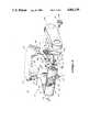
- FIG. 1is an isometric view of the present invention adapted to exercise a knee joint
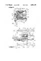
- FIG. 2is an enlarged, fragmentary, isometric view of the present invention shown in FIG. 1 to more specifically illustrate the construction of the fluid cylinder assembly and transmission mechanism;
- FIG. 3is an enlarged, fragmentary, cross-sectional view of the fluid cylinder assembly shown in FIG. 2 and taken substantially along lines 3--3 thereof;
- FIG. 4is another enlarged, fragmentary, cross-sectional view of the fluid cylinder assembly shown in FIG. 2 and taken substantially along lines 4--4 thereof;
- FIG. 5is an enlarged, fragmentary, cross-sectional view of the joint assembly utilized in the apparatus of the present invention and taken substantially along lines 5--5 of FIG. 2;
- FIG. 6is a fragmentary, cross-sectional view of the fluid cylinder assembly shown in FIG. 2 illustrating an alternative embodiment of the present invention
- FIG. 7is a further fragmentary, cross-sectional view of the fluid cylinder assembly shown in FIG. 2 illustrating another preferred embodiment of the present invention
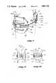
- FIG. 8is a fragmentary, isometric view illustrating an additional embodiment wherein the present invention may be utilized as a simple knee brace
- FIG. 9is a fragmentary, isometric view of yet another preferred embodiment of the present invention.
- FIG. 10is a fragmentary, side elevational view of a further preferred embodiment of the present invention illustrating an alternative construction of the lower cuff assembly.
- FIG. 11is a fragmentary, front elevational view of FIG. 10.
- the exercising apparatus 10includes an articulating frame 12 composed of a pair of flat, laterally, spaced-apart upper angle arms 14a and 14b pivotally pinned to a pair of corresponding spaced-apart lower arms 16a and 16b so as to pivot about a transverse axis 17.
- the axis 17is positioned in approximate alignment with the axis of rotation of the knee by an upper cuff assembly 18 connected to the upper portions of the arms 14a and 14b to encircle the portion of the thigh adjacent the knee and a lower cuff assembly 20 connected to the lower ends of the lower arms 16a and 16b to encircle the calf just below the knee.
- a fluid cylinder assembly 22which is mounted on the upper angle arms 14a and 14b at a location spaced slightly forwardly of the knee to extend alongside the axis of rotation of the knee.
- the cylinder assembly 22includes a piston 24 threadably engaged with an elongated piston rod 26 whereby upon rotation of the piston rod, the piston 24 slides along the interior of an inner cylinder 28.
- a transmission systemtransmits the relative rotational movement between the lower arms 16a and 16b and the upper arms 14a and 14b to the piston rod 26 thereby to actuate the piston 24. This is accomplished through the use of drive pulleys 30 secured to the upper ends of lower arms 16a and 16b, smaller driven pulleys mounted on the outer ends of the piston rod 26 and the drive belts 34 trained around the pulleys 30 and 32 to transmit rotational movement therebetween.
- the upper and lower cuff assemblies 18 and 20are placed around the lower thigh and upper calf of the user to align the pivot axis 17 of the frame 12 with the rotational axis of the knee joint.
- the knee jointis exercised simply by flexing and extending the leg in opposition to the resistance to the relative pivotal movement of the frame 12 generated by the cylinder assembly 22.
- the apparatus 10can be used to exercise the knee during specific exercising regimes or routines; however, perhaps more importantly is also can be worn during normal activities to provide exercise throughout the day whenever the knee is flexed or extended.
- the upper angle arms 14a and 14b of the pivot frame 12include flat, elongate, upwardly extending sections 40, which are attached to the forward and rearward outer, formed shell members 42 and 44, respectively, of the upper cuff assembly 18.
- Arm 14bis fastened to the adjacent "inside" edge portions of the shell members 42 and 44 by conventional fastener members, such as rivets 46.
- the forward shell member 42is attached to arm 14a thereby to enable the shell members to be opened when donning or duffing the apparatus.
- the shell members 42 and 44are formed to cooperatively define circular, frustoconical shape to approximate the shape of the lower thigh of the wearer.
- a series of slots 48 or other type or shape of openingsmay be formed in the shell members 42 and 44.
- Resilient padding 50 and 52is mounted on the inside surfaces of the forward and rearward shell members 42 and 44, respectively, to provide comfort to the wearer and to snugly fit the cuff assembly 18 around the leg.
- the paddingmay be composed of appropriate resilient materials, such as foamed rubber or plastic.
- an air bladdernot shown, may be used in conjunction with or as an alternative to the padding 50 and/or 52.
- the air bladdercould be provided with a standard valve and stem for directing air into and out of the bladder.
- Both the padding 50 and 52 and the air bladderideally are removably secured to the shell members so that they can be sized to accommodate the size and shape of a wearer's leg and also replaced when worn.
- the two shell members 42 and 44 of the upper cuff assembly 18are clamped around the lower thigh of the wearer by a pair of spaced-apart, quick release latch assemblies 58 secured to the outward side edge portions of the forward and rearward shell members 42 and 44.
- the latch assemblies 58may be of any appropriate construction and include a latch or buckle 60 mounted on either the forward or rearward shell member to engage with a corresponding strap 62 mounted on the other shell member.
- the two shell members 42 and 44are flexible enough to enable the upper cuff assembly to be conveniently opened and placed around the thigh when donning apparatus 10 even though the inward or closed side edge portions of the shell members are attached to arm 14b.
- the upper arms 14a and 14balso include elongated, flat, forwardly extending sections 64 disposed in spaced parallel relationship to each other for mounting the cylinder assembly 22 at a location spaced slightly forwardly of the knee. This location is designated as the "extendible" side of the knee joint in that the leg members rotate in this direction about the knee joint as the leg is being extended. For the same reason the opposite side of the leg will be referred to as the "flexural" size.
- An offset bend 66is formed at the juncture of the upper sections 40 and the lower forward sections 64 of the upper arms 14a and 14b to maintain the forward sections 64 in spaced parallel relationship to each other while enabling the upper sections to flare outwardly relative to each other to accommodate the increasing width of the thigh in the direction upwardly from the knee.
- the lower cuff assembly 20is composed of a generally U-shaped, outer shell member 70 pivotally attached to the lower ends of the lower pivot arms 16a and 16b by pivot pins 72 which allow the shell member to pivot somewhat about the lower arms to accommodate the shape of the wearer's leg.
- the U-shaped shell member 70is designed to encircle the rear and side portions of the wearer's leg at the upper portion of the calf.
- a resilient pad 74extends around the inside surface of the shell member 70.
- the lower cuff assembly 20is secured in place by a quick release latch assembly 76 composed of a buckle 78 and a strap 80 which extend forwardly around the lower leg of the wearer.
- a forward pad 82is carried by either the buckle 78 or the strap 80 to bear against the front of the lower leg to distribute the clamping force of the latch assembly about a substantial area of the leg to avoid pinching, bruising or otherwise injuring the leg.
- the forward pad 82is constructed with a contoured outer shell member 84 and an underlying resilient pad 86 preferably formed from foam rubber, foam plastic or other appropriate resilient material.
- shell 84, U-shaped shell member 70 and the forward and rearward shell members 42 and 44 of the upper cuff assembly 20are formed from lightweight, high strength material that is formable or moldable into desired shapes. Examples of such materials might include certain metals, such as aluminum and various plastics, such as polypropylene or ABS.
- the upper angle arms 14a and 14bare pivotally connected to the upper ends of the lower pivot arms 16a and 16b to articulate about axis 17 by a pair of pivot shafts 90 extending through aligned, close-fitting openings formed in the upper and lower arms.
- the pivot shafts 90are formed with enlarged rims 92 that engage within counterbores formed in the upper arms 14a and 14b.
- the pivot shafts 90also extend through the central interiors of cogged drive pulleys 30 positioned between the upper and lower pivot arms.
- the pulleys 30are secured to the upper ends of the lower pivot arms 16a and 16b by fasteners, such as screws 96, extending through close-fitting clearance holes formed in the lower arms to engage into aligned, tapped holes formed in the drive pulleys 30.
- the pivot shafts 90are held in place by snap rings 98 engaged within snap ring grooves 100 formed in the outward end portions of the pivot shafts 90.
- the pivot shafts 90are constructed from relatively large diameters to permit the upper pivot arms 14a and 14b to freely pivot relative to the respective lower pivot arms 16a and 16b while minimizing any relative twisting movement between the pivot arms about axis extending in directions other than along the pivot axis 17.
- drive pulleys 30are disposed in alignment with driven pulleys 32 mounted on the outer end portions of the piston rod 26 that extend outwardly beyond upper arm forward sections 64.
- the drive and driven pulleys 30 and 32are adapted to train with a cog or timing belt 34.
- Such beltshave the advantage that they may be engaged over relatively small diameter pulleys without premature wear due to high flexural stresses, they exhibit very little backlash and they are capable of efficiently transmitting relatively high loads. Nonetheless, other types of belts may be used in place of the cog belt 34 without departing from the scope of the present invention.
- a pair of spaced-apart idler rollers 102 and 104bear against the outward, flat surfaces of each belt 34 to guide the belt, to increase the wrap angle of the belt around the smaller driven pulley 32 and to impose a desired tension on the belt.
- the idler rollers 102 and 104are mounted on pins 106 that project outwardly from the sides of the forward sections 64 of the upper arms 14a and 14b, FIG. 2.
- the idler rollers 102 and 104can be replaced with idler rollers of larger or smaller diameters to increase or decrease, respectively, the tension on the belt 34.
- the idler rollers 102 and 104are formed from a low friction, self-lubricating material, such as nylon.
- Formed covers 108are provided to enclose the pulleys 30 and 32, the belt 34 and the rollers 102 and 104 to protect these components.
- the covers 108extend along the entire lengths of the forward sections 64 of the upper arms 14a and 14b and may be attached to the forward sections by any convenient method. Appropriate slots are provided in the lower rims 109 of the covers to provide clearance for the movement of the upper ends of the lower arms 16a and 16b.
- a piston 24is disposed within the interior of a close-fitting inner or first cylinder 28 and is adapted to slide back and forth along the cylinder by rotation of a piston rod 26.
- the piston rod 26has an enlarged central portion 110 formed with high helix angle external threads to engage with the correspondingly threaded central interior of the piston 24.
- the piston rod 26is supported at its end portions by relatively thick, cylindrically-shaped end caps 112 having a threaded exterior for engaging with mating internal threads formed within the ends of the first or inner cylinder 28.
- the piston rod 26is constructed with reduced diameter end portions 114 that engage through close-fitting central bores 116 formed in the end caps 112.
- Bushings 118are pressed within inner counterbores 120 formed in the end caps 112 to antifrictionally receive the end portions 114 of the piston rod 26.
- Seals 122are pressed into outer counterbores 124 formed in the end caps 112 to seal against the reduced diameter sections 114 of the piston rod.
- Driven pulleys 32are secured to the outward ends of the piston rod reduced diameter sections 114 by any convenient method, such as by the use of roll pins 125 engaged within holes extending diametrically through the driven pulleys and through aligned cross holes formed in the piston rod.
- the piston 24is prevented from rotating relative to the piston rod 26 by a guide rod 126 extending through a close-fitting clearance opening formed in the piston 24 at a location offset in the forward direction (relative to apparatus 10) from the central bore of the piston through which the rod 26 extends.
- the ends of the guide rod 126are engaged with aligned bores extending through end caps 112.
- the piston 24is constructed with a central groove 130 extending around the outer circumference of the piston for reception of a seal 132 to minimize the amount of fluid that leaks past the piston as it travels back and forth along the cylinder 28.
- the seal 132is coated with a low friction material, such as Teflon®.
- the seal 132is loaded against the cylinder 28 by an O-ring 134 which is positioned within the groove 130 beneath the seal.
- An annular chamber 140is formed around the outer circumference of the inner cylinder 28 by an outer cylinder 142 having an inside diameter slightly larger than the outside diameter of the inner cylinder.
- a radially, outwardly extending shoulder 144is formed at each end of the inner cylinder 28 to closely fit within the inside diameter of the outer cylinder 142, thereby to space the outer and inner cylinders relative to each other.
- An O-ring seal 146is seated within a groove 148 formed within each shoulder 144, thereby to prevent the leakage of fluid between the inner and outer cylinders.
- the fluid cylinder assembly 22is mounted on the forward ends of arm sections 64 by a plurality of threaded fasteners 149 which extend through clearance holes formed in the forward sections 64 to engage with aligned, tapped, blind holes formed in the cylinder end caps 112.
- the forward ends of the arm sections 64are shaped and sized to bear against the ends of the inner and outer cylinders 28 and 142. It will be appreciated that by this construction the cylinder assembly 22 serves as a structural component of frame 12 to enhance rigidity and structural integrity for the frame.
- Fluid cylinder 22is of the double-acting type and, thus, as piston 24 slides along cylinder 28, the fluid in front of the approaching piston is routed through an end cap 112 to chamber 140 while at the same time fluid from the chamber 140 is routed through the opposite end cap 112 and into the cylinder 128 at the back side of the piston.
- the end caps 112each include a fluid exit passageway 150 having a longitudinal section 152 in communication with the interior of piston 28 and a larger diameter radial section 154 in communication with an aligned opening 156 formed in the inner cylinder 128.
- the smaller diameter longitudinal section 152 of the passageway 150serves as a restriction orifice for the fluid passing through the passageway.
- the exit passageway at the intersection of the longitudinal and radial sections 152 and 154,is formed as a longitudinal, larger diameter section 158 to receive the pointed tip 160 of a needle valve 162.
- the needle valveincludes a threaded shank section 164 that engages with corresponding threads formed in the end cap.
- the needle valvealso includes a pair of O-ring grooves 166 located on the shank portion of the needle valve opposite tip 160 (i.e., outwardly of threads 164) for reception of a pair of closefitting O-rings 168 which minimize the possibility that fluid will leak past the needle valve.
- the needle valvealso includes a distal end section 170 that extends outwardly from the end cap 112 through a clearance opening formed in the forward end of each arm section 64 to receive a knob 172 which may be manually rotated to adjust the engagement of the needle valve 162 within fluid passageway 158.
- a threaded hardware memberextends through a central clearance opening formed in the knob 172 to engage into the threaded interior of end section 170 to attach the knob to the end section.
- the end caps 112also include check valves 178 to allow the fluid in the chamber 140 to flow into the interior of the inner cylinder 28 as the piston 24 is moving away from the check valve while preventing the fluid from flowing in the opposite direction as the piston is moving toward the check valve.
- Each of the check valves 178includes a flow passageway 180 in communication with the interior of cylinder 28 and also in communication with a radial opening 182 extending through the wall of inner cylinder 28 to interconnect the passageway 180 with the chamber 140.
- the check valve 178further includes a ball 182 resiliently loaded by spring 184 against the reduced diameter section 188 of passageway 180. It will be appreciated that ball 184 only permits fluid to flow from chamber 140 into cylinder 82 and not vice versa.
- exercise apparatus 10 of the present inventionmay be conveniently adjusted to selectively and independently vary the level of effort required to flex the leg and extend the leg. This is important in that the muscles used to extend the leg are substantially stronger than those used to flex the leg.
- This dual adjustability capabilityis made possible by utilizing an adjustable needle valve 162 in conjunction with each of the two cylinder assembly end caps 112.
- the needle valves 162vary the effective size of the orifices defined by the longitudinal sections 152 of exit passageways 150 by simply rotating knobs 172 attached to the outer ends of the needle valves 162.
- the needle valves 162provide a dynamic, variable level of resistance to the extension and flexion of the knee joint so that the faster the joint is extended or flexed, the higher the level of resistance to movement experienced by the joint. This results because as the joint is extended or flexed at a faster speed, the rotational speed of the upper angle arms 14a and 14b increases relative to the lower arms 16a and 16b causing drive pulley 30 to rotate faster, which in turn increases the rotational speed of piston rod 26, which in turn induces the piston rod 24 to slide at a faster speed within cylinder 28.
- needle valves 162may be replaced with a rotatable orifice plate, not shown, having a plurality of various diameter orifice openings spaced apart from each other about the center of the orifice plate and in alignment with the fluid exit passageway 150.
- the orifice platemay be rotated about its center to place an orifice of a desired size in registry with the passageway 150 thereby to impose a selected level of resistance to the extension and flexion of the knee joint.
- FIG. 6illustrates an alternative preferred embodiment of the present invention wherein the needle valve 162 illustrated in FIG. 3 is replaced with a spring-loaded ball valve 200 having a ball 202 nominally urged against orifice 152' by a compression spring 204 which is forced against the ball by a threaded shaft 206.
- a knob 172is attached to the outer end of the shaft 206 by a screw 174.
- the valve 200is designed to utilize the apparatus 10 as an isotonic (constant load) device.
- the fluid from the cylinder 28' flowing through the orifice 152'is correspondingly increased or decreased so that the apparatus 10 provides a constant resistance to the flexing or extending movement of the leg.
- the ball 202is retracted against the spring 204 to increase the effective area of the orifice 152', and conversely when the flow of fluid through the orifice is decreased, the force on the ball 202 by the fluid flowing through the orifice is reduced thereby causing the ball to extend forwardly under the urging force of the spring 204 to reduce the effective area of the orifice 152'.
- the desired level of resistance to the movement of the body jointis selectively controlled by rotation of the valve shaft 206 to advance or retract the shaft to in turn increase and decrease, respectively, the load applied to ball 202 by the spring 204.
- a pressure compensated flow control valve 220is utilized to permit the apparatus 10 to pivot at a constant speed about axis 17 even though the wearer of the apparatus expends different levels of effort in extending or flexing the leg.
- Valve 220is integrated into end cap 112" to replace the needle valve 162 shown in FIG. 3.
- the valveincludes an inlet 222 in communication with the interior of cylinder 28" and an outlet 224 in communication with an opening 156" formed in the wall of cylinder 28" leading to the annular chamber 140".
- a metering needle 226is disposed across the path 227 of fluid flowing through valve 220 to control the maximum flow rate of fluid through the valve.
- a compensating spool 228is disposed within a cavity 229 extending transversely across the fluid flow path 227.
- One end 230 of spool 228bears against a compression spring 232 which extends across a feedback passageway 234 which is in fluid flow communication with outlet 224.
- a second feedback passageway 236is in communication with the opposite end 238 of the spool 228 to sense the fluid pressure immediately upstream of needle valve 226.
- the position of the compensating spool 228varies in response to the pressure of the fluid at inlet 222 so that with the higher the pressure of the fluid at the inlet, the valve shifts to reduce the effective area of the fluid path and with a reduction in the pressure of the fluid at inlet 222 the compensating spool 228 moves in the opposite direction to increase the effective area of the fluid path through the valve so that a substantially constant volume of fluid is discharged at outlet 224.
- Pressure-compensating flow control valves, such as valve 220are standard articles of commerce. As noted above, in certain types of therapeutic treatments for injuries to body joints, the joint is exercised by flexion and extension at a constant speed. Apparatus 10 may be adapted for this type of treatment by employing the pressure compensated flow control valve 220.
- the fluid cylinder assembly 22 shown in FIGS. 1-4is replaced by a pivot joint 250 to enable the apparatus 10 to be employed as a simple knee brace.
- the lower end of the upper pivot arm 252, corresponding to arm 14,is detachably connected to a stub member 254 by screws 266 extending through clearance holes 268 formed in the upper shank portion of the stub member that overlaps the lower end of the upper arm 252 to engage within aligned threaded holes formed in the upper arm.
- the stub memberalso includes an enlarged, circular, lower head portion that bears against one side of a circular spacer 256 which is used to replace drive gear 30.
- the pivot joint 250also has a lower pivot arm 258 corresponding to arm 16 which is detachably connectible to a stub member 260 with screws 270.
- the stub member 260includes an enlarged, circular head portion to abut against the opposite side of spacer 256.
- the pivot joint 250utilizes the same pivot shaft 90 shown in FIG. 5, as well as the same snap ring 98 to maintain the shaft in engagement with the stub members 254 and 260 and the spacer 256.
- the fluid cylinder assembly 26 and its associated drive mechanismis mounted on a subframe having stub members that are detachably engageable with the upper arm 252 and the lower arm 260 so that the subassembly may be simply substituted for pivot joint 250 as desired.
- the distance between the upper cuff assembly 18 and the pivot axis 17may be adjusted by simply removing screws 266 and then reattaching the stub member 254 to upper pivot arm 254 reengaging the screws in another set of tapped holes 268 formed in upper arm 252.
- the distance between the lower cuff assembly 20 and the pivot axis 17may be varied by removing lower screws 270 and then reattaching the stub member 260 to the lower pivot arm 258 by reengaging the screws into a different set of tapped holes 272 formed in the lower arm.
- a lower cuff assembly 20'is attached to the lower end of pivot arms 280a and 280b so as to permit the cuff assembly to "float" toward and away from the pivot axis 17 as the body joint is being flexed or extended.
- This embodiment of the present inventionaccommodates the fact that a knee joint approximates but is not exactly analogous to a simple hinge joint and also that it may not be possible to always align the pivot axis 17 of apparatus 10 at exactly the pivot axis of the knee joint. As such, it may be desirable to allow the upper and lower cuff assemblies to freely move toward and away from each other as the apparatus 10 is being utilized.
- the lower cuff assembly 20'is attached to the lower ends of the pivot arms 280a and 280b by pins 282 which extends through close-fitting, vertically elongated slots 284 formed in the lower ends of the arms.
- the pins 282are formed with enlarged head portions 286 to prevent the pin from disengaging from the arms 280a and 280b.
- the embodiment of the present invention shown in FIG. 9is substantially the same as shown in FIGS. 1-5.
- FIGS. 10 and 11illustrate a further preferred embodiment of the present invention illustrating an alternative construction of the cuff assembly 20 shown in FIG. 1 and the cuff assembly 20' shown in FIG. 9.
- the cuff assembly 20" shown in FIGS. 10 and 11includes a formed, forward shell member shaped to encircle the forward portion of the calf.
- the side portions of the forward shell memberare pivotally attached to the lower ends of the lower pivot arms 16a' and 16b' by pivot pins 302 which extend through close-fitting, vertically elongated slots 304 formed in the lower ends of the arms 16a' and 16b'.
- the pins 302are formed with enlarged head portions 306 to prevent the pins from disengaging from the arms 16a' and 16b'.
- the lower cuff assembly 20"also includes a rearward, formed shell member 308 for encircling the rearward portion of the lower thigh of the wearer.
- the "inside" edge portion of the rearward shell member 308is hinged to the adjacent edge portion of the forward shell member with a flexible hinge member 310 which is secured to the two shell members by any convenient method.
- a quick release latch assembly 312is secured to the outward side edge portions of the forward and rearward shell members 308.
- the latch assembly 312may be of any appropriate construction and includes a latch or buckle 314 mounted on either the forward or rearward shell member to engage with a corresponding strap 316 mounted on the other shell member.
- Resilient padding 320 and 322is mounted on the inside surfaces of the shell members 300, 308, respectively, to provide comfort to the wearer and to snugly fit the cuff assembly 18 around the leg.
- the paddingmay be composed of appropriate resilient materials, such as foam rubber or plastic.
- an air bladdernot shown, may be used. The air bladder could be provided with a standard valve and stem for directing air into and out of the bladder.
- the wearermay conveniently gain “rear entry” to the apparatus.
- the latch assemblies 58 and 312may be detached so that the rear shell members 44 and 308, respectively are pivoted into open position. Thereafter, the apparatus may be simply laid over the forward portion of the wearer's leg and then the rear shell members 44 and 308 closed around the rearward portions of the legs and conveniently latched to the corresponding forward shell members 42 and 300, respectively.
- This constructioneliminates the need to "pull” or "draw” the apparatus up the leg from the foot.
- the width of apparatus 10is kept to a minimum to thus avoid interference with other body members. Also, by locating the cylinder assembly 22 on the extendible side of the knee joint, the cylinder assembly is out of the way and does not hamper the ability of the knee joint to be fully flexed.
- the apparatus 10may be utilized not only when performing specific exercises, but also during regular daily activities, whether at home or at work. As such, a specific time period does not have to be devoted to exercising a desired body joint, but rather the joint is exercised during normal body movements.
- the present inventionmay be embodied in forms other than those specifically disclosed above and may be adapted for use with other body joints, such as the ankle or wrist joints, without departing from the spirit or scope of the present invention.
- the particular embodiments of the exercise apparatus 10 set forth above,are therefore to be considered in all respects as illustrative and not restrictive.
- the scope of the present inventionis as set forth in the appended claims rather than being limited to the examples of the apparatus 10 set forth in the foregoing description.
Landscapes
- Health & Medical Sciences (AREA)
- Life Sciences & Earth Sciences (AREA)
- Biophysics (AREA)
- Orthopedic Medicine & Surgery (AREA)
- General Health & Medical Sciences (AREA)
- Physical Education & Sports Medicine (AREA)
- Orthopedics, Nursing, And Contraception (AREA)
Abstract
Description
Claims (43)
Priority Applications (1)
| Application Number | Priority Date | Filing Date | Title |
|---|---|---|---|
| US07/127,113US4801138A (en) | 1987-12-01 | 1987-12-01 | Wearable apparatus for exercising body joints |
Applications Claiming Priority (1)
| Application Number | Priority Date | Filing Date | Title |
|---|---|---|---|
| US07/127,113US4801138A (en) | 1987-12-01 | 1987-12-01 | Wearable apparatus for exercising body joints |
Publications (1)
| Publication Number | Publication Date |
|---|---|
| US4801138Atrue US4801138A (en) | 1989-01-31 |
Family
ID=22428373
Family Applications (1)
| Application Number | Title | Priority Date | Filing Date |
|---|---|---|---|
| US07/127,113Expired - LifetimeUS4801138A (en) | 1987-12-01 | 1987-12-01 | Wearable apparatus for exercising body joints |
Country Status (1)
| Country | Link |
|---|---|
| US (1) | US4801138A (en) |
Cited By (76)
| Publication number | Priority date | Publication date | Assignee | Title |
|---|---|---|---|---|
| US4961416A (en)* | 1989-06-12 | 1990-10-09 | Orthopedic Systems, Inc. | Knee brace |
| US4986537A (en)* | 1990-01-22 | 1991-01-22 | Orta Frank D | Sidewinder exerciser |
| US5052379A (en)* | 1989-04-27 | 1991-10-01 | Soma Dynamics Corporation | Combination brace and wearable exercise apparatus for body joints |
| US5100403A (en)* | 1990-06-08 | 1992-03-31 | Smith & Nephew Richards, Inc. | Dynamic elbow support |
| US5102411A (en)* | 1990-06-08 | 1992-04-07 | Hotchkiss Robert N | Dynamic elbow support |
| US5116296A (en)* | 1991-04-26 | 1992-05-26 | Medmetric Corporation | Isometric leg muscle ergometer |
| US5117814A (en)* | 1990-03-16 | 1992-06-02 | Q-Motus, Inc. | Dynamic splint |
| US5190511A (en)* | 1991-09-03 | 1993-03-02 | Petree Larry G | Exercise equipment employing fluid resistance suitable for use in spacecraft and other low gravity environments |
| US5236333A (en)* | 1992-01-29 | 1993-08-17 | Barba Jr Alfonso | Leg exerciser |
| US5358468A (en)* | 1993-03-26 | 1994-10-25 | Matthew C. Longo | Adjustable resistance knee rehabilitating and strengthening apparatus |
| US5395304A (en)* | 1993-04-06 | 1995-03-07 | Tarr; Stephen E. | Active pivot joint device |
| WO1995006499A1 (en)* | 1993-09-02 | 1995-03-09 | Bauerfeind Gmbh & Co. | Therapeutic orthosis |
| DE4400820A1 (en)* | 1994-01-13 | 1995-07-20 | Lothar Stiklorus | Leg fitted running and jumping aid |
| US5472409A (en)* | 1994-09-23 | 1995-12-05 | Hoy; David J. | Adjustable brace |
| US5472412A (en)* | 1994-04-05 | 1995-12-05 | Mauch Laboratories, Inc. | Limb brace with adjustable hydraulic resistance unit |
| US5626537A (en)* | 1993-11-23 | 1997-05-06 | Danyo; J. Joseph | Exercise compliance apparatus and method |
| US5711746A (en)* | 1996-03-11 | 1998-01-27 | Lord Corporation | Portable controllable fluid rehabilitation devices |
| US5865714A (en)* | 1997-07-03 | 1999-02-02 | Marlowe; Dennis | Arm exercise device |
| US5929782A (en)* | 1990-02-21 | 1999-07-27 | Stark; John G. | Communication system for an instrumented orthopedic restraining device and method therefor |
| US5954621A (en)* | 1993-07-09 | 1999-09-21 | Kinetecs, Inc. | Exercise apparatus and technique |
| US5980435A (en)* | 1993-07-09 | 1999-11-09 | Kinetecs, Inc. | Methods of therapy or controlled exercise using a jointed brace |
| USD451603S1 (en) | 2000-06-15 | 2001-12-04 | Dj Orthopedics, Llc | Electronic display device |
| US20020029784A1 (en)* | 1999-06-11 | 2002-03-14 | Izex Technologies, Inc. | Database management for an orthopedic treatment system |
| US6361448B1 (en)* | 1999-12-28 | 2002-03-26 | Mckeon Brian P. | Apparatus and method for controlling and stabilizing the swing mechanics of a golfer |
| US6436058B1 (en) | 2000-06-15 | 2002-08-20 | Dj Orthopedics, Llc | System and method for implementing rehabilitation protocols for an orthopedic restraining device |
| US6515593B1 (en) | 1995-02-15 | 2003-02-04 | Izex Technologies, Inc. | Communication system for an instrumented orthopedic restraining device and method therefor |
| US6827670B1 (en) | 1999-10-11 | 2004-12-07 | Izex Technologies, Inc. | System for medical protocol management |
| US20040260219A1 (en)* | 2003-06-19 | 2004-12-23 | Bernadette Jestrabek-Hart | Orthopedic device allows kneeling without contact to the knee and protects other joints |
| US6872187B1 (en) | 1998-09-01 | 2005-03-29 | Izex Technologies, Inc. | Orthoses for joint rehabilitation |
| US20050107726A1 (en)* | 1999-08-25 | 2005-05-19 | Oyen Duane P. | Remote monitoring of an instrumented orthosis |
| US20050113652A1 (en)* | 1999-06-23 | 2005-05-26 | Izex Technologies, Inc. | Remote psychological evaluation |
| US20050148918A1 (en)* | 2004-01-06 | 2005-07-07 | Nathanson Jeremy J. | Orthopedic brace suspension system |
| US20060135902A1 (en)* | 2004-12-22 | 2006-06-22 | Ossur Hf | Knee brace and method for securing the same |
| US20060135900A1 (en)* | 2004-12-22 | 2006-06-22 | Ossur Hf | Knee brace and method for securing the same |
| US20060271112A1 (en)* | 2004-11-15 | 2006-11-30 | Martinson James B | Instrumented orthopedic and other medical implants |
| US20070161479A1 (en)* | 2006-01-10 | 2007-07-12 | Harris Donald T | Knee-stretching Device and Treatment Methods |
| US20080195005A1 (en)* | 2007-02-14 | 2008-08-14 | Horst Robert W | Methods and devices for deep vein thrombosis prevention |
| US20090036804A1 (en)* | 2002-11-25 | 2009-02-05 | Horst Robert W | Power regeneration in active muscle assistance device and method |
| US7507215B2 (en) | 2005-07-08 | 2009-03-24 | Jri Development Group, Llc | Orthotic brace |
| US20090306548A1 (en)* | 2008-06-05 | 2009-12-10 | Bhugra Kern S | Therapeutic method and device for rehabilitation |
| US20100038983A1 (en)* | 2008-08-14 | 2010-02-18 | Kern Bhugra | Actuator system with a motor assembly and latch for extending and flexing a joint |
| US20100094189A1 (en)* | 2004-12-22 | 2010-04-15 | Arni Thor Ingimundarson | Orthopedic device |
| US20100113994A1 (en)* | 2004-12-22 | 2010-05-06 | Arni Thor Ingimundarson | Orthopedic device |
| US20100198124A1 (en)* | 2009-01-30 | 2010-08-05 | Kern Bhugra | System and method for controlling the joint motion of a user based on a measured physiological property |
| US20100204620A1 (en)* | 2009-02-09 | 2010-08-12 | Smith Jonathan A | Therapy and mobility assistance system |
| US20100211355A1 (en)* | 2009-02-09 | 2010-08-19 | Horst Robert W | Foot pad device and method of obtaining weight data |
| US20100217169A1 (en)* | 2004-12-22 | 2010-08-26 | Arni Thor Ingimundarson | Spacer element for use in an orthopedic or prosthetic device |
| US20100222151A1 (en)* | 2009-02-27 | 2010-09-02 | Mcnamara Thomas | Apparatus for maintaining an angular position of a leg |
| US20100331750A1 (en)* | 2004-12-22 | 2010-12-30 | Arni Thor Ingimundarson | Orthopedic device |
| US20110184326A1 (en)* | 2004-12-22 | 2011-07-28 | Arni Thor Ingimundarson | Knee brace and method for securing the same |
| US20110224585A1 (en)* | 2010-03-15 | 2011-09-15 | Jacob Randy Hall | Knee rehabilitation device |
| US8241234B2 (en) | 2004-12-22 | 2012-08-14 | Ossur Hf | Knee brace and method for securing the same |
| US8409121B1 (en)* | 2007-12-05 | 2013-04-02 | Waleed Al-Oboudi | Dynamic manual elbow and knee flexion-extension assist device |
| US8771210B2 (en) | 2008-02-08 | 2014-07-08 | Alterg, Inc. | Multi-fit orthotic and mobility assistance apparatus |
| US8784475B2 (en) | 2004-11-15 | 2014-07-22 | Izex Technologies, Inc. | Instrumented implantable stents, vascular grafts and other medical devices |
| US9265645B2 (en) | 2004-12-22 | 2016-02-23 | Ossur Hf | Orthotic device and method for securing the same |
| US9358146B2 (en) | 2013-01-07 | 2016-06-07 | Ossur Hf | Orthopedic device and method for securing the same |
| US9364365B2 (en) | 2013-01-31 | 2016-06-14 | Ossur Hf | Progressive force strap assembly for use with an orthopedic device |
| US9375341B2 (en) | 2013-01-31 | 2016-06-28 | Ossur Hf | Orthopedic device having detachable components for treatment stages and method for using the same |
| US9474334B2 (en) | 2012-11-13 | 2016-10-25 | Ossur Hf | Fastener member for affixation to a structure in an orthopedic device and method for securing the same |
| US9498025B2 (en) | 2013-04-08 | 2016-11-22 | Ossur Hf | Strap attachment system for orthopedic device |
| US9889058B2 (en) | 2013-03-15 | 2018-02-13 | Alterg, Inc. | Orthotic device drive system and method |
| US10052221B2 (en) | 2015-01-06 | 2018-08-21 | Ossur Iceland Ehf | Orthopedic device for treating osteoarthritis of the knee |
| USD882803S1 (en) | 2018-10-08 | 2020-04-28 | Ossur Iceland Ehf | Orthopedic shell |
| USD888258S1 (en) | 2018-10-08 | 2020-06-23 | Ossur Iceland Ehf | Connector assembly |
| US10702740B2 (en) | 2018-09-14 | 2020-07-07 | Ts Medical Llc | Portable devices for exercising muscles in the ankle, foot, and/or leg, and related methods |
| USD908458S1 (en) | 2018-10-08 | 2021-01-26 | Ossur Iceland Ehf | Hinge cover |
| US11234850B2 (en) | 2016-06-06 | 2022-02-01 | Ossur Iceland Ehf | Orthopedic device, strap system and method for securing the same |
| USD961023S1 (en) | 2020-02-12 | 2022-08-16 | TS Medical, LLC | Excercise device |
| US11547589B2 (en) | 2017-10-06 | 2023-01-10 | Ossur Iceland Ehf | Orthopedic device for unloading a knee |
| US11638852B2 (en) | 2018-04-06 | 2023-05-02 | TS Medical, LLC | Portable devices for exercising muscles in the ankle, foot, and/or leg, and related methods |
| US11850175B2 (en) | 2016-06-06 | 2023-12-26 | Ossur Iceland Ehf | Orthopedic device, strap system and method for securing the same |
| US11872150B2 (en) | 2020-12-28 | 2024-01-16 | Ossur Iceland Ehf | Sleeve and method for use with orthopedic device |
| USD1012207S1 (en) | 2020-08-12 | 2024-01-23 | TS Medical, LLC | Exercise device |
| US11904204B2 (en) | 2018-02-26 | 2024-02-20 | Ts Medical Llc | Devices and methods for exercising an ankle, foot, and/or leg |
| US11918504B1 (en) | 2019-11-13 | 2024-03-05 | Preferred Prescription, Inc. | Orthotic device to prevent hyperextension |
Citations (4)
| Publication number | Priority date | Publication date | Assignee | Title |
|---|---|---|---|---|
| US3683897A (en)* | 1968-12-05 | 1972-08-15 | Flowtron Aire Ltd | Apparatus for moving or activating parts of the body |
| US3976057A (en)* | 1974-12-23 | 1976-08-24 | Clarence F. Bates | Joint flexing apparatus |
| US4520804A (en)* | 1981-08-04 | 1985-06-04 | Digeorge Michael A | Double-locking ratchet for orthopedic brace |
| US4651719A (en)* | 1985-01-22 | 1987-03-24 | Danninger Medical Technology, Inc. | Continuous passive motion shoulder unit |
- 1987
- 1987-12-01USUS07/127,113patent/US4801138A/ennot_activeExpired - Lifetime
Patent Citations (4)
| Publication number | Priority date | Publication date | Assignee | Title |
|---|---|---|---|---|
| US3683897A (en)* | 1968-12-05 | 1972-08-15 | Flowtron Aire Ltd | Apparatus for moving or activating parts of the body |
| US3976057A (en)* | 1974-12-23 | 1976-08-24 | Clarence F. Bates | Joint flexing apparatus |
| US4520804A (en)* | 1981-08-04 | 1985-06-04 | Digeorge Michael A | Double-locking ratchet for orthopedic brace |
| US4651719A (en)* | 1985-01-22 | 1987-03-24 | Danninger Medical Technology, Inc. | Continuous passive motion shoulder unit |
Cited By (130)
| Publication number | Priority date | Publication date | Assignee | Title |
|---|---|---|---|---|
| US5052379A (en)* | 1989-04-27 | 1991-10-01 | Soma Dynamics Corporation | Combination brace and wearable exercise apparatus for body joints |
| US4961416A (en)* | 1989-06-12 | 1990-10-09 | Orthopedic Systems, Inc. | Knee brace |
| US4986537A (en)* | 1990-01-22 | 1991-01-22 | Orta Frank D | Sidewinder exerciser |
| US5929782A (en)* | 1990-02-21 | 1999-07-27 | Stark; John G. | Communication system for an instrumented orthopedic restraining device and method therefor |
| US5117814A (en)* | 1990-03-16 | 1992-06-02 | Q-Motus, Inc. | Dynamic splint |
| US5100403A (en)* | 1990-06-08 | 1992-03-31 | Smith & Nephew Richards, Inc. | Dynamic elbow support |
| US5102411A (en)* | 1990-06-08 | 1992-04-07 | Hotchkiss Robert N | Dynamic elbow support |
| US5116296A (en)* | 1991-04-26 | 1992-05-26 | Medmetric Corporation | Isometric leg muscle ergometer |
| US5190511A (en)* | 1991-09-03 | 1993-03-02 | Petree Larry G | Exercise equipment employing fluid resistance suitable for use in spacecraft and other low gravity environments |
| US5236333A (en)* | 1992-01-29 | 1993-08-17 | Barba Jr Alfonso | Leg exerciser |
| US5358468A (en)* | 1993-03-26 | 1994-10-25 | Matthew C. Longo | Adjustable resistance knee rehabilitating and strengthening apparatus |
| US5395304A (en)* | 1993-04-06 | 1995-03-07 | Tarr; Stephen E. | Active pivot joint device |
| US5980435A (en)* | 1993-07-09 | 1999-11-09 | Kinetecs, Inc. | Methods of therapy or controlled exercise using a jointed brace |
| US5954621A (en)* | 1993-07-09 | 1999-09-21 | Kinetecs, Inc. | Exercise apparatus and technique |
| WO1995006499A1 (en)* | 1993-09-02 | 1995-03-09 | Bauerfeind Gmbh & Co. | Therapeutic orthosis |
| US5626537A (en)* | 1993-11-23 | 1997-05-06 | Danyo; J. Joseph | Exercise compliance apparatus and method |
| DE4400820A1 (en)* | 1994-01-13 | 1995-07-20 | Lothar Stiklorus | Leg fitted running and jumping aid |
| DE4400820C2 (en)* | 1994-01-13 | 1998-09-10 | Lothar Stiklorus | Jump booster |
| US5472412A (en)* | 1994-04-05 | 1995-12-05 | Mauch Laboratories, Inc. | Limb brace with adjustable hydraulic resistance unit |
| US5472409A (en)* | 1994-09-23 | 1995-12-05 | Hoy; David J. | Adjustable brace |
| US6515593B1 (en) | 1995-02-15 | 2003-02-04 | Izex Technologies, Inc. | Communication system for an instrumented orthopedic restraining device and method therefor |
| US5711746A (en)* | 1996-03-11 | 1998-01-27 | Lord Corporation | Portable controllable fluid rehabilitation devices |
| US5865714A (en)* | 1997-07-03 | 1999-02-02 | Marlowe; Dennis | Arm exercise device |
| US6872187B1 (en) | 1998-09-01 | 2005-03-29 | Izex Technologies, Inc. | Orthoses for joint rehabilitation |
| US8678979B2 (en) | 1998-09-01 | 2014-03-25 | Izex Technologies, Inc. | Remote monitoring of a patient |
| US20070155588A1 (en)* | 1998-09-01 | 2007-07-05 | Izex Technologies, Inc. | Remote monitoring of a patient |
| US9230057B2 (en) | 1998-09-01 | 2016-01-05 | Izex Technologies, Inc. | Remote monitoring of a patient |
| US20020029784A1 (en)* | 1999-06-11 | 2002-03-14 | Izex Technologies, Inc. | Database management for an orthopedic treatment system |
| US8790258B2 (en) | 1999-06-23 | 2014-07-29 | Izex Technologies, Inc. | Remote psychological evaluation |
| US20100121160A1 (en)* | 1999-06-23 | 2010-05-13 | Izex Technologies, Inc. | Remote psychological evaluation |
| US7416537B1 (en) | 1999-06-23 | 2008-08-26 | Izex Technologies, Inc. | Rehabilitative orthoses |
| US20050113652A1 (en)* | 1999-06-23 | 2005-05-26 | Izex Technologies, Inc. | Remote psychological evaluation |
| US20050107726A1 (en)* | 1999-08-25 | 2005-05-19 | Oyen Duane P. | Remote monitoring of an instrumented orthosis |
| US6827670B1 (en) | 1999-10-11 | 2004-12-07 | Izex Technologies, Inc. | System for medical protocol management |
| US20040249675A1 (en)* | 1999-10-11 | 2004-12-09 | Izex Technology, Inc. | System for medical protocol management |
| US6361448B1 (en)* | 1999-12-28 | 2002-03-26 | Mckeon Brian P. | Apparatus and method for controlling and stabilizing the swing mechanics of a golfer |
| US6436058B1 (en) | 2000-06-15 | 2002-08-20 | Dj Orthopedics, Llc | System and method for implementing rehabilitation protocols for an orthopedic restraining device |
| USD451603S1 (en) | 2000-06-15 | 2001-12-04 | Dj Orthopedics, Llc | Electronic display device |
| US8679040B2 (en) | 2002-11-25 | 2014-03-25 | Alterg, Inc. | Intention-based therapy device and method |
| US20100318006A1 (en)* | 2002-11-25 | 2010-12-16 | Horst Robert W | Power regeneration in active muscle assistance device and method |
| US20090036804A1 (en)* | 2002-11-25 | 2009-02-05 | Horst Robert W | Power regeneration in active muscle assistance device and method |
| US20040260219A1 (en)* | 2003-06-19 | 2004-12-23 | Bernadette Jestrabek-Hart | Orthopedic device allows kneeling without contact to the knee and protects other joints |
| US6913583B2 (en)* | 2003-06-19 | 2005-07-05 | Creations By B J H, Llc | Orthopedic device allows kneeling without contacting knee |
| US20050148918A1 (en)* | 2004-01-06 | 2005-07-07 | Nathanson Jeremy J. | Orthopedic brace suspension system |
| US7967765B2 (en) | 2004-01-06 | 2011-06-28 | Djo, Llc | Orthopedic brace suspension system |
| US8740879B2 (en) | 2004-11-15 | 2014-06-03 | Izex Technologies, Inc. | Instrumented orthopedic and other medical implants |
| US8491572B2 (en) | 2004-11-15 | 2013-07-23 | Izex Technologies, Inc. | Instrumented orthopedic and other medical implants |
| US8784475B2 (en) | 2004-11-15 | 2014-07-22 | Izex Technologies, Inc. | Instrumented implantable stents, vascular grafts and other medical devices |
| US20060271112A1 (en)* | 2004-11-15 | 2006-11-30 | Martinson James B | Instrumented orthopedic and other medical implants |
| US8241234B2 (en) | 2004-12-22 | 2012-08-14 | Ossur Hf | Knee brace and method for securing the same |
| US8425441B2 (en) | 2004-12-22 | 2013-04-23 | Ossur Hf | Spacer element for use in an orthopedic or prosthetic device |
| US9814615B2 (en) | 2004-12-22 | 2017-11-14 | Ossur Hf | Orthopedic device |
| US11129740B2 (en) | 2004-12-22 | 2021-09-28 | Ossur Hf | Orthopedic device |
| US20100217169A1 (en)* | 2004-12-22 | 2010-08-26 | Arni Thor Ingimundarson | Spacer element for use in an orthopedic or prosthetic device |
| US11529250B2 (en) | 2004-12-22 | 2022-12-20 | Ossur Hf | Orthopedic device |
| US7794418B2 (en)* | 2004-12-22 | 2010-09-14 | Ossur Hf | Knee brace and method for securing the same |
| US20100113994A1 (en)* | 2004-12-22 | 2010-05-06 | Arni Thor Ingimundarson | Orthopedic device |
| US20100331750A1 (en)* | 2004-12-22 | 2010-12-30 | Arni Thor Ingimundarson | Orthopedic device |
| US7896827B2 (en) | 2004-12-22 | 2011-03-01 | Ossur Hf | Knee brace and method for securing the same |
| US20100094189A1 (en)* | 2004-12-22 | 2010-04-15 | Arni Thor Ingimundarson | Orthopedic device |
| US20110184326A1 (en)* | 2004-12-22 | 2011-07-28 | Arni Thor Ingimundarson | Knee brace and method for securing the same |
| US20110218471A1 (en)* | 2004-12-22 | 2011-09-08 | Arni Thor Ingimundarson | Spacer element for prosthetic and orthotic devices |
| US8016781B2 (en) | 2004-12-22 | 2011-09-13 | Ossur Hf | Knee brace and method for securing the same |
| US9265645B2 (en) | 2004-12-22 | 2016-02-23 | Ossur Hf | Orthotic device and method for securing the same |
| US8216170B2 (en) | 2004-12-22 | 2012-07-10 | Ossur Hf | Orthopedic device |
| US20100081979A1 (en)* | 2004-12-22 | 2010-04-01 | Arni Thor Ingimundarson | Knee brace and method for securing the same |
| US8257293B2 (en) | 2004-12-22 | 2012-09-04 | Ossur Hf | Knee brace and method for securing the same |
| US8267879B2 (en) | 2004-12-22 | 2012-09-18 | Ossur Hf | Spacer element for prosthetic and orthotic devices |
| US20060135902A1 (en)* | 2004-12-22 | 2006-06-22 | Ossur Hf | Knee brace and method for securing the same |
| US8328746B2 (en) | 2004-12-22 | 2012-12-11 | Ossur Hf | Knee brace and method for securing the same |
| US9220622B2 (en) | 2004-12-22 | 2015-12-29 | Ossur Hf | Orthopedic device |
| US8864692B2 (en) | 2004-12-22 | 2014-10-21 | Ossur Hf | Knee brace and method for securing the same |
| US20060135900A1 (en)* | 2004-12-22 | 2006-06-22 | Ossur Hf | Knee brace and method for securing the same |
| US8585623B2 (en) | 2004-12-22 | 2013-11-19 | Ossur Hf | Orthopedic device |
| US7507215B2 (en) | 2005-07-08 | 2009-03-24 | Jri Development Group, Llc | Orthotic brace |
| US20070161479A1 (en)* | 2006-01-10 | 2007-07-12 | Harris Donald T | Knee-stretching Device and Treatment Methods |
| US9474673B2 (en) | 2007-02-14 | 2016-10-25 | Alterg, Inc. | Methods and devices for deep vein thrombosis prevention |
| US8353854B2 (en) | 2007-02-14 | 2013-01-15 | Tibion Corporation | Method and devices for moving a body joint |
| US20080195005A1 (en)* | 2007-02-14 | 2008-08-14 | Horst Robert W | Methods and devices for deep vein thrombosis prevention |
| US8409121B1 (en)* | 2007-12-05 | 2013-04-02 | Waleed Al-Oboudi | Dynamic manual elbow and knee flexion-extension assist device |
| US8771210B2 (en) | 2008-02-08 | 2014-07-08 | Alterg, Inc. | Multi-fit orthotic and mobility assistance apparatus |
| US10179078B2 (en) | 2008-06-05 | 2019-01-15 | Alterg, Inc. | Therapeutic method and device for rehabilitation |
| US20090306548A1 (en)* | 2008-06-05 | 2009-12-10 | Bhugra Kern S | Therapeutic method and device for rehabilitation |
| US8274244B2 (en) | 2008-08-14 | 2012-09-25 | Tibion Corporation | Actuator system and method for extending a joint |
| US20100038983A1 (en)* | 2008-08-14 | 2010-02-18 | Kern Bhugra | Actuator system with a motor assembly and latch for extending and flexing a joint |
| US20100198124A1 (en)* | 2009-01-30 | 2010-08-05 | Kern Bhugra | System and method for controlling the joint motion of a user based on a measured physiological property |
| US20100211355A1 (en)* | 2009-02-09 | 2010-08-19 | Horst Robert W | Foot pad device and method of obtaining weight data |
| US9131873B2 (en) | 2009-02-09 | 2015-09-15 | Alterg, Inc. | Foot pad device and method of obtaining weight data |
| US8639455B2 (en) | 2009-02-09 | 2014-01-28 | Alterg, Inc. | Foot pad device and method of obtaining weight data |
| US20100204620A1 (en)* | 2009-02-09 | 2010-08-12 | Smith Jonathan A | Therapy and mobility assistance system |
| US20100222151A1 (en)* | 2009-02-27 | 2010-09-02 | Mcnamara Thomas | Apparatus for maintaining an angular position of a leg |
| US20110224585A1 (en)* | 2010-03-15 | 2011-09-15 | Jacob Randy Hall | Knee rehabilitation device |
| US9655803B2 (en) | 2010-03-15 | 2017-05-23 | Promotus Llc | Knee rehabilitation device |
| US9492342B2 (en)* | 2010-03-15 | 2016-11-15 | Promotus Llc | Knee rehabilitation device |
| US9474334B2 (en) | 2012-11-13 | 2016-10-25 | Ossur Hf | Fastener member for affixation to a structure in an orthopedic device and method for securing the same |
| US10245170B2 (en) | 2012-11-13 | 2019-04-02 | Ossur Hf | Fastener member for affixation to a structure in an orthopedic device and method for securing the same |
| US9358146B2 (en) | 2013-01-07 | 2016-06-07 | Ossur Hf | Orthopedic device and method for securing the same |
| US9895250B2 (en) | 2013-01-07 | 2018-02-20 | Ossur Hf | Orthopedic device and method for securing the same |
| US10952886B2 (en) | 2013-01-07 | 2021-03-23 | Ossur Hf | Orthopedic device and method for securing the same |
| US12029671B2 (en) | 2013-01-07 | 2024-07-09 | Ossur Hf | Orthopedic device and method for securing the same |
| US9375341B2 (en) | 2013-01-31 | 2016-06-28 | Ossur Hf | Orthopedic device having detachable components for treatment stages and method for using the same |
| US9364365B2 (en) | 2013-01-31 | 2016-06-14 | Ossur Hf | Progressive force strap assembly for use with an orthopedic device |
| US10537458B2 (en) | 2013-01-31 | 2020-01-21 | Ossur Hf | Progressive strap assembly for use with an orthopedic device |
| US10624776B2 (en) | 2013-01-31 | 2020-04-21 | Ossur Hf | Orthopedic device having detachable components for treatment stages and method for using the same |
| US12427048B2 (en) | 2013-01-31 | 2025-09-30 | Ossur Hf | Progressive force strap assembly for use with an orthopedic device |
| US11253382B2 (en) | 2013-01-31 | 2022-02-22 | Ossur Hf | Progressive strap assembly for use with an orthopedic device |
| US9889058B2 (en) | 2013-03-15 | 2018-02-13 | Alterg, Inc. | Orthotic device drive system and method |
| US11007105B2 (en) | 2013-03-15 | 2021-05-18 | Alterg, Inc. | Orthotic device drive system and method |
| US9498025B2 (en) | 2013-04-08 | 2016-11-22 | Ossur Hf | Strap attachment system for orthopedic device |
| US10051923B2 (en) | 2013-04-08 | 2018-08-21 | Ossur Hf | Strap attachment system for orthopedic device |
| US10052221B2 (en) | 2015-01-06 | 2018-08-21 | Ossur Iceland Ehf | Orthopedic device for treating osteoarthritis of the knee |
| US11850175B2 (en) | 2016-06-06 | 2023-12-26 | Ossur Iceland Ehf | Orthopedic device, strap system and method for securing the same |
| US11234850B2 (en) | 2016-06-06 | 2022-02-01 | Ossur Iceland Ehf | Orthopedic device, strap system and method for securing the same |
| US11253384B2 (en) | 2016-06-06 | 2022-02-22 | Ossur Iceland Ehf | Orthopedic device, strap system and method for securing the same |
| US11712359B2 (en) | 2017-10-06 | 2023-08-01 | Ossur Iceland Ehf | Connector for an orthopedic device |
| US11547589B2 (en) | 2017-10-06 | 2023-01-10 | Ossur Iceland Ehf | Orthopedic device for unloading a knee |
| US11904204B2 (en) | 2018-02-26 | 2024-02-20 | Ts Medical Llc | Devices and methods for exercising an ankle, foot, and/or leg |
| US11638852B2 (en) | 2018-04-06 | 2023-05-02 | TS Medical, LLC | Portable devices for exercising muscles in the ankle, foot, and/or leg, and related methods |
| US11207559B2 (en) | 2018-09-14 | 2021-12-28 | Ts Medical Llc | Portable devices for exercising muscles in the ankle, foot, and/or leg, and related methods |
| US11590391B2 (en) | 2018-09-14 | 2023-02-28 | Ts Medical Llc | Portable devices for exercising muscles in the ankle, foot, and/or leg, and related methods |
| US11351417B2 (en) | 2018-09-14 | 2022-06-07 | TS Medical, LLC | Portable devices for exercising muscles in the ankle, foot, and/or leg, and related methods |
| US10702740B2 (en) | 2018-09-14 | 2020-07-07 | Ts Medical Llc | Portable devices for exercising muscles in the ankle, foot, and/or leg, and related methods |
| USD908458S1 (en) | 2018-10-08 | 2021-01-26 | Ossur Iceland Ehf | Hinge cover |
| USD888258S1 (en) | 2018-10-08 | 2020-06-23 | Ossur Iceland Ehf | Connector assembly |
| USD882803S1 (en) | 2018-10-08 | 2020-04-28 | Ossur Iceland Ehf | Orthopedic shell |
| US11918504B1 (en) | 2019-11-13 | 2024-03-05 | Preferred Prescription, Inc. | Orthotic device to prevent hyperextension |
| USD961023S1 (en) | 2020-02-12 | 2022-08-16 | TS Medical, LLC | Excercise device |
| USD1012207S1 (en) | 2020-08-12 | 2024-01-23 | TS Medical, LLC | Exercise device |
| US11872150B2 (en) | 2020-12-28 | 2024-01-16 | Ossur Iceland Ehf | Sleeve and method for use with orthopedic device |
| US12263108B2 (en) | 2020-12-28 | 2025-04-01 | Ossur Iceland Ehf | Sleeve and method for use with orthopedic device |
Similar Documents
| Publication | Publication Date | Title |
|---|---|---|
| US4801138A (en) | Wearable apparatus for exercising body joints | |
| US5498222A (en) | Exercise device | |
| US6280365B1 (en) | Adjustable asymmetric-resistance upper body exerciser | |
| US5052379A (en) | Combination brace and wearable exercise apparatus for body joints | |
| US10737139B2 (en) | Rotational and linear resistance force exercise apparatus | |
| US7048704B2 (en) | Orthotic device | |
| US5284458A (en) | Exercise device | |
| US5595559A (en) | Muscle stretching apparatus and method | |
| US5129647A (en) | Elastic resistance exerciser secured at the waist | |
| US7261679B2 (en) | Runner training and exercise device | |
| US6676577B2 (en) | Apparatus for isolated, closed chain exercise of a person's quadriceps muscles | |
| CA2932724C (en) | Resistance brace | |
| US7645216B2 (en) | Dual cam exercise device method and apparatus | |
| US9114277B2 (en) | Exercise brace | |
| US20070135279A1 (en) | Resistance garments | |
| US9289640B2 (en) | Resistance brace | |
| CA2252221C (en) | Adjustable rotation radius articulated joint for gym machines and knee tutors | |
| US5358468A (en) | Adjustable resistance knee rehabilitating and strengthening apparatus | |
| US5209716A (en) | Resistive exercise device | |
| US20220287905A1 (en) | Joint mobilization appliance for the distal lower extremity | |
| US5743837A (en) | Body mounted muscle exercise device and method | |
| EP1138351B1 (en) | Excercise device | |
| EP4313326A1 (en) | Shoulder strengthening systems | |
| US11612784B2 (en) | Multi-modal rehabilitation device and methods | |
| US7297091B2 (en) | Method and apparatus for anterior and posterior mobilization of the human ankle |
Legal Events
| Date | Code | Title | Description |
|---|---|---|---|
| AS | Assignment | Owner name:SOMA DYNAMICS CORPORATION, 10204 S.E., 27TH STREET Free format text:ASSIGNMENT OF ASSIGNORS INTEREST.;ASSIGNORS:AIRY, JAMES F.;KADAVY, THOMAS D.;REEL/FRAME:004796/0734 Effective date:19871130 Owner name:SOMA DYNAMICS CORPORATION, 10204 S.E., 27TH STREET Free format text:ASSIGNMENT OF ASSIGNORS INTEREST;ASSIGNORS:AIRY, JAMES F.;KADAVY, THOMAS D.;REEL/FRAME:004796/0734 Effective date:19871130 | |
| CC | Certificate of correction | ||
| REMI | Maintenance fee reminder mailed | ||
| FPAY | Fee payment | Year of fee payment:4 | |
| SULP | Surcharge for late payment | ||
| REMI | Maintenance fee reminder mailed | ||
| FEPP | Fee payment procedure | Free format text:PETITION RELATED TO MAINTENANCE FEES FILED (ORIGINAL EVENT CODE: PMFP); ENTITY STATUS OF PATENT OWNER: SMALL ENTITY | |
| FP | Lapsed due to failure to pay maintenance fee | Effective date:19970205 | |
| FEPP | Fee payment procedure | Free format text:PETITION RELATED TO MAINTENANCE FEES GRANTED (ORIGINAL EVENT CODE: PMFG); ENTITY STATUS OF PATENT OWNER: SMALL ENTITY | |
| FPAY | Fee payment | Year of fee payment:8 | |
| SULP | Surcharge for late payment | ||
| STCF | Information on status: patent grant | Free format text:PATENTED CASE | |
| PRDP | Patent reinstated due to the acceptance of a late maintenance fee | Effective date:19980213 | |
| FEPP | Fee payment procedure | Free format text:PAYOR NUMBER ASSIGNED (ORIGINAL EVENT CODE: ASPN); ENTITY STATUS OF PATENT OWNER: SMALL ENTITY | |
| FPAY | Fee payment | Year of fee payment:12 |