US4800400A - Electronic image printing apparatus - Google Patents
Electronic image printing apparatusDownload PDFInfo
- Publication number
- US4800400A US4800400AUS07/158,585US15858588AUS4800400AUS 4800400 AUS4800400 AUS 4800400AUS 15858588 AUS15858588 AUS 15858588AUS 4800400 AUS4800400 AUS 4800400A
- Authority
- US
- United States
- Prior art keywords
- light
- scanning
- image
- cassette
- film
- Prior art date
- Legal status (The legal status is an assumption and is not a legal conclusion. Google has not performed a legal analysis and makes no representation as to the accuracy of the status listed.)
- Expired - Lifetime
Links
Images


Classifications
- H—ELECTRICITY
- H04—ELECTRIC COMMUNICATION TECHNIQUE
- H04N—PICTORIAL COMMUNICATION, e.g. TELEVISION
- H04N1/00—Scanning, transmission or reproduction of documents or the like, e.g. facsimile transmission; Details thereof
- H04N1/04—Scanning arrangements, i.e. arrangements for the displacement of active reading or reproducing elements relative to the original or reproducing medium, or vice versa
- H04N1/10—Scanning arrangements, i.e. arrangements for the displacement of active reading or reproducing elements relative to the original or reproducing medium, or vice versa using flat picture-bearing surfaces
- H04N1/1008—Scanning arrangements, i.e. arrangements for the displacement of active reading or reproducing elements relative to the original or reproducing medium, or vice versa using flat picture-bearing surfaces with sub-scanning by translatory movement of the picture-bearing surface
- H—ELECTRICITY
- H04—ELECTRIC COMMUNICATION TECHNIQUE
- H04N—PICTORIAL COMMUNICATION, e.g. TELEVISION
- H04N1/00—Scanning, transmission or reproduction of documents or the like, e.g. facsimile transmission; Details thereof
- H04N1/04—Scanning arrangements, i.e. arrangements for the displacement of active reading or reproducing elements relative to the original or reproducing medium, or vice versa
- H04N1/113—Scanning arrangements, i.e. arrangements for the displacement of active reading or reproducing elements relative to the original or reproducing medium, or vice versa using oscillating or rotating mirrors
- H04N1/1135—Scanning arrangements, i.e. arrangements for the displacement of active reading or reproducing elements relative to the original or reproducing medium, or vice versa using oscillating or rotating mirrors for the main-scan only
Definitions
- the present inventionrelates generally to an improved electronic imaging printing apparatus for optically printing and developing images on image recording material as such material is advanced along a preselected path in the apparatus.
- printersutilizes a cathode ray tube for presenting information in visual form on a screen while image recording material moves therepast so as to capture the visual information.
- Exemplary of printers of this typeis one described in U.S. Pat. No. 4,467,369 commonly assigned herewith.
- Another known typeis described in U.S. Pat. No. 4,179,183, wherein there is disclosed a light beam scanning apparatus for use as an electronic image printer. Included is a polygonal mirror rotated at a constant speed and a lens system which focuses the scanning beam deflected by the polygonal mirror onto an image recording surface to be scanned.
- a light beam scanning apparatusfor use as an electronic image printer. Included is a polygonal mirror rotated at a constant speed and a lens system which focuses the scanning beam deflected by the polygonal mirror onto an image recording surface to be scanned.
- the repeatability of the scanning action provided by the mirroris less than entirely reliable due to the precision required to rotate the mirror and the wear associated with such rotation. Both of these factors can lead to unacceptable tilting of the scanned lines. Therefore, the quality of the resultant image especially in photographic quality prints, is less than desired. It will be appreciated that misplacement of even one scanning line can affect adversely the quality of the images produced.
- Still another type of electronic image printing apparatusis disclosed in U.S. Pat. No. 4,564,853, commonly assigned herewith.
- XY scanning galvanometer/mirrorswhich addressably line scan a laser beam that is modulated in response to the electronic image data across the surface of the liquid crystal light valve and to thereafter reflect a beam of incoherent light through a liquid crystal light valve to expose photosensitive material through a filter wheel having red, green and blue filters.
- an improved electronic image printerincludes a housing assembly having means for allowing entry and removal of a cassette which holds a plurality of individual image recording units. Disposed in the housing assembly is means for mounting the assembly for movement in at least a printing direction along a predetermined path. Provision is made for means for providing at least a beam of light and means for modulating the light responsive to electronic signals corresponding to an image of a subject selected for printing. There is provided means operable for scanning the modulated light beam across a preselected scanning line of the recording units. Means are provided for optically directing the modulated light beam to the scanning means and from the light scanning means to an image plane of one of the units.
- a cassette driving meansFor driving the cassette in the printing direction as the light scanning means scans the modulated light beam across the scanning line there is provided a cassette driving means, whereby the combination of movement provided by the light scanning means and the cassette driving means results in a raster scan image on the image recording unit by the modulated light beam.
- the housing assembly meansare disposed for ejecting successive scanned recording units from the cassette and the housing assembly.
- the ejecting meansincludes means for processing the recording units, wherein the processing units are of the self-developing photosensitive film type.
- the processing meansincludes a pair of processing rollers which is operable to advance each film unit from the cassette and housing assembly.
- the means for providing lightincludes a plurality of light emitting elements disposed in spaced apart relationship in a generally horizontal plane and energizable for emitting light in respectively different spectral wavelengths.
- the means for modulating the light beamincludes means responsive to rotation of a driving motor for controlling the presentation of data to the light emitting elements, which presentation is in synchronization with the scanning of the light scanning means and the cassette driving means.
- the means for controlling presentation of dataincludes an encoder wheel coupled to an output shaft of the driving motor.
- the light scanning meansincludes an oscillatable mirror assembly having a cam following member, a driving motor, and a camming member driven by the driving motor.
- the camming memberdrives the mirror assembly so as to scan and rescan the line area, so that the scanning of the mirror assembly is done in equal increments regardless of rotational speed of the driving motor.
- the cassette driving meansincludes a lead screw rotatably driven by the driving motor.
- the optical meansincludes a preobjective lens system which insures that the beam of light is generally in focus on the image plane across the scanning line.
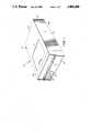
- FIG. 1is a perspective view of a preferred embodiment of an electronic image printing apparatus made in accordance with the principles of the present invention
- FIG. 2is a view similar to FIG. 1 with components broken away to depict in diagrammatic form certain components of the preferred embodiment
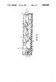
- FIG. 3is a side elevational view in cross-section showing components of the preferred embodiment
- FIG. 4is a longitudinal view taken in cross-section showing other components of the preferred embodiment
- FIG. 5is a perspective view of a film unit usable with the electronic image printing apparatus of the present invention.
- FIG. 5Ais a perspective view of a film cassette usable for holding the film units of the type shown in FIG. 5;
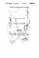
- FIG. 6is a diagrammatic planar view of components forming the electronic image printing apparatus of this invention.
- FIG. 7is a fragmented side elevational view showing components forming part of the film processing mechanism of this embodiment.
- FIG. 8is an enlarged and fragmented view showing a film picking arrangement of the present invention.
- FIG. 9is an enlarged diagrammatic view showing the light emitting elements.
- FIG. 10is a block diagram of control circuitry for use in the apparatus of the present invention.
- FIGS. 1-10for showing a preferred embodiment of an electronic image printing apparatus of the present invention which is designated generally by reference numeral 20.
- the electronic image printing apparatus 20is intended for use in generating and developing images on individual ones of a plurality of photosensitive film units 22 (FIG. 5). These units are of the self-developing type, such as the kind manufactured by Polaroid Corporation. Other kinds of image recording materials are contemplated for use. Whatever kinds are selected though, they would of course be sensitive to exposure by a suitable source of energy used for recording purposes.
- each of the film units 22(FIG. 5) includes an image forming area 22a bordered by a frame 22b having a rupturable pod 22c of processing fluid disposed along a leading marginal edge thereof.
- Each of the film units 22is adapted to be processed following exposure by the electronic image printing apparatus 20 in a manner to be described.
- the pod 22cis ruptured when it is advanced to and between a pair of pressure applying spread rollers, to be described, which cause the processing fluid in the film unit to be spread between positive and image receiving elements (not shown) of such units. This action serves to initiate the diffusion transfer process, whereby latent images on the image forming area 22a are developed.
- the film units 22are held in a stacked array in a film cassette or box 24.
- the film cassette 24(FIG. 5A), it has a generally parallelpiped structure and is made of a suitable opaque plastic material.
- the parallelpiped structureincludes a top wall 26 which defines a generally rectangular light exposure aperture 28 which is arranged to be in registry with the image forming area 22a of successive ones of the film units 22.
- the film cassette 24includes a bottom wall 30 (FIG. 2) leading end wall assembly 32, rearward wall 34 and opposing side walls 36.
- a spring platen or pack spring(not shown) is arranged to provide a yieldable platform for the film units 22 so as to feed successive units to a focal plane defined by the aperture 28. It should be noted that in this embodiment, the film cassette 24 is arranged so that the aperture 28 faces downwardly.
- the image area 22a of each of the successive film units 22 to be exposedis facing downwardly with respect to the topside of the electronic image printing apparatus 20.
- the one of the present embodimentincludes a generally planar battery 38 and a dark slide (not shown).
- the battery 38can provide electrical power for certain operations of the apparatus 20 such as powering the control circuit in the event of an electrical power outage.
- the top wall 26 of the film cassette 24is formed with an elongated recess or cutout 40 which is constructed to allow a picking mechanism, to be described later, to push successive exposed film units 22 through an exit opening 41 formed in the leading end wall assembly 32.
- the housing assembly 42includes a parallelpiped structure having top wall 42a, bottom wall 42b, opposing sidewalls 42c and respective front and back walls 42d and 42e.
- Formed in the top wall 42ais an opening which cooperates with a door 44 mounted for slidable movement between open and closed positions. Whenever the door 44 is open, it allows entry and removal of the film cassette 24.
- the film units 22are intended to be ejected from the film cassette 24 and are advanced through the front wall 42d.
- the front wall 42dincludes an exit or discharge slot 48 which is sized and shaped to allow ejection of a dark slide and a processed film unit 22 therethrough.
- the front wall 42dcan include several appropriate switches and indicators.
- the front wall 42dhas mounted thereon an on-off switch 50 which when actuated effects commencement of an image generating and recording cycle.
- an indicator lamp 52is mounted on the front wall 42d for purposes of indicating that the apparatus 20 is operating.
- a pair of clamping arms 58For releasably clamping the film cassette 24 in the film cassette carriage 46 there is provided a pair of clamping arms 58.
- Each of the clamping arms 58is pivotally mounted on top of a respective one of the linear bearing assemblies 56.
- the clamping arms 58can be pivoted to engage the bottom wall 30 in a manner which causes the film cassette 24 to be securely mounted.
- undesired movement of the film cassette 24 caused by vibrations and the likedo not occur.
- the film cassette carriage 46has a ledge portion 60 defining an aperture 62 which is sized and shaped so that the aperture 28 and, therefore, the entire image area 22a of successive ones of the film units 22 can be exposed.
- the film cassette carriage 46is also formed with a pick slot only partially shown at 63 (FIG. 7) which allows picking of an exposed film unit 22 from the film cassette 24.
- the present inventionincludes compact and integral scanning driving mechanism or means 64 which is operable for simultaneously operating both fast and slow scanning movements.
- FIGS. 2-4 and 6for showing the scanning driving mechanism 64.
- an electric driving motor 66for effecting the slow scan movement there is provided an electric driving motor 66, a gear reduction arrangement 68 and a carriage advance lead screw 70 having threadedly coupled thereto a coupling nut 72 (FIG. 3).
- the coupling nut 72is connected to the film cassette carriage 46.
- the driving motor 66starts and stops responsive to appropriate signals from the apparatus control circuit 74 (FIG. 10).
- the driving motor 66is appropriately energized at the commencement of an image generating and recording cycle and is effective to bidirectionally drive the lead screw 70 through the gear reduction arrangement 68.
- the lead screw 70is supported rotatably in the housing assembly 42 so as to be aligned with the guide rods 54. Rotation of the lead screw 70 advances the cassette carriage 46 roughly less than one micron per revolution of the lead screw. Towards this end the lead screw 70 is a high precision type having, for example a pitch of 80.
- the coupling nut 72is connected to the bottom of a linear bearing assembly 56 by a flexible strap 75. The coupling nut 72 is thus prevented from rotation and thus, rotational movement of the motor's output shaft is converted to axial movement of the cassette carriage 46. This is the so-called slow scan movement of the film cassette carriage 46 which is generally transverse to the fast scan movement. The slow scan speed can, of course, be varied by varying the output speed of the driving motor 66.
- the flexible strap device 75mechanically connects the coupling nut 72 to the linear bearing assembly 56.
- the strap device 75is sufficiently rigid for transferring axial movement in either direction and for resisting screw torque friction.
- the flexible strap device 75prevents alignment and runout errors being transmitted to the carriage 46.
- the flexible strap device 75accepts misalignment in any direction between the lead screw 70 and the guide rod 56.
- a switch contact member 76(FIG. 3) depends from the coupling nut 72 and is adapted to engage limit switches 78 and 80. Each limit switch is located respectively adjacent an opposite end of the coupling nut's movement, such as shown in FIG. 3. Selective actuation of the limit switches 78 and 80 results in ending of linear movement of the film cassette carriage 46 by effectively stopping operation of the driving motor 66.
- fast scanning movementis considered movement of modulated light spots across the width of the film units 22. Both the slow and fast scanning movements provide for raster scan imaging on the image forming area 22a.
- the scanning mirror 90is intended to be rotated preferably by about 20 degrees and includes overtravel. This is sufficient to insure that an exposure or scanning line extends a distance greater than the entire width of each of the imaging areas 22a exposed. This accommodates for slight misalignment of components.
- the scan and rescan timewill be the same. However, the present invention acknowledges that the scan and rescan time can be altered. If it is desired to allow for a shorter rescan time then, for example, the mass of the scanning mirror 90 can be reduced.
- an encoder mechanism 100For regulating firing frequency of the light source there is provided an encoder mechanism 100. Included in the encoder mechanism 100 is an encoder wheel 102 fixedly mounted to the output shaft 88 and which has a plurality of generally radially extending markings (not shown) which are sensed by a conventional optical sensor 104 of the type used in conjunction with encoder wheels.
- the optical sensor 104transmits and receives light through transmissive portions of the encoder wheel 102.
- the optical sensor 104which generates encoder ticks reflects the variations in the rotational speed of the output shaft 88. In this embodiment, each time a signal is sensed by the optical sensor 104, the light source, as will be explained, is energized to emit light.
- each encoder tick of the sensor 104is transmitted to a data clock (not shown) in the control circuit 74. Thereafter, the encoder tick responsive clock pulses are transmitted to a microcomputer (not shown) in the control circuit. Image data received by the microcomputer, from any well-known source, such as magnetic tape or disc is thereafter directed to circuitry (not shown) which modulates the intensity of the output of light emitting diodes 106a-c (FIG. 9). Of course, the electronic image data may be enhanced. Thus, energization of the light emitting diodes 106a-c is a function of the speed of motor output shaft 88 since the encoder ticks are dependent upon the rotational displacement of the encoder wheel 102.
- the three light emitting diodes 106a-care capable of generating color images. While the present embodiment discloses the use of light emitting diodes 106a-c, the present invention contemplates other kinds of energy emitting sources, such as laser diodes. For instance, for laser diodes to be effectively utilized, the image recording material must be sensitive to exposure of the laser's spectral wavelengths.
- the light emitting diodes 106a-care arranged in spaced apart and generally horizontal relationship relative to the base of the housing assembly 42.
- the light emitting diodes 106a-cwhen energized respectively produce red, green and blue spectral wavelengths. It should be noted that the light emitting diodes 106a-c can have other spatial arrangements so long as the light produced by each light emitting diode reaches essentially the same spots on the image forming area 22a.
- the light emitting diodes 106a-cprovide spots or pixel sizes adequate for exposing the film to provide for desired image resolution. In this embodiment, the size of each pixel produced by the light emitting diodes 106a,b is 0.0062 ⁇ 0.003 inches.
- the sequencingis performed in a manner whereby the modulated beam of red light falls on a first spot of the film followed in time, by modulated beams of green and blue light.
- the same film area or spotwill, therefore, be imaged consecutively by the three noted colors. More particularly, while the first spot is being imaged with green light, the next successive spot along the scanning line of exposure in the fast scan direction is being imaged with red light. After the first spot has been consecutively imaged with red and green light, the beam of blue light will be imaged on the first film spot. As the blue light is being imaged on the first film spot, the red light is being imaged on a third film spot, and the second film spot, which has been previously imaged with red light, is being imaged with green light.
- the same film spotwill be imaged consecutively by the three light emitting diodes 106a-c.
- This sequencing of colors on successive spots along the linear pathis continued throughout the fast scan.
- the light emitting diodes 106 a-cby being arranged in a horizontal manner provide a scanning action which is efficient. For example, if the scanning mirror were to scan simultaneously a plurality of lines with red, green and blue light, it will be appreciated that greater precision and control of the mirror scan would be required. This is because the scanning mirror would have to allow each of the colors to scan the same line three different times in order to image the noted three color components. Furthermore, in such a situation more electronic information would be required to be stored. Accordingly, a more complicated and precise mechanism would be otherwise required than is currently proposed.
- the optical system 116provides means for imaging the light bundles or beams from the light emitting diodes 106a-c onto the image forming area 22a through an elongated scanning slot 118 (FIG. 4) formed in a horizontally supported masking plate 120.
- the masking plate 120is supported in the housing assembly 42 immediately adjacent the image areas 22a of the film units 22 to be exposed.
- the scanning slot 118allows formation of the exposure or scanning line.
- the scanning slot 118is arranged to extend across the width of the image areas being exposed.
- the masking plate 120also serves to block stray light from striking undesired parts of the film.
- a resilient low-friction film flattener 121(FIG. 4) is provided so as to interfere slightly with the film unit and is aligned adjacent the exposure line. The reason for this is that the flattener 121 compensates for the fact that the film units 22 are inherently flexible and not entirely flat.
- the film flattener 121provides flat film at the focal plane. The drag provided by the low-friction film flattener 121 is negligible and does not impede the slow scan movement or scratch the film surface.
- FIGS. 7 and 8for showing a processing mechanism 136 for processing each of the exposed film units 22 subsequent to an image printing cycle.
- the processing mechanism 136is similar to that described in U.S. Pat. No. 4,047,192, commonly assigned herewith. Hence, a detailed description is not believed necessary.
- the processing mechanism 136provides a means for processing each of the film units 22 so as to initiate formation of a visible image therein and for advancing each film unit from the slot 41 through the exit slot 48.
- the processing mechanism 136includes a motor 140, a gear train assembly 142 for driving a pair of film processing rollers 144 and 146 and a film picking mechanism 150.
- the film pick drive gear 156drives a sequencing gear 162 through a rotatably supported compound gear 164.
- the film picking mechanism 150is supported for generally reciprocal movement adjacent the film cassette 24.
- the film picking mechanism 150is actuated upon rotation of the motor output shaft 140a.
- Rotation of the output shaft 140arotates the driving gear 152 which results in rotation of the gear 154 and its portion 154a.
- the sequencing gear 162rotates in the direction of the arrows in FIG. 7.
- the sequencing gear 162will make a complete revolution during the film processing cycle.
- the sequencing gear 162includes a lug 166 which is arranged to engage a tab 170 at the forward end of a pick slide 172.
- This engagementcauses sliding movement of the pick slide 172 towards the forward position of the housing assembly 42.
- the pick slide 172is suitably mounted in a support wall 173 mounted in the housing assembly 42.
- the pick slide 172moves against the urging of a spring 174 which has its other end attached to the housing assembly 42.
- the spring 174returns the pick slide 172 to its normal at rest position when the lug 166 no longer engages the tab 170.
- the pick slide 172is advanced for a limited stroke which is effective to cause a pick arm 176 which is connected to the slide 172, to engage the film unit 22.
- the pick arm 176travels through the slot 63 in the film cassette carriage 46 and cutout 40 in the film cassette 24.
- a userplaces a film cassette 24 in the apparatus 20 after moving the sliding door 44 to the open position and placing the cassette face down in the film cassette carriage 46.
- the clamping arms 58are pivoted to overlap and engage the bottom wall 30.
- the cassette 24is in a stable orientation during an operating cycle.
- the apparatus 20is ready, after a suitable time delay, to generate and expose or print images on image forming areas 22a of successive film units.
- Raster scanning of the image to be printedis achieved as follows.
- the control circuits 74includes circuitry effective to again operate the motor 66. As noted, operation of the motor 66 drives synchronously the fast and slow scanning movements. Hence, a single driving means is responsible for driving both fast and slow scanning movements.
Landscapes
- Engineering & Computer Science (AREA)
- Multimedia (AREA)
- Signal Processing (AREA)
- Printers Or Recording Devices Using Electromagnetic And Radiation Means (AREA)
- Facsimile Scanning Arrangements (AREA)
- Fax Reproducing Arrangements (AREA)
- Dot-Matrix Printers And Others (AREA)
- Laser Beam Printer (AREA)
- Projection-Type Copiers In General (AREA)
Abstract
Description
Claims (17)
Priority Applications (5)
| Application Number | Priority Date | Filing Date | Title |
|---|---|---|---|
| US07/158,585US4800400A (en) | 1987-10-05 | 1988-02-22 | Electronic image printing apparatus |
| DE3850028TDE3850028T2 (en) | 1987-10-05 | 1988-09-30 | Electrical image printing device. |
| EP88116187AEP0310961B1 (en) | 1987-10-05 | 1988-09-30 | Electronic image printing apparatus |
| CA000579181ACA1298126C (en) | 1987-10-05 | 1988-10-03 | Electronic image printing apparatus |
| JP63250745AJP2813353B2 (en) | 1987-10-05 | 1988-10-04 | Electronic image printing device |
Applications Claiming Priority (2)
| Application Number | Priority Date | Filing Date | Title |
|---|---|---|---|
| US10477087A | 1987-10-05 | 1987-10-05 | |
| US07/158,585US4800400A (en) | 1987-10-05 | 1988-02-22 | Electronic image printing apparatus |
Related Parent Applications (1)
| Application Number | Title | Priority Date | Filing Date |
|---|---|---|---|
| US10477087AContinuation | 1987-10-05 | 1987-10-05 |
Publications (1)
| Publication Number | Publication Date |
|---|---|
| US4800400Atrue US4800400A (en) | 1989-01-24 |
Family
ID=26801912
Family Applications (1)
| Application Number | Title | Priority Date | Filing Date |
|---|---|---|---|
| US07/158,585Expired - LifetimeUS4800400A (en) | 1987-10-05 | 1988-02-22 | Electronic image printing apparatus |
Country Status (5)
| Country | Link |
|---|---|
| US (1) | US4800400A (en) |
| EP (1) | EP0310961B1 (en) |
| JP (1) | JP2813353B2 (en) |
| CA (1) | CA1298126C (en) |
| DE (1) | DE3850028T2 (en) |
Cited By (22)
| Publication number | Priority date | Publication date | Assignee | Title |
|---|---|---|---|---|
| US4868586A (en)* | 1988-04-29 | 1989-09-19 | Polaroid Corporation | Reversible driving mechanism for electronic printer |
| US4941000A (en)* | 1989-10-13 | 1990-07-10 | Polaroid Corporation | Downloading film access door assembly for electronic imaging apparatus |
| US4985714A (en)* | 1990-01-22 | 1991-01-15 | Polaroid Corporation | Film dispenser with articulated catcher |
| USD317785S (en) | 1988-05-06 | 1991-06-25 | Polaroid Corporation | Electronic film printer |
| USD318871S (en) | 1987-10-30 | 1991-08-06 | Seikosha Co., Ltd. | Video printer |
| USD322275S (en) | 1989-04-25 | 1991-12-10 | Seikosha Co., Ltd. | Video printer |
| USD323346S (en) | 1990-04-25 | 1992-01-21 | Mitsubishi Denki Kabushiki Kaisha | Video imaging printer or the like |
| USD323847S (en) | 1990-04-25 | 1992-02-11 | Mitsubishi Denki Kabushiki Kaisha | Video imaging printer or the like |
| USD334022S (en) | 1990-11-06 | 1993-03-16 | Gold Star, Ltd. | Color video printer |
| USD334402S (en) | 1990-12-05 | 1993-03-30 | Ricoh Company, Ltd. | Video printer |
| US5237361A (en)* | 1992-05-28 | 1993-08-17 | Polaroid Corporation | Film dispenser with improved articulated catcher |
| USD355926S (en) | 1993-02-26 | 1995-02-28 | Sony Corporation | Video printer |
| USD358414S (en) | 1993-06-10 | 1995-05-16 | Seikosha Co., Ltd. | Video printer |
| USD374031S (en) | 1994-08-01 | 1996-09-24 | Sony Corporation | Printer |
| US5841553A (en)* | 1995-12-26 | 1998-11-24 | Xros, Inc. | Compact document scanner or printer engine |
| US6064779A (en)* | 1997-07-23 | 2000-05-16 | Xros, Inc. | Handheld document scanner |
| US6137515A (en)* | 1999-10-04 | 2000-10-24 | Hewlett-Packard Company | Full bleed ink-jet photographic quality printing |
| US6229139B1 (en) | 1998-07-23 | 2001-05-08 | Xros, Inc. | Handheld document scanner |
| USD466919S1 (en) | 2000-04-19 | 2002-12-10 | Able Systems Limited | Printer |
| US6608297B2 (en) | 1997-07-23 | 2003-08-19 | Xeros, Inc. | Scanner document speed encoder |
| US6760121B1 (en)* | 1999-04-28 | 2004-07-06 | Fuji Photo Optical Co., Ltd. | Beam scanning printer |
| US20060039734A1 (en)* | 2004-08-18 | 2006-02-23 | Bingham Jeffrey G | Media stack control |
Citations (11)
| Publication number | Priority date | Publication date | Assignee | Title |
|---|---|---|---|---|
| US4047192A (en)* | 1975-03-03 | 1977-09-06 | Polaroid Corporation | Photographic apparatus with sequencing system |
| US4179183A (en)* | 1977-05-07 | 1979-12-18 | Canon Kabushiki Kaisha | Device for scanning a light beam at a constant speed |
| US4467369A (en)* | 1982-02-25 | 1984-08-21 | Polaroid Corporation | Apparatus for exposing photosensitive material to video frame |
| US4547038A (en)* | 1982-05-04 | 1985-10-15 | Tokyo Shibaura Denki Kabushiki Kaisha | Apparatus for scanning a plane with light beams |
| US4564853A (en)* | 1985-02-08 | 1986-01-14 | Polaroid Corporation | Electronic image sensing and printing apparatus |
| US4566015A (en)* | 1984-06-07 | 1986-01-21 | Polaroid Corporation | Image recording apparatus with adjustable mask |
| US4589745A (en)* | 1985-01-25 | 1986-05-20 | Polaroid Corporation | Geometric LED layout for line exposure |
| US4610536A (en)* | 1985-05-06 | 1986-09-09 | Polaroid Corporation | Laser scanning and printing apparatus |
| US4630128A (en)* | 1983-08-10 | 1986-12-16 | Kabushiki Kaisha Toshiba | Color image forming apparatus with interruption control |
| US4641184A (en)* | 1984-12-14 | 1987-02-03 | Polaroid Corporation | Electronic image scanner and copier system with color matrix image enhancement |
| US4673956A (en)* | 1983-02-09 | 1987-06-16 | Canon Kabushiki Kaisha | Reduced vibration in a two part assembly for an image recording apparatus |
Family Cites Families (5)
| Publication number | Priority date | Publication date | Assignee | Title |
|---|---|---|---|---|
| JPS561245U (en)* | 1979-06-14 | 1981-01-08 | ||
| US4584612A (en)* | 1984-02-21 | 1986-04-22 | Dainippon Screen Seizo Kabushiki Kaisha | Picture recording method |
| JPS61163355A (en)* | 1985-01-14 | 1986-07-24 | Yokogawa Electric Corp | Laser printer |
| JPS61193561A (en)* | 1985-02-21 | 1986-08-28 | Canon Inc | recording device |
| JPS6284041U (en)* | 1985-11-15 | 1987-05-28 |
- 1988
- 1988-02-22USUS07/158,585patent/US4800400A/ennot_activeExpired - Lifetime
- 1988-09-30DEDE3850028Tpatent/DE3850028T2/ennot_activeExpired - Fee Related
- 1988-09-30EPEP88116187Apatent/EP0310961B1/ennot_activeExpired - Lifetime
- 1988-10-03CACA000579181Apatent/CA1298126C/ennot_activeExpired - Fee Related
- 1988-10-04JPJP63250745Apatent/JP2813353B2/ennot_activeExpired - Lifetime
Patent Citations (11)
| Publication number | Priority date | Publication date | Assignee | Title |
|---|---|---|---|---|
| US4047192A (en)* | 1975-03-03 | 1977-09-06 | Polaroid Corporation | Photographic apparatus with sequencing system |
| US4179183A (en)* | 1977-05-07 | 1979-12-18 | Canon Kabushiki Kaisha | Device for scanning a light beam at a constant speed |
| US4467369A (en)* | 1982-02-25 | 1984-08-21 | Polaroid Corporation | Apparatus for exposing photosensitive material to video frame |
| US4547038A (en)* | 1982-05-04 | 1985-10-15 | Tokyo Shibaura Denki Kabushiki Kaisha | Apparatus for scanning a plane with light beams |
| US4673956A (en)* | 1983-02-09 | 1987-06-16 | Canon Kabushiki Kaisha | Reduced vibration in a two part assembly for an image recording apparatus |
| US4630128A (en)* | 1983-08-10 | 1986-12-16 | Kabushiki Kaisha Toshiba | Color image forming apparatus with interruption control |
| US4566015A (en)* | 1984-06-07 | 1986-01-21 | Polaroid Corporation | Image recording apparatus with adjustable mask |
| US4641184A (en)* | 1984-12-14 | 1987-02-03 | Polaroid Corporation | Electronic image scanner and copier system with color matrix image enhancement |
| US4589745A (en)* | 1985-01-25 | 1986-05-20 | Polaroid Corporation | Geometric LED layout for line exposure |
| US4564853A (en)* | 1985-02-08 | 1986-01-14 | Polaroid Corporation | Electronic image sensing and printing apparatus |
| US4610536A (en)* | 1985-05-06 | 1986-09-09 | Polaroid Corporation | Laser scanning and printing apparatus |
Cited By (24)
| Publication number | Priority date | Publication date | Assignee | Title |
|---|---|---|---|---|
| USD318871S (en) | 1987-10-30 | 1991-08-06 | Seikosha Co., Ltd. | Video printer |
| US4868586A (en)* | 1988-04-29 | 1989-09-19 | Polaroid Corporation | Reversible driving mechanism for electronic printer |
| USD317785S (en) | 1988-05-06 | 1991-06-25 | Polaroid Corporation | Electronic film printer |
| USD322275S (en) | 1989-04-25 | 1991-12-10 | Seikosha Co., Ltd. | Video printer |
| US4941000A (en)* | 1989-10-13 | 1990-07-10 | Polaroid Corporation | Downloading film access door assembly for electronic imaging apparatus |
| WO1991006033A1 (en)* | 1989-10-13 | 1991-05-02 | Polaroid Corporation | Down loading film access door assembly for electronic imaging apparatus |
| US4985714A (en)* | 1990-01-22 | 1991-01-15 | Polaroid Corporation | Film dispenser with articulated catcher |
| USD323346S (en) | 1990-04-25 | 1992-01-21 | Mitsubishi Denki Kabushiki Kaisha | Video imaging printer or the like |
| USD323847S (en) | 1990-04-25 | 1992-02-11 | Mitsubishi Denki Kabushiki Kaisha | Video imaging printer or the like |
| USD334022S (en) | 1990-11-06 | 1993-03-16 | Gold Star, Ltd. | Color video printer |
| USD334402S (en) | 1990-12-05 | 1993-03-30 | Ricoh Company, Ltd. | Video printer |
| US5237361A (en)* | 1992-05-28 | 1993-08-17 | Polaroid Corporation | Film dispenser with improved articulated catcher |
| USD355926S (en) | 1993-02-26 | 1995-02-28 | Sony Corporation | Video printer |
| USD358414S (en) | 1993-06-10 | 1995-05-16 | Seikosha Co., Ltd. | Video printer |
| USD374031S (en) | 1994-08-01 | 1996-09-24 | Sony Corporation | Printer |
| US5841553A (en)* | 1995-12-26 | 1998-11-24 | Xros, Inc. | Compact document scanner or printer engine |
| US6064779A (en)* | 1997-07-23 | 2000-05-16 | Xros, Inc. | Handheld document scanner |
| US6608297B2 (en) | 1997-07-23 | 2003-08-19 | Xeros, Inc. | Scanner document speed encoder |
| US6229139B1 (en) | 1998-07-23 | 2001-05-08 | Xros, Inc. | Handheld document scanner |
| US6760121B1 (en)* | 1999-04-28 | 2004-07-06 | Fuji Photo Optical Co., Ltd. | Beam scanning printer |
| US6137515A (en)* | 1999-10-04 | 2000-10-24 | Hewlett-Packard Company | Full bleed ink-jet photographic quality printing |
| USD466919S1 (en) | 2000-04-19 | 2002-12-10 | Able Systems Limited | Printer |
| US20060039734A1 (en)* | 2004-08-18 | 2006-02-23 | Bingham Jeffrey G | Media stack control |
| US7568850B2 (en) | 2004-08-18 | 2009-08-04 | Hewlett-Packard Development Company, L.P. | Media stack control |
Also Published As
| Publication number | Publication date |
|---|---|
| EP0310961B1 (en) | 1994-06-08 |
| DE3850028D1 (en) | 1994-07-14 |
| EP0310961A3 (en) | 1991-04-24 |
| EP0310961A2 (en) | 1989-04-12 |
| JPH01127356A (en) | 1989-05-19 |
| DE3850028T2 (en) | 1994-10-06 |
| CA1298126C (en) | 1992-03-31 |
| JP2813353B2 (en) | 1998-10-22 |
Similar Documents
| Publication | Publication Date | Title |
|---|---|---|
| US4800400A (en) | Electronic image printing apparatus | |
| US5754314A (en) | Image input system and method for reading images from an original document | |
| US5461492A (en) | Film scanner with in-line dual scanning gates | |
| US4750049A (en) | Hand-held copying apparatus | |
| JPH07264470A (en) | Method and equipment for film locating | |
| US4809020A (en) | Control apparatus for electronic image printer | |
| US4952946A (en) | Scanning beam position detecting apparatus for use in electronic printer | |
| US4804982A (en) | Printer having reversible driving mechanism | |
| US6573925B2 (en) | Optical printer module | |
| JP2716358B2 (en) | Method and camera for recording data on photographic film | |
| EP0282044B1 (en) | Scanning exposure device | |
| CA1299744C (en) | Aperture card printer | |
| US4912488A (en) | Camera with image input from linear array of electric-to-light transducers | |
| JPS59209197A (en) | Method and device for copying colored picture | |
| US5160958A (en) | Image projecting apparatus | |
| EP0751667A2 (en) | Strip recording media exposure using a rotating drum recorder | |
| US5661545A (en) | Strip recording media exposure using a rotating drum recorder | |
| USRE38541E1 (en) | Camera equipped with data imprinting device | |
| US4286853A (en) | Microfiche camera having motor control system | |
| KR100444271B1 (en) | Color image forming method and apparatus | |
| JPH0832760A (en) | Film image input system | |
| JPH0865469A (en) | Film image input device | |
| JPH01206365A (en) | information recording device | |
| JPH0837618A (en) | Document holder | |
| JPS58987B2 (en) | Imaging device in phototypesetting machine |
Legal Events
| Date | Code | Title | Description |
|---|---|---|---|
| STCF | Information on status: patent grant | Free format text:PATENTED CASE | |
| FEPP | Fee payment procedure | Free format text:PAYOR NUMBER ASSIGNED (ORIGINAL EVENT CODE: ASPN); ENTITY STATUS OF PATENT OWNER: LARGE ENTITY | |
| FPAY | Fee payment | Year of fee payment:4 | |
| FPAY | Fee payment | Year of fee payment:8 | |
| FPAY | Fee payment | Year of fee payment:12 | |
| AS | Assignment | Owner name:MORGAN GUARANTY TRUST COMPANY OF NEW YORK, NEW YOR Free format text:SECURITY AGREEMENT;ASSIGNOR:POLAROID CORPORATION;REEL/FRAME:011658/0699 Effective date:20010321 | |
| AS | Assignment | Owner name:OEP IMAGINIG OPERATING CORPORATION, NEW YORK Free format text:ASSIGNMENT OF ASSIGNORS INTEREST;ASSIGNOR:POLAROID CORPORATION;REEL/FRAME:016427/0144 Effective date:20020731 Owner name:POLAROID CORPORATION, NEW YORK Free format text:CHANGE OF NAME;ASSIGNOR:OEP IMAGING OPERATING CORPORATION;REEL/FRAME:016470/0006 Effective date:20020801 Owner name:OEP IMAGINIG OPERATING CORPORATION,NEW YORK Free format text:ASSIGNMENT OF ASSIGNORS INTEREST;ASSIGNOR:POLAROID CORPORATION;REEL/FRAME:016427/0144 Effective date:20020731 Owner name:POLAROID CORPORATION,NEW YORK Free format text:CHANGE OF NAME;ASSIGNOR:OEP IMAGING OPERATING CORPORATION;REEL/FRAME:016470/0006 Effective date:20020801 | |
| AS | Assignment | Owner name:WILMINGTON TRUST COMPANY, AS COLLATERAL AGENT, DEL Free format text:ASSIGNMENT OF ASSIGNORS INTEREST;ASSIGNORS:POLAROLD HOLDING COMPANY;POLAROID CORPORATION;POLAROID ASIA PACIFIC LLC;AND OTHERS;REEL/FRAME:016602/0332 Effective date:20050428 Owner name:JPMORGAN CHASE BANK,N.A,AS ADMINISTRATIVE AGENT, W Free format text:SECURITY INTEREST;ASSIGNORS:POLAROID HOLDING COMPANY;POLAROID CORPORATION;POLAROID ASIA PACIFIC LLC;AND OTHERS;REEL/FRAME:016602/0603 Effective date:20050428 Owner name:WILMINGTON TRUST COMPANY, AS COLLATERAL AGENT,DELA Free format text:SECURITY AGREEMENT;ASSIGNORS:POLAROLD HOLDING COMPANY;POLAROID CORPORATION;POLAROID ASIA PACIFIC LLC;AND OTHERS;REEL/FRAME:016602/0332 Effective date:20050428 Owner name:JPMORGAN CHASE BANK,N.A,AS ADMINISTRATIVE AGENT,WI Free format text:SECURITY INTEREST;ASSIGNORS:POLAROID HOLDING COMPANY;POLAROID CORPORATION;POLAROID ASIA PACIFIC LLC;AND OTHERS;REEL/FRAME:016602/0603 Effective date:20050428 Owner name:WILMINGTON TRUST COMPANY, AS COLLATERAL AGENT, DEL Free format text:SECURITY AGREEMENT;ASSIGNORS:POLAROLD HOLDING COMPANY;POLAROID CORPORATION;POLAROID ASIA PACIFIC LLC;AND OTHERS;REEL/FRAME:016602/0332 Effective date:20050428 | |
| AS | Assignment | Owner name:POLAROID CORPORATION (F/K/A OEP IMAGING OPERATING Free format text:U.S. BANKRUPTCY COURT DISTRICT OF DELAWARE ORDER AUTHORIZING RELEASE OF ALL LIENS;ASSIGNOR:JPMORGAN CHASE BANK, N.A. (F/K/A MORGAN GUARANTY TRUST COMPANY OF NEW YORK);REEL/FRAME:016621/0377 Effective date:20020418 | |
| AS | Assignment | Owner name:OEP IMAGING OPERATING CORPORATION,NEW YORK Free format text:ASSIGNMENT OF ASSIGNORS INTEREST;ASSIGNOR:POLAROID CORPORATION;REEL/FRAME:018584/0600 Effective date:20020731 Owner name:OEP IMAGING OPERATING CORPORATION, NEW YORK Free format text:ASSIGNMENT OF ASSIGNORS INTEREST;ASSIGNOR:POLAROID CORPORATION;REEL/FRAME:018584/0600 Effective date:20020731 | |
| AS | Assignment | Owner name:POLAROID CORPORATION (FMR OEP IMAGING OPERATING CO Free format text:SUPPLEMENTAL ASSIGNMENT OF PATENTS;ASSIGNOR:PRIMARY PDC, INC. (FMR POLAROID CORPORATION);REEL/FRAME:019077/0001 Effective date:20070122 | |
| AS | Assignment | Owner name:POLAROID HOLDING COMPANY, MASSACHUSETTS Free format text:RELEASE OF SECURITY INTEREST IN PATENTS;ASSIGNOR:WILMINGTON TRUST COMPANY;REEL/FRAME:019699/0512 Effective date:20070425 Owner name:POLAROID CORPORATION, MASSACHUSETTS Free format text:RELEASE OF SECURITY INTEREST IN PATENTS;ASSIGNOR:WILMINGTON TRUST COMPANY;REEL/FRAME:019699/0512 Effective date:20070425 Owner name:POLAROID CAPITAL LLC, MASSACHUSETTS Free format text:RELEASE OF SECURITY INTEREST IN PATENTS;ASSIGNOR:WILMINGTON TRUST COMPANY;REEL/FRAME:019699/0512 Effective date:20070425 Owner name:POLAROID ASIA PACIFIC LLC, MASSACHUSETTS Free format text:RELEASE OF SECURITY INTEREST IN PATENTS;ASSIGNOR:WILMINGTON TRUST COMPANY;REEL/FRAME:019699/0512 Effective date:20070425 Owner name:POLAROID EYEWEAR LLC, MASSACHUSETTS Free format text:RELEASE OF SECURITY INTEREST IN PATENTS;ASSIGNOR:WILMINGTON TRUST COMPANY;REEL/FRAME:019699/0512 Effective date:20070425 Owner name:POLOROID INTERNATIONAL HOLDING LLC, MASSACHUSETTS Free format text:RELEASE OF SECURITY INTEREST IN PATENTS;ASSIGNOR:WILMINGTON TRUST COMPANY;REEL/FRAME:019699/0512 Effective date:20070425 Owner name:POLAROID INVESTMENT LLC, MASSACHUSETTS Free format text:RELEASE OF SECURITY INTEREST IN PATENTS;ASSIGNOR:WILMINGTON TRUST COMPANY;REEL/FRAME:019699/0512 Effective date:20070425 Owner name:POLAROID LATIN AMERICA I CORPORATION, MASSACHUSETT Free format text:RELEASE OF SECURITY INTEREST IN PATENTS;ASSIGNOR:WILMINGTON TRUST COMPANY;REEL/FRAME:019699/0512 Effective date:20070425 Owner name:POLAROID NEW BEDFORD REAL ESTATE LLC, MASSACHUSETT Free format text:RELEASE OF SECURITY INTEREST IN PATENTS;ASSIGNOR:WILMINGTON TRUST COMPANY;REEL/FRAME:019699/0512 Effective date:20070425 Owner name:POLAROID NORWOOD REAL ESTATE LLC, MASSACHUSETTS Free format text:RELEASE OF SECURITY INTEREST IN PATENTS;ASSIGNOR:WILMINGTON TRUST COMPANY;REEL/FRAME:019699/0512 Effective date:20070425 Owner name:POLAROID WALTHAM REAL ESTATE LLC, MASSACHUSETTS Free format text:RELEASE OF SECURITY INTEREST IN PATENTS;ASSIGNOR:WILMINGTON TRUST COMPANY;REEL/FRAME:019699/0512 Effective date:20070425 Owner name:PETTERS CONSUMER BRANDS, LLC, MASSACHUSETTS Free format text:RELEASE OF SECURITY INTEREST IN PATENTS;ASSIGNOR:WILMINGTON TRUST COMPANY;REEL/FRAME:019699/0512 Effective date:20070425 Owner name:PETTERS CONSUMER BRANDS INTERNATIONAL, LLC, MASSAC Free format text:RELEASE OF SECURITY INTEREST IN PATENTS;ASSIGNOR:WILMINGTON TRUST COMPANY;REEL/FRAME:019699/0512 Effective date:20070425 Owner name:ZINK INCORPORATED, MASSACHUSETTS Free format text:RELEASE OF SECURITY INTEREST IN PATENTS;ASSIGNOR:WILMINGTON TRUST COMPANY;REEL/FRAME:019699/0512 Effective date:20070425 Owner name:POLAROID HOLDING COMPANY,MASSACHUSETTS Free format text:RELEASE OF SECURITY INTEREST IN PATENTS;ASSIGNOR:WILMINGTON TRUST COMPANY;REEL/FRAME:019699/0512 Effective date:20070425 Owner name:POLAROID CORPORATION,MASSACHUSETTS Free format text:RELEASE OF SECURITY INTEREST IN PATENTS;ASSIGNOR:WILMINGTON TRUST COMPANY;REEL/FRAME:019699/0512 Effective date:20070425 Owner name:POLAROID CAPITAL LLC,MASSACHUSETTS Free format text:RELEASE OF SECURITY INTEREST IN PATENTS;ASSIGNOR:WILMINGTON TRUST COMPANY;REEL/FRAME:019699/0512 Effective date:20070425 Owner name:POLAROID ASIA PACIFIC LLC,MASSACHUSETTS Free format text:RELEASE OF SECURITY INTEREST IN PATENTS;ASSIGNOR:WILMINGTON TRUST COMPANY;REEL/FRAME:019699/0512 Effective date:20070425 Owner name:POLAROID EYEWEAR LLC,MASSACHUSETTS Free format text:RELEASE OF SECURITY INTEREST IN PATENTS;ASSIGNOR:WILMINGTON TRUST COMPANY;REEL/FRAME:019699/0512 Effective date:20070425 Owner name:POLOROID INTERNATIONAL HOLDING LLC,MASSACHUSETTS Free format text:RELEASE OF SECURITY INTEREST IN PATENTS;ASSIGNOR:WILMINGTON TRUST COMPANY;REEL/FRAME:019699/0512 Effective date:20070425 Owner name:POLAROID INVESTMENT LLC,MASSACHUSETTS Free format text:RELEASE OF SECURITY INTEREST IN PATENTS;ASSIGNOR:WILMINGTON TRUST COMPANY;REEL/FRAME:019699/0512 Effective date:20070425 Owner name:POLAROID LATIN AMERICA I CORPORATION,MASSACHUSETTS Free format text:RELEASE OF SECURITY INTEREST IN PATENTS;ASSIGNOR:WILMINGTON TRUST COMPANY;REEL/FRAME:019699/0512 Effective date:20070425 Owner name:POLAROID NEW BEDFORD REAL ESTATE LLC,MASSACHUSETTS Free format text:RELEASE OF SECURITY INTEREST IN PATENTS;ASSIGNOR:WILMINGTON TRUST COMPANY;REEL/FRAME:019699/0512 Effective date:20070425 Owner name:POLAROID NORWOOD REAL ESTATE LLC,MASSACHUSETTS Free format text:RELEASE OF SECURITY INTEREST IN PATENTS;ASSIGNOR:WILMINGTON TRUST COMPANY;REEL/FRAME:019699/0512 Effective date:20070425 Owner name:POLAROID WALTHAM REAL ESTATE LLC,MASSACHUSETTS Free format text:RELEASE OF SECURITY INTEREST IN PATENTS;ASSIGNOR:WILMINGTON TRUST COMPANY;REEL/FRAME:019699/0512 Effective date:20070425 Owner name:PETTERS CONSUMER BRANDS, LLC,MASSACHUSETTS Free format text:RELEASE OF SECURITY INTEREST IN PATENTS;ASSIGNOR:WILMINGTON TRUST COMPANY;REEL/FRAME:019699/0512 Effective date:20070425 Owner name:PETTERS CONSUMER BRANDS INTERNATIONAL, LLC,MASSACH Free format text:RELEASE OF SECURITY INTEREST IN PATENTS;ASSIGNOR:WILMINGTON TRUST COMPANY;REEL/FRAME:019699/0512 Effective date:20070425 Owner name:ZINK INCORPORATED,MASSACHUSETTS Free format text:RELEASE OF SECURITY INTEREST IN PATENTS;ASSIGNOR:WILMINGTON TRUST COMPANY;REEL/FRAME:019699/0512 Effective date:20070425 | |
| AS | Assignment | Owner name:POLAROID HOLDING COMPANY, MASSACHUSETTS Free format text:RELEASE OF SECURITY INTEREST IN PATENTS;ASSIGNOR:JPMORGAN CHASE BANK, N.A.;REEL/FRAME:020733/0001 Effective date:20080225 Owner name:POLAROID INTERNATIONAL HOLDING LLC, MASSACHUSETTS Free format text:RELEASE OF SECURITY INTEREST IN PATENTS;ASSIGNOR:JPMORGAN CHASE BANK, N.A.;REEL/FRAME:020733/0001 Effective date:20080225 Owner name:POLAROID INVESTMENT LLC, MASSACHUSETTS Free format text:RELEASE OF SECURITY INTEREST IN PATENTS;ASSIGNOR:JPMORGAN CHASE BANK, N.A.;REEL/FRAME:020733/0001 Effective date:20080225 Owner name:POLAROID LATIN AMERICA I CORPORATION, MASSACHUSETT Free format text:RELEASE OF SECURITY INTEREST IN PATENTS;ASSIGNOR:JPMORGAN CHASE BANK, N.A.;REEL/FRAME:020733/0001 Effective date:20080225 Owner name:POLAROID NEW BEDFORD REAL ESTATE LLC, MASSACHUSETT Free format text:RELEASE OF SECURITY INTEREST IN PATENTS;ASSIGNOR:JPMORGAN CHASE BANK, N.A.;REEL/FRAME:020733/0001 Effective date:20080225 Owner name:POLAROID NORWOOD REAL ESTATE LLC, MASSACHUSETTS Free format text:RELEASE OF SECURITY INTEREST IN PATENTS;ASSIGNOR:JPMORGAN CHASE BANK, N.A.;REEL/FRAME:020733/0001 Effective date:20080225 Owner name:POLAROID WALTHAM REAL ESTATE LLC, MASSACHUSETTS Free format text:RELEASE OF SECURITY INTEREST IN PATENTS;ASSIGNOR:JPMORGAN CHASE BANK, N.A.;REEL/FRAME:020733/0001 Effective date:20080225 Owner name:POLAROID CONSUMER ELECTRONICS, LLC, (FORMERLY KNOW Free format text:RELEASE OF SECURITY INTEREST IN PATENTS;ASSIGNOR:JPMORGAN CHASE BANK, N.A.;REEL/FRAME:020733/0001 Effective date:20080225 Owner name:POLAROID CONSUMER ELECTRONICS INTERNATIONAL, LLC, Free format text:RELEASE OF SECURITY INTEREST IN PATENTS;ASSIGNOR:JPMORGAN CHASE BANK, N.A.;REEL/FRAME:020733/0001 Effective date:20080225 Owner name:ZINK INCORPORATED, MASSACHUSETTS Free format text:RELEASE OF SECURITY INTEREST IN PATENTS;ASSIGNOR:JPMORGAN CHASE BANK, N.A.;REEL/FRAME:020733/0001 Effective date:20080225 Owner name:POLAROID CORPORATION, MASSACHUSETTS Free format text:RELEASE OF SECURITY INTEREST IN PATENTS;ASSIGNOR:JPMORGAN CHASE BANK, N.A.;REEL/FRAME:020733/0001 Effective date:20080225 Owner name:POLAROID ASIA PACIFIC LLC, MASSACHUSETTS Free format text:RELEASE OF SECURITY INTEREST IN PATENTS;ASSIGNOR:JPMORGAN CHASE BANK, N.A.;REEL/FRAME:020733/0001 Effective date:20080225 Owner name:POLAROID CAPITAL LLC, MASSACHUSETTS Free format text:RELEASE OF SECURITY INTEREST IN PATENTS;ASSIGNOR:JPMORGAN CHASE BANK, N.A.;REEL/FRAME:020733/0001 Effective date:20080225 Owner name:PLLAROID EYEWEAR I LLC, MASSACHUSETTS Free format text:RELEASE OF SECURITY INTEREST IN PATENTS;ASSIGNOR:JPMORGAN CHASE BANK, N.A.;REEL/FRAME:020733/0001 Effective date:20080225 Owner name:POLAROID HOLDING COMPANY,MASSACHUSETTS Free format text:RELEASE OF SECURITY INTEREST IN PATENTS;ASSIGNOR:JPMORGAN CHASE BANK, N.A.;REEL/FRAME:020733/0001 Effective date:20080225 Owner name:POLAROID INTERNATIONAL HOLDING LLC,MASSACHUSETTS Free format text:RELEASE OF SECURITY INTEREST IN PATENTS;ASSIGNOR:JPMORGAN CHASE BANK, N.A.;REEL/FRAME:020733/0001 Effective date:20080225 Owner name:POLAROID INVESTMENT LLC,MASSACHUSETTS Free format text:RELEASE OF SECURITY INTEREST IN PATENTS;ASSIGNOR:JPMORGAN CHASE BANK, N.A.;REEL/FRAME:020733/0001 Effective date:20080225 Owner name:POLAROID LATIN AMERICA I CORPORATION,MASSACHUSETTS Free format text:RELEASE OF SECURITY INTEREST IN PATENTS;ASSIGNOR:JPMORGAN CHASE BANK, N.A.;REEL/FRAME:020733/0001 Effective date:20080225 Owner name:POLAROID NEW BEDFORD REAL ESTATE LLC,MASSACHUSETTS Free format text:RELEASE OF SECURITY INTEREST IN PATENTS;ASSIGNOR:JPMORGAN CHASE BANK, N.A.;REEL/FRAME:020733/0001 Effective date:20080225 Owner name:POLAROID NORWOOD REAL ESTATE LLC,MASSACHUSETTS Free format text:RELEASE OF SECURITY INTEREST IN PATENTS;ASSIGNOR:JPMORGAN CHASE BANK, N.A.;REEL/FRAME:020733/0001 Effective date:20080225 Owner name:POLAROID WALTHAM REAL ESTATE LLC,MASSACHUSETTS Free format text:RELEASE OF SECURITY INTEREST IN PATENTS;ASSIGNOR:JPMORGAN CHASE BANK, N.A.;REEL/FRAME:020733/0001 Effective date:20080225 Owner name:ZINK INCORPORATED,MASSACHUSETTS Free format text:RELEASE OF SECURITY INTEREST IN PATENTS;ASSIGNOR:JPMORGAN CHASE BANK, N.A.;REEL/FRAME:020733/0001 Effective date:20080225 Owner name:POLAROID CORPORATION,MASSACHUSETTS Free format text:RELEASE OF SECURITY INTEREST IN PATENTS;ASSIGNOR:JPMORGAN CHASE BANK, N.A.;REEL/FRAME:020733/0001 Effective date:20080225 Owner name:POLAROID ASIA PACIFIC LLC,MASSACHUSETTS Free format text:RELEASE OF SECURITY INTEREST IN PATENTS;ASSIGNOR:JPMORGAN CHASE BANK, N.A.;REEL/FRAME:020733/0001 Effective date:20080225 Owner name:POLAROID CAPITAL LLC,MASSACHUSETTS Free format text:RELEASE OF SECURITY INTEREST IN PATENTS;ASSIGNOR:JPMORGAN CHASE BANK, N.A.;REEL/FRAME:020733/0001 Effective date:20080225 Owner name:PLLAROID EYEWEAR I LLC,MASSACHUSETTS Free format text:RELEASE OF SECURITY INTEREST IN PATENTS;ASSIGNOR:JPMORGAN CHASE BANK, N.A.;REEL/FRAME:020733/0001 Effective date:20080225 | |
| AS | Assignment | Owner name:SENSHIN CAPITAL, LLC, DELAWARE Free format text:ASSIGNMENT OF ASSIGNORS INTEREST;ASSIGNOR:POLAROID CORPORATION;REEL/FRAME:021040/0001 Effective date:20080415 Owner name:SENSHIN CAPITAL, LLC,DELAWARE Free format text:ASSIGNMENT OF ASSIGNORS INTEREST;ASSIGNOR:POLAROID CORPORATION;REEL/FRAME:021040/0001 Effective date:20080415 |