US4800392A - Integral laminar antenna and radio housing - Google Patents
Integral laminar antenna and radio housingDownload PDFInfo
- Publication number
- US4800392A US4800392AUS07/001,284US128487AUS4800392AUS 4800392 AUS4800392 AUS 4800392AUS 128487 AUS128487 AUS 128487AUS 4800392 AUS4800392 AUS 4800392A
- Authority
- US
- United States
- Prior art keywords
- lamina
- antenna
- radiator
- ground plane
- dielectric
- Prior art date
- Legal status (The legal status is an assumption and is not a legal conclusion. Google has not performed a legal analysis and makes no representation as to the accuracy of the status listed.)
- Expired - Fee Related
Links
Images


Classifications
- H—ELECTRICITY
- H01—ELECTRIC ELEMENTS
- H01Q—ANTENNAS, i.e. RADIO AERIALS
- H01Q21/00—Antenna arrays or systems
- H01Q21/30—Combinations of separate antenna units operating in different wavebands and connected to a common feeder system
- H—ELECTRICITY
- H01—ELECTRIC ELEMENTS
- H01Q—ANTENNAS, i.e. RADIO AERIALS
- H01Q1/00—Details of, or arrangements associated with, antennas
- H01Q1/12—Supports; Mounting means
- H01Q1/22—Supports; Mounting means by structural association with other equipment or articles
- H01Q1/24—Supports; Mounting means by structural association with other equipment or articles with receiving set
- H01Q1/241—Supports; Mounting means by structural association with other equipment or articles with receiving set used in mobile communications, e.g. GSM
- H01Q1/242—Supports; Mounting means by structural association with other equipment or articles with receiving set used in mobile communications, e.g. GSM specially adapted for hand-held use
- H01Q1/243—Supports; Mounting means by structural association with other equipment or articles with receiving set used in mobile communications, e.g. GSM specially adapted for hand-held use with built-in antennas
- H—ELECTRICITY
- H01—ELECTRIC ELEMENTS
- H01Q—ANTENNAS, i.e. RADIO AERIALS
- H01Q5/00—Arrangements for simultaneous operation of antennas on two or more different wavebands, e.g. dual-band or multi-band arrangements
- H01Q5/40—Imbricated or interleaved structures; Combined or electromagnetically coupled arrangements, e.g. comprising two or more non-connected fed radiating elements
- H—ELECTRICITY
- H01—ELECTRIC ELEMENTS
- H01Q—ANTENNAS, i.e. RADIO AERIALS
- H01Q9/00—Electrically-short antennas having dimensions not more than twice the operating wavelength and consisting of conductive active radiating elements
- H01Q9/04—Resonant antennas
- H01Q9/0407—Substantially flat resonant element parallel to ground plane, e.g. patch antenna
Definitions
- Portable radio transceiverstypically include a one-quarter wavelength end-fed, helical, or one-half wavelength center-fed dipole antenna that protrudes from the radio housing.
- the antennais usually flexible in design to prevent damage, not only to the antenna itself, but also to any person who may come into contact with the antenna.
- a connectortypically attached the antenna to the radio housing so that the antenna can be easily removed from the radio.
- an antennacould be developed which has a very low profile such that it could be mounted in or on the radio housing without protrusion. It would also be desirable to eliminate the impedance matching network and reduce the manufacturing cost of the antenna. It would be advantageous, however, to approximate the radiation pattern of the prior art center-fed dipole antenna.
- the inventionis a laminar antenna that includes a plurality of laminae superposed one another in the following order: conductive ground plane lamina, a first dielectric lamina, a conductive exiter lamina, a second dielectric lamina, and a conductive radiator lamina that partially overlaps the exciter lamina.
- the inventionis an integral radio housing and laminar antenna that includes a radio housing having a wall with first and second surfaces.
- a laminar antennais positioned between the first and second surfaces of the housing wall.
- the laminar antennaincludes a plurality of laminae superposed one another in the following order: a conductive ground plane lamina, a first dielectric lamina, a conductive exciter lamina, a second dielectric lamina, and a conductive radiator lamina partially overlapping the exciter lamina.
- a wideband embodiment of the laminar antennaincludes a plurality of laminae superposed one another in the following order: a conductive ground plane lamina, a first dielectric lamina, a conductive exciter lamina, a second dielectric laminae, and a plurality of coplanar conductive radiator laminae partially overlapping the exciter lamina.
- Each of the radiator laminaeare of a different electrical length whereby a substantially flat bandwidth is provided from the lowest resonant frequency of the longest radiator to the highest resonant frequency of the shortest radiator.
- a duplex embodiment of the laminar antenna for simultaneously transmitting and receivingincludes a plurality of laminae superposed one another in the following order: a conductive ground plane lamina, a first dielectric lamina, a conductive exciter lamina, a second dielectric lamina, and transmit and receive coplanar conductive radiator laminae each of which partially overlaps the exciter lamina.
- the trasmit and receive radiatorsare resonant respectively at transmit and receive frequencies. Substantial isolation is provided between the transmit and receive frequencies.
- FIG. 1is a plan view of a single radiator embodiment of the laminar antenna.
- FIG. 2is a sectional view of the laminar antenna as seen along line 2--2 of FIG. 1.
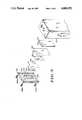
- FIG. 3is an exploded perspective view of an integral radio housing and laminar antenna.
- FIG. 4is a plan view of a widened embodiment of the laminar antenna.
- FIG. 5is a plan view of a duplex embodiment of the laminar antenna.
- FIG. 6is a sectional view of another embodiment of the laminar antenna.
- a conductive ground plane lamina 102preferably a thin sheet of copper, has a hole 104 suitable for receiving a coaxial trasmission line (not illustrated.
- a first dielectric lamina 106(visible only in FIG. 2) is superposed on ground plane 102.
- An exciter lamina 108also preferably a thin copper sheet, is superposed on first dielectric lamina 106.
- Exciter 108has a terminal 110 for connection to the center conductor of a coaxial transmission line while ground plane 102 has a terminal 112 for connection to the shield of the transmission line.
- the transmission lineis preferably soldered to terminals 110 and 112.
- a second dielectric lamina 114is superposed on exciter 108. It should be evident from FIG. 2 that exciter 108 does not extend the full length of the antenna. Thus, below exciter 108, second dielectric lamina 114 is actually superposed on first dielectric lamina 106.
- Dielectric laminae 106 and 114are constructed from Barium Neodymium Titanate, are 80 mm long by 12 mm wide, and are respectively 2 mm and 1 mm thick.
- Radiator lamina 116is superposed of dielectric lamina 114 and 61.7 mm long by 10 mm wide.
- the electrical length of radiator 116should be one-half wavelength, taking into account the dielectric constant of laminae 106 and 114 (the dielectric constant of Barium Neodymium Titanate is 92).
- the use of a high dielectric constant materialshortens the physical length of radiator 116, however, the Q of the antenna will also be higher (i.e., narrower bandwidth).
- the thickness of conductive laminae 102, 108 and 116should be at least three skin depths at the desired operating frequency.
- the overlap 118 of radiator 116 and exciter 108can be adjusted to match impedance of the antenna at terminals 110 and 112) to the impedance of the transmission line.
- the greater the overlapthe lower the antenna impedance.
- overlap 118is approximately 1 mm and the antenna impedance is 50 Ohms.
- FIG. 3illustrates how the previously described single radiator laminar antenna can be constructed into the cover of a radio housing.
- a housing cover 302covers an opening on the rear of radio housing 304 and is secured thereto by screws 306a through 306d (306d is not visible in FIG. 3).
- Cover 302 and housing 304are preferably molded from polycarbonate plastic, although other materials may also be suitable.
- On the inside of cover 302are molded recesses 308, 310, 312 and 314 which are suitable for receiving radiator 116, dielectric laminae 106 and 114, exciter 108, and ground plane 102 respectively.
- a cap 316preferably a thin sheet of polycarbonate, is also positioned in recess 314 and is preferably ultrasonically welded to cover 302. After assembly, the laminar antenna is completely contained between the inner and outer surfaces of rear cover 302. A hole 318 in cap 316 accepts a coaxial transmission line to connect the antenna to the radio circuitry contained in housing 304.
- Other methods for positioning the laminar antenna within the walls of the housingare also possible. For example, the laminar antenna could be molded into one wall of radio housing 304.
- Radio housing 304also contains a push-to-talk (PTT) switch 320.
- PTT switch 320is positioned below the laminar antenna such that when the user's hand activates the switch, the hand does not cover the antenna.
- FIG. 4a plan view of a wideband embodiment of the laminar antenna is illustrated.
- This antennais similar in design to the single radiator embodiment of FIGS. 1 and 2, however, the wideband embodiment has a plurality of radiators 402, 404, 406 and 408.
- First and second dielectric laminae 106' and 114' (106' is not visible in FIG. 4), and exciter 108'are respectively similar to dielectric laminae 106 and 114, and exciter 108 of FIGS. 1 and 2, except, their widths have been increased to accommodate more than one radiator.
- radiators 402, 404, 406 and 408are selected such that a substantially flat frequency response occurs between the lowest usuable frequency of element 408 (the longest radiator) and the highest usable frequency of element 402 (the shortest radiator).
- the spacing between adjacent radiatorsshould be at least twice the distance between the radiator and ground plane 102. Although a four radiator embodiment is illustrated in FIG. 4, the concept can be extended to any reasonable number of radiators. As in FIGS. 1 and 2, the overlap of the radiators and the exciter adjusts the input impedance of the antenna.
- FIG. 5a duplex embodiment of the laminar antenna is illustrated.
- This embodimentpermits duplex operation (simultaneous reception and transmission) on two closely spaced receive and transmit frequencies while providing some isolation between the transmitter and receiver circuits.
- An examplewill be described that is suitable for use in the 900 MHz cellular telephone band.
- the dielectric laminae 106" and 114"(only 114" is visible in FIG. 5) are constructed from 99% alumina ceramic which has a dielectric constant of approximately 10.
- First and second dielectric laminae 106" and 114"are 2 mm and 0.6 mm thick respectively.
- a first radiator 502is 66.5 mm long by 7.5 mm wide and is resonant at 938 MHz.
- a second radiator 504is 70 mm long by 7.5 mm wide and is resonant at 899 MHz. Measuring the band edges at the 10 dB return loss points, first radiator 502 has a band width of 935 to 941 MHz while second radiator 504 has a bandwidth of 896 to 902 MHz. As in the single radiator embodiment, the overlap of the radiators and exciter 108" is approximately 1 mm. For duplex operation on transmit and receive frequencies split by 45 MHz, approximately 30--40 dB of isolation is provided between the two radiators.
- the previously described antenna embodimentshave a cardiod shaped radiation pattern.
- the total radiation loss with respect to a one-half wavelength dipole in free space at face levelis about 2 dB.
- the laminar antennaWhen the radio is placed at belt level (about 5 cm from the user's body) the laminar antenna out performs the half wavelength dipole by 7 dB. Since the laminar antenna is fed parallel to a ground plane, it is not disturbed by the presence of a large conductor.
- ground plane 602is simlilar to ground plane 102, however, a one-quarter wavelength section of the ground plane extends above the radio housing 604.
- First and second dielectric laminae 606 and 610, exciter 608, and radiator 612are similar in design to those previously described. However, the dielectric laminae and radiator 612 wrap around the protruding end 602a of ground plane 602 and continue until they meet radio housing 604. This embodiment of the antenna radiates on both sides of ground plane 602, however, it does protrude from the radio housing by one-quarter wavelength.
Landscapes
- Engineering & Computer Science (AREA)
- Computer Networks & Wireless Communication (AREA)
- Physics & Mathematics (AREA)
- Electromagnetism (AREA)
- Support Of Aerials (AREA)
Abstract
Description
Portable radio transceivers typically include a one-quarter wavelength end-fed, helical, or one-half wavelength center-fed dipole antenna that protrudes from the radio housing. The antenna is usually flexible in design to prevent damage, not only to the antenna itself, but also to any person who may come into contact with the antenna. A connector typically attached the antenna to the radio housing so that the antenna can be easily removed from the radio.
There are several drawbacks to these prior art antenna designs. First, because the antenna protrudes from the housing, it extends the overall length of the radio, making the radio more cumbersome. The flexible design and connector make the antenna expensive to manufacture, and repeated flexing of the antenna over an extended period of time can result in breakage. These prior art antennas also typically require some type of impedance matching network between the final R.F. power amplifier and the antenna.
Accordingly, it would be desirable if an antenna could be developed which has a very low profile such that it could be mounted in or on the radio housing without protrusion. It would also be desirable to eliminate the impedance matching network and reduce the manufacturing cost of the antenna. It would be advantageous, however, to approximate the radiation pattern of the prior art center-fed dipole antenna.
Briefly, the invention is a laminar antenna that includes a plurality of laminae superposed one another in the following order: conductive ground plane lamina, a first dielectric lamina, a conductive exiter lamina, a second dielectric lamina, and a conductive radiator lamina that partially overlaps the exciter lamina.
In another embodiment, the invention is an integral radio housing and laminar antenna that includes a radio housing having a wall with first and second surfaces. A laminar antenna is positioned between the first and second surfaces of the housing wall. The laminar antenna includes a plurality of laminae superposed one another in the following order: a conductive ground plane lamina, a first dielectric lamina, a conductive exciter lamina, a second dielectric lamina, and a conductive radiator lamina partially overlapping the exciter lamina.
A wideband embodiment of the laminar antenna includes a plurality of laminae superposed one another in the following order: a conductive ground plane lamina, a first dielectric lamina, a conductive exciter lamina, a second dielectric laminae, and a plurality of coplanar conductive radiator laminae partially overlapping the exciter lamina. Each of the radiator laminae are of a different electrical length whereby a substantially flat bandwidth is provided from the lowest resonant frequency of the longest radiator to the highest resonant frequency of the shortest radiator.
A duplex embodiment of the laminar antenna for simultaneously transmitting and receiving includes a plurality of laminae superposed one another in the following order: a conductive ground plane lamina, a first dielectric lamina, a conductive exciter lamina, a second dielectric lamina, and transmit and receive coplanar conductive radiator laminae each of which partially overlaps the exciter lamina. The trasmit and receive radiators are resonant respectively at transmit and receive frequencies. Substantial isolation is provided between the transmit and receive frequencies.
FIG. 1 is a plan view of a single radiator embodiment of the laminar antenna.
FIG. 2 is a sectional view of the laminar antenna as seen alongline 2--2 of FIG. 1.
FIG. 3 is an exploded perspective view of an integral radio housing and laminar antenna.
FIG. 4 is a plan view of a widened embodiment of the laminar antenna.
FIG. 5 is a plan view of a duplex embodiment of the laminar antenna.
FIG. 6 is a sectional view of another embodiment of the laminar antenna.
In the following description, dimensions will be given for an exemplary embodiment of a single radiator laminar antenna which is resonant at 450 MHz. Using the teachings of the exemplary embodiment, those skilled in the art will understand how to construct a similar antenna that is resonant at any other frequency.
In FIGS. 1 and 2, plan and sectional views of the single radiator antenna are respectively illustrated. Referring to these figures, a conductiveground plane lamina 102, preferably a thin sheet of copper, has ahole 104 suitable for receiving a coaxial trasmission line (not illustrated. A first dielectric lamina 106 (visible only in FIG. 2) is superposed onground plane 102. Anexciter lamina 108, also preferably a thin copper sheet, is superposed on firstdielectric lamina 106. Exciter 108 has a terminal 110 for connection to the center conductor of a coaxial transmission line whileground plane 102 has aterminal 112 for connection to the shield of the transmission line. The transmission line is preferably soldered toterminals 110 and 112.
A seconddielectric lamina 114 is superposed on exciter 108. It should be evident from FIG. 2 that exciter 108 does not extend the full length of the antenna. Thus, below exciter 108, seconddielectric lamina 114 is actually superposed on firstdielectric lamina 106.Dielectric laminae
Because the laminar antenna is not much more than 3 mm thick, it can be incorporated into the wall of a radio housing. FIG. 3 illustrates how the previously described single radiator laminar antenna can be constructed into the cover of a radio housing. Referring to this figure, ahousing cover 302 covers an opening on the rear ofradio housing 304 and is secured thereto byscrews 306a through 306d (306d is not visible in FIG. 3).Cover 302 andhousing 304 are preferably molded from polycarbonate plastic, although other materials may also be suitable. On the inside ofcover 302 are moldedrecesses radiator 116,dielectric laminae ground plane 102 respectively. Acap 316, preferably a thin sheet of polycarbonate, is also positioned inrecess 314 and is preferably ultrasonically welded to cover 302. After assembly, the laminar antenna is completely contained between the inner and outer surfaces ofrear cover 302. Ahole 318 incap 316 accepts a coaxial transmission line to connect the antenna to the radio circuitry contained inhousing 304. Other methods for positioning the laminar antenna within the walls of the housing are also possible. For example, the laminar antenna could be molded into one wall ofradio housing 304.
In FIG. 4, a plan view of a wideband embodiment of the laminar antenna is illustrated. This antenna is similar in design to the single radiator embodiment of FIGS. 1 and 2, however, the wideband embodiment has a plurality ofradiators dielectric laminae
The electrical lengths ofradiators ground plane 102. Although a four radiator embodiment is illustrated in FIG. 4, the concept can be extended to any reasonable number of radiators. As in FIGS. 1 and 2, the overlap of the radiators and the exciter adjusts the input impedance of the antenna.
In FIG. 5, a duplex embodiment of the laminar antenna is illustrated. This embodiment permits duplex operation (simultaneous reception and transmission) on two closely spaced receive and transmit frequencies while providing some isolation between the transmitter and receiver circuits. An example will be described that is suitable for use in the 900 MHz cellular telephone band. In this particular embodiment thedielectric laminae 106" and 114" (only 114" is visible in FIG. 5) are constructed from 99% alumina ceramic which has a dielectric constant of approximately 10. First and seconddielectric laminae 106" and 114" are 2 mm and 0.6 mm thick respectively. Afirst radiator 502 is 66.5 mm long by 7.5 mm wide and is resonant at 938 MHz. Asecond radiator 504 is 70 mm long by 7.5 mm wide and is resonant at 899 MHz. Measuring the band edges at the 10 dB return loss points,first radiator 502 has a band width of 935 to 941 MHz whilesecond radiator 504 has a bandwidth of 896 to 902 MHz. As in the single radiator embodiment, the overlap of the radiators andexciter 108" is approximately 1 mm. For duplex operation on transmit and receive frequencies split by 45 MHz, approximately 30--40 dB of isolation is provided between the two radiators.
The previously described antenna embodiments have a cardiod shaped radiation pattern. The total radiation loss with respect to a one-half wavelength dipole in free space at face level is about 2 dB. When the radio is placed at belt level (about 5 cm from the user's body) the laminar antenna out performs the half wavelength dipole by 7 dB. Since the laminar antenna is fed parallel to a ground plane, it is not disturbed by the presence of a large conductor.
The radiation pattern of the antenna can be altered to more closely approximate that of a half wavelength dipole by using the antenna embodiment illustrated in FIG. 6. Referring to this figure,ground plane 602 is simlilar toground plane 102, however, a one-quarter wavelength section of the ground plane extends above theradio housing 604. First and seconddielectric laminae exciter 608, andradiator 612 are similar in design to those previously described. However, the dielectric laminae andradiator 612 wrap around the protrudingend 602a ofground plane 602 and continue until they meetradio housing 604. This embodiment of the antenna radiates on both sides ofground plane 602, however, it does protrude from the radio housing by one-quarter wavelength.
Claims (1)
1. A laminar antenna, comprising in combination:
a substantially flat conductive ground plane lamina having first and second surfaces;
a first dielectric lamina superposed said first surface, wrapping around an end of said ground plane lamina, and superposing a portion of said second surface of said ground plane lamina;
a second dielectric lamina superposed said first dielectric lamina, and extending over said first surface of said ground plane lamina, wrapping around said end of said ground plane lamina and extending over said second surface of said ground plane lamina;
a conductive exciter lamina positioned between said first and second dielectric laminae; and
a radiator lamina superposed said second dielectric lamina and extending over said first surface of said ground plane lamina, wrapping around said end of said ground plane lamina and extending over a portion of said second surface of said ground plane lamina.
Priority Applications (1)
| Application Number | Priority Date | Filing Date | Title |
|---|---|---|---|
| US07/001,284US4800392A (en) | 1987-01-08 | 1987-01-08 | Integral laminar antenna and radio housing |
Applications Claiming Priority (1)
| Application Number | Priority Date | Filing Date | Title |
|---|---|---|---|
| US07/001,284US4800392A (en) | 1987-01-08 | 1987-01-08 | Integral laminar antenna and radio housing |
Publications (1)
| Publication Number | Publication Date |
|---|---|
| US4800392Atrue US4800392A (en) | 1989-01-24 |
Family
ID=21695252
Family Applications (1)
| Application Number | Title | Priority Date | Filing Date |
|---|---|---|---|
| US07/001,284Expired - Fee RelatedUS4800392A (en) | 1987-01-08 | 1987-01-08 | Integral laminar antenna and radio housing |
Country Status (1)
| Country | Link |
|---|---|
| US (1) | US4800392A (en) |
Cited By (88)
| Publication number | Priority date | Publication date | Assignee | Title |
|---|---|---|---|---|
| US4980694A (en)* | 1989-04-14 | 1990-12-25 | Goldstar Products Company, Limited | Portable communication apparatus with folded-slot edge-congruent antenna |
| US4980693A (en)* | 1989-03-02 | 1990-12-25 | Hughes Aircraft Company | Focal plane array antenna |
| US5008665A (en)* | 1987-04-16 | 1991-04-16 | Man Design Co. Ltd. | Measuring device having transmitter |
| WO1991007785A1 (en)* | 1989-11-13 | 1991-05-30 | X-Cyte Inc. | End fed flat antenna |
| US5075691A (en)* | 1989-07-24 | 1991-12-24 | Motorola, Inc. | Multi-resonant laminar antenna |
| US5182570A (en)* | 1989-11-13 | 1993-01-26 | X-Cyte Inc. | End fed flat antenna |
| EP0526643A4 (en)* | 1991-01-28 | 1993-06-09 | Mitsubishi Denki Kabushiki Kaisha | Antenna device |
| US5231407A (en)* | 1989-04-18 | 1993-07-27 | Novatel Communications, Ltd. | Duplexing antenna for portable radio transceiver |
| AT396532B (en)* | 1991-12-11 | 1993-10-25 | Siemens Ag Oesterreich | ANTENNA ARRANGEMENT, ESPECIALLY FOR COMMUNICATION TERMINALS |
| US5315753A (en)* | 1990-07-11 | 1994-05-31 | Ball Corporation | Method of manufacture of high dielectric antenna structure |
| US5336896A (en)* | 1993-02-04 | 1994-08-09 | Katz Joseph M | Cellular telephone users protective device |
| US5365246A (en)* | 1989-07-27 | 1994-11-15 | Siemens Aktiengesellschaft | Transmitting and/or receiving arrangement for portable appliances |
| WO1994028595A1 (en)* | 1993-05-27 | 1994-12-08 | Griffith University | Antennas for use in portable communications devices |
| US5408241A (en)* | 1993-08-20 | 1995-04-18 | Ball Corporation | Apparatus and method for tuning embedded antenna |
| US5416490A (en)* | 1993-07-16 | 1995-05-16 | The Regents Of The University Of Colorado | Broadband quasi-microstrip antenna |
| DE4427041A1 (en)* | 1994-07-29 | 1996-02-08 | Siemens Ag | Antenna device for cordless or radio telephone |
| WO1996005715A1 (en)* | 1993-02-04 | 1996-02-22 | Katz Joseph M | Cellular telephone user's protective device |
| GB2295055A (en)* | 1994-11-11 | 1996-05-15 | Plessey Semiconductors Ltd | Conformal antenna for wireless local area network transceivers |
| US5528254A (en)* | 1994-05-31 | 1996-06-18 | Motorola, Inc. | Antenna and method for forming same |
| EP0746054A1 (en)* | 1995-05-31 | 1996-12-04 | Murata Manufacturing Co., Ltd. | Antenna device and communication apparatus incorporating the same |
| US5585810A (en)* | 1994-05-05 | 1996-12-17 | Murata Manufacturing Co., Ltd. | Antenna unit |
| EP0757406A1 (en)* | 1995-08-03 | 1997-02-05 | Globalstar L.P. | Antenna structure for satellite communications terminal |
| EP0777293A1 (en)* | 1995-12-06 | 1997-06-04 | Murata Manufacturing Co., Ltd. | Chip antenna having multiple resonance frequencies |
| AU679992B2 (en)* | 1993-05-27 | 1997-07-17 | Griffith University | Antennas for use in portable communications devices |
| US5675345A (en)* | 1995-11-21 | 1997-10-07 | Raytheon Company | Compact antenna with folded substrate |
| US5682167A (en)* | 1995-03-22 | 1997-10-28 | The Charles Stark Draper Laboratory | Mesa antenna |
| US5709832A (en)* | 1995-06-02 | 1998-01-20 | Ericsson Inc. | Method of manufacturing a printed antenna |
| US5724717A (en)* | 1996-08-09 | 1998-03-10 | The Whitaker Corporation | Method of making an electrical article |
| US5825334A (en)* | 1995-08-11 | 1998-10-20 | The Whitaker Corporation | Flexible antenna and method of manufacturing same |
| US5828342A (en)* | 1995-06-02 | 1998-10-27 | Ericsson Inc. | Multiple band printed monopole antenna |
| GB2333902A (en)* | 1998-01-31 | 1999-08-04 | Nec Technologies | Directive antenna for mobile telephones |
| US5969685A (en)* | 1998-08-17 | 1999-10-19 | Ericsson Inc. | Pivotable multiple frequency band antenna with capacitive coupling |
| US5986382A (en) | 1997-08-18 | 1999-11-16 | X-Cyte, Inc. | Surface acoustic wave transponder configuration |
| US6043794A (en)* | 1997-12-16 | 2000-03-28 | The Whitaker Corporation | Whip antenna |
| US6060815A (en) | 1997-08-18 | 2000-05-09 | X-Cyte, Inc. | Frequency mixing passive transponder |
| US6107910A (en)* | 1996-11-29 | 2000-08-22 | X-Cyte, Inc. | Dual mode transmitter/receiver and decoder for RF transponder tags |
| US6114971A (en)* | 1997-08-18 | 2000-09-05 | X-Cyte, Inc. | Frequency hopping spread spectrum passive acoustic wave identification device |
| US6208062B1 (en) | 1997-08-18 | 2001-03-27 | X-Cyte, Inc. | Surface acoustic wave transponder configuration |
| US6232930B1 (en) | 1997-12-18 | 2001-05-15 | The Whitaker Corporation | Dual band antenna and method of making same |
| US6288682B1 (en) | 1996-03-14 | 2001-09-11 | Griffith University | Directional antenna assembly |
| US6333714B1 (en)* | 1999-08-18 | 2001-12-25 | Alps Electric Co., Ltd. | On-vehicle antenna having wide frequency range |
| SG90017A1 (en)* | 1996-02-13 | 2002-07-23 | Murata Manufacturing Co | Surface mounting antenna and communication apparatus using the same antenna |
| US6448490B1 (en) | 1993-02-04 | 2002-09-10 | Joseph M. Katz | Assembly for attenuating emissions from electronic sources |
| US20030216793A1 (en)* | 2002-05-17 | 2003-11-20 | St. Jude Medical Ab | Implantable antenna for use with an implantable medical device |
| EP1439603A1 (en)* | 2003-01-15 | 2004-07-21 | Filtronic LK Oy | Antenna element as part of the cover of a radio device |
| US20040140934A1 (en)* | 2003-01-15 | 2004-07-22 | Filtronic Lk Oy | Internal multiband antenna |
| US20040145527A1 (en)* | 2003-01-15 | 2004-07-29 | Filtronic Lk Oy | Planar antenna structure and radio device |
| WO2005034286A1 (en)* | 2003-10-09 | 2005-04-14 | Lk Products Oy | Cover structure for a radio device |
| US20060022876A1 (en)* | 2004-07-28 | 2006-02-02 | Asahi Glass Company, Limited | Antenna device |
| US20060097949A1 (en)* | 2004-10-26 | 2006-05-11 | Eaton Corporation | Antenna employing a cover |
| US20070159398A1 (en)* | 2006-01-09 | 2007-07-12 | Wistron Neweb Corp. | Antenna |
| GB2439601A (en)* | 2006-06-30 | 2008-01-02 | Nokia Corp | A moulded housing member with an integrated antenna element for a portable device |
| GB2444360A (en)* | 2006-11-30 | 2008-06-04 | Cotech Inc | Antenna embedded in a laminated and moulded shell of a device |
| US20100220016A1 (en)* | 2005-10-03 | 2010-09-02 | Pertti Nissinen | Multiband Antenna System And Methods |
| US20100244978A1 (en)* | 2007-04-19 | 2010-09-30 | Zlatoljub Milosavljevic | Methods and apparatus for matching an antenna |
| US20100295737A1 (en)* | 2005-07-25 | 2010-11-25 | Zlatoljub Milosavljevic | Adjustable Multiband Antenna and Methods |
| US20110156972A1 (en)* | 2009-12-29 | 2011-06-30 | Heikki Korva | Loop resonator apparatus and methods for enhanced field control |
| WO2011076582A1 (en)* | 2009-12-21 | 2011-06-30 | Lite-On Mobile Oyj | An antenna arrangement |
| US8111201B2 (en)* | 2007-09-05 | 2012-02-07 | Kabushiki Kaisha Toshiba | Wireless communication device and antenna |
| US20130141298A1 (en)* | 2010-12-01 | 2013-06-06 | Huizhou Tcl Mobile Communication Co., Ltd | Penta-band internal antenna and mobile communication terminal thereof |
| US8473017B2 (en) | 2005-10-14 | 2013-06-25 | Pulse Finland Oy | Adjustable antenna and methods |
| US8618990B2 (en) | 2011-04-13 | 2013-12-31 | Pulse Finland Oy | Wideband antenna and methods |
| US8629813B2 (en) | 2007-08-30 | 2014-01-14 | Pusle Finland Oy | Adjustable multi-band antenna and methods |
| US8648752B2 (en) | 2011-02-11 | 2014-02-11 | Pulse Finland Oy | Chassis-excited antenna apparatus and methods |
| US8866689B2 (en) | 2011-07-07 | 2014-10-21 | Pulse Finland Oy | Multi-band antenna and methods for long term evolution wireless system |
| US8988296B2 (en) | 2012-04-04 | 2015-03-24 | Pulse Finland Oy | Compact polarized antenna and methods |
| US9123990B2 (en) | 2011-10-07 | 2015-09-01 | Pulse Finland Oy | Multi-feed antenna apparatus and methods |
| US9203154B2 (en) | 2011-01-25 | 2015-12-01 | Pulse Finland Oy | Multi-resonance antenna, antenna module, radio device and methods |
| US9246210B2 (en) | 2010-02-18 | 2016-01-26 | Pulse Finland Oy | Antenna with cover radiator and methods |
| US9350081B2 (en) | 2014-01-14 | 2016-05-24 | Pulse Finland Oy | Switchable multi-radiator high band antenna apparatus |
| US9406998B2 (en) | 2010-04-21 | 2016-08-02 | Pulse Finland Oy | Distributed multiband antenna and methods |
| US9450291B2 (en) | 2011-07-25 | 2016-09-20 | Pulse Finland Oy | Multiband slot loop antenna apparatus and methods |
| US9461371B2 (en) | 2009-11-27 | 2016-10-04 | Pulse Finland Oy | MIMO antenna and methods |
| US9484619B2 (en) | 2011-12-21 | 2016-11-01 | Pulse Finland Oy | Switchable diversity antenna apparatus and methods |
| US9531058B2 (en) | 2011-12-20 | 2016-12-27 | Pulse Finland Oy | Loosely-coupled radio antenna apparatus and methods |
| US9590308B2 (en) | 2013-12-03 | 2017-03-07 | Pulse Electronics, Inc. | Reduced surface area antenna apparatus and mobile communications devices incorporating the same |
| US9634383B2 (en) | 2013-06-26 | 2017-04-25 | Pulse Finland Oy | Galvanically separated non-interacting antenna sector apparatus and methods |
| US9647338B2 (en) | 2013-03-11 | 2017-05-09 | Pulse Finland Oy | Coupled antenna structure and methods |
| US9673507B2 (en) | 2011-02-11 | 2017-06-06 | Pulse Finland Oy | Chassis-excited antenna apparatus and methods |
| US9680212B2 (en) | 2013-11-20 | 2017-06-13 | Pulse Finland Oy | Capacitive grounding methods and apparatus for mobile devices |
| US9722308B2 (en) | 2014-08-28 | 2017-08-01 | Pulse Finland Oy | Low passive intermodulation distributed antenna system for multiple-input multiple-output systems and methods of use |
| US9761951B2 (en) | 2009-11-03 | 2017-09-12 | Pulse Finland Oy | Adjustable antenna apparatus and methods |
| US9906260B2 (en) | 2015-07-30 | 2018-02-27 | Pulse Finland Oy | Sensor-based closed loop antenna swapping apparatus and methods |
| US9948002B2 (en) | 2014-08-26 | 2018-04-17 | Pulse Finland Oy | Antenna apparatus with an integrated proximity sensor and methods |
| US9973228B2 (en) | 2014-08-26 | 2018-05-15 | Pulse Finland Oy | Antenna apparatus with an integrated proximity sensor and methods |
| US9979078B2 (en) | 2012-10-25 | 2018-05-22 | Pulse Finland Oy | Modular cell antenna apparatus and methods |
| US10069209B2 (en) | 2012-11-06 | 2018-09-04 | Pulse Finland Oy | Capacitively coupled antenna apparatus and methods |
| US10079428B2 (en) | 2013-03-11 | 2018-09-18 | Pulse Finland Oy | Coupled antenna structure and methods |
Citations (6)
| Publication number | Priority date | Publication date | Assignee | Title |
|---|---|---|---|---|
| US4054874A (en)* | 1975-06-11 | 1977-10-18 | Hughes Aircraft Company | Microstrip-dipole antenna elements and arrays thereof |
| US4123756A (en)* | 1976-09-24 | 1978-10-31 | Nippon Electric Co., Ltd. | Built-in miniature radio antenna |
| US4131893A (en)* | 1977-04-01 | 1978-12-26 | Ball Corporation | Microstrip radiator with folded resonant cavity |
| GB2046530A (en)* | 1979-03-12 | 1980-11-12 | Secr Defence | Microstrip antenna structure |
| US4356492A (en)* | 1981-01-26 | 1982-10-26 | The United States Of America As Represented By The Secretary Of The Navy | Multi-band single-feed microstrip antenna system |
| EP0207029A2 (en)* | 1985-06-25 | 1986-12-30 | Communications Satellite Corporation | Electromagnetically coupled microstrip antennas having feeding patches capacitively coupled to feedlines |
- 1987
- 1987-01-08USUS07/001,284patent/US4800392A/ennot_activeExpired - Fee Related
Patent Citations (6)
| Publication number | Priority date | Publication date | Assignee | Title |
|---|---|---|---|---|
| US4054874A (en)* | 1975-06-11 | 1977-10-18 | Hughes Aircraft Company | Microstrip-dipole antenna elements and arrays thereof |
| US4123756A (en)* | 1976-09-24 | 1978-10-31 | Nippon Electric Co., Ltd. | Built-in miniature radio antenna |
| US4131893A (en)* | 1977-04-01 | 1978-12-26 | Ball Corporation | Microstrip radiator with folded resonant cavity |
| GB2046530A (en)* | 1979-03-12 | 1980-11-12 | Secr Defence | Microstrip antenna structure |
| US4356492A (en)* | 1981-01-26 | 1982-10-26 | The United States Of America As Represented By The Secretary Of The Navy | Multi-band single-feed microstrip antenna system |
| EP0207029A2 (en)* | 1985-06-25 | 1986-12-30 | Communications Satellite Corporation | Electromagnetically coupled microstrip antennas having feeding patches capacitively coupled to feedlines |
Non-Patent Citations (2)
| Title |
|---|
| Takeichi, "Unequal-Multiconductor Unipole Antennas", Electronics & Communications in Japan, May 1966, pp. 45-53. |
| Takeichi, Unequal Multiconductor Unipole Antennas , Electronics & Communications in Japan, May 1966, pp. 45 53.* |
Cited By (118)
| Publication number | Priority date | Publication date | Assignee | Title |
|---|---|---|---|---|
| US5008665A (en)* | 1987-04-16 | 1991-04-16 | Man Design Co. Ltd. | Measuring device having transmitter |
| US4980693A (en)* | 1989-03-02 | 1990-12-25 | Hughes Aircraft Company | Focal plane array antenna |
| US4980694A (en)* | 1989-04-14 | 1990-12-25 | Goldstar Products Company, Limited | Portable communication apparatus with folded-slot edge-congruent antenna |
| US5231407A (en)* | 1989-04-18 | 1993-07-27 | Novatel Communications, Ltd. | Duplexing antenna for portable radio transceiver |
| US5075691A (en)* | 1989-07-24 | 1991-12-24 | Motorola, Inc. | Multi-resonant laminar antenna |
| EP0484347A4 (en)* | 1989-07-24 | 1992-08-12 | Motorola, Inc. | Multi-resonant laminar antenna |
| US5365246A (en)* | 1989-07-27 | 1994-11-15 | Siemens Aktiengesellschaft | Transmitting and/or receiving arrangement for portable appliances |
| WO1991007785A1 (en)* | 1989-11-13 | 1991-05-30 | X-Cyte Inc. | End fed flat antenna |
| US5182570A (en)* | 1989-11-13 | 1993-01-26 | X-Cyte Inc. | End fed flat antenna |
| US5315753A (en)* | 1990-07-11 | 1994-05-31 | Ball Corporation | Method of manufacture of high dielectric antenna structure |
| EP0526643A4 (en)* | 1991-01-28 | 1993-06-09 | Mitsubishi Denki Kabushiki Kaisha | Antenna device |
| US5434579A (en)* | 1991-01-28 | 1995-07-18 | Mitsubishi Denki Kabushiki Kaisha | Inverted F antenna with non-contact feeding |
| AT396532B (en)* | 1991-12-11 | 1993-10-25 | Siemens Ag Oesterreich | ANTENNA ARRANGEMENT, ESPECIALLY FOR COMMUNICATION TERMINALS |
| US5336896A (en)* | 1993-02-04 | 1994-08-09 | Katz Joseph M | Cellular telephone users protective device |
| WO1996005715A1 (en)* | 1993-02-04 | 1996-02-22 | Katz Joseph M | Cellular telephone user's protective device |
| US6448490B1 (en) | 1993-02-04 | 2002-09-10 | Joseph M. Katz | Assembly for attenuating emissions from electronic sources |
| JP3442389B2 (en) | 1993-05-27 | 2003-09-02 | グリフィス・ユニヴァーシティー | Antenna for portable communication device |
| WO1994028595A1 (en)* | 1993-05-27 | 1994-12-08 | Griffith University | Antennas for use in portable communications devices |
| US6034638A (en)* | 1993-05-27 | 2000-03-07 | Griffith University | Antennas for use in portable communications devices |
| AU679992B2 (en)* | 1993-05-27 | 1997-07-17 | Griffith University | Antennas for use in portable communications devices |
| US5416490A (en)* | 1993-07-16 | 1995-05-16 | The Regents Of The University Of Colorado | Broadband quasi-microstrip antenna |
| US5408241A (en)* | 1993-08-20 | 1995-04-18 | Ball Corporation | Apparatus and method for tuning embedded antenna |
| US5585810A (en)* | 1994-05-05 | 1996-12-17 | Murata Manufacturing Co., Ltd. | Antenna unit |
| US5528254A (en)* | 1994-05-31 | 1996-06-18 | Motorola, Inc. | Antenna and method for forming same |
| DE4427041A1 (en)* | 1994-07-29 | 1996-02-08 | Siemens Ag | Antenna device for cordless or radio telephone |
| GB2295055A (en)* | 1994-11-11 | 1996-05-15 | Plessey Semiconductors Ltd | Conformal antenna for wireless local area network transceivers |
| US5821903A (en)* | 1994-11-11 | 1998-10-13 | Plessey Semiconductors Limited | Conformal antenna for wireless local area network transceivers |
| GB2295055B (en)* | 1994-11-11 | 1998-09-09 | Plessey Semiconductors Ltd | Conformal antenna for wireless local area network transceivers |
| US5682167A (en)* | 1995-03-22 | 1997-10-28 | The Charles Stark Draper Laboratory | Mesa antenna |
| EP0746054A1 (en)* | 1995-05-31 | 1996-12-04 | Murata Manufacturing Co., Ltd. | Antenna device and communication apparatus incorporating the same |
| US5952970A (en)* | 1995-05-31 | 1999-09-14 | Murata Manfacturing Co., Ltd. | Antenna device and communication apparatus incorporating the same |
| US5709832A (en)* | 1995-06-02 | 1998-01-20 | Ericsson Inc. | Method of manufacturing a printed antenna |
| US5828342A (en)* | 1995-06-02 | 1998-10-27 | Ericsson Inc. | Multiple band printed monopole antenna |
| EP0757406A1 (en)* | 1995-08-03 | 1997-02-05 | Globalstar L.P. | Antenna structure for satellite communications terminal |
| US5825334A (en)* | 1995-08-11 | 1998-10-20 | The Whitaker Corporation | Flexible antenna and method of manufacturing same |
| US5675345A (en)* | 1995-11-21 | 1997-10-07 | Raytheon Company | Compact antenna with folded substrate |
| EP0777293A1 (en)* | 1995-12-06 | 1997-06-04 | Murata Manufacturing Co., Ltd. | Chip antenna having multiple resonance frequencies |
| US5870066A (en)* | 1995-12-06 | 1999-02-09 | Murana Mfg. Co. Ltd. | Chip antenna having multiple resonance frequencies |
| SG90017A1 (en)* | 1996-02-13 | 2002-07-23 | Murata Manufacturing Co | Surface mounting antenna and communication apparatus using the same antenna |
| US6288682B1 (en) | 1996-03-14 | 2001-09-11 | Griffith University | Directional antenna assembly |
| US5724717A (en)* | 1996-08-09 | 1998-03-10 | The Whitaker Corporation | Method of making an electrical article |
| US7741956B1 (en) | 1996-11-29 | 2010-06-22 | X-Cyte, Inc. | Dual mode transmitter-receiver and decoder for RF transponder tags |
| US6950009B1 (en) | 1996-11-29 | 2005-09-27 | X-Cyte, Inc. | Dual mode transmitter/receiver and decoder for RF transponder units |
| US6531957B1 (en)* | 1996-11-29 | 2003-03-11 | X-Cyte, Inc. | Dual mode transmitter-receiver and decoder for RF transponder tags |
| US6107910A (en)* | 1996-11-29 | 2000-08-22 | X-Cyte, Inc. | Dual mode transmitter/receiver and decoder for RF transponder tags |
| US6208062B1 (en) | 1997-08-18 | 2001-03-27 | X-Cyte, Inc. | Surface acoustic wave transponder configuration |
| US6114971A (en)* | 1997-08-18 | 2000-09-05 | X-Cyte, Inc. | Frequency hopping spread spectrum passive acoustic wave identification device |
| US6060815A (en) | 1997-08-18 | 2000-05-09 | X-Cyte, Inc. | Frequency mixing passive transponder |
| US6611224B1 (en) | 1997-08-18 | 2003-08-26 | X-Cyte, Inc. | Backscatter transponder interrogation device |
| US5986382A (en) | 1997-08-18 | 1999-11-16 | X-Cyte, Inc. | Surface acoustic wave transponder configuration |
| US7132778B1 (en) | 1997-08-18 | 2006-11-07 | X-Cyte, Inc. | Surface acoustic wave modulator |
| US6043794A (en)* | 1997-12-16 | 2000-03-28 | The Whitaker Corporation | Whip antenna |
| US6232930B1 (en) | 1997-12-18 | 2001-05-15 | The Whitaker Corporation | Dual band antenna and method of making same |
| GB2333902B (en)* | 1998-01-31 | 2002-10-23 | Nec Technologies | Directive antenna for mobile telephones |
| GB2333902A (en)* | 1998-01-31 | 1999-08-04 | Nec Technologies | Directive antenna for mobile telephones |
| US5969685A (en)* | 1998-08-17 | 1999-10-19 | Ericsson Inc. | Pivotable multiple frequency band antenna with capacitive coupling |
| US6333714B1 (en)* | 1999-08-18 | 2001-12-25 | Alps Electric Co., Ltd. | On-vehicle antenna having wide frequency range |
| US20030216793A1 (en)* | 2002-05-17 | 2003-11-20 | St. Jude Medical Ab | Implantable antenna for use with an implantable medical device |
| US20040145527A1 (en)* | 2003-01-15 | 2004-07-29 | Filtronic Lk Oy | Planar antenna structure and radio device |
| US20040140934A1 (en)* | 2003-01-15 | 2004-07-22 | Filtronic Lk Oy | Internal multiband antenna |
| US6937196B2 (en) | 2003-01-15 | 2005-08-30 | Filtronic Lk Oy | Internal multiband antenna |
| US20040147297A1 (en)* | 2003-01-15 | 2004-07-29 | Filtronic Lk Oy | Antenna element |
| EP1439603A1 (en)* | 2003-01-15 | 2004-07-21 | Filtronic LK Oy | Antenna element as part of the cover of a radio device |
| US7501983B2 (en) | 2003-01-15 | 2009-03-10 | Lk Products Oy | Planar antenna structure and radio device |
| US20060208951A1 (en)* | 2003-10-09 | 2006-09-21 | Lk Products Oy | Cover structure for a radio device |
| US7340286B2 (en) | 2003-10-09 | 2008-03-04 | Lk Products Oy | Cover structure for a radio device |
| WO2005034286A1 (en)* | 2003-10-09 | 2005-04-14 | Lk Products Oy | Cover structure for a radio device |
| US7176837B2 (en)* | 2004-07-28 | 2007-02-13 | Asahi Glass Company, Limited | Antenna device |
| US20060022876A1 (en)* | 2004-07-28 | 2006-02-02 | Asahi Glass Company, Limited | Antenna device |
| US20060097949A1 (en)* | 2004-10-26 | 2006-05-11 | Eaton Corporation | Antenna employing a cover |
| US7358927B2 (en)* | 2004-10-26 | 2008-04-15 | Eaton Corporation | Antenna employing a cover |
| US8564485B2 (en) | 2005-07-25 | 2013-10-22 | Pulse Finland Oy | Adjustable multiband antenna and methods |
| US20100295737A1 (en)* | 2005-07-25 | 2010-11-25 | Zlatoljub Milosavljevic | Adjustable Multiband Antenna and Methods |
| US20100220016A1 (en)* | 2005-10-03 | 2010-09-02 | Pertti Nissinen | Multiband Antenna System And Methods |
| US8786499B2 (en) | 2005-10-03 | 2014-07-22 | Pulse Finland Oy | Multiband antenna system and methods |
| US8473017B2 (en) | 2005-10-14 | 2013-06-25 | Pulse Finland Oy | Adjustable antenna and methods |
| US7312756B2 (en)* | 2006-01-09 | 2007-12-25 | Wistron Neweb Corp. | Antenna |
| US20070159398A1 (en)* | 2006-01-09 | 2007-07-12 | Wistron Neweb Corp. | Antenna |
| GB2439601A (en)* | 2006-06-30 | 2008-01-02 | Nokia Corp | A moulded housing member with an integrated antenna element for a portable device |
| US20090002242A1 (en)* | 2006-06-30 | 2009-01-01 | Nokia Corporation | Housing for a portable electronic device |
| GB2444360A (en)* | 2006-11-30 | 2008-06-04 | Cotech Inc | Antenna embedded in a laminated and moulded shell of a device |
| US20100244978A1 (en)* | 2007-04-19 | 2010-09-30 | Zlatoljub Milosavljevic | Methods and apparatus for matching an antenna |
| US8466756B2 (en) | 2007-04-19 | 2013-06-18 | Pulse Finland Oy | Methods and apparatus for matching an antenna |
| US8629813B2 (en) | 2007-08-30 | 2014-01-14 | Pusle Finland Oy | Adjustable multi-band antenna and methods |
| US8111201B2 (en)* | 2007-09-05 | 2012-02-07 | Kabushiki Kaisha Toshiba | Wireless communication device and antenna |
| US9761951B2 (en) | 2009-11-03 | 2017-09-12 | Pulse Finland Oy | Adjustable antenna apparatus and methods |
| US9461371B2 (en) | 2009-11-27 | 2016-10-04 | Pulse Finland Oy | MIMO antenna and methods |
| WO2011076582A1 (en)* | 2009-12-21 | 2011-06-30 | Lite-On Mobile Oyj | An antenna arrangement |
| US20110156972A1 (en)* | 2009-12-29 | 2011-06-30 | Heikki Korva | Loop resonator apparatus and methods for enhanced field control |
| US8847833B2 (en) | 2009-12-29 | 2014-09-30 | Pulse Finland Oy | Loop resonator apparatus and methods for enhanced field control |
| US9246210B2 (en) | 2010-02-18 | 2016-01-26 | Pulse Finland Oy | Antenna with cover radiator and methods |
| US9406998B2 (en) | 2010-04-21 | 2016-08-02 | Pulse Finland Oy | Distributed multiband antenna and methods |
| US20130141298A1 (en)* | 2010-12-01 | 2013-06-06 | Huizhou Tcl Mobile Communication Co., Ltd | Penta-band internal antenna and mobile communication terminal thereof |
| US9385429B2 (en)* | 2010-12-01 | 2016-07-05 | Huizhou Tcl Mobile Communication Co., Ltd. | Penta-band internal antenna and mobile communication terminal thereof |
| US9203154B2 (en) | 2011-01-25 | 2015-12-01 | Pulse Finland Oy | Multi-resonance antenna, antenna module, radio device and methods |
| US8648752B2 (en) | 2011-02-11 | 2014-02-11 | Pulse Finland Oy | Chassis-excited antenna apparatus and methods |
| US9917346B2 (en) | 2011-02-11 | 2018-03-13 | Pulse Finland Oy | Chassis-excited antenna apparatus and methods |
| US9673507B2 (en) | 2011-02-11 | 2017-06-06 | Pulse Finland Oy | Chassis-excited antenna apparatus and methods |
| US8618990B2 (en) | 2011-04-13 | 2013-12-31 | Pulse Finland Oy | Wideband antenna and methods |
| US8866689B2 (en) | 2011-07-07 | 2014-10-21 | Pulse Finland Oy | Multi-band antenna and methods for long term evolution wireless system |
| US9450291B2 (en) | 2011-07-25 | 2016-09-20 | Pulse Finland Oy | Multiband slot loop antenna apparatus and methods |
| US9123990B2 (en) | 2011-10-07 | 2015-09-01 | Pulse Finland Oy | Multi-feed antenna apparatus and methods |
| US9531058B2 (en) | 2011-12-20 | 2016-12-27 | Pulse Finland Oy | Loosely-coupled radio antenna apparatus and methods |
| US9484619B2 (en) | 2011-12-21 | 2016-11-01 | Pulse Finland Oy | Switchable diversity antenna apparatus and methods |
| US8988296B2 (en) | 2012-04-04 | 2015-03-24 | Pulse Finland Oy | Compact polarized antenna and methods |
| US9509054B2 (en) | 2012-04-04 | 2016-11-29 | Pulse Finland Oy | Compact polarized antenna and methods |
| US9979078B2 (en) | 2012-10-25 | 2018-05-22 | Pulse Finland Oy | Modular cell antenna apparatus and methods |
| US10069209B2 (en) | 2012-11-06 | 2018-09-04 | Pulse Finland Oy | Capacitively coupled antenna apparatus and methods |
| US9647338B2 (en) | 2013-03-11 | 2017-05-09 | Pulse Finland Oy | Coupled antenna structure and methods |
| US10079428B2 (en) | 2013-03-11 | 2018-09-18 | Pulse Finland Oy | Coupled antenna structure and methods |
| US9634383B2 (en) | 2013-06-26 | 2017-04-25 | Pulse Finland Oy | Galvanically separated non-interacting antenna sector apparatus and methods |
| US9680212B2 (en) | 2013-11-20 | 2017-06-13 | Pulse Finland Oy | Capacitive grounding methods and apparatus for mobile devices |
| US9590308B2 (en) | 2013-12-03 | 2017-03-07 | Pulse Electronics, Inc. | Reduced surface area antenna apparatus and mobile communications devices incorporating the same |
| US9350081B2 (en) | 2014-01-14 | 2016-05-24 | Pulse Finland Oy | Switchable multi-radiator high band antenna apparatus |
| US9948002B2 (en) | 2014-08-26 | 2018-04-17 | Pulse Finland Oy | Antenna apparatus with an integrated proximity sensor and methods |
| US9973228B2 (en) | 2014-08-26 | 2018-05-15 | Pulse Finland Oy | Antenna apparatus with an integrated proximity sensor and methods |
| US9722308B2 (en) | 2014-08-28 | 2017-08-01 | Pulse Finland Oy | Low passive intermodulation distributed antenna system for multiple-input multiple-output systems and methods of use |
| US9906260B2 (en) | 2015-07-30 | 2018-02-27 | Pulse Finland Oy | Sensor-based closed loop antenna swapping apparatus and methods |
Similar Documents
| Publication | Publication Date | Title |
|---|---|---|
| US4800392A (en) | Integral laminar antenna and radio housing | |
| US4980694A (en) | Portable communication apparatus with folded-slot edge-congruent antenna | |
| EP0697139B1 (en) | Hand-held transmitting and/or receiving apparatus | |
| EP0829112B1 (en) | Multiple band printed monopole antenna | |
| US4571595A (en) | Dual band transceiver antenna | |
| US5929813A (en) | Antenna for mobile communications device | |
| US4723305A (en) | Dual band notch antenna for portable radiotelephones | |
| US6424300B1 (en) | Notch antennas and wireless communicators incorporating same | |
| US6016126A (en) | Non-protruding dual-band antenna for communications device | |
| US6031495A (en) | Antenna system for reducing specific absorption rates | |
| US20050128151A1 (en) | Internal multi-band antenna with multiple layers | |
| EP0929115A1 (en) | Antenna for mobile communications device | |
| JPH0878931A (en) | Antenna device | |
| GB2380863A (en) | Wireless communication apparatus | |
| GB2430556A (en) | Multiple antenna arrangement for a mobile device receiving terrestrial and satellite signals | |
| CN116195137B (en) | Antenna device and antenna device array | |
| EP0695466A1 (en) | Small microstrip antenna having a partial short circuit | |
| EP3273536B1 (en) | Housing, antenna apparatus and mobile terminal | |
| US6041220A (en) | Portable radio communication apparatus | |
| KR100294189B1 (en) | Cordless Phone Built-in Microstrip Patch Antenna | |
| JP2002299945A (en) | Microstrip antenna | |
| JP2002299948A (en) | Patch antenna | |
| GB2344938A (en) | A multiple band, multiple co-axial element antenna | |
| JPH10126140A (en) | Surface mounted antenna | |
| JP2003069339A (en) | Antenna device |
Legal Events
| Date | Code | Title | Description |
|---|---|---|---|
| AS | Assignment | Owner name:MOTOROLA, INC., SCHAUMBURG, ILL. A CORP. OF DE Free format text:ASSIGNMENT OF ASSIGNORS INTEREST.;ASSIGNORS:GARAY, OSCAR M.;BALZANO, QUIRINO;MANNING, THOMAS J.;REEL/FRAME:004717/0457 Effective date:19870325 | |
| FPAY | Fee payment | Year of fee payment:4 | |
| FPAY | Fee payment | Year of fee payment:8 | |
| FEPP | Fee payment procedure | Free format text:PAYOR NUMBER ASSIGNED (ORIGINAL EVENT CODE: ASPN); ENTITY STATUS OF PATENT OWNER: LARGE ENTITY | |
| FEPP | Fee payment procedure | Free format text:PAYER NUMBER DE-ASSIGNED (ORIGINAL EVENT CODE: RMPN); ENTITY STATUS OF PATENT OWNER: LARGE ENTITY Free format text:PAYOR NUMBER ASSIGNED (ORIGINAL EVENT CODE: ASPN); ENTITY STATUS OF PATENT OWNER: LARGE ENTITY | |
| REMI | Maintenance fee reminder mailed | ||
| LAPS | Lapse for failure to pay maintenance fees | ||
| FP | Lapsed due to failure to pay maintenance fee | Effective date:20010124 | |
| STCH | Information on status: patent discontinuation | Free format text:PATENT EXPIRED DUE TO NONPAYMENT OF MAINTENANCE FEES UNDER 37 CFR 1.362 |