US4800020A - Piston filtering device - Google Patents
Piston filtering deviceDownload PDFInfo
- Publication number
- US4800020A US4800020AUS07/052,780US5278087AUS4800020AUS 4800020 AUS4800020 AUS 4800020AUS 5278087 AUS5278087 AUS 5278087AUS 4800020 AUS4800020 AUS 4800020A
- Authority
- US
- United States
- Prior art keywords
- piston
- cylinder
- filtering device
- reduced
- chamber
- Prior art date
- Legal status (The legal status is an assumption and is not a legal conclusion. Google has not performed a legal analysis and makes no representation as to the accuracy of the status listed.)
- Expired - Fee Related
Links
- 238000001914filtrationMethods0.000titleclaimsabstractdescription46
- 239000012530fluidSubstances0.000claimsabstractdescription20
- 239000000463materialSubstances0.000claimsdescription13
- 238000000034methodMethods0.000claimsdescription7
- 238000007789sealingMethods0.000claimsdescription4
- 238000012360testing methodMethods0.000description12
- 239000000706filtrateSubstances0.000description11
- 239000007788liquidSubstances0.000description7
- 239000000523sampleSubstances0.000description7
- 229920000742CottonPolymers0.000description4
- 239000011536extraction bufferSubstances0.000description4
- 239000012472biological sampleSubstances0.000description3
- 239000002245particleSubstances0.000description3
- 230000000717retained effectEffects0.000description3
- 239000007787solidSubstances0.000description3
- 241000894006BacteriaSpecies0.000description2
- 241000700605VirusesSpecies0.000description2
- 238000010276constructionMethods0.000description2
- 239000007791liquid phaseSubstances0.000description2
- 210000003097mucusAnatomy0.000description2
- 208000007536ThrombosisDiseases0.000description1
- 210000004369bloodAnatomy0.000description1
- 239000008280bloodSubstances0.000description1
- 210000004027cellAnatomy0.000description1
- 230000001419dependent effectEffects0.000description1
- 239000003814drugSubstances0.000description1
- 230000000694effectsEffects0.000description1
- 238000009533lab testMethods0.000description1
- 238000004519manufacturing processMethods0.000description1
- 239000000203mixtureSubstances0.000description1
- 239000012071phaseSubstances0.000description1
- 239000011148porous materialSubstances0.000description1
- 230000000452restraining effectEffects0.000description1
- 210000003296salivaAnatomy0.000description1
- 239000000243solutionSubstances0.000description1
- 238000009736wettingMethods0.000description1
Images

Classifications
- B—PERFORMING OPERATIONS; TRANSPORTING
- B01—PHYSICAL OR CHEMICAL PROCESSES OR APPARATUS IN GENERAL
- B01D—SEPARATION
- B01D33/00—Filters with filtering elements which move during the filtering operation
- B01D33/01—Filters with filtering elements which move during the filtering operation with translationally moving filtering elements, e.g. pistons
Definitions
- This inventionrelates to filters and more specifically to a laboratory type, small, manually operated filter for separating particles from liquids.
- a laboratory type, manually operated filteris one in which a hollow piston slides within a cylinder, the cylinder being open at one end and closed at the other.
- the pistonlikewise, is open at one end and partially closed at the other, the partially closed end mounting appropriate filter material.
- Sealing means in the form of a gasketare employed between the exterior piston wall and the interior cylinder wall to create pressure within the cylinder to force liquid through the filter.
- Unfiltered liquidis first poured into the cylinder and the piston is then forced into the cylinder with the seal causing the space between the cylinder and piston walls to be pressurized. This initially forces air out of the cylinder and through the filter into the hollow, open piston. When the filter, which is located at the partially closed end of the piston, engages the unfiltered fluid, the then compressed air in the chamber forces the fluid up into the hollow piston from which the filtrate may then be withdrawn and processed.
- Filtering devices of this typeare shown in U.S. Pat. Nos. 4,454,231, 4,456,690, 4,510,058 and 4,587,221. They have proven to be successful in carrying out the transfer of one or more components from one liquid phase to another liquid phase, the two phases being substantially immiscible.
- the proceduremay be reversed. First the plunger is forced all the way into the test tube and unfiltered liquid is placed in the hollow plunger. The plunger is withdrawn from the test tube, thereby creating a vacuum which will draw the fluid through the filter. The plunger may then be removed and the filtrate removed from the test tube.
- This devicehas proven to be a relative simple and quick means for extracting filtrate from an unfiltered fluid.
- test tubesbeing round at the bottom and the plunger being flat at the bottom, always left unfiltered fluid in the test tube.
- a substantial amount of fluidremains in the test tube because the downward movement of the plunger into the test tube is intentionally stopped at a predetermined point to prevent deformation of the filter which was in the form of a cup-like member projecting from the bottom of the plunger.
- One processis to pick up a biological sample by means of a cotton swab or the like, extract the sample from the swab and test it for whatever organisms may be present.
- the cotton swabis immersed in an extracting fluid called an extraction buffer.
- the samplecould include, for example, a mixture of saliva, blood, mucus, cells, bacteria, viruses, and the like. Since the sample is generally small in volume, only small amounts of extraction buffer can be employed, so as not to dilute the sample excessively.
- the sampleis then filtered to remove the solids, such as blood clots, mucus and cells.
- the filtratecomprising the extraction buffer, viruses, bacteria and the like, is then removed for analysis. Hence, it is important to have all of the filtrate pass through the filter so that none will be wasted and remain in the filtering device.
- the Shapiro deviceBecause of the construction of the Shapiro device, it is not capable of extracting substantially all of the filtrate. This is particularly so because of the use of round or arcuate bottomed test tubes, and because of the desire not to crush the cup-like filter which projects from the bottom of the plunger.
- an object of the present inventionis to provide a filtering device of the cylinder/piston type, which is capable of recovering substantially all of the filtrate from an unfiltered fluid containing a sample.
- the inventionresides in a filtering device which includes a hollow chamber, e.g., a cylinder, which is open at one end and closed at the other.
- a length of the cylinder adjacent the closed endhas a cylindrical cross-section which has a reduced internal diameter, i.e., less than that of the remainder of the cylinder.
- a hollow piston, which is open at one end and which is partially open at the other,slides within the cylinder. The open ends of the piston and cylinder face in the same direction.
- a length of the piston adjacent the partially open endhas a reduced cross section, i.e., it is less than the cross section of the remainder of the piston.
- the reduced external cross-section of the pistonis smaller than the reduced internal cross-section of the cylinder to create a gap between them when the piston is inserted into the cylinder.
- the filter materialis located in the partially open end of the piston.
- the pistonis slidable in the cylinder with its partially open or filter end movable toward the closed end of the cylinder and reduces the volume of space between the piston and the cylinder at the closed end of the cylinder. Sealing means between the piston and the cylinder causes the space to be pressurized to force fluid in the cylinder through the filter into the hollow piston.
- Stop meanslimit the movement of the piston toward the closed end of the cylinder to leave a space between the partially open or filter end of the piston and the closed end of the cylinder which approximates the size of the gap measured diametrically of the piston and the cylinder.
- the stop meanscomprises at least one projection on the closed end of the cylinder which is engagable with a portion of the partially open or filter end of the piston.
- the pistonitself has a cruciform lattice structure against which the filter and its support are retained by a retaining ring.
- the gap between the reduced external surface of the piston and the reduced internal surface of the cylinderis from about 0.01 inch to about 0.08 inch and depends on the viscosity of the fluid to be filtered.
- the reduced cross-section of the pistonintersects the remainder of the piston at a frusto conical surface to assure that there are no sharp corners in which fluid may collect.
- the cylinderis similarly constructed at the intersection of the reduced diameter and the remainder of the cylinder.
- the filteris retained in the partially open end of the piston against a reinforced support which prevents its being dislodged during the filtering process.
- FIG. 1is a sectional view of the hollow cylindrical portion of the filtering device.
- FIG. 2is a plan view of the cylindrical portion of the filtering device when viewed from the open end.
- FIG. 3is a sectional view of the hollow piston portion of the filtering device.
- FIG. 4is a sectional view taken on lines IV IV of FIG. 3.
- FIG. 5is a sectional view on a slightly enlarged scale of the piston and cylinder when assembled.
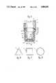
- FIGS. 6, 7 and 8are alternative cross-sectional configurations of the piston and cylinder.
- a filtering device embodying the present inventionincludes a hollow chamber, e.g., a cylinder C and a hollow piston P having central axes A c and A p respectively.
- the piston and cylindermay be made of plastic or other appropriate material.
- the cylinderis open at one end 10 and closed at the other end 12. It has a constant internal diameter or cross section 14 for a majority of its length and adjacent the closed end there is an internal diameter or cross-section 16 of reduced diameter. The area of the reduced cross-section 16 intersects the remainder of the cylinder 14 at a frusto conical annular surface 18.
- projections 20Spaced equidistantly around the interior diameter of the cylinder C are projections 20, the function of which will be explained in greater detail hereinafter.
- the piston Phas an open end 30 and a partially open end 32.
- the piston Phas a hollow cylindrical constant diameter or cross section portion 34 for more than half of its length and a portion of reduced external diameter or cros-section 36, which is adjacent the partially open end 32.
- the reduced diameter portion 36terminates in a frusto conical portion 38, which is formed on the same angle as the frusto conical portion 18 of the cylinder C.
- a groove 40is formed adjacent the frusto conical portion 38 and includes a second frusto conical portion 42 intersecting the first portion 38 to form, in effect, a projecting angular ridge 44.
- the portion 42together with an annular ring 46, defines the groove 40.
- the partially opened end of the cylinderincludes a circular recessed opening 50 within which there is a circular opening 52 in a wall portion 54.
- the openingis partially closed by a grid 56 illustrated as cruciform legs.
- piston P and the cylinder Chave been described as being cylindrical, it will be understood that they can assume other cross-sectional shapes as well. For example, they could be triangular as shown schematically in FIG. 6, rectangular or square as shown schematically in FIG. 7, or polygonal as shown schematically in FIG. 8, a hexigon being illustrated.
- the cylindrical formis preferred because of ease of manufacture, but as long as the piston and cylinder each have the same cross-sectional configuration, (the piston being smaller, of course), with their walls being parallel or symmetrical to their axes A c A p respectively, they are within the scope of the present invention.
- FIG. 5the piston and cylinder are shown in assembled form.
- an O-ring 60is placed in the annular groove 40 and a wafer-like, non-woven, plastic support 62 in the form of a circular disc, is placed in the circular recess 50 in the partially open end of the piston.
- This support member 60abuts the cruciform legs 56.
- a disc of filter material 64 of the desired pore sizeis placed against the support 62.
- the filter 64 and the support 60are held in place by a plastic retaining ring 66, which fits in the opening 50 and which may be heat sealed in permanent position.
- Filter material usable with this inventionis readily available commercially. The selection of the filter is dependent upon the material being filtered and the degree of filtration desired.
- the frusto conical portions 18 and 42assure that any liquid in the cylinder will be free to flow toward the closed end thereof and not be trapped or retained by an angle of 90°s or less.
- the gapthere is a cylindrical gap defined by the reduced internal diameter 16 of the cylinder and the reduced external diameter 36 of the piston.
- This gapis constant lengthwise of the axes A c and A p of the assembled piston and cylinder and is from about 0.01 to 0.08 inches. The exact dimension is selected in accordance with the viscosity of the material to be filtered, the greater the viscosity the greater the gap.
- the gapextends between closed bottom 22 of the cylinder and the lower most surface 25 of the filter end of the piston, the bottom of the retaining ring 66 being a continuation of this surface. This is accomplished by the spaced projections 24 projecting from the bottom 24 of the cylinder. The spacing being essentially the same dimension as the gap.
- the members 24act as stop means for limiting how close the piston can approach the closed end of the cylinder.
- annular ring 44has passed beneath the projections 20 (one being shown in FIG. 5). Because of the flexibility of the material from which the piston and cylinder are made, the ring 44 snaps past the projections 20 and, having done so, retains the piston at the closed end of the cylinder. Being flexible, these cooperative retaining means are releasable.
- the filtering deviceoperates in the following manner.
- a biological sample to be analyzedis taken by a cotton swab or the like.
- An extraction bufferis poured into the cylinder and the cotton swab is immersed to extract the sample.
- the swabis then removed.
- the pistonis inserted and is urged downwardly or toward the closed end 12 of the cylinder. Air, which is trapped because of the seal 60 between the piston and the cylinder, becomes compressed and flows upwardly through the filter 64 and its support 64. Air will continue to pass through the filter 64 until such time as the filter touches the top of the liquid. Then wicking will take place wetting the entire filter.
- the filtratemay then be removed from the piston for analysis with substantially no wastage.
- the piston and cylindermay be assembled as shown in FIG. 5 with the unfiltered solution being poured into the hollow piston with the piston then withdrawn from the cylinder to create a vacuum at the closed end of the cylinder and the filtration process will be reversed.
- the pistonmay be completely removed from the cylinder leaving only the filtrate in the cylinder.
Landscapes
- Chemical & Material Sciences (AREA)
- Chemical Kinetics & Catalysis (AREA)
- Filtration Of Liquid (AREA)
- Sampling And Sample Adjustment (AREA)
Abstract
Description
Claims (26)
Priority Applications (3)
| Application Number | Priority Date | Filing Date | Title |
|---|---|---|---|
| US07/052,780US4800020A (en) | 1987-05-21 | 1987-05-21 | Piston filtering device |
| JP63122174AJPH01127011A (en) | 1987-05-21 | 1988-05-20 | Filter apparatus |
| EP88304650AEP0292329A3 (en) | 1987-05-21 | 1988-05-23 | Filtering device |
Applications Claiming Priority (1)
| Application Number | Priority Date | Filing Date | Title |
|---|---|---|---|
| US07/052,780US4800020A (en) | 1987-05-21 | 1987-05-21 | Piston filtering device |
Publications (1)
| Publication Number | Publication Date |
|---|---|
| US4800020Atrue US4800020A (en) | 1989-01-24 |
Family
ID=21979841
Family Applications (1)
| Application Number | Title | Priority Date | Filing Date |
|---|---|---|---|
| US07/052,780Expired - Fee RelatedUS4800020A (en) | 1987-05-21 | 1987-05-21 | Piston filtering device |
Country Status (3)
| Country | Link |
|---|---|
| US (1) | US4800020A (en) |
| EP (1) | EP0292329A3 (en) |
| JP (1) | JPH01127011A (en) |
Cited By (20)
| Publication number | Priority date | Publication date | Assignee | Title |
|---|---|---|---|---|
| US4891134A (en)* | 1988-01-25 | 1990-01-02 | Abbott Laboratories | Sample filtration device |
| US4990253A (en)* | 1988-01-25 | 1991-02-05 | Abbott Laboratories | Fluid sample filtration device |
| US5114858A (en)* | 1990-06-26 | 1992-05-19 | E. I. Du Pont De Nemours And Company | Cellular component extraction process in a disposable filtration vessel |
| US5549816A (en)* | 1995-10-31 | 1996-08-27 | Hach Company | Re-usable piston filter system |
| US5658463A (en)* | 1993-03-05 | 1997-08-19 | Strategic Diagnostics, Inc. | Process for extraction of analytes from solid and materials and filtration |
| US6478966B2 (en) | 2000-11-22 | 2002-11-12 | Nanning Maple Leaf Pharmaceutical Co., Ltd. | System for extracting tetrodotoxin |
| US6582665B2 (en)* | 2001-01-25 | 2003-06-24 | Biomedical Polymers, Inc. | Universal collection and transfer system |
| US20040033170A1 (en)* | 2000-03-22 | 2004-02-19 | Dewalch Binz | Method and apparatus for processing substances in a single container |
| US20040242492A1 (en)* | 2001-08-30 | 2004-12-02 | Tord Inghardt | Mandelic acid derivatives and their use as thrombin inhibitors |
| US20060145532A1 (en)* | 2004-12-16 | 2006-07-06 | Bernd Groll | Electrohydraulically regulatable vehicle brake system with traction control device |
| US7135117B2 (en) | 2001-05-31 | 2006-11-14 | Pall Corporation | Well for processing a fluid |
| US20080091147A1 (en)* | 2004-06-23 | 2008-04-17 | Hee Young Lee | Syringe Piston Using in Fat Transplantation |
| US20080260593A1 (en)* | 2000-03-22 | 2008-10-23 | Dewalch Norman Binz | Method and apparatus for processing substances in a single container |
| US20090238725A1 (en)* | 2008-03-21 | 2009-09-24 | Ellis Samuel A | Filter vial |
| US20120118823A1 (en)* | 2010-06-24 | 2012-05-17 | Southern Illinois University Carbondale | Organosilicate based filtration system |
| WO2012085006A1 (en) | 2010-12-21 | 2012-06-28 | Ge Healthcare Uk Limited | Filtration device and method |
| US8322539B1 (en) | 2012-03-02 | 2012-12-04 | Scientific Plastic Products, Inc. | Filter vial |
| US10369500B2 (en)* | 2013-10-02 | 2019-08-06 | Allergan, Inc. | Fat processing system |
| US20220162536A1 (en)* | 2019-09-09 | 2022-05-26 | Murata Manufacturing Co., Ltd. | Concentration device and concentration method |
| US12128334B2 (en)* | 2018-09-05 | 2024-10-29 | Kin Mun Chin | Filter press with threadably advanced filtrate receiving plunger |
Families Citing this family (3)
| Publication number | Priority date | Publication date | Assignee | Title |
|---|---|---|---|---|
| EP2695656A1 (en)* | 2012-08-09 | 2014-02-12 | F. Hoffmann-La Roche AG | Method and separation device for separating a filtrate from a sample liquid |
| US20150076069A1 (en)* | 2013-09-13 | 2015-03-19 | Scientific Plastic Products, Inc. | Filter vial with limited piston stroke |
| CN104096400B (en)* | 2014-07-31 | 2016-04-20 | 吴小龙 | A kind of piston filter device |
Citations (11)
| Publication number | Priority date | Publication date | Assignee | Title |
|---|---|---|---|---|
| US3512940A (en)* | 1968-12-30 | 1970-05-19 | Justin J Shapiro | Test tube filter device |
| US3802843A (en)* | 1971-05-28 | 1974-04-09 | American Hospital Supply Corp | Fluid testing apparatus |
| US4035294A (en)* | 1975-05-23 | 1977-07-12 | Denver Chemical Manufacturing Company | Pressure differential filtering device and method |
| US4057499A (en)* | 1973-03-09 | 1977-11-08 | Buono Frank S | Apparatus and method for separation of blood |
| US4131549A (en)* | 1977-05-16 | 1978-12-26 | Ferrara Louis T | Serum separation device |
| US4189385A (en)* | 1977-05-03 | 1980-02-19 | Greenspan Donald J | Method and apparatus for separating serum or plasma from the formed elements of the blood |
| US4454231A (en)* | 1979-12-12 | 1984-06-12 | Technion Research And Development Foundation, Ltd. | Method and device for mass transfer operation in immunoassays and other applications |
| US4456690A (en)* | 1981-07-20 | 1984-06-26 | Technion Research And Development Foundation, Ltd. | Non-centrifugation method for immunoassay of materials |
| US4510058A (en)* | 1982-08-15 | 1985-04-09 | Technion Research & Development Foundation, Ltd. | Method for a new type of chromatography and device therefor |
| US4588556A (en)* | 1983-12-05 | 1986-05-13 | Walter Sarstedt Kunststoff-Spritzgusswerk | Arrangement for placing a separating gel between two phases located in a sample tube |
| US4643981A (en)* | 1983-11-09 | 1987-02-17 | Akzo N.V. | Pressure filtration system |
Family Cites Families (4)
| Publication number | Priority date | Publication date | Assignee | Title |
|---|---|---|---|---|
| US3846077A (en)* | 1972-09-18 | 1974-11-05 | P Ohringer | Liquid sample collection tube |
| US4035150A (en)* | 1975-09-24 | 1977-07-12 | The United States Of America As Represented By The Secretary Of The Department Of Health, Education And Welfare | Test for occult blood in an emulsified aqueous/organic system |
| US4214993A (en)* | 1978-04-03 | 1980-07-29 | E. I. Du Pont De Nemours And Company | Apparatus for separating fluids |
| DE3342695A1 (en)* | 1982-11-26 | 1984-05-30 | Sartorius GmbH, 3400 Göttingen | Apparatus for static membrane filtration |
- 1987
- 1987-05-21USUS07/052,780patent/US4800020A/ennot_activeExpired - Fee Related
- 1988
- 1988-05-20JPJP63122174Apatent/JPH01127011A/enactivePending
- 1988-05-23EPEP88304650Apatent/EP0292329A3/ennot_activeWithdrawn
Patent Citations (12)
| Publication number | Priority date | Publication date | Assignee | Title |
|---|---|---|---|---|
| US3512940A (en)* | 1968-12-30 | 1970-05-19 | Justin J Shapiro | Test tube filter device |
| US3802843A (en)* | 1971-05-28 | 1974-04-09 | American Hospital Supply Corp | Fluid testing apparatus |
| US4057499A (en)* | 1973-03-09 | 1977-11-08 | Buono Frank S | Apparatus and method for separation of blood |
| US4035294A (en)* | 1975-05-23 | 1977-07-12 | Denver Chemical Manufacturing Company | Pressure differential filtering device and method |
| US4189385A (en)* | 1977-05-03 | 1980-02-19 | Greenspan Donald J | Method and apparatus for separating serum or plasma from the formed elements of the blood |
| US4131549A (en)* | 1977-05-16 | 1978-12-26 | Ferrara Louis T | Serum separation device |
| US4454231A (en)* | 1979-12-12 | 1984-06-12 | Technion Research And Development Foundation, Ltd. | Method and device for mass transfer operation in immunoassays and other applications |
| US4456690A (en)* | 1981-07-20 | 1984-06-26 | Technion Research And Development Foundation, Ltd. | Non-centrifugation method for immunoassay of materials |
| US4587221A (en)* | 1981-07-20 | 1986-05-06 | Technion Research & Development Foundation, Ltd. | Non-centrifugation method for immunoassay of materials |
| US4510058A (en)* | 1982-08-15 | 1985-04-09 | Technion Research & Development Foundation, Ltd. | Method for a new type of chromatography and device therefor |
| US4643981A (en)* | 1983-11-09 | 1987-02-17 | Akzo N.V. | Pressure filtration system |
| US4588556A (en)* | 1983-12-05 | 1986-05-13 | Walter Sarstedt Kunststoff-Spritzgusswerk | Arrangement for placing a separating gel between two phases located in a sample tube |
Cited By (35)
| Publication number | Priority date | Publication date | Assignee | Title |
|---|---|---|---|---|
| US4891134A (en)* | 1988-01-25 | 1990-01-02 | Abbott Laboratories | Sample filtration device |
| US4990253A (en)* | 1988-01-25 | 1991-02-05 | Abbott Laboratories | Fluid sample filtration device |
| US5114858A (en)* | 1990-06-26 | 1992-05-19 | E. I. Du Pont De Nemours And Company | Cellular component extraction process in a disposable filtration vessel |
| US5330916A (en)* | 1990-06-26 | 1994-07-19 | E. I. Du Pont De Nemours And Company | Cellular component extraction apparatus and disposable vessel useful therein |
| US5658463A (en)* | 1993-03-05 | 1997-08-19 | Strategic Diagnostics, Inc. | Process for extraction of analytes from solid and materials and filtration |
| US5549816A (en)* | 1995-10-31 | 1996-08-27 | Hach Company | Re-usable piston filter system |
| US20040033170A1 (en)* | 2000-03-22 | 2004-02-19 | Dewalch Binz | Method and apparatus for processing substances in a single container |
| US20080260593A1 (en)* | 2000-03-22 | 2008-10-23 | Dewalch Norman Binz | Method and apparatus for processing substances in a single container |
| US20110044866A1 (en)* | 2000-03-22 | 2011-02-24 | Dewalch Norman Binz | Method and Apparatus for Processing Substances in a Single Container |
| US6478966B2 (en) | 2000-11-22 | 2002-11-12 | Nanning Maple Leaf Pharmaceutical Co., Ltd. | System for extracting tetrodotoxin |
| US6582665B2 (en)* | 2001-01-25 | 2003-06-24 | Biomedical Polymers, Inc. | Universal collection and transfer system |
| US7135117B2 (en) | 2001-05-31 | 2006-11-14 | Pall Corporation | Well for processing a fluid |
| US20070059218A1 (en)* | 2001-05-31 | 2007-03-15 | Pall Corporation | Well for processing a fluid |
| US7371325B2 (en) | 2001-05-31 | 2008-05-13 | Pall Corporation | Well for processing a fluid |
| US20040242492A1 (en)* | 2001-08-30 | 2004-12-02 | Tord Inghardt | Mandelic acid derivatives and their use as thrombin inhibitors |
| US7819846B2 (en)* | 2004-06-23 | 2010-10-26 | Medikan Co., Ltd. | Syringe piston using in fat transplantation |
| US20080091147A1 (en)* | 2004-06-23 | 2008-04-17 | Hee Young Lee | Syringe Piston Using in Fat Transplantation |
| US20060145532A1 (en)* | 2004-12-16 | 2006-07-06 | Bernd Groll | Electrohydraulically regulatable vehicle brake system with traction control device |
| US7731304B2 (en)* | 2004-12-16 | 2010-06-08 | Robert Bosch Gmbh | Electrohydraulically regulatable vehicle brake system with traction control device |
| US20090238725A1 (en)* | 2008-03-21 | 2009-09-24 | Ellis Samuel A | Filter vial |
| US8383066B2 (en) | 2008-03-21 | 2013-02-26 | Scientific Plastic Products, Inc. | Filter vial |
| US9409165B2 (en) | 2008-03-21 | 2016-08-09 | Scientific Plastic Products, Inc. | Filter vial |
| US7790117B2 (en) | 2008-03-21 | 2010-09-07 | Scientific Plastic Products, Inc. | Filter vial |
| US8211384B2 (en) | 2008-03-21 | 2012-07-03 | Scientific Plastic Products, Inc. | Filter vial |
| US8925734B2 (en) | 2008-03-21 | 2015-01-06 | Scientific Plastic Products, Inc. | Filter vial |
| US20120118823A1 (en)* | 2010-06-24 | 2012-05-17 | Southern Illinois University Carbondale | Organosilicate based filtration system |
| WO2012085007A1 (en) | 2010-12-21 | 2012-06-28 | Ge Healthcare Uk Limited | Filtration device and method |
| WO2012085006A1 (en) | 2010-12-21 | 2012-06-28 | Ge Healthcare Uk Limited | Filtration device and method |
| US9919248B2 (en) | 2010-12-21 | 2018-03-20 | Ge Healthcare Uk Limited | Filtration device and method |
| US8728329B2 (en)* | 2012-03-02 | 2014-05-20 | Scientific Plastic Products, Inc. | Method for filtering fluid using a filter vial |
| US8322539B1 (en) | 2012-03-02 | 2012-12-04 | Scientific Plastic Products, Inc. | Filter vial |
| US8978896B2 (en) | 2012-03-02 | 2015-03-17 | Scientific Plastic Products, Inc. | Method for filtering liquid using a filter vial |
| US10369500B2 (en)* | 2013-10-02 | 2019-08-06 | Allergan, Inc. | Fat processing system |
| US12128334B2 (en)* | 2018-09-05 | 2024-10-29 | Kin Mun Chin | Filter press with threadably advanced filtrate receiving plunger |
| US20220162536A1 (en)* | 2019-09-09 | 2022-05-26 | Murata Manufacturing Co., Ltd. | Concentration device and concentration method |
Also Published As
| Publication number | Publication date |
|---|---|
| EP0292329A2 (en) | 1988-11-23 |
| JPH01127011A (en) | 1989-05-19 |
| EP0292329A3 (en) | 1989-07-19 |
Similar Documents
| Publication | Publication Date | Title |
|---|---|---|
| US4800020A (en) | Piston filtering device | |
| US3870639A (en) | Filtering device | |
| US3969250A (en) | Apparatus for preparing liquid samples for analysis in automatic analyzers | |
| US4210623A (en) | Fluid collection apparatus | |
| DE69429783T2 (en) | DEVICE AND METHOD FOR COLLECTING CELLS FROM A LIQUID SAMPLE | |
| US5514341A (en) | Feces-sampling transport container | |
| US3879295A (en) | Vacutainer with positive separation barrier | |
| DE69912785T2 (en) | DEVICE FOR FILTRATION AND EXTRACTION AND METHOD FOR YOUR USE | |
| US4962044A (en) | Test tube filter/dispenser apparatus and method | |
| EP0283663B1 (en) | Blood separation system | |
| US3687296A (en) | Fluid separator | |
| US3693804A (en) | Pressure differential filtering apparatus and method | |
| US3954614A (en) | Serum skimmer and filter separation unit | |
| US3837376A (en) | Blood serum collection tube and method | |
| JPH0455265B2 (en) | ||
| US3865731A (en) | Filter skimming device | |
| US3761408A (en) | Method and apparatus for separating blood constituent components | |
| JP2001509590A (en) | Apparatus and method for separating cellular material from tissue clumps and / or fluid | |
| JPH02248836A (en) | Method and apparatus for separating and collecting particle from fluid for medical diagnosis | |
| EP0734767A2 (en) | Container for treating fluids with reduced contamination risk | |
| US4792398A (en) | Manual vacuum filtration device | |
| EP0734768A1 (en) | Method of binding a biological substance | |
| JP4113464B2 (en) | Blood test container and blood test method | |
| JP2008279195A (en) | Blood separation filter device | |
| US3732981A (en) | Filtration column |
Legal Events
| Date | Code | Title | Description |
|---|---|---|---|
| AS | Assignment | Owner name:XYDEX CORPORATION, 4 ALFRED CIRCLE, BEDFORD, MA., Free format text:ASSIGNMENT OF ASSIGNORS INTEREST.;ASSIGNOR:BOUDREAU, RONALD R.;REEL/FRAME:004716/0376 Effective date:19870521 Owner name:XYDEX CORPORATION, 4 ALFRED CIRCLE, BEDFORD, MA., Free format text:ASSIGNMENT OF ASSIGNORS INTEREST.;ASSIGNOR:KIGER, VIRGINIA S.;REEL/FRAME:004716/0374 Effective date:19870521 Owner name:XYDEX CORPORATION, 4 ALFRED CIRCLE, BEDFORD, MA., Free format text:ASSIGNMENT OF ASSIGNORS INTEREST.;ASSIGNOR:SAVAS, PETER G.;REEL/FRAME:004716/0372 Effective date:19870521 | |
| AS | Assignment | Owner name:GENEX CORPORATION, DELAWARE Free format text:MERGER;ASSIGNOR:XYDEX CORPORATION, A CORP. OF MA;REEL/FRAME:005454/0018 Effective date:19881222 | |
| AS | Assignment | Owner name:WHATMAN CORPORATION, 9 BRIDEWELL PLACE, CLIFTON, N Free format text:ASSIGNMENT OF ASSIGNORS INTEREST.;ASSIGNOR:GENEX CORPORATION, A DE CORP.;REEL/FRAME:005581/0385 Effective date:19901114 | |
| REMI | Maintenance fee reminder mailed | ||
| LAPS | Lapse for failure to pay maintenance fees | ||
| FP | Lapsed due to failure to pay maintenance fee | Effective date:19930124 | |
| STCH | Information on status: patent discontinuation | Free format text:PATENT EXPIRED DUE TO NONPAYMENT OF MAINTENANCE FEES UNDER 37 CFR 1.362 |