US4799625A - Method and apparatus for adjusting a shear bar relative to a cutter head - Google Patents
Method and apparatus for adjusting a shear bar relative to a cutter headDownload PDFInfo
- Publication number
- US4799625A US4799625AUS07/046,011US4601187AUS4799625AUS 4799625 AUS4799625 AUS 4799625AUS 4601187 AUS4601187 AUS 4601187AUS 4799625 AUS4799625 AUS 4799625A
- Authority
- US
- United States
- Prior art keywords
- shear bar
- cutter head
- motor
- bar
- sensing
- Prior art date
- Legal status (The legal status is an assumption and is not a legal conclusion. Google has not performed a legal analysis and makes no representation as to the accuracy of the status listed.)
- Ceased
Links
- 238000000034methodMethods0.000titleclaimsdescription14
- 238000012360testing methodMethods0.000claimsabstractdescription46
- 230000035945sensitivityEffects0.000claimsabstractdescription10
- 230000001939inductive effectEffects0.000claimsabstractdescription5
- 230000002457bidirectional effectEffects0.000claimsdescription7
- 239000000463materialSubstances0.000claimsdescription5
- 230000004044responseEffects0.000claimsdescription4
- 238000005070samplingMethods0.000claimsdescription2
- 101000599778Homo sapiens Insulin-like growth factor 2 mRNA-binding protein 1Proteins0.000description7
- 101000988591Homo sapiens Minor histocompatibility antigen H13Proteins0.000description7
- 101000960626Homo sapiens Mitochondrial inner membrane protease subunit 2Proteins0.000description7
- 101000828788Homo sapiens Signal peptide peptidase-like 3Proteins0.000description7
- 102100029083Minor histocompatibility antigen H13Human genes0.000description7
- 102100023501Signal peptide peptidase-like 3Human genes0.000description7
- 238000006243chemical reactionMethods0.000description6
- 101100328463Mus musculus Cmya5 geneProteins0.000description5
- 238000000176thermal ionisation mass spectrometryMethods0.000description5
- 238000013055trapped ion mobility spectrometryMethods0.000description5
- 239000004459forageSubstances0.000description3
- 230000007246mechanismEffects0.000description3
- 239000013078crystalSubstances0.000description2
- 230000000994depressogenic effectEffects0.000description2
- 238000010586diagramMethods0.000description2
- 238000012544monitoring processMethods0.000description2
- 230000002093peripheral effectEffects0.000description2
- 241001124569LycaenidaeSpecies0.000description1
- 230000000881depressing effectEffects0.000description1
- 238000001514detection methodMethods0.000description1
- 230000000694effectsEffects0.000description1
- 230000000977initiatory effectEffects0.000description1
- 238000012986modificationMethods0.000description1
- 230000004048modificationEffects0.000description1
- 230000003287optical effectEffects0.000description1
- 230000000737periodic effectEffects0.000description1
- 238000002360preparation methodMethods0.000description1
- 238000006467substitution reactionMethods0.000description1
- 230000000007visual effectEffects0.000description1
- 239000002699waste materialSubstances0.000description1
- 238000004804windingMethods0.000description1
Images


Classifications
- A—HUMAN NECESSITIES
- A01—AGRICULTURE; FORESTRY; ANIMAL HUSBANDRY; HUNTING; TRAPPING; FISHING
- A01F—PROCESSING OF HARVESTED PRODUCE; HAY OR STRAW PRESSES; DEVICES FOR STORING AGRICULTURAL OR HORTICULTURAL PRODUCE
- A01F29/00—Cutting apparatus specially adapted for cutting hay, straw or the like
- A01F29/09—Details
- A—HUMAN NECESSITIES
- A01—AGRICULTURE; FORESTRY; ANIMAL HUSBANDRY; HUNTING; TRAPPING; FISHING
- A01D—HARVESTING; MOWING
- A01D34/00—Mowers; Mowing apparatus of harvesters
- A01D34/01—Mowers; Mowing apparatus of harvesters characterised by features relating to the type of cutting apparatus
- A01D34/412—Mowers; Mowing apparatus of harvesters characterised by features relating to the type of cutting apparatus having rotating cutters
- A01D34/42—Mowers; Mowing apparatus of harvesters characterised by features relating to the type of cutting apparatus having rotating cutters having cutters rotating about a horizontal axis, e.g. cutting-cylinders
- A01D34/62—Other details
- A—HUMAN NECESSITIES
- A01—AGRICULTURE; FORESTRY; ANIMAL HUSBANDRY; HUNTING; TRAPPING; FISHING
- A01F—PROCESSING OF HARVESTED PRODUCE; HAY OR STRAW PRESSES; DEVICES FOR STORING AGRICULTURAL OR HORTICULTURAL PRODUCE
- A01F29/00—Cutting apparatus specially adapted for cutting hay, straw or the like
- A01F29/09—Details
- A01F29/095—Mounting or adjusting of knives
- A—HUMAN NECESSITIES
- A01—AGRICULTURE; FORESTRY; ANIMAL HUSBANDRY; HUNTING; TRAPPING; FISHING
- A01D—HARVESTING; MOWING
- A01D2101/00—Lawn-mowers
Definitions
- the present inventionrelates to forage harvesters and more particularly to a method and apparatus for automatically adjusting the position of a shear bar so that it is parallel to a rotating cutter head, no operator intervention being required except for actuating a switch to initiate the adjustment operation.
- German DE No. 33 45 749Adiscloses the use of a single motor for simultaneously driving linkages connected to both ends of a harvester shear bar to rotating cutter head. Because both linkages are driven by a single motor, and are thus driven equally, it is not possible to automatically adjust the shear bar if it is not initially parallel to the cutter head and parallelism must be effected manually before the automatic adjustment may be accomplished.
- German OS No. 30 10 416discloses the use of an acoustic or optical non-contact sensor for monitoring the gap between the fixed and moving blades of a harvester.
- the sensormonitors the gap between the fixed and moving blades by sensing the proximity of the moving blades and if the gap varies beyond predetermined limits the harvester operation is stopped. No provision is made for utilizing the sensor output to adjust the gap.
- the vibration sensorIn an automatic adjustment system wherein contact between the shear bar and rotating cutter head is sensed to control the adjustment, it is essential that the vibration sensor be in good operating condition. If the sensor or its associated wiring is faulty, or the cutter head is not rotating, the adjustment mechanism may drive the shear bar too far toward the blades of the rotating cutter head thus damaging the shear bar, cutter blades and/or adjustment drive mechanism.
- the operability of the vibration sensoris repeatedly checked before and during a shear bar adjustment operation and checks are made to insure that the cutter head is rotating at or above a predetermined minimum speed.
- Background noisethat is, the vibrations induced by normal harvester operation, is particularly troublesome when vibration sensors are utilized in an automatic shear bar adjustment system.
- meansare provided for adapting the threshold of the vibration detection system in accordance with the level of background noise so that vibrations resulting from contact between the shear bar and rotating cutter blades may be reliably distinguished from vibrations resulting from normal harvester operation.
- An object of the present inventionis to provide a method and apparatus for automatically adjusting a shear bar relative to a rotating cutter head even though the shear bar and cutter head may not be parallel to each other prior to initiation of the adjustment operation.
- An object of the inventionis to provide a method and apparatus for adjusting a shear bar relative to a rotating cutter head by alternately energizing a first or a second drive motor to alternately move a first or a second end of the shear bar relative to the rotating cutter head.
- Another object of the inventionis to provide an adjusting apparatus including first and second bidirectional motors each attached to a shear bar near a respective end thereof, an acoustic sensor mounted on the shear bar support for sensing vibrations induced when a rotating cutter head contacts the shear bar, and an electrical control circuit or microprocessor initiated by actuation of a switch for automatically controlling the motors in response to vibrations sensed by the sensor, to thereby adjust the shear bar relative to the cutter head.
- the microprocessorPrior to and during the adjusting procedure the microprocessor senses the speed of rotation of the cutter head and initiates movement of the shear bar only when the cutter head is rotating at or above some predetermined speed.
- a further object of the inventionis to provide an electrical control circuit as described above wherein the microprocessor not only controls the motors but also controls the testing of the operability of the sensor and adjusts its sensitivity.
- a knocker or impact elementis mounted on the shear bar support to induce vibrations therein in response to pulses generated under the control of the microprocessor. The vibrations are sensed by the sensor and the resulting electrical signal applied to an analog to digital converter to develop a digital indication of the sensor output. The microprocessor then compares the digital indication with a reference value and halts the adjusting procedure if the digital indication does not exceed the reference value.
- Another object of the inventionis to provide an electrical control circuit as described above and further including means for adjusting the sensitivity of the control circuit to output signals from the knock sensor.
- the sensitivityis adjusted by sensing the "noise" vibrations in the shear bar support and developing digital indication of the noise. During the adjusting procedure this digital indication is added to a safety factor value and the output of the knock sensor (after analog to digital conversion) is compared to the sum.
- the magnitude of the output signal from the knock sensor required to indicate impact between the shear bar and cutter headvaries depending on the noise vibrations induced in the shear bar by normal harvester operation.
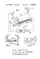
- FIG. 1schematically illustrates an adjustment control system for automatically controlling the adjustment of a shear bar relative to a rotating cutter head
- FIG. 2is a diagram useful in explaining the method of adjusting the shear bar
- FIG. 3illustrates the mounting of an impact element and a vibration sensor on a shear bar support
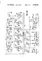
- FIGS. 4A and 4Bwhen arranged as shown in FIG. 4C, comprise a circuit diagram of the electrical controls for controlling the shear bar adjustment and the testing and sensitivity adjustment of the vibration sensor;
- FIG. 5shows the knock sensor output circuits and the circuits for applying reference signals to the analog to digital converter
- FIG. 6shows the INITIALIZE routine
- FIG. 7shows the READY routine
- FIG. 8shows the NMIR routine
- FIG. 9shows the TSTGEN routine
- FIGS. 10A and 10Bshow the GETNOI routine
- FIG. 11shows the PULOUT routine
- FIGS. 12A-12Dshow the ADJUST routine
- FIG. 13shows the PULFOUT subroutine.
- FIG. 1schematically illustrates a cutting apparatus comprising a rotating cutter head 100 and an adjustable but fixed shear bar 102.
- the cutting apparatusmay be the cutter head and shear bar of a forage harvester as illustrated in commonly assigned U.S. application Ser. No. 783,391.
- the shear bar 102is mounted on a support bar 104 but is movable with respect to the support bar by actuation of linkages such as a pair of lead screws 106, 108.
- the cutter headcarries a plurality of knives which, as the cutter head rotates, cooperate with the shear bar 102 to cut material passing between the cutter head and the shear bar.
- a first bidirectional motor 110drives lead screw 106 which is linked to a first end A of the shear bar.
- a second bidirectional motor 112drives lead screw 108 which is linked to a second end B of the shear bar.
- Adjustment of the shear bar 102 relative to the cutter head 100is accomplished with the cutter head rotating.
- a tachometer 114senses rotation of the cutter head shaft and produces a sequence of pulses indicating the cutter head speed which is applied to an electrical control circuit 116. Adjustment is accomplished by sensing vibrations, or the absence of vibrations in the support bar 104 resulting from contact, or the lack of contact, between the shear bar 102 and the knives of the rotating cutter head.
- a vibration sensor 118which may be a crystal, is attached to the support bar 104.
- the support barhas an internally threaded hole 120 (FIG. 3) for receiving a threaded mounting stud provided on the crystal mount.
- a solenoid-actuated knocker 122is provided for determining the operability of the knock sensor.
- the knockerhas a threaded mounting stud which secures the knocker to an internally threaded hole 124 in the support bar 104.
- the solenoidhas a spring-biased armature which carries an impact element 126 at its end. When the solenoid is energized it drives the impact element 126 into contact with the support bar 104, inducing vibrations in the support bar which are sensed by the sensor 118.
- the electrical controls 116pulse the knocker 122 and analyze the signals returned by the sensor 118.
- a push-button switch 128is provided on a control panel near the operator. Each time the operator actuates switch 128, the electrical control circuit 116 checks the operability of sensor 118 as well as its sensitivity, checks to determine that the cutter head is rotating and selectively energizes first one of the motors 110, 112 and then the other until the cutter bar 102 is essentially parallel to the cutter head 100 and spaced therefrom by no more than a small predetermined distance on the order of a few thousandths of an inch.
- the electrical control circuits 116are illustrated in FIGS. 4A and 4B and include a microprocessor 200, an EPROM 202, an analog to digital converter (ADC) 204, a peripheral interface adapter (PIA) 206, a versatile interface adapter (VIA) 208, an address decoder or selector 210 and a watch dog circuit 212. All units except the watch dog circuit are interconnected by an 8-bit bidirectional data bus 214 and/or a 16-bit address bus 216.
- ADCanalog to digital converter
- PDAperipheral interface adapter
- VIPversatile interface adapter
- VIA 208Since the details of the VIA 208, microprocessor 200, EPROM 202, ADC 204, PIA 206, and address decoder 210 are well known in the art, they are not described in detail herein but a brief description of each is given below.
- the microprocessor 200may be a Motorola type 6802 microprocessor including an internal memory for limited storage of data during a microprocessor operation.
- the microprocessorhas eight input/output terminals D7-D ⁇ which are connected to the data bus 214 and sixteen output terminals A15-A ⁇ for supplying an address generated within the microprocessor to the address bus 216.
- the microprocessordrives the signal R/W on lead 218 to logic ⁇ and when the data register is to receive a byte of data from the data bus the microprocessor causes the signal R/W to go to logic 1.
- VMAValid Memory Address
- Microprocessor 200has a non-maskable interrupt (NMI) input terminal. A low-going signal at this terminal causes the microprocessor to initiate a non-maskable interrupt sequence.
- the microprocessoralso has a reset input terminal R and when the signal on lead 230 goes to low the registers within the microprocessor are cleared and the microprocessor becomes inactive. When the signal at terminal R goes high it causes the microprocessor to begin a restart sequence.
- NMInon-maskable interrupt
- Address bus bits A15-A13are connected to input terminals of the address decoder 210. Each time the microprocessor outputs a signal on lead 220, it enables the address decoder to decode the three address bits and produce a signal on one of the leads 223-226.
- the lead 223is connected to the CS2 input of VIA 208.
- Lead 224is connected to the OE and CE inputs of EPROM 202.
- Lead 225is connected to the CS input of ADC 204 while lead 226 is connected to the CS2 input of PIA 206.
- the EPROM 202may be a type 2764 capable of storing 8K 8-bit bytes. When the signal on lead 224 is low the location in the EPROM specified by the address applied to the EPROM from bus 216 is accessed. The location is either written to from the microprocessor, or read out to the microprocessor, depending upon whether the signal R/W is low or high, respectively. EPROM 202 stores data and the program which is executed by the microprocessor.
- the VIA 208may be a type 6522 such as that manufactured by Rockwell or Synertek. As disclosed at page 2526-2530 of the publication IC Master 1980, published by United Technical Publications, the VIA 208 includes 16 addressable registers and interval timers or counters. These registers and interval timers are addressed by applying an address from the four low order of bits of the address bus 216 to the register select input RS3-RS ⁇ . Data is read from, or entered into the registers and counters through data terminals D7-D ⁇ which are connected to the data bus 214.
- the VIAis enabled only when the microprocessor outputs a hexadecimal address, the high order bits of which cause the address decoder 210 to produce a low signal on lead 223 which enables the chip select CS2 input of the VIA.
- the register or counter which is accessedis determined by the four low order bits of the address bus which are applied to register select inputs RS3-RS ⁇ of the VIA.
- the accessed register or counteris either read from or written into depending upon whether the microprocessor 200 outputs a high or low level signal, respectively, on lead 218 to R/W terminal of the VIA.
- the ⁇ 2 input of the VIAis a clocking input and is used to trigger data transfers. It is connected by lead 222 to the E terminal of the microprocessor.
- All circuits within VIA 208are reset when the signal RES on lead 230 goes low.
- the VIA 208produces an output signal CB2 which is used for control purposes.
- the microprocessor programperiodically sends a byte of control information to VIA 208 to toggle CB2 and pulse watch dog circuit 212.
- the watch dog circuitmay be two monostable multivibrators connected in series. Periodic pulses produced on lead 232 by the VIA periodically reset the watch dog circuit so that its output remains inactive. If the program should fail to send signals to the VIA 208 so that lead 232 is pulsed, the watch dog circuit times out and emits an output signal to reset the microprocessor, the VIA and the PIA 206.
- the watch dog circuit 212also has an input 234 which is derived from a monitoring circuit (not shown) which monitors the logic circuit supply voltage. If this voltage should vary outside predetermined limits the signal on lead 234 cause the watch dog circuit 212 to produce an output signal to reset the microprocessor, the PIA and the VIA.
- the 5 V supply voltage for the circuits of FIGS. 4A and 4Bmay be derived from the 12 V battery which supplies power for the harvester if it is self-propelled, or from the battery for the tractor which pulls the harvester.
- VIA 208has two 8-bit input/output ports PA and PB. The bit positions of the ports are individually programmable as either an input or an output.
- Two buses, collectively designated 231,connect PA and PB to external circuits shown in FIG. 4B.
- the port A busis connected to receive the outputs of a plurality of amplifers 241-244.
- Amplifier 241has one input connected to the 5 V logic supply voltage and a second input connected through two resistors 248 and 250 to the 12 V power supply. The junction between resistors 248 and 250 is connected through a switch 252 to ground. As long as switch 252 is closed the amplifier applies a logic ⁇ signal to the bus but when switch 252 is open the amplifier applies a logic 1 signal to the bus.
- the switch 252is associated with an engage lever (not shown) which is actuated so that a chain drive causes the cutter head 100 to rotate. Switch 252 is thus closed when drive power is applied to the cutter head.
- Amplifiers 242-244are arranged in the same manner as amplifier 241, with switches 254 and 256 being associated with amplifiers 242 and 243, respectively and switches 258 and 260 being associated with amplifier 244. These switches are all limit switches for sensing when the ends of the shear bar 102 have reached their limits of travel toward or away from the cutter head 100. Switches 254 and 256 are actuated when ends A and B, respectively, of the shear bar are at their limit of travel away from the cutter head. Switches 258 and 260 are connected in series so that amplifier 244 produces a logic 1 output when either switch is opened, i.e. when either end A or end B is at its limit of travel toward the cutter head. The limit switches are incorporated within the housings of motors 110 and 112 and are actuated by mechanical bidirectional counter mechanisms which count rotations of lead screws 106 and 108.
- the tachometer 114(FIG. 1) produces a sequence of output pulses at a rate proportional to the speed of rotation of the cutter head 100.
- the pulsesare applied over a lead 262 (FIG. 4B) to one input of a comparator amplifier 264.
- a voltage dividercomprising two resistors 266 and 268 is connected between 5 V and ground, and a reference voltage is applied from the junction of the resistors to a second input of amplifier 264.
- amplifier 264applies a logic 1 signal to bit position 6 of the B bus. These pulses are counted by a counter (timer 2) in VIA 208.
- Five bits of port B of the VIAare connected by a B bus to five inverters 270-274.
- the outputs of inverters 270-273are connected to the bases of grounded emitter transistors 280-284, respectively.
- the collectors of transistors 280-283are connected to the 12 V source through the coils of relays K2-K5, resepctively, while the collector of transistor 285 is connected to the 12 V source through an audible alarm 286.
- the direction of rotation of motor 110is controlled by the contacts of relays K2 and K3, only one of which may be energized at any given time. If relay K2 is energized the motor rotates in one direction to move end A (FIG. 2) of the shear bar 102 inwardly toward the cutter head 100. The current flow path extends from 12 V through contacts K2a, motor 110, normally closed contacts K3b and resistor 288 to ground. On the other hand, if relay K3 is energized, a circuit extends from the 12 V source through contacts K3a, motor 110, contacts K2b and resistor 288 to ground. Since current flow is in the opposite direction through the motor, it rotates in the opposite direction to move end A of the shear bar away from the cutter head. If neither relay K2 or K3 is energized, motor 110 does not rotate because contacts K2a and K3a are both open.
- Relays K4 and K5have normally open contacts K4a and K5a and normally closed contacts K4b and K5b. Relays K4 and K5 control the motor 112 in exactly the same manner that motor 110 is controlled by relays K2 and K3.
- Bit 7 of port B of VIA 208is controlled by one of the timers in VIA 208.
- the timer (TlC)causes an interrupt pulse to appear at PB7 each time the counter is loaded, the delay between the loading of the counter and the occurrence of the pulses being determined by the value entered into the counter.
- PB7is connected by a lead 235 to the NMI input of microprocessor 200 so that the program being executed by the microprocessor is interrupted periodically and a routine is executed to read the various switches and output various control signals to the VIA and PIA busses.
- One bit of the PB busis connected to a type 3548 PNP driver circuit.
- the output of the driver circuitis connected to ground through the solenoid of knocker 122.
- the solenoidis energized to induce vibrations in the shear bar 104 and the resulting vibrations sensed by sensor 118 are analyzed to determine its operability.
- the PIA 206may be a type 6821 peripheral interface adapter. This device is well known in the art and is generally similar to VIA 208 except that it does not include timers.
- PIA 206has two 8-bit ports PA and PB connected to an A bus and a B bus, collectively illustrated as buses 300. The bit positions of the ports are individually programmable for input or output. Only 2-bit positions of port A are utilized and they are programmed as inputs. These bit positions receive the outputs of the two amplifiers 302 and 304.
- a quit switch 306is connected between ground and one input of amplifier 302 so that when the switch is closed the amplifier applies a logic 1 signal to the PIA over the bus. Switch 306 is actuated to halt or interrupt a shear bar adjusting operation.
- the switch 128is connected to one input of amplifier 304 and when this switch is actuated the amplifier applies a logic 1 signal to the PIA over the bus.
- Switch 128is the ADJUST switch which initiates a shear bar adjusting sequence.
- Only seven bits of port B of PIA 206are utilized and they are all programmed as outputs. Each bit is connected through a driver 310 and an LED 314 to 12 V.
- the LEDsprovide an operator with visual alarms or indications of the status of the system by indicating that the system is ready to begin an adjusting cycle; switch 306 has been actuated to interrupt an adjusting cycle; a motor 110 or 112 has stalled; the cutter head is not rotating; an end of travel has been reached; the sensor 118 is bad; or a shear bar adjusting operation is in progress.
- ADC 204may be a type 0844 converter such as that described at page 3537 of the publication IC Master, Vol. 2, 1984.
- the converterhas four multiplexed input channels but only CH1, CH2 and CH4 are utilized in the present invention.
- the converteris enabled only when the address applied to selector 210 by microprocessor 200 causes the signal on lead 225 to be low. This lead is connected to the CS terminal of the converter.
- the microprocessor 200starts a converter cycle by placing a command on data bus 214 to select the channel, and driving lead 218 low.
- Lead 218is connected to one input of two NANDs 320 and 322.
- the second input of NAND 320is connected to +5 V and the output of the NAND is connected to a further NAND 324.
- the E output of microprocessor 200is connected to one input of NANDs 322 and 324 and the outputs of these NANDs are connected to the R and WR inputs, respectively, of the converter.
- NAND 324produces a low output when the clocking signal on lead 222 goes high.
- the output of NAND 324enables the converter so that the operation specified by the command is carried out.
- microprocessor 200It takes the converter about 40 microseconds to convert an analog value to a digital value.
- the programming of microprocessor 200is such that once it initiates a cycle of converter 204 it either waits or performs other operations until at least 40 microseconds have elapsed.
- the microprocessorthen places an address on bus 216 so that selector 210 produces a signal on lead 225 to select the converter.
- the microprocessordrives the signal on lead 218 high.
- NAND 322produces an output signal which enables the converter to place the converted value on bus 214 from whence it passes to the microprocessor 200.
- the analog signal from knock sensor 118is applied to the CH1 input of the A/D converter through a circuit (FIG. 5) including resistors 328 and 329, amplifiers 330 and 332, a peak hold circuit 334 and a buffer amplifier 336.
- a pair of resistors 331, 333provide a first reference voltage which is added to the knock sensor output signal, the output of amplifier 330 being proportional to the sum of the reference signal and the differential signal derived from the sensor.
- a second reference voltageis derived from a voltage devider comprising resistors 337 and 339. The second reference voltage is applied to an amplifier 340 and the output of the amplifier is tied to a junction 338 between the peak hold circuit 334 and buffer amplifier 336.
- the output of amplifier 341is also applied to the CH4 input of ADC 204.
- the ADC 204is controlled to operate in a differential mode so that it determines the difference in the magnitude of the analog signals at CH1 and CH4 and converts this difference to a digital value for tansmission to the microprocessor 200.
- Resistors 343 and 345form a voltage divider which is tapped to provide an input to an amplifier 346. The output of this amplifier is applied to the V r input of ADC 204 to set the range of the converter.
- motors 110 and 112control the movement of the shear bar.
- the circuit for energizing either motor in either directionextends through current sensing resistor 288.
- the voltage developed across resistor 288is applied through an operational amplifier 340, filter circuit 342, and buffer amplifier 344 to the CH2 input of ADC 204 where it may be sampled.
- the ADCdoes not subtract the magnitude of the CH4 signal from the CH2 before doing an ADC.
- the microprocessor 200When power is turned on the microprocessor 200 automatically goes through an initialization routine (FIG. 6) during which the various registers and timers in the VIA and PIA are set up. This routine also clears the switch registers or locations in memory 202 which store indications of the last sampled state of the various switches. The routine then clears the QUIT, PULSW, and RPMOK flags and sets a FIRST flag. In addition, flags are set to turn off the alarm and alarm lights as well as the sensor light. The stack in the microprocessor 200 is initialized after which the program proceeds to the first step of the READY routine.
- the READY routineis illustrated in FIG. 7. It begins at step 700 by setting the flag POUTF.
- the ready light flagis set so that the ready light may be turned on when the NMIR routine is next executed.
- the sensor light flagis cleared so that the sensor light will be turned off the next time VIA 208 pulses the watchdog circuit 212.
- the BUSY and ALFLG flagsare cleared after which the program proceeds to step 702 where it executes a wait for interrupt instruction.
- a pulseoccurs at PB7 of the VIA 208 thereby pulsing the NMI input to microprocessor 200.
- the microprocessorinterrupts the routine it is executing, in this case the READY routine, and executes the NMIR routine illustrated in FIG. 8.
- the NMIR routineloads the counter TIC in VIA 208. This counter is decremented and when it reaches zero it will again pulse PB7 of the VIA to initiate another NMIR routine.
- the VIAnext senses the QUIT and ADJUST switches and sets flags indicating which switches are actuated. In addition, if both switches are actuated a flag PULSW is set.
- the microprocessorthen addresses the ADC 204 to initiate a read-convert cycle with CH2 as the selected input. This samples the motor current and converts it to a digital value.
- step 801the CLFLG flag is tested to see if the clutch in the cutter head drive chain has been engaged to actuate clutch switch 252. If it has not, a flag is set to turn on one of the indicator lights 314 to indicate that the RPM of the cutter head is not within limits, and the program branches to step 812 to turn on the indicator. A return is then made to the routine which was interrupted.
- step 802the FIRST flag is tested. This flag was set during the INIT routine so the program proceeds from step 802 to step 804 where FIRST is cleared and a value is set into RPMFLG. This value will be counted down to time the interval during which tachometer pulses produced by the cutter head tachometer 114 will be counted by timer 2 in VIA 208.
- RPMFLGis tested to see if the timing interval has elapsed. Assuming it has not, the program decrements RPMFLG at step 808 and at step 810 the converted value of the current flowing through the shear bar adjusting motors is read from ADC 204 and saved. At step 812 the program sends data to PIA 206 to turn on the appropriate indicator lights. The program then returns to the routine which as interrupted to execute the instruction following the last instruction executed before the interrupt.
- steps 702 and 704comprise a loop which is repeatedly executed until the test at step 704 indicates that a preset interval of time has elapsed.
- the programthen tests the ADJSW flag at 706 and the PULSW flag at step 708. Assuming that the ADJUST switch is not actuated either alone or concurrently with the QUIT switch, the program executes another Wait For Interrupt at step 710 and then loops back to step 700. Thus, assuming the ADJUST switch is not actuated the READY routine is repeatedly executed, the routine being interrupted every 2.5 MS to execute the NMIR routine.
- step 804Because FIRST is cleared at step 804 during the first execution of the NMIR routine after the cutter head clutch is engaged, the program branches from step 802 to 806 on the second and subsequent exectutions of the routine.
- RMPFLGis decremented at step 808 each time the NMIR routine is executed and after 255 ms RPMFLG is reduced to zero.
- the test at step 806proves true and the program moves to step 814 where the count of tachometer pulses accumulated by timer 2 in VIA 208 is read and saved, and RPMFLG is reloaded to time another 255 ms interval.
- RPMMINis a value representing the minimum permissible rate of rotation of the cutter head.
- RPMMINis compared with count of tachometer pulses. If the count is equal to or greater than RPMMIN the RPMOK flag is set at step 818. If the count is less than RPMMIN then RPMOK is cleared at step 820. After step 818 or 820 the ADC 204 is addressed to again get the converted value of the adjusting motor current.
- the TSTGEN subroutineto check the operability of the knock sensor 118 and its associated circuitry.
- the TSTGEN subroutineis illustrated in FIG. 9 and begins at step 900 where TSTS is set to 3, SAMPLE is set to 64, and OKTST is cleared.
- a valueis sent to VIA 208 which causes the VIA to output a signal over its B bus to energize driver 275 thereby energizing the knocker solenoid 122.
- the clapper 126is driven against support bar 104. This induces vibrations in the support bar which may be sensed by knock sensor 118 to produce an analog signal.
- This signalpasses through the circuit of FIG. 5 and is applied to the CH1 input of ADC 204.
- the microprocessoraddresses the ADC and starts a conversion cycle.
- the microprocessorexecutes a delay loop waiting for 40 microseconds while the ADC samples the CH1 and CH4 inputs and converts the difference into a digital value.
- the microprocessoraddresses the ADC and saves the digital value which is an indication of the output of the knock sensor.
- the programthen enters a loop comprising steps 905-910.
- step 905another analog to digital conversion cycle is started, at step 906 the microprocessor waits for completion of the conversion cycle, and at step 907 the converted vlaue is retrieved from the ADC.
- Step 908compares the latest (next) sample value with the previously converted value saved and the larger of the two values is saved.
- the value of SAMPLESis decremented and tested at step 910 and if it is not decremented to zero the program loops back to step 905.
- the knocker solenoidis pulsed once at step 901 to induce vibration into the shear bar support and the output of the knock sensor is sampled 64 times, the largest of the 64 samples being saved at step 909. After the 64th sample the test at step 910 proves true and the program proceeds to step 911 where the saved largest sample is compared with a value representing the minimum acceptable magnitude for the signal output of the knock sensor.
- step 912If the largest sample is greater than or equal to the minimum acceptable magnitude OKTST is incremented at step 912 before TSTS is decremented at step 913. If the largest sample is less than the minimum acceptable magnitude the program branches from step 911 to step 913 without incrementing OKTST.
- TSTSis sampled to see if it has been decremented to zero. If it has not, the program branches back to step 901 to again pulse the knocker and determine the largest of the next 64 samples taken of the output of the knock sensor.
- step 914After three tests have been completed the test at step 914 proves true and at step 915 OKTST is sampled to see if it is still zero. If it is not, it means that the knock sensor test was successful and found at least one sample larger than the required minimum value. If OKTST is still zero it means that the knock sensor is not sensitive enough to be used, or its output circuitry is not functioning properly.
- the programbranches to step 916 to set flags to turn on an indicator 314 and the alarm 286. A jump is then made to an alarm routine to sound the alarm and turn off the motors.
- the ALARM routineis not illustrated, it may be noted that the program continuously executes a loop in the ALARM routine until the operator turn the power off and then on so that the program again executes the INITIALIZE routine illustrated in FIG. 6.
- the subroutine GETNOIis illustrated in FIGS. 10A and 10B. During execution of this routine the output of the knock sensor is tested up to four times, each test comprising 4096 samples. The maximum number of tests is set at step 1000 and the number of samples is set at step 1009.
- the purpose of GETNOIis to determine the noise vibrations induced in the shear bar as a result of normal machine operation, or more specifically the output of the knock sensor in response to these vibrations.
- the subroutinedevelops a digital indication of the noise and this digital indication is subsequently used in the ADJUST routine described below to set the sensitivity of the system to the output signal from the knock sensor.
- step 1001the RPMOK flag is tested. This lag is set at step 818 of the NMIR routine if the cutter head speed is equal to or greater than the minimum speed represented by RPMMIN. If the cutter head is not up to speed the program branches to step 1002 where a flag is set to turn on the alarm. At step 1003 the program executes a Wait For Interrupt and after NMIR is executed to again sample the speed of the cutter head the program branches back to step 1001. The loop 1001-1003 is repeated until the speed of the cutter head is above the preselected minimum speed RPMIN. When the speed is satisfactory the NMIR routine will set RMPOK and upon return to GETNOI the test at step 1001 will prove true.
- step 1005The program then turns off the alarm flag at step 1004 and at step 1005 jumps to the PULOUT subroutine, subsequently described, which controls the shear bar adjusting motors 110 and 112 to move the shear bar away from the cutter head. This insure that there will be no contact between the cutter head and shear bar while the noise test is being made. Since the PULOUT routine energizes only one motor each time it is executed, step 1005 actually represents two executions of the subroutine.
- step 1006the program jumps to the TSTGEN subroutine to test the operability of the knock sensor and its output circuitry.
- steps 1007 and 1008the program waits for an interrupt and for any vibrations induced in the shear bar during TSTGEN to die out.
- Step 1009clears two locations designated HIGH and RAVG, and sets SAMPLES to 4096.
- the programthen enters a loop comprising steps 1010-1014.
- the programjumps to a RDSENS subroutine.
- This subroutineis not illustrated but comprises steps equivalent to steps 902-904. That is, it starts a conversion cycle to sense and convert the output of the knock sensor (minus the input to CH4) to a digital value, waits until the conversion is completed, and reads the converted sensed value from the ADC.
- this sensed valueis compared with HIGH and the larger value is saved at HIGH.
- Step 1012adds the sensed value to RAVG which is an accumulated sum of all sensed values.
- SAMPLESis decremented and at step 1014 it is tested to see if 4096 samples have been taken. If not, the program loops back to step 1010.
- the programsaves the largest of the samples at DATA2.
- the value in RAVGis tested by dividing it by a fixed value and testing the quotient to see if it exceeds a limit. If it does, it is an indication that there is too much background noise so the program branches to step 1022.
- a noise testwill also fail if the highest noise value sensed exceeds the average noise value of all the samples by more than a fixed value NMRG.
- RAVGis added to NMRG and saved at DATA3.
- HIGHis then compared to the resulting sum at step 1020 and if HIGH is greater the program branches to step 1022.
- CYCLESis decremented at step 1022 and tested at step 1023. If it has been decremented to zero the program sets the alarm flag at step 1024 and jumps to the alarm routine. If four tests have not been completed the program branches from step 1023 back to step 1001.
- step 1020If any test proves successful, then no further tests are made. If a test is successful then the test at step 1020 will prove false and the program proceeds to step 1021 where HIGH is added to MARG to obtain a "noise value".
- the ADJUST routine described belowassumes that any output signal from the knock sensor less than this value is due to noise alone. The noise value is saved at NOI2, the POUTF flag is cleared, and a return is made to the calling routine.
- the PULOUT subroutine shown in FIG. 11is called for the purpose of moving one end of the shear bar out, i.e. away, from the cutter head by a given amount.
- the microprocessor A registerholds an indication of which motor 110 or 112 is to be energized and in what direction, and the X register holds a value CYCLES indicating how many 1/4-second intervals the motor is to be energized.
- the subroutinebegins at step 1100 by checking POUTF. If the flag is set the program branches to step 1102 where QSEC is loaded with a value indicating 1/4-second. QSEC is decremented at step 1113 each time the loop comprising steps 1105-1116 is executed, and reaches zero after 1/4 second.
- the microprocessorsends the motor indication to the output register of VIA 208 controlling port B.
- a signalis produced on the B bus to energize one of the relays K3 or K5 so that one of the motors 110 or 112 is energized to begin moving one end of the shear bar away from the cutter head.
- two counter locations HCNTR and LCNTRare loaded with values for timing high current and low current intervals.
- the motor currentis checked as subsequently described to see if it exceeds a predetermined maximum value (e.g. the motor is stalled) or is less than a predetermined minimum value, (e.g. motor winding circuit is open). If it exceeds the maximum value for an interval of time corresponding to the count set in HCNTR or is less than the minimum value for an interval of time corresponding to the count set in LCNTR, the subroutine is terminated and an alarm condition indicated.
- a predetermined maximum valuee.g. the motor is stalled
- a predetermined minimum valuee.g. motor winding circuit is open
- the programexecutes a loop waiting for the motor circuit transients to die out.
- Each interrupt occuring during execution of the loopcauses the NMIR routine to be executed and during its execution the motor current is sensed, converted to a digital value and a saved, as explained with reference to FIG. 8.
- the saved current valueis compared with a reference value to see if the current is too high. Assuming the motor current is not too high, HCNTR is reloaded at step 1108 to restart the high current timing interval.
- step 1109the current value is compared to a minimum reference value to see if it is too low. Assuming it is not, LCNTR is reloaded at step 1110 to restart the low current timing interval. Steps 1111 and 1112 merely waste time so that the loop comprising steps 1105-1114 takes 0.01 second. At step 1113 QSEC is decremented and at step 1114 it is tested to see if it has reached zero. Assuming it has not, the program branches back to step 1105 and repeats the loop.
- step 1114After 1/4 second the test at step 1114 proves true so the program moves to step 1115 where QSEC is reloaded to time another 1/4 second interval, and CYCLES is decremented. CYCLES is then tested at step 1116 to see if the required number of 1/4 second intervals have elapsed. If not, the program branches back to step 1105. If the required number of 1/4 second intervals has elapsed then the required movement of the moter is complete. At step 1117 the microprocessor sends a value to the output register of VIA 208 which turns off any motor that is on. A return is then made to the calling routine.
- step 1100If the test at step 1100 shows that POUTF is not set then the program tests the EOTOUT flag to see if either of the limit switches 254 or 256 is actuated. If either limit switch is actuated the program branches to step 1117, turns the motor off, and returns to the calling routine.
- step 1107If the test at step 1107 shows that the motor current is too high, the program branches to step 1120 where HCNTR is decremented. HCNTR is then tested at 1121 to see if the high current condition has existed for too long a time. If it has not, the program moves to step 1111 and proceeds as described above. If the high current condition persists for too long a time, HCNTR will be decremented to zero and the test at step 1121 will prove true. In this case flags are set to turn on a stall indicator 314 and sound the alarm 286, after which the program jumps to the alarm routine.
- Steps 1130-1132serve the same purpose as steps 1120-1122 except that they time the interval the motor current is below the required minimum.
- the ADJUST routinecontrols the motors M1 and M2 to adjust the shear bar relative to the cutter head.
- the programjumps to the ADJUST routine from step 706 of the READY routine if the adjust switch 308 has been actuated.
- the ADJUST routinebegins at step 1200 where the Busy flag is set and the Ready Light flag is reset so that indicators 314 will properly indicate the status of the system.
- EOTINis tested to see if one of the switches 258 or 260 is actuated because one end of the shear bar is at its limit of travel toward the cutter head. If neither switch is actuated step 1202 checks the RPMOK flag to be sure that the cutter head is rotating faster than a predetermined minimum speed. Assuming that the rpm is satisfactory the program clears the flag for setting the RPM indicator 314.
- the programjumps at step 1204 to the TSTGEN subroutine to test the knock sensor 118 and its output circuitry as previously described. Upon the return from this subroutine the program jumps to the GETNOI subroutine to determine the background noise.
- the microprocessorfetches M1IN and sets WICHMO to indicate that motor M1 is active.
- the programthen obtains ONTIME, the number of 1/4 second intervals the motor M1 is to be energized.
- M1INis then sent to VIA 208 and the VIA produces an output signal over its bus to energize relay K2 thereby energizing motor M1 in a direction which moves end A (FIG. 2) of the shear bar 102 toward the cutter head 100.
- Step 1208sets QSEC to time 1/4 second.
- Steps 1209 and 1210introduce a 100 MS delay to allow electrical transients resulting from the motor energization to die down after which a jump is made to the RDSENS subroutine to sample the output of the knock sensor and convert it to a digial value.
- this valueis compared with the value of NOI2 obtained during execution of GETNOI at step 1205. If the knock sensor ouptut value is greater than NOI2 it indicates that the cutter head is hitting the shear bar so the program branches to FIG. 12C.
- step 1212the program proceeds from step 1212 to step 1213 where the motor current value obtained during the last execution of the NMIR routine is compared to a value representing the maximum allowable current. If the motor current does not exceed the maximum allowable value then at step 1215 it is compared with a value representing the minimum allowable current. It may be noted that steps 1213-1222 of the ADJUST routine correspond exactly with steps 1107-1113, 1120-1122 and 1130-1132 of the PULOUT subroutine described above.
- step 1224the EOTIN flag is checked to see if the motor has driven the end of the shear bar to its inward limit of travel. If it has not, the RPMOK flag is checked to see if the cutter head is still rotating. Assuming it is, QSEC is decremented at 1226 and then tested at 1227 to see if 1/4 second has elapsed.
- step 1227If the test at step 1227 shows that 1/4 second has not elapsed then the program loops back to step 1211 and repeats the loop comprising steps 1211-1216 and 1224-1227. When 1/4 second has elapsed the test at step 1227 proves true and the program moves to step 1228 where it resets QSEC to time another quarter-second interval and decrements ONTIME, the number of quarter second intervals that the moter is to be on. In a typical system ONTIME may be about 10.
- step 1229After ONTIME is decremented it is tested at step 1229 to see if the motor energizing interval has expired. If it has not, the program loops back to step 1211. If the energizing interval has expired the program moves to step 1262 (FIG. 12C) where the flags IMP1, IMP2 and HITFLAG are cleared. The program then proceeds to step 1230 (FIG. 12D) where the microprocessor sends a code to VIA 208 which terminates the output signal for energizing relay K2. When relay K2 opens motor M1 stops. A jump is then made to the TSTGEN subroutine to check the operation of the knock sensor before beginning the movement of the other motor.
- step 1233it is set to indicate M2 and the code is obtained for controlling M2 to move the shear bar inwardly toward the cutter head.
- step 1234it is set to indicate M1 and a code is obtained for controlling M1 to move the shear inwardly.
- M1 and M2may be alternately energized one or more times as described above without driving either end of the shear bar into contact with the rotating cutter bar. Eventually however energization of one of the motors will result in contact.
- RDSENSis executed at step 1211 to read the knock sensor output, this output will be larger than NOI2. Therefore, when the knock sensor output is compared to NOI2 at step 1212 the program recognizes the hit and branches to step 1240 (FIG. 12C) where a code is sent to VIA 208 which deenergizes all relays K2-K5 thereby stopping all motors.
- WICHMOis checked to see which motor caused the hit.
- IMP1is set at step 1242.
- IMP1 and IMP2are checked at step 1243 to see if both have been set. If both IMP1 and IMP2 are set then HITFLG is set at 1244 before step 1245 is executed. If IMP1 and IMP2 are not both set then the program branches from step 1243 to 1245.
- step 1245the flag POUTF is cleared, the code for moving M1 outwardly is fetched to the microprocessor A register and BOUT, the number of quarter-second intervals the motor is to be energized, is loaded into the microprocessor X register. BOUT may be on the order of 5. A jump is then made to the PULOUT subroutine to energize M1 in a direction to move the shear bar away from the cutter head.
- HITFLGUpon return from the PULOUT subroutine HITFLG is tested. If it is not set, i.e. there hasn't been at least one impact by each of the motors, the program moves to step 1248 where the TSTGEN subroutine is executed to test the knock sensor. At step 1249 WICHMO is set to indicate M2, QSEC is reset to time a quarter-second interval, and the code is obtained for controlling the motor M2 to move the shear bar inwardly. The program then branches back to step 1207 where the motor is turned on by sending the code to the VIA 208.
- Step 1252-1259correspond to steps 1242-1249 the only differences being that the flag IMP2 is set at step 1252, the code for energizing M2 is obtained at step 1255, and WICHMO is set to M1 and the code for energizing M1 is obtained at step 1259.
- a test at step 1247 or 1257shows that HITFLG is set, the program then decrements TIMS at 1260 and tests it at 1261. If TIMS is not zero the program branches to 1262 to clear IMP1, IMP2 and HITFLG in preparation for checking for another set of impacts, one by each end of the shear bar. It then proceeds to FIG. 12D where the state of WICHMO is changed and the code for next energizing one of the motors is obtained before branching back to step 1270 to energize the motor.
- step 1261If the test at step 1261 proves true it means that the adjusting sequence is complete. A flag is set at step 1263 to beep the alarm 286, and the program then jumps to the READY rotine.
- the shear baris spaced on the order of 0.005 to 0.010 inch from the cutter head and essentially parallel thereto.
- the gap between the shear bar and the cutter head at the end of the adjusting procedureis governed in large part by the value of BOUT at step 1245 or 1255 which in turn controls the duration of motor energization during the PULOUT subroutines at steps 1247 and 1248.
- the programsets flags to turn on one of the indicators 314 to indicate EOT and sound an alarm, and then jumps to the ALARM routine.
- the programssets appropriate flags to turn on the RPM indicator and the alarm, and jumps to the ALARM routine.
- the RPMOK flagis tested prior to any motor actuation. If the flag is not set the program sets flags for giving the alarm indication and at step 1281 tests the QUIT flag to see if the operator has depressed the Quit switch. If he has, the program jumps to the ready routine. If he has not, a Wait for Interrupt is executed during the wait. The program then branches back to step 1202 to again check the RPMOK flag. If the cutter head is up to speed the program then clears the alarm flags at step 1203.
- the PULSW flagis set if the Quit and Adjust switches are actuated concurrently. By actuating both switches the operator may initiate the PULFOUT routine which moves each end of the shear bar to its limit of travel away from the cutter head.
- step 708shows that PULSW is set the program jumps to the PULFOUT routine shown in FIG. 13.
- step 1300the Busy and POUTF flags are set, the length of time for energizing the motor is loaded in the microprocessor X register, and the code for energizing M1 to move the shear bar outwardly is entered in the A register.
- the programthen jumps to the PULOUT subroutine to energize M1.
- PULFOUT EOTOUT1is tested to see if end A of the shear bar is at its limit of travel If not, the QUIT flag is tested at 1303.
- Step 1304the microprocessor gets the control values for moving motor M2 outwardly (step 1304) and executes the PULOUT subroutine at step 1305 to move end B of the shear bar.
- Step 1306tests EOTOUT2 to see if end B of the shear bar is at its limit of travel and if it is not the QUIT flag is tested at step 1307.
- the programbranches back to the beginning of the subroutine and continues executing the steps described above.
- end A of the shear barreaches its outward limit of travel the test at 1302 proves true and the program branches to turn off the motor (step 1308) and set the flag for beeping the alarm (step 1309).
- the programthen jumps to the READY routine.
- the programalso branches to step 1308 if the test at step 1306 indicates that end B of the shear bar is at its outward limit of travel.
- the PULFOUT subroutinemay be halted by depressing the Quit switch alone. This sets the QUIT flag so that the program will branch from step 1303 or 1307 to step 1308, thus ending the pullout operation.
- the present inventionprovides a completely automatic control for adjusting the position of a shear bar relative to a rotating cutter head by alternately energizing first one and then the other motor to alternately move first one end of the shear bar and then the other.
- the systemincludes a knocker for inducing vibrations into the shear bar so that the operability of the knock sensor and its associated circuitry may be automatically checked.
- the systemalso automatically checks "noise" vibrations in the shear bar and adjusts the sensitivity of the system to the output signal from the knock sensor.
Landscapes
- Life Sciences & Earth Sciences (AREA)
- Environmental Sciences (AREA)
- Control By Computers (AREA)
- Control Of Electric Motors In General (AREA)
- Crushing And Pulverization Processes (AREA)
- Control Of Multiple Motors (AREA)
- Measurement Of Mechanical Vibrations Or Ultrasonic Waves (AREA)
- Measurement Of Current Or Voltage (AREA)
- Harvester Elements (AREA)
Abstract
Description
Claims (12)
Priority Applications (21)
| Application Number | Priority Date | Filing Date | Title |
|---|---|---|---|
| US07/046,011US4799625A (en) | 1987-05-05 | 1987-05-05 | Method and apparatus for adjusting a shear bar relative to a cutter head |
| EP88303989AEP0291216B1 (en) | 1987-05-05 | 1988-05-03 | Method and apparatus for adjusting a shear bar relative to a cutter head |
| EP95201870AEP0676132B1 (en) | 1987-05-05 | 1988-05-03 | Method and apparatus for adjusting a shear bar in a forage harvester |
| EP92202291AEP0509620B1 (en) | 1987-05-05 | 1988-05-03 | Cutting apparatus |
| EP92202289AEP0510780B1 (en) | 1987-05-05 | 1988-05-03 | Forage harvester |
| EP95202886AEP0706752B1 (en) | 1987-05-05 | 1988-05-03 | Shear bar adjustment apparatus including vibration sensor means with adjustable threshold |
| DE3855399TDE3855399T2 (en) | 1987-05-05 | 1988-05-03 | Procedure for adjusting two parts of a forage harvester |
| DE3855959TDE3855959T2 (en) | 1987-05-05 | 1988-05-03 | Forage harvester |
| EP95201869AEP0676131B2 (en) | 1987-05-05 | 1988-05-03 | Method and apparatus for adjusting a shear bar in a cutting apparatus using a vibration sensor |
| EP92202288AEP0511724B1 (en) | 1987-05-05 | 1988-05-03 | Forage harvester |
| EP92202290AEP0510781B1 (en) | 1987-05-05 | 1988-05-03 | Method for adjusting two members of a forage harvester |
| DE3855398TDE3855398T2 (en) | 1987-05-05 | 1988-05-03 | Cutter |
| DE3855400TDE3855400T2 (en) | 1987-05-05 | 1988-05-03 | Forage harvester |
| DE3854873TDE3854873T2 (en) | 1987-05-05 | 1988-05-03 | Method and device for adjusting a shearbar in relation to the cutting head |
| DE3856524TDE3856524T2 (en) | 1987-05-05 | 1988-05-03 | Method and apparatus for adjusting a forage harvester shearbar |
| EP95201868AEP0679330B1 (en) | 1987-05-05 | 1988-05-03 | Forage harvester having automatic shear bar adjustment mechanism including safety features |
| DE3856522TDE3856522T2 (en) | 1987-05-05 | 1988-05-03 | Shearbar adjusting device with vibration sensor devices with adjustable threshold |
| DE3856521TDE3856521T2 (en) | 1987-05-05 | 1988-05-03 | Forage harvester with automatic adjustment of a shearbar, including safety characteristics |
| DE3856523TDE3856523T3 (en) | 1987-05-05 | 1988-05-03 | Method and apparatus for adjusting a shearbar using a vibration sensor |
| CA000565854ACA1331044C (en) | 1987-05-05 | 1988-05-04 | Method and apparatus for adjusting a shear bar relative to a cutter head |
| US07/831,631USRE34946E (en) | 1987-05-05 | 1992-02-07 | Method and apparatus for adjusting a shear bar relative to a cutter head |
Applications Claiming Priority (1)
| Application Number | Priority Date | Filing Date | Title |
|---|---|---|---|
| US07/046,011US4799625A (en) | 1987-05-05 | 1987-05-05 | Method and apparatus for adjusting a shear bar relative to a cutter head |
Related Child Applications (1)
| Application Number | Title | Priority Date | Filing Date |
|---|---|---|---|
| US07/831,631ReissueUSRE34946E (en) | 1987-05-05 | 1992-02-07 | Method and apparatus for adjusting a shear bar relative to a cutter head |
Publications (1)
| Publication Number | Publication Date |
|---|---|
| US4799625Atrue US4799625A (en) | 1989-01-24 |
Family
ID=21941082
Family Applications (1)
| Application Number | Title | Priority Date | Filing Date |
|---|---|---|---|
| US07/046,011CeasedUS4799625A (en) | 1987-05-05 | 1987-05-05 | Method and apparatus for adjusting a shear bar relative to a cutter head |
Country Status (4)
| Country | Link |
|---|---|
| US (1) | US4799625A (en) |
| EP (9) | EP0509620B1 (en) |
| CA (1) | CA1331044C (en) |
| DE (9) | DE3856521T2 (en) |
Cited By (54)
| Publication number | Priority date | Publication date | Assignee | Title |
|---|---|---|---|---|
| US4934612A (en)* | 1988-03-28 | 1990-06-19 | Deere & Company | Automatic forage harvester shearbar adjusting |
| US5018342A (en)* | 1990-04-13 | 1991-05-28 | Ford New Holland, Inc. | Method for shear bar adjustment in a forage harvester |
| US5083976A (en)* | 1990-10-26 | 1992-01-28 | Ford New Holland, Inc. | Adjustment of a shear bar using an air-borne sound detector |
| US5103622A (en)* | 1991-02-11 | 1992-04-14 | Ford New Holland, Inc. | Method and apparatus for maintaining cylindrical profile of forage harvester cutterheads |
| US5287808A (en)* | 1991-09-24 | 1994-02-22 | Man Roland Druckmaschinen Ag | Method and system for positioning ink-metering components relative to a duct roller of a printing machine |
| US5443215A (en)* | 1994-04-04 | 1995-08-22 | New Holland North America, Inc. | Apparatus for adjusting a shearbar relative to a cutterhead |
| US5718389A (en)* | 1995-03-25 | 1998-02-17 | Krupp Fordertechnik Gmbh | Crushing machine and method for the automatic adjustment of the crushing gap thereof |
| US6028524A (en)* | 1998-12-18 | 2000-02-22 | Caterpillar Inc. | Method for monitoring the position of a motor grader blade relative to a motor grader frame |
| US20040182061A1 (en)* | 2003-01-30 | 2004-09-23 | Deere & Company, A Delaware Corporation | Device for measuring and/or checking the distance between a shear bar and a chopping knife |
| US20070018021A1 (en)* | 2001-12-26 | 2007-01-25 | Castronovo Charles A | Sacrificial rotary scissors |
| US20070271893A1 (en)* | 2006-05-29 | 2007-11-29 | Manfred Pollklas | Agricultural harvesting machine |
| US20080015406A1 (en)* | 2005-02-24 | 2008-01-17 | Dlugos Daniel F | External Mechanical Pressure Sensor for Gastric Band Pressure Measurements |
| US20080250341A1 (en)* | 2006-04-06 | 2008-10-09 | Ethicon Endo-Surgery, Inc. | Gui With Trend Analysis for an Implantable Restriction Device and a Data Logger |
| US20080249806A1 (en)* | 2006-04-06 | 2008-10-09 | Ethicon Endo-Surgery, Inc | Data Analysis for an Implantable Restriction Device and a Data Logger |
| US20090149874A1 (en)* | 2007-12-10 | 2009-06-11 | Ethicon Endo-Surgery. Inc. | Methods for implanting a gastric restriction device |
| US20090171375A1 (en)* | 2007-12-27 | 2009-07-02 | Ethicon Endo-Surgery, Inc. | Controlling pressure in adjustable restriction devices |
| US20090171379A1 (en)* | 2007-12-27 | 2009-07-02 | Ethicon Endo-Surgery, Inc. | Fluid logic for regulating restriction devices |
| US20090192534A1 (en)* | 2008-01-29 | 2009-07-30 | Ethicon Endo-Surgery, Inc. | Sensor trigger |
| US20090202387A1 (en)* | 2008-02-08 | 2009-08-13 | Ethicon Endo-Surgery, Inc. | System and method of sterilizing an implantable medical device |
| US20090204141A1 (en)* | 2008-02-07 | 2009-08-13 | Ethicon Endo-Surgery, Inc. | Powering implantable restriction systems using kinetic motion |
| US20090204131A1 (en)* | 2008-02-12 | 2009-08-13 | Ethicon Endo-Surgery, Inc. | Automatically adjusting band system with mems pump |
| US20090204179A1 (en)* | 2008-02-07 | 2009-08-13 | Ethicon Endo-Surgery, Inc. | Powering implantable restriction systems using temperature |
| US20090216255A1 (en)* | 2008-02-26 | 2009-08-27 | Ethicon Endo-Surgery, Inc. | Controlling pressure in adjustable restriction devices |
| US20090222065A1 (en)* | 2006-04-06 | 2009-09-03 | Ethicon Endo-Surgery, Inc. | Physiological Parameter Analysis for an Implantable Restriction Device and a Data Logger |
| US20090228063A1 (en)* | 2008-03-06 | 2009-09-10 | Ethicon Endo-Surgery, Inc. | System and method of communicating with an implantable antenna |
| US20090228028A1 (en)* | 2008-03-06 | 2009-09-10 | Ethicon Endo-Surgery, Inc. | Reorientation port |
| US20090255910A1 (en)* | 2008-04-11 | 2009-10-15 | Ulf Feistel | Laser machining system with protective enclosure |
| US7658196B2 (en) | 2005-02-24 | 2010-02-09 | Ethicon Endo-Surgery, Inc. | System and method for determining implanted device orientation |
| US7775215B2 (en) | 2005-02-24 | 2010-08-17 | Ethicon Endo-Surgery, Inc. | System and method for determining implanted device positioning and obtaining pressure data |
| US7775966B2 (en) | 2005-02-24 | 2010-08-17 | Ethicon Endo-Surgery, Inc. | Non-invasive pressure measurement in a fluid adjustable restrictive device |
| US7844342B2 (en) | 2008-02-07 | 2010-11-30 | Ethicon Endo-Surgery, Inc. | Powering implantable restriction systems using light |
| US20110006142A1 (en)* | 2007-05-10 | 2011-01-13 | Vermeer Manufacturing Company | System for controlling the position of a feed roller |
| US20110073691A1 (en)* | 2007-05-10 | 2011-03-31 | Vermeer Manufacturing Company | Feed control arrangement |
| US8016744B2 (en) | 2005-02-24 | 2011-09-13 | Ethicon Endo-Surgery, Inc. | External pressure-based gastric band adjustment system and method |
| US8016745B2 (en) | 2005-02-24 | 2011-09-13 | Ethicon Endo-Surgery, Inc. | Monitoring of a food intake restriction device |
| US8066629B2 (en) | 2005-02-24 | 2011-11-29 | Ethicon Endo-Surgery, Inc. | Apparatus for adjustment and sensing of gastric band pressure |
| US8100870B2 (en) | 2007-12-14 | 2012-01-24 | Ethicon Endo-Surgery, Inc. | Adjustable height gastric restriction devices and methods |
| US8192350B2 (en) | 2008-01-28 | 2012-06-05 | Ethicon Endo-Surgery, Inc. | Methods and devices for measuring impedance in a gastric restriction system |
| US8233995B2 (en) | 2008-03-06 | 2012-07-31 | Ethicon Endo-Surgery, Inc. | System and method of aligning an implantable antenna |
| US8337389B2 (en) | 2008-01-28 | 2012-12-25 | Ethicon Endo-Surgery, Inc. | Methods and devices for diagnosing performance of a gastric restriction system |
| US8377079B2 (en) | 2007-12-27 | 2013-02-19 | Ethicon Endo-Surgery, Inc. | Constant force mechanisms for regulating restriction devices |
| US8567706B2 (en) | 2007-05-10 | 2013-10-29 | Vermeer Manufacturing Company | Wood chipper feed roller |
| US8591395B2 (en) | 2008-01-28 | 2013-11-26 | Ethicon Endo-Surgery, Inc. | Gastric restriction device data handling devices and methods |
| US8591532B2 (en) | 2008-02-12 | 2013-11-26 | Ethicon Endo-Sugery, Inc. | Automatically adjusting band system |
| US8870742B2 (en) | 2006-04-06 | 2014-10-28 | Ethicon Endo-Surgery, Inc. | GUI for an implantable restriction device and a data logger |
| US9125342B2 (en) | 2011-08-16 | 2015-09-08 | Claas Selbstfahrende Erntemaschinen Gmbh | Method and device for the state detection of a cutting device |
| US9288941B2 (en) | 2013-02-07 | 2016-03-22 | Claas Selbstfahrende Erntemaschinen Gmbh | Agricultural harvesting machine with device for maintaining a comminution assembly |
| US9463465B2 (en) | 2012-09-06 | 2016-10-11 | Charles A. Castronovo | Compact high-security destruction machine |
| US10371079B2 (en)* | 2016-09-09 | 2019-08-06 | Ford Global Technologies, Llc | Method and system for knock sensor rationality check |
| US10993370B2 (en)* | 2017-11-06 | 2021-05-04 | Müthing GmbH & Co. KG | Agricultural working device |
| EP3837960A1 (en)* | 2019-12-19 | 2021-06-23 | Deere & Company | Forage harvester with processing component protection |
| BE1028679B1 (en)* | 2020-10-29 | 2022-07-28 | Deere & Co | Device for adjusting the position of a shearbar in relation to a chopping device |
| US20230232740A1 (en)* | 2022-01-27 | 2023-07-27 | Claas Selbstfahrende Erntemaschinen Gmbh | Self-propelled forage harvester and method for operating a forage harvester |
| US20230345873A1 (en)* | 2022-04-29 | 2023-11-02 | Cnh Industrial Belgium N.V. | System and method for monitoring the condition of the cutting knives of a combine header |
Families Citing this family (26)
| Publication number | Priority date | Publication date | Assignee | Title |
|---|---|---|---|---|
| DE4134957C2 (en)* | 1991-10-23 | 1997-04-24 | Claas Ohg | Counter knife adjustment device |
| DE4335786A1 (en)* | 1993-10-20 | 1995-04-27 | Claas Bhohg | Safety device of a shearbar adjuster |
| GB2299256A (en)* | 1995-03-31 | 1996-10-02 | Ford New Holland Nv | Forage harvester cutting apparatus |
| DE19716183A1 (en) | 1997-04-18 | 1998-10-22 | Tekbilt Inc | Method and device for measuring distance in agricultural machinery |
| DE19812271B4 (en)* | 1998-03-20 | 2013-08-01 | Deere & Company | Device for monitoring the distance between a knife of a rotating cutting drum and a counter-cutting edge of a harvester |
| DE19934982C2 (en)* | 1999-07-26 | 2001-06-13 | Case Harvesting Sys Gmbh | Setting device for the cutting gap on choppers |
| DE19942400C1 (en)* | 1999-09-06 | 2001-01-25 | Case Harvesting Sys Gmbh | Cutting gap setting method for chopping device for agricultural crop detects optimum cutting gap for halting setting movement of counter-blade cooperating with copping drum cutting blades |
| DE19942399C1 (en)* | 1999-09-06 | 2001-01-25 | Case Harvesting Sys Gmbh | Cutting gap setting device for chopping device for agricultural crop detects electrical spark discharge across gap between chopping blades and cooperating counter-blade for halting setting movement |
| DE10021659C2 (en)* | 2000-05-04 | 2002-08-01 | Krone Bernhard Gmbh Maschf | Chopping device, in particular for self-propelled forage harvesters |
| DE10026296C2 (en)* | 2000-05-26 | 2002-07-04 | Case Harvesting Sys Gmbh | Method and device for adjusting the cutting gap on choppers |
| DE10051553C2 (en)* | 2000-10-18 | 2002-09-26 | Case Harvesting Sys Gmbh | Setting device for the cutting gap on choppers |
| EP1447204A1 (en)* | 2003-02-12 | 2004-08-18 | Telsonic Holding AG | Apparatus and process for working of elements |
| US7231757B2 (en)* | 2003-04-30 | 2007-06-19 | Deere & Company | Method and apparatus for setting and maintaining reel-to-bedknife clearance |
| DE20314764U1 (en)* | 2003-09-22 | 2003-12-11 | Plahuta, Igor | Granulator rotary cutting tool has first set of blades operated in conjunction with a stator knife and gap correction sensor |
| DE10346412A1 (en) | 2003-10-07 | 2005-05-25 | Deere & Company, Moline | Harvesting machine with a monitoring device for monitoring the sharpness of cutting blades and / or their distance from a counter-blade |
| DE10355521A1 (en)* | 2003-11-22 | 2005-06-30 | Hauni Primary Gmbh | Apparatus and method for separating tobacco from a tobacco cake |
| PL205471B1 (en)* | 2003-12-05 | 2010-04-30 | Int Tobacco Machinery Poland | Method for checking a gap between cutting tools in the slicing machine for organic materials, and the tobacco in particular |
| DE102004016089B4 (en)* | 2004-04-01 | 2012-12-06 | Deere & Company | Device for adjusting the position of a counter-cutting edge relative to a chopping device |
| DE102004032829A1 (en)* | 2004-07-06 | 2006-02-09 | Claas Selbstfahrende Erntemaschinen Gmbh | Knock sensor arrangement |
| US7353644B2 (en)* | 2006-03-29 | 2008-04-08 | Deere & Company | Method for adjusting reel-to-bedknife clearance |
| US7370461B2 (en) | 2006-03-29 | 2008-05-13 | Deere & Company | Adaptive threshold technique for detecting reel-to-bedknife contact |
| US20070234698A1 (en)* | 2006-04-11 | 2007-10-11 | Deere & Company, A Delaware Corporation | DC electric motor to adjust reel functions |
| DE102008033922B4 (en)* | 2008-07-18 | 2012-11-08 | Claas Saulgau Gmbh | Chopping unit for forage harvester |
| DE102010037358A1 (en) | 2010-09-07 | 2012-03-08 | Claas Selbstfahrende Erntemaschinen Gmbh | cutter |
| DE102013201633B3 (en)* | 2013-01-31 | 2014-03-27 | Deere & Company | Device for adjusting position of counter-blade relative to blade of chaff device used in e.g. chaff cutter, has two adjustment drives that move counter-blade in parallel position corresponding to desired cutting gap between both blades |
| DE102015205642A1 (en)* | 2015-03-10 | 2016-09-15 | Alexanderwerk Gmbh | Apparatus for producing a granulate |
Citations (11)
| Publication number | Priority date | Publication date | Assignee | Title |
|---|---|---|---|---|
| GB1187377A (en)* | 1966-04-15 | 1970-04-08 | Compteurs Comp D | Improvements in or relating to Proximity Detectors |
| US3769666A (en)* | 1970-05-26 | 1973-11-06 | Reliable Machine Works Inc | Shearing apparatus with means to detect clearance between cutting blades |
| US4198006A (en)* | 1978-10-30 | 1980-04-15 | Sperry Corporation | Magnetic clearance sensor |
| US4205797A (en)* | 1978-10-30 | 1980-06-03 | Sperry Corporation | Magnetic clearance sensor |
| DE3010416A1 (en)* | 1980-03-19 | 1981-09-24 | Claas Ohg, 4834 Harsewinkel | Measuring system for blades gap of harvesting machine - uses non-contact acoustic or optical sensor located underneath fixed blade |
| WO1982001299A1 (en)* | 1980-10-22 | 1982-04-29 | Co Toro | Reel to bedknife adjustment system |
| US4412212A (en)* | 1981-08-10 | 1983-10-25 | Deere & Company | Shearbar clearance detector |
| US4436248A (en)* | 1982-02-01 | 1984-03-13 | Sperry Corporation | Adjustable shearbar apparatus |
| DE3345749A1 (en)* | 1982-12-20 | 1984-06-20 | Hesston Corp., Hesston, Kan. | Cutting device for crop comminution with automatic shear-bar adjustment |
| US4474336A (en)* | 1980-07-07 | 1984-10-02 | Gehl Company | Method and means for adjusting a forage harvester shear bar relative to a rotating chopping cylinder |
| US4479346A (en)* | 1981-03-31 | 1984-10-30 | Noel Chandler | Automatic electrical bed knife adjuster |
Family Cites Families (10)
| Publication number | Priority date | Publication date | Assignee | Title |
|---|---|---|---|---|
| DE1917670C3 (en)* | 1969-04-05 | 1973-01-04 | Eimer, Manfred, Dipl.Ing., Dr., 3400 Grone | Device for automatic control of the threshing process in a combine harvester |
| ZA737352B (en)* | 1972-10-05 | 1974-08-28 | Lucas Electrical Co Ltd | Harvesting machines |
| US4084752A (en)* | 1975-12-11 | 1978-04-18 | Kawasaki Jukogyo Kabushiki Kaisha | Gap adjusting system for crusher and method |
| US4190209A (en)* | 1978-07-03 | 1980-02-26 | Deere & Company | Adjustable shear bar for a harvester cutterhead |
| US4466231A (en)* | 1982-08-30 | 1984-08-21 | Sperry Corporation | Automatic sieve and chaffer adjustment in a combine harvester |
| DE3417042A1 (en)* | 1984-05-09 | 1985-11-14 | Lenox Europa Maschinen GmbH, 7312 Kirchheim | METHOD FOR CONTROLLING THE POSITION OF THE CUTTING EDGES ON A LONGITUDINAL CUTTING DEVICE FOR SHEETS OF PAPER AND THE LIKE AND CORRESPONDING LENGTH CUTTING DEVICE |
| GB8500297D0 (en)* | 1985-01-07 | 1985-02-13 | Winstanley R | Mowing &c machines |
| US4678130A (en) | 1985-10-04 | 1987-07-07 | New Holland Inc. | Quick adjust shearbar mechanism |
| DE3535902A1 (en)* | 1985-10-08 | 1987-04-09 | Mengele & Soehne Masch Karl | CHOPPER OR THE LIKE CRUSHING MACHINE |
| EP0335256B1 (en)* | 1988-03-28 | 1992-09-02 | Deere & Company | Forage harvester |
- 1987
- 1987-05-05USUS07/046,011patent/US4799625A/ennot_activeCeased
- 1988
- 1988-05-03DEDE3856521Tpatent/DE3856521T2/ennot_activeExpired - Lifetime
- 1988-05-03EPEP92202291Apatent/EP0509620B1/ennot_activeExpired - Lifetime
- 1988-05-03DEDE3855959Tpatent/DE3855959T2/ennot_activeExpired - Lifetime
- 1988-05-03EPEP88303989Apatent/EP0291216B1/ennot_activeExpired - Lifetime
- 1988-05-03EPEP95201869Apatent/EP0676131B2/ennot_activeExpired - Lifetime
- 1988-05-03EPEP92202290Apatent/EP0510781B1/ennot_activeExpired - Lifetime
- 1988-05-03DEDE3856524Tpatent/DE3856524T2/ennot_activeExpired - Lifetime
- 1988-05-03EPEP95201868Apatent/EP0679330B1/ennot_activeExpired - Lifetime
- 1988-05-03EPEP95202886Apatent/EP0706752B1/ennot_activeExpired - Lifetime
- 1988-05-03DEDE3855399Tpatent/DE3855399T2/ennot_activeExpired - Lifetime
- 1988-05-03EPEP92202288Apatent/EP0511724B1/ennot_activeExpired - Lifetime
- 1988-05-03DEDE3856523Tpatent/DE3856523T3/ennot_activeExpired - Lifetime
- 1988-05-03DEDE3855398Tpatent/DE3855398T2/ennot_activeExpired - Lifetime
- 1988-05-03DEDE3856522Tpatent/DE3856522T2/ennot_activeExpired - Lifetime
- 1988-05-03DEDE3854873Tpatent/DE3854873T2/ennot_activeExpired - Lifetime
- 1988-05-03DEDE3855400Tpatent/DE3855400T2/ennot_activeExpired - Lifetime
- 1988-05-03EPEP95201870Apatent/EP0676132B1/ennot_activeExpired - Lifetime
- 1988-05-03EPEP92202289Apatent/EP0510780B1/ennot_activeExpired - Lifetime
- 1988-05-04CACA000565854Apatent/CA1331044C/ennot_activeExpired - Lifetime
Patent Citations (11)
| Publication number | Priority date | Publication date | Assignee | Title |
|---|---|---|---|---|
| GB1187377A (en)* | 1966-04-15 | 1970-04-08 | Compteurs Comp D | Improvements in or relating to Proximity Detectors |
| US3769666A (en)* | 1970-05-26 | 1973-11-06 | Reliable Machine Works Inc | Shearing apparatus with means to detect clearance between cutting blades |
| US4198006A (en)* | 1978-10-30 | 1980-04-15 | Sperry Corporation | Magnetic clearance sensor |
| US4205797A (en)* | 1978-10-30 | 1980-06-03 | Sperry Corporation | Magnetic clearance sensor |
| DE3010416A1 (en)* | 1980-03-19 | 1981-09-24 | Claas Ohg, 4834 Harsewinkel | Measuring system for blades gap of harvesting machine - uses non-contact acoustic or optical sensor located underneath fixed blade |
| US4474336A (en)* | 1980-07-07 | 1984-10-02 | Gehl Company | Method and means for adjusting a forage harvester shear bar relative to a rotating chopping cylinder |
| WO1982001299A1 (en)* | 1980-10-22 | 1982-04-29 | Co Toro | Reel to bedknife adjustment system |
| US4479346A (en)* | 1981-03-31 | 1984-10-30 | Noel Chandler | Automatic electrical bed knife adjuster |
| US4412212A (en)* | 1981-08-10 | 1983-10-25 | Deere & Company | Shearbar clearance detector |
| US4436248A (en)* | 1982-02-01 | 1984-03-13 | Sperry Corporation | Adjustable shearbar apparatus |
| DE3345749A1 (en)* | 1982-12-20 | 1984-06-20 | Hesston Corp., Hesston, Kan. | Cutting device for crop comminution with automatic shear-bar adjustment |
Cited By (71)
| Publication number | Priority date | Publication date | Assignee | Title |
|---|---|---|---|---|
| US4934612A (en)* | 1988-03-28 | 1990-06-19 | Deere & Company | Automatic forage harvester shearbar adjusting |
| US5018342A (en)* | 1990-04-13 | 1991-05-28 | Ford New Holland, Inc. | Method for shear bar adjustment in a forage harvester |
| US5083976A (en)* | 1990-10-26 | 1992-01-28 | Ford New Holland, Inc. | Adjustment of a shear bar using an air-borne sound detector |
| US5103622A (en)* | 1991-02-11 | 1992-04-14 | Ford New Holland, Inc. | Method and apparatus for maintaining cylindrical profile of forage harvester cutterheads |
| US5287808A (en)* | 1991-09-24 | 1994-02-22 | Man Roland Druckmaschinen Ag | Method and system for positioning ink-metering components relative to a duct roller of a printing machine |
| EP0676130A1 (en)* | 1994-04-04 | 1995-10-11 | New Holland Belgium N.V. | Method and apparatus for adjusting a shearbar relative to a cutterhead |
| US5443215A (en)* | 1994-04-04 | 1995-08-22 | New Holland North America, Inc. | Apparatus for adjusting a shearbar relative to a cutterhead |
| US5718389A (en)* | 1995-03-25 | 1998-02-17 | Krupp Fordertechnik Gmbh | Crushing machine and method for the automatic adjustment of the crushing gap thereof |
| US6028524A (en)* | 1998-12-18 | 2000-02-22 | Caterpillar Inc. | Method for monitoring the position of a motor grader blade relative to a motor grader frame |
| US8292204B2 (en)* | 2001-12-26 | 2012-10-23 | Castronovo Charles A | Motorized sacrificial material |
| US20070018021A1 (en)* | 2001-12-26 | 2007-01-25 | Castronovo Charles A | Sacrificial rotary scissors |
| US20070108325A1 (en)* | 2001-12-26 | 2007-05-17 | Castronovo Charles A | Motorized Sacrificial Material |
| US20040182061A1 (en)* | 2003-01-30 | 2004-09-23 | Deere & Company, A Delaware Corporation | Device for measuring and/or checking the distance between a shear bar and a chopping knife |
| US6886314B2 (en)* | 2003-01-30 | 2005-05-03 | Deere & Company | Device for measuring and/or checking the distance between a shear bar and a chopping knife |
| US20080015406A1 (en)* | 2005-02-24 | 2008-01-17 | Dlugos Daniel F | External Mechanical Pressure Sensor for Gastric Band Pressure Measurements |
| US7927270B2 (en) | 2005-02-24 | 2011-04-19 | Ethicon Endo-Surgery, Inc. | External mechanical pressure sensor for gastric band pressure measurements |
| US7775215B2 (en) | 2005-02-24 | 2010-08-17 | Ethicon Endo-Surgery, Inc. | System and method for determining implanted device positioning and obtaining pressure data |
| US7775966B2 (en) | 2005-02-24 | 2010-08-17 | Ethicon Endo-Surgery, Inc. | Non-invasive pressure measurement in a fluid adjustable restrictive device |
| US8016744B2 (en) | 2005-02-24 | 2011-09-13 | Ethicon Endo-Surgery, Inc. | External pressure-based gastric band adjustment system and method |
| US7658196B2 (en) | 2005-02-24 | 2010-02-09 | Ethicon Endo-Surgery, Inc. | System and method for determining implanted device orientation |
| US8016745B2 (en) | 2005-02-24 | 2011-09-13 | Ethicon Endo-Surgery, Inc. | Monitoring of a food intake restriction device |
| US8066629B2 (en) | 2005-02-24 | 2011-11-29 | Ethicon Endo-Surgery, Inc. | Apparatus for adjustment and sensing of gastric band pressure |
| US8152710B2 (en) | 2006-04-06 | 2012-04-10 | Ethicon Endo-Surgery, Inc. | Physiological parameter analysis for an implantable restriction device and a data logger |
| US8870742B2 (en) | 2006-04-06 | 2014-10-28 | Ethicon Endo-Surgery, Inc. | GUI for an implantable restriction device and a data logger |
| US20080250341A1 (en)* | 2006-04-06 | 2008-10-09 | Ethicon Endo-Surgery, Inc. | Gui With Trend Analysis for an Implantable Restriction Device and a Data Logger |
| US20090222065A1 (en)* | 2006-04-06 | 2009-09-03 | Ethicon Endo-Surgery, Inc. | Physiological Parameter Analysis for an Implantable Restriction Device and a Data Logger |
| US20080249806A1 (en)* | 2006-04-06 | 2008-10-09 | Ethicon Endo-Surgery, Inc | Data Analysis for an Implantable Restriction Device and a Data Logger |
| US20070271893A1 (en)* | 2006-05-29 | 2007-11-29 | Manfred Pollklas | Agricultural harvesting machine |
| US7533516B2 (en)* | 2006-05-29 | 2009-05-19 | Claas Selbstfahrende Erntemaschinen Gmbh | Agricultural harvesting machine chopper drum sharpening device |
| US20110006142A1 (en)* | 2007-05-10 | 2011-01-13 | Vermeer Manufacturing Company | System for controlling the position of a feed roller |
| US8684291B2 (en) | 2007-05-10 | 2014-04-01 | Vermeer Manufacturing Company | System for controlling the position of a feed roller |
| US8567706B2 (en) | 2007-05-10 | 2013-10-29 | Vermeer Manufacturing Company | Wood chipper feed roller |
| US8523095B2 (en) | 2007-05-10 | 2013-09-03 | Vermeer Manufacturing Company | Feed control arrangement |
| US20110073691A1 (en)* | 2007-05-10 | 2011-03-31 | Vermeer Manufacturing Company | Feed control arrangement |
| US8187163B2 (en) | 2007-12-10 | 2012-05-29 | Ethicon Endo-Surgery, Inc. | Methods for implanting a gastric restriction device |
| US20090149874A1 (en)* | 2007-12-10 | 2009-06-11 | Ethicon Endo-Surgery. Inc. | Methods for implanting a gastric restriction device |
| US8100870B2 (en) | 2007-12-14 | 2012-01-24 | Ethicon Endo-Surgery, Inc. | Adjustable height gastric restriction devices and methods |
| US20090171375A1 (en)* | 2007-12-27 | 2009-07-02 | Ethicon Endo-Surgery, Inc. | Controlling pressure in adjustable restriction devices |
| US8142452B2 (en) | 2007-12-27 | 2012-03-27 | Ethicon Endo-Surgery, Inc. | Controlling pressure in adjustable restriction devices |
| US8377079B2 (en) | 2007-12-27 | 2013-02-19 | Ethicon Endo-Surgery, Inc. | Constant force mechanisms for regulating restriction devices |
| US20090171379A1 (en)* | 2007-12-27 | 2009-07-02 | Ethicon Endo-Surgery, Inc. | Fluid logic for regulating restriction devices |
| US8337389B2 (en) | 2008-01-28 | 2012-12-25 | Ethicon Endo-Surgery, Inc. | Methods and devices for diagnosing performance of a gastric restriction system |
| US8192350B2 (en) | 2008-01-28 | 2012-06-05 | Ethicon Endo-Surgery, Inc. | Methods and devices for measuring impedance in a gastric restriction system |
| US8591395B2 (en) | 2008-01-28 | 2013-11-26 | Ethicon Endo-Surgery, Inc. | Gastric restriction device data handling devices and methods |
| US20090192534A1 (en)* | 2008-01-29 | 2009-07-30 | Ethicon Endo-Surgery, Inc. | Sensor trigger |
| US8221439B2 (en) | 2008-02-07 | 2012-07-17 | Ethicon Endo-Surgery, Inc. | Powering implantable restriction systems using kinetic motion |
| US7844342B2 (en) | 2008-02-07 | 2010-11-30 | Ethicon Endo-Surgery, Inc. | Powering implantable restriction systems using light |
| US20090204179A1 (en)* | 2008-02-07 | 2009-08-13 | Ethicon Endo-Surgery, Inc. | Powering implantable restriction systems using temperature |
| US20090204141A1 (en)* | 2008-02-07 | 2009-08-13 | Ethicon Endo-Surgery, Inc. | Powering implantable restriction systems using kinetic motion |
| US20090202387A1 (en)* | 2008-02-08 | 2009-08-13 | Ethicon Endo-Surgery, Inc. | System and method of sterilizing an implantable medical device |
| US8114345B2 (en) | 2008-02-08 | 2012-02-14 | Ethicon Endo-Surgery, Inc. | System and method of sterilizing an implantable medical device |
| US8591532B2 (en) | 2008-02-12 | 2013-11-26 | Ethicon Endo-Sugery, Inc. | Automatically adjusting band system |
| US8057492B2 (en) | 2008-02-12 | 2011-11-15 | Ethicon Endo-Surgery, Inc. | Automatically adjusting band system with MEMS pump |
| US20090204131A1 (en)* | 2008-02-12 | 2009-08-13 | Ethicon Endo-Surgery, Inc. | Automatically adjusting band system with mems pump |
| US20090216255A1 (en)* | 2008-02-26 | 2009-08-27 | Ethicon Endo-Surgery, Inc. | Controlling pressure in adjustable restriction devices |
| US8034065B2 (en) | 2008-02-26 | 2011-10-11 | Ethicon Endo-Surgery, Inc. | Controlling pressure in adjustable restriction devices |
| US20090228028A1 (en)* | 2008-03-06 | 2009-09-10 | Ethicon Endo-Surgery, Inc. | Reorientation port |
| US8187162B2 (en) | 2008-03-06 | 2012-05-29 | Ethicon Endo-Surgery, Inc. | Reorientation port |
| US20090228063A1 (en)* | 2008-03-06 | 2009-09-10 | Ethicon Endo-Surgery, Inc. | System and method of communicating with an implantable antenna |
| US8233995B2 (en) | 2008-03-06 | 2012-07-31 | Ethicon Endo-Surgery, Inc. | System and method of aligning an implantable antenna |
| US20090255910A1 (en)* | 2008-04-11 | 2009-10-15 | Ulf Feistel | Laser machining system with protective enclosure |
| US9125342B2 (en) | 2011-08-16 | 2015-09-08 | Claas Selbstfahrende Erntemaschinen Gmbh | Method and device for the state detection of a cutting device |
| US9463465B2 (en) | 2012-09-06 | 2016-10-11 | Charles A. Castronovo | Compact high-security destruction machine |
| US9288941B2 (en) | 2013-02-07 | 2016-03-22 | Claas Selbstfahrende Erntemaschinen Gmbh | Agricultural harvesting machine with device for maintaining a comminution assembly |
| US10371079B2 (en)* | 2016-09-09 | 2019-08-06 | Ford Global Technologies, Llc | Method and system for knock sensor rationality check |
| US10993370B2 (en)* | 2017-11-06 | 2021-05-04 | Müthing GmbH & Co. KG | Agricultural working device |
| EP3837960A1 (en)* | 2019-12-19 | 2021-06-23 | Deere & Company | Forage harvester with processing component protection |
| US11570951B2 (en) | 2019-12-19 | 2023-02-07 | Deere & Company | Forage harvester with processing component protection |
| BE1028679B1 (en)* | 2020-10-29 | 2022-07-28 | Deere & Co | Device for adjusting the position of a shearbar in relation to a chopping device |
| US20230232740A1 (en)* | 2022-01-27 | 2023-07-27 | Claas Selbstfahrende Erntemaschinen Gmbh | Self-propelled forage harvester and method for operating a forage harvester |
| US20230345873A1 (en)* | 2022-04-29 | 2023-11-02 | Cnh Industrial Belgium N.V. | System and method for monitoring the condition of the cutting knives of a combine header |
Also Published As
Similar Documents
| Publication | Publication Date | Title |
|---|---|---|
| US4799625A (en) | Method and apparatus for adjusting a shear bar relative to a cutter head | |
| US4843767A (en) | Automatic forage harvester knife sharpening system | |
| US4934612A (en) | Automatic forage harvester shearbar adjusting | |
| US4205797A (en) | Magnetic clearance sensor | |
| US4198006A (en) | Magnetic clearance sensor | |
| US5083976A (en) | Adjustment of a shear bar using an air-borne sound detector | |
| US5018342A (en) | Method for shear bar adjustment in a forage harvester | |
| EP0676130A1 (en) | Method and apparatus for adjusting a shearbar relative to a cutterhead | |
| USRE34946E (en) | Method and apparatus for adjusting a shear bar relative to a cutter head | |
| US5704199A (en) | Method for moving a shearbar in a forage harvester | |
| CA2353354C (en) | Grinding device | |
| EP0335256B1 (en) | Forage harvester |
Legal Events
| Date | Code | Title | Description |
|---|---|---|---|
| AS | Assignment | Owner name:NEW HOLLAND INC., NEW HOLLAND, PENNSYLVANIA, A COR Free format text:ASSIGNMENT OF ASSIGNORS INTEREST.;ASSIGNORS:WEAVER, MARVIN G. JR.;BOHMAN, CARL E.;STROSSER, RICHARD P.;AND OTHERS;REEL/FRAME:004918/0013 Effective date:19870629 | |
| FEPP | Fee payment procedure | Free format text:PAYOR NUMBER ASSIGNED (ORIGINAL EVENT CODE: ASPN); ENTITY STATUS OF PATENT OWNER: LARGE ENTITY | |
| AS | Assignment | Owner name:FORD NEW HOLLAND, INC., 500 DILLER AVENUE, NEW HOL Free format text:ASSIGNMENT OF ASSIGNORS INTEREST.;ASSIGNOR:NEW HOLLAND INC., A CORP. OF DE.;REEL/FRAME:004879/0501 Effective date:19871222 Owner name:FORD NEW HOLLAND, INC., A CORP. OF DE., PENNSYLVAN Free format text:ASSIGNMENT OF ASSIGNORS INTEREST;ASSIGNOR:NEW HOLLAND INC., A CORP. OF DE.;REEL/FRAME:004879/0501 Effective date:19871222 | |
| STCF | Information on status: patent grant | Free format text:PATENTED CASE | |
| RF | Reissue application filed | Effective date:19910123 | |
| FEPP | Fee payment procedure | Free format text:PAYER NUMBER DE-ASSIGNED (ORIGINAL EVENT CODE: RMPN); ENTITY STATUS OF PATENT OWNER: LARGE ENTITY | |
| RF | Reissue application filed | Effective date:19920207 | |
| FPAY | Fee payment | Year of fee payment:4 | |
| AS | Assignment | Owner name:BLUE LEAF I.P., INC., DELAWARE Free format text:ASSIGNMENT OF ASSIGNORS INTEREST;ASSIGNOR:FORD NEW HOLLAND, INC.;REEL/FRAME:007388/0102 Effective date:19941215 |