US4799485A - Neonatal subglottiscope set - Google Patents
Neonatal subglottiscope setDownload PDFInfo
- Publication number
- US4799485A US4799485AUS07/061,871US6187187AUS4799485AUS 4799485 AUS4799485 AUS 4799485AUS 6187187 AUS6187187 AUS 6187187AUS 4799485 AUS4799485 AUS 4799485A
- Authority
- US
- United States
- Prior art keywords
- tube
- handle
- light carrier
- subglottiscope
- tubes
- Prior art date
- Legal status (The legal status is an assumption and is not a legal conclusion. Google has not performed a legal analysis and makes no representation as to the accuracy of the status listed.)
- Expired - Lifetime
Links
- 210000000867larynxAnatomy0.000claimsabstractdescription3
- 230000008878couplingEffects0.000claimsdescription13
- 238000010168coupling processMethods0.000claimsdescription13
- 238000005859coupling reactionMethods0.000claimsdescription13
- 230000037431insertionEffects0.000abstractdescription2
- 238000003780insertionMethods0.000abstractdescription2
- 230000009429distressEffects0.000description5
- 230000000241respiratory effectEffects0.000description4
- 210000003437tracheaAnatomy0.000description4
- 208000031481Pathologic ConstrictionDiseases0.000description3
- 208000027418Wounds and injuryDiseases0.000description3
- 230000006378damageEffects0.000description3
- 208000014674injuryDiseases0.000description3
- 230000002028prematureEffects0.000description3
- 239000000969carrierSubstances0.000description2
- 239000004020conductorSubstances0.000description2
- 206010038687Respiratory distressDiseases0.000description1
- 230000000881depressing effectEffects0.000description1
- 230000000994depressogenic effectEffects0.000description1
- 238000003745diagnosisMethods0.000description1
- 238000002576laryngoscopyMethods0.000description1
- 238000013532laser treatmentMethods0.000description1
- 210000004072lungAnatomy0.000description1
- 210000003097mucusAnatomy0.000description1
- 230000036262stenosisEffects0.000description1
- 208000037804stenosisDiseases0.000description1
- 239000000725suspensionSubstances0.000description1
- 238000011282treatmentMethods0.000description1
Images

Classifications
- A—HUMAN NECESSITIES
- A61—MEDICAL OR VETERINARY SCIENCE; HYGIENE
- A61B—DIAGNOSIS; SURGERY; IDENTIFICATION
- A61B1/00—Instruments for performing medical examinations of the interior of cavities or tubes of the body by visual or photographical inspection, e.g. endoscopes; Illuminating arrangements therefor
- A61B1/267—Instruments for performing medical examinations of the interior of cavities or tubes of the body by visual or photographical inspection, e.g. endoscopes; Illuminating arrangements therefor for the respiratory tract, e.g. laryngoscopes, bronchoscopes
- A—HUMAN NECESSITIES
- A61—MEDICAL OR VETERINARY SCIENCE; HYGIENE
- A61B—DIAGNOSIS; SURGERY; IDENTIFICATION
- A61B1/00—Instruments for performing medical examinations of the interior of cavities or tubes of the body by visual or photographical inspection, e.g. endoscopes; Illuminating arrangements therefor
- A61B1/06—Instruments for performing medical examinations of the interior of cavities or tubes of the body by visual or photographical inspection, e.g. endoscopes; Illuminating arrangements therefor with illuminating arrangements
- A61B1/07—Instruments for performing medical examinations of the interior of cavities or tubes of the body by visual or photographical inspection, e.g. endoscopes; Illuminating arrangements therefor with illuminating arrangements using light-conductive means, e.g. optical fibres
Definitions
- This inventionrelates to laryngoscopy, and more specifically to a neonatal laryngoscope set.
- a neonatal laryngoscope(which can also be referred to as a neonatal subglottiscope) is intended to meet the medical needs of a premature or full term infant with upper respiratory or airway distress.
- the subglottiscope set in accordance with the inventionis designed to allow the physician to clear the infant's airway immediately. It also useful in the diagnosis of upper respiratory distress, and in connection with laser treatment of tracheal and subglottic stenoses.
- the principal object of this inventionis to provide an instrument set which is usable on infants through a full range of sizes from premature to full term, which can be used rapidly and effectively to relieve airway distress when needed, and which reduces the likelihood of injury to the patient.
- the subglottiscope set in accordance with the inventioncomprises a plurality of elongated hollow tubes of different sizes, each being adapted to enter the larynx of a newborn patient, and each having a tubular wall with a central axis and having proximal and distal ends.
- Each tubehas a passage means extending along its wall for removably receiving a fiberoptic light carrier.
- the passagehas an entrance opening adjacent to the proximal end of the tube.
- the setalso includes a handle, to which any of the tubes of the set can be removably and rigidly attached. It also includes a rigid fiberoptic light carrier having a first portion adapted to enter the passage of each of the tubes.
- the light carrierhas coupling means for attachment to a light source through a flexible light guide, and a curved portion connecting the first portion to the coupling means so that the flexible light guide does not obstruct the physician's line of vision through the tube.
- Each of the tubesis approximately 12 centimeters in length, with its opening at the distal end being approximately circular and with an oval-shaped opening at the proximal end.
- Each tubehas an internal diameter at its distal end less than approximately 8 millimeters.
- the maximum internal dimension at the proximal endis between approximately 9.9 and 11.1 millimeters, and the minimum internal dimension at the proximal end is between approximately 7.5 and 9.9 millimeters.
- Preferably four tubesare provided having internal diameters at their distal ends of approximately 3, 4, 5 and 6 millimeters respectively.
- the coupling means of the light carrierhas a pin projecting in a direction parallel to the first portion of the light carrier, and the handle has a hole for receiving the pin. Engagement of this pin and hole prevent the light carrier from being rotated. This reduces the likelihood of accidental removal of the light carrier from the light carrier receiving passage by forces imparted by the light-conducting cable to which the light carrier is connected.
- the light carrier receiving passageis positioned on each tube so that when the tube is connected to the handle, the distance between the pin receiving hole of the handle and the entrance opening at the proximal end of the light carrier receiving tube is the same regardless of which tube is attached to the handle. This way, a single light carrier can be used with all of the tubes.
- each tubeis detachable from the handle, allowing the physician to insert the tube by itself. This reduces the occurrence of injury to the infant because the leverage of the handle is eliminated.
- a first section of the handlecan be readily attached to the tube, after the tube is inserted into the patient's trachea, in order to facilitate manipulation of the tube.
- the handleis a two-part handle, having a second section which can be attached to the first section, enabling the instrument to be secured to a conventional laryngoscope support.
- Another advantage of the inventionis the fact that the removability of the tubes from the handle allows a single handle assembly to serve multiple tubes.
- Another important advantage resulting from the use of a single light carrier serving multiple subglottiscope tubesis the fact that in an emergency situation, no time need be wasted in searching among several different sizes of light carriers for the carrier corresponding to a particular subglottiscope tube.
- FIG. 1is a perspective view of a neonatal subglottiscope assembly in accordance with the invention
- FIG. 2is an exploded view of the subglottiscope assembly
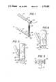
- FIG. 3is a fragmentary elevational view from the proximal end of the tube of a subglottiscope assembly comprising a first tube connected to the handle;
- FIG. 4is a vertical section taken on plane 4--4 of FIG. 3, showing the latch by which the tube is attached to the handle;
- FIG. 5is a vertical section taken on plane 5--5 of FIG. 1, showing how the two parts of the handle are attached together;
- FIG. 6is a fragmentary elevational view corresponding to FIG. 3, but showing a smaller subglottiscope tube attached to the same handle.
- the inventionis a subglottiscope set comprising a handle, a light carrier, and a plurality of subglottiscope tubes any one of which can be used with the handle and light carrier to provide a complete subglottiscope.
- a subglottiscope in accordance with the invention and as shown in FIG. 1,has three parts, a subglottiscope tube 8, and a handle comprising a first section 10, and a second section 12.
- the first section of the handleextends substantially perpendicular to the tube from a point near the proximal end 14 of the tube.
- the second section 12 of the handleis connected to the opposite end of section 10, and extends in the direction of, and parallel to tube 8.
- Tube 8is tapered, the proximal end 14 being somewhat larger in size than the distal end 16.
- the tubeis approximately 12 centimeters in length.
- the opening of the distal endis substantially circular, and has an internal diameter of less than approximately 8 millimeters.
- the opening at the proximal end 14is oval in shape, and has a maximum internal dimension between approximately 9.9 and 11.1 millimeters, and a minimum internal dimension between approximately 7.5 and 9.9 millimeters.
- a passage 18is formed along the wall of tube 16, and extends from an entrance opening 20 adjacent to proximal end 14 of the tube, to an exit opening (not shown in FIG. 1) adjacent to distal end 16 of the tube.
- the entrance openingis located immediately adjacent to the outer wall of tube 16, and passage 18 extends through the wall so that its exit opening is located immediately adjacent to the inner wall of tube 16.
- Passage 18receives a substantially rigid metal-clad fiberoptic light carrier 22, which has a coupling 24 adapted to be removably connected to a flexible light conductor. As shown in FIG. 1, coupling 24 extends approximately perpendicular to the direction of elongation of passage 18. Consequently, the flexible light conductor connected to coupling 24 does not interfere with the physician's attempt to look through tube 8.
- Handle section 12is clamped onto handle section 10 by means of a clamping screw 26, also shown in FIG. 5.
- Handle section 12has a hexagonal cross-section, adapted to be received in the clamp of a first type of subglottiscope support.
- the end of handle section 12 remote from screw 26has a threaded opening (not shown), which is adapted to receive the attachment screw of an alternative type of subglottiscope support known as a "Boston suspension".
- light carrier 22has a straight portion 28 adapted to enter opening 20 of passage 18 and to extend through passage 18 to a location near the distal end of tube 8.
- Light carrier 22has a curved section 30 which connects straight section 28 with coupling 24.
- a locating pin 32extends from coupling 24 in a direction parallel to straight section 28 of the light carrier. This pin is adapted to enter hole 34 in ear 36 of handle section 10.
- the cross-sections of straight portion 28 of the light carrierare circular as is the interior wall of passage 20.
- the engagement of pin 32 in hole 34prevents the light carrier from rotating in passage 18 as a result of forces applied to coupling 24 by the light-conducting cable to which coupling 24 is connected.
- the engagement of pin 32 in hole 34greatly reduces the tendency of the light carrier to move.
- tube 8has a locating pin 38 extending perpendicularly outwardly from its wall near the proximal end 14 of the tube. Adjacent to pin 38 is a latching pin 40, which also extends outwardly perpendicularly from wall 14. Latching pin 40 has a notch 42, which, as shown in FIG. 4, cooperates with a detent 44 of lever 46, which is pivoted on pin 48 and urged by compressed coil spring 50 so that detent 44 enters notch 42. On the side of pivot pin 48 remote from detent 44, lever 46 has a button 52 which, when depressed, causes detent 44 to disengage notch 42, allowing tube 8 to be detached from handle section 10.
- Pin 40is tapered at 54 so that, when pin 40 is inserted into hole 56 in the end of handle section 10, lever 46 is rotated so that detent 44 rides over surface 54 and drops into notch 42 whereby the tube and handle are automatically locked together.
- the tube and handletherefore snap together, and can easily be separated from each other by depressing pushbutton 52 and pulling them apart.
- the light carrierWhen the tube and handle are attached, the light carrier can be inserted into passage 18. When the light carrier is almost fully inserted, pin 32 enters hole 34 on handle 10.
- tube 8is attached to handle section 10, and light carrier 22 is inserted into passage 18, and has its pin 32 (not shown in FIG. 3) inserted into the hole in ear 36 of the handle.
- the position of the entrance opening 20 of passage 18 on the wall of tube 8is such that the distance between entrance opening 20 and the hole in ear 36 is equal to the distance between the straight portion 28 and pin 32 of the light carrier.
- FIG. 6in which a smaller laryngoscope tube 58 is connected to handle section 10.
- Entrance opening 60 of its light carrier passage 62is positioned on the wall of tube 58 so that when tube 58 is connected to handle section 10, the distance between entrance opening 60 and the hole in ear 36 is equal to the distance between the straight portion and pin 32 of the light carrier.
- the axis of the light carrier passageis the same distance from the wall of the subglottiscope tube in each case.
- the light carrieris rotated slightly counterclockwise in FIG. 6 as compared with its position in FIG. 3 because of the fact that the distance between entrance opening 60 and the central axis of tube 58 is slightly less than the distance between entrance opening 20 and the central axis of tube 8.
- the entrance openings of the light guide passagesare positioned on the peripheries of the walls of the tubes so that in each case, when the tube is attached to handle section 10, the distance between the entrance opening of its light carrier passage and the axis of the hole in ear 36 is the same.
- the same light guidecan be used with all of the tubes in the set.
- the subglottiscope set of the inventionis ideally suited for emergency treatment of newborns experiencing airway distress because it permits the physician to select a tube in the appropriate size, to insert it without the handle, thereby eliminating the possibility of exerting excess leverage through the handle during insertion and consequently reducing the likelihood of injury. Thereafter the physician may attach a first handle section for manipulation and a second separate handle section if a laryngoscope support is to be used.
- the positioning of the light carrier passage entrances on the tubesmakes it possible to use the same light carrier with all of the tubes in the set. It is unnecessary, in an emergency, to search among several light carriers of similar appearance to find the one corresponding to the particular subglottiscope tube selected for use.
- the laryngoscope setis, of course also well-suited for non-emergency diagnostic and surgical use.
Landscapes
- Health & Medical Sciences (AREA)
- Life Sciences & Earth Sciences (AREA)
- Surgery (AREA)
- Radiology & Medical Imaging (AREA)
- Engineering & Computer Science (AREA)
- Veterinary Medicine (AREA)
- Biophysics (AREA)
- Nuclear Medicine, Radiotherapy & Molecular Imaging (AREA)
- Optics & Photonics (AREA)
- Pathology (AREA)
- Public Health (AREA)
- General Health & Medical Sciences (AREA)
- Physics & Mathematics (AREA)
- Biomedical Technology (AREA)
- Heart & Thoracic Surgery (AREA)
- Medical Informatics (AREA)
- Molecular Biology (AREA)
- Animal Behavior & Ethology (AREA)
- Otolaryngology (AREA)
- Physiology (AREA)
- Pulmonology (AREA)
- Endoscopes (AREA)
Abstract
Description
Claims (7)
Priority Applications (1)
| Application Number | Priority Date | Filing Date | Title |
|---|---|---|---|
| US07/061,871US4799485A (en) | 1987-06-11 | 1987-06-11 | Neonatal subglottiscope set |
Applications Claiming Priority (1)
| Application Number | Priority Date | Filing Date | Title |
|---|---|---|---|
| US07/061,871US4799485A (en) | 1987-06-11 | 1987-06-11 | Neonatal subglottiscope set |
Publications (1)
| Publication Number | Publication Date |
|---|---|
| US4799485Atrue US4799485A (en) | 1989-01-24 |
Family
ID=22038681
Family Applications (1)
| Application Number | Title | Priority Date | Filing Date |
|---|---|---|---|
| US07/061,871Expired - LifetimeUS4799485A (en) | 1987-06-11 | 1987-06-11 | Neonatal subglottiscope set |
Country Status (1)
| Country | Link |
|---|---|
| US (1) | US4799485A (en) |
Cited By (17)
| Publication number | Priority date | Publication date | Assignee | Title |
|---|---|---|---|---|
| US4958624A (en)* | 1989-03-31 | 1990-09-25 | Welch Allyn, Inc. | Interchangeable laryngeal blade |
| WO1993020741A1 (en)* | 1992-04-08 | 1993-10-28 | Jako Geza J | Percutaneous surgical endoscopy |
| US5363840A (en)* | 1994-02-04 | 1994-11-15 | Silva Rafael E | Parallel laryngoscope with access opening |
| US5503617A (en)* | 1994-07-19 | 1996-04-02 | Jako; Geza J. | Retractor and method for direct access endoscopic surgery |
| GB2296436A (en)* | 1994-12-23 | 1996-07-03 | King Lewis Peter William | Light conducting blades for examination and intubation of body cavities |
| US5569108A (en)* | 1992-10-30 | 1996-10-29 | Gear Chain Industrial B.V. | Hybrid driving system |
| US5893830A (en)* | 1998-06-25 | 1999-04-13 | Zeitels; Steven | Universal modular laryngoscope/glottiscope system |
| US20050059857A1 (en)* | 2003-06-25 | 2005-03-17 | Richard Wolf Gmbh | Medical endoscope |
| US20060122580A1 (en)* | 2004-12-08 | 2006-06-08 | Patrick Dannan | Tool insertion device for use in minimally invasive surgery |
| US20060183978A1 (en)* | 2005-02-14 | 2006-08-17 | Howard Gregory L | Laryngoscope |
| US7338440B1 (en)* | 2004-12-02 | 2008-03-04 | Smith John D | Laryngoscope system with illuminator and suction capabilities |
| WO2009047603A3 (en)* | 2007-10-12 | 2009-10-22 | M.S. Vision Ltd | Intubation laryngoscope with a double holder |
| US20120029293A1 (en)* | 2010-07-30 | 2012-02-02 | Vasan Nilesh R | Disposable, Self-Contained Laryngoscope and Method of Using Same |
| US8337402B1 (en) | 2006-05-19 | 2012-12-25 | Ellis Charles W | Ambidextrous laryngoscope blade |
| US20140316206A1 (en)* | 2010-07-30 | 2014-10-23 | Nilesh R. Vasan | Disposable, self-contained laryngoscope and method of using same |
| US20170042415A1 (en)* | 2014-04-22 | 2017-02-16 | Srinivasa Murthy DORESWAMY | Pediatric laryngoscope, and method of use |
| USD876625S1 (en) | 2018-08-07 | 2020-02-25 | Adroit Surgical, Llc | Laryngoscope |
Citations (8)
| Publication number | Priority date | Publication date | Assignee | Title |
|---|---|---|---|---|
| GB375491A (en)* | 1931-05-09 | 1932-06-30 | Robert Schranz | Improvements in laryngoscopes and the like |
| GB612116A (en)* | 1944-11-30 | 1948-11-09 | Otto Popper | Improvements in specula |
| GB806467A (en)* | 1957-07-31 | 1958-12-23 | Walter Edward Wisbey | Improvements in bronchoscopes and like surgical instruments |
| US3592199A (en)* | 1970-02-09 | 1971-07-13 | Medical Products Corp | Autoclavable surgical instrument illumination |
| US4294235A (en)* | 1977-11-22 | 1981-10-13 | Karl Storz | Laryngoscope |
| US4406280A (en)* | 1981-10-16 | 1983-09-27 | Upsher Michael S | Laryngoscope including a disposable blade and its method of use |
| US4557256A (en)* | 1984-07-23 | 1985-12-10 | Jack Bauman | Examination device with an improved blade connection |
| US4567882A (en)* | 1982-12-06 | 1986-02-04 | Vanderbilt University | Method for locating the illuminated tip of an endotracheal tube |
- 1987
- 1987-06-11USUS07/061,871patent/US4799485A/ennot_activeExpired - Lifetime
Patent Citations (8)
| Publication number | Priority date | Publication date | Assignee | Title |
|---|---|---|---|---|
| GB375491A (en)* | 1931-05-09 | 1932-06-30 | Robert Schranz | Improvements in laryngoscopes and the like |
| GB612116A (en)* | 1944-11-30 | 1948-11-09 | Otto Popper | Improvements in specula |
| GB806467A (en)* | 1957-07-31 | 1958-12-23 | Walter Edward Wisbey | Improvements in bronchoscopes and like surgical instruments |
| US3592199A (en)* | 1970-02-09 | 1971-07-13 | Medical Products Corp | Autoclavable surgical instrument illumination |
| US4294235A (en)* | 1977-11-22 | 1981-10-13 | Karl Storz | Laryngoscope |
| US4406280A (en)* | 1981-10-16 | 1983-09-27 | Upsher Michael S | Laryngoscope including a disposable blade and its method of use |
| US4567882A (en)* | 1982-12-06 | 1986-02-04 | Vanderbilt University | Method for locating the illuminated tip of an endotracheal tube |
| US4557256A (en)* | 1984-07-23 | 1985-12-10 | Jack Bauman | Examination device with an improved blade connection |
Non-Patent Citations (8)
| Title |
|---|
| Drawings of Pending Design patent application 062,045, filed by Applicants on Jun. 11, 1987.* |
| Mueller Catalog; The Surgical Armamentarium; 1980; pp. 779, 782, 783, 836, 1214, 1215.* |
| Pilling Catalog "Laryngo-Bronchoesophagology", 1975, pp. 12-26B. |
| Pilling Catalog Laryngo Bronchoesophagology , 1975, pp. 12 26B.* |
| Pilling Catalog of "Cardiovascular, Thoracic and General Surgical Instruments", 1979, p. 301. |
| Pilling Catalog of Cardiovascular, Thoracic and General Surgical Instruments , 1979, p. 301.* |
| Woodrow, Jack H., "Improved Suspension Laryngoscope for Use With Operative Microscope", Transactions American Academy of Ophthalmology and Otolarynology, Mar.-Apr. 1971, p. 412. |
| Woodrow, Jack H., Improved Suspension Laryngoscope for Use With Operative Microscope , Transactions American Academy of Ophthalmology and Otolarynology, Mar. Apr. 1971, p. 412.* |
Cited By (25)
| Publication number | Priority date | Publication date | Assignee | Title |
|---|---|---|---|---|
| US4958624A (en)* | 1989-03-31 | 1990-09-25 | Welch Allyn, Inc. | Interchangeable laryngeal blade |
| WO1993020741A1 (en)* | 1992-04-08 | 1993-10-28 | Jako Geza J | Percutaneous surgical endoscopy |
| US5569108A (en)* | 1992-10-30 | 1996-10-29 | Gear Chain Industrial B.V. | Hybrid driving system |
| US5363840A (en)* | 1994-02-04 | 1994-11-15 | Silva Rafael E | Parallel laryngoscope with access opening |
| US5503617A (en)* | 1994-07-19 | 1996-04-02 | Jako; Geza J. | Retractor and method for direct access endoscopic surgery |
| GB2296436B (en)* | 1994-12-23 | 1998-12-02 | King Lewis Peter William | A Light Conducting Laryngoscope Blade |
| GB2296436A (en)* | 1994-12-23 | 1996-07-03 | King Lewis Peter William | Light conducting blades for examination and intubation of body cavities |
| US5893830A (en)* | 1998-06-25 | 1999-04-13 | Zeitels; Steven | Universal modular laryngoscope/glottiscope system |
| WO1999066826A1 (en)* | 1998-06-25 | 1999-12-29 | Steven Zeitels | Universal modular laryngoscope/glottiscope system |
| AU758382B2 (en)* | 1998-06-25 | 2003-03-20 | Steven Zeitels | Universal modular laryngoscope/glottiscope system |
| US20050059857A1 (en)* | 2003-06-25 | 2005-03-17 | Richard Wolf Gmbh | Medical endoscope |
| US7338440B1 (en)* | 2004-12-02 | 2008-03-04 | Smith John D | Laryngoscope system with illuminator and suction capabilities |
| US7559887B2 (en)* | 2004-12-08 | 2009-07-14 | Patrick Dannan | Tool insertion device for use in minimally invasive surgery |
| US20060122580A1 (en)* | 2004-12-08 | 2006-06-08 | Patrick Dannan | Tool insertion device for use in minimally invasive surgery |
| US20060183978A1 (en)* | 2005-02-14 | 2006-08-17 | Howard Gregory L | Laryngoscope |
| US8337402B1 (en) | 2006-05-19 | 2012-12-25 | Ellis Charles W | Ambidextrous laryngoscope blade |
| WO2009047603A3 (en)* | 2007-10-12 | 2009-10-22 | M.S. Vision Ltd | Intubation laryngoscope with a double holder |
| US20120029293A1 (en)* | 2010-07-30 | 2012-02-02 | Vasan Nilesh R | Disposable, Self-Contained Laryngoscope and Method of Using Same |
| US20140316206A1 (en)* | 2010-07-30 | 2014-10-23 | Nilesh R. Vasan | Disposable, self-contained laryngoscope and method of using same |
| US9289114B2 (en)* | 2010-07-30 | 2016-03-22 | Nilesh R. Vasan | Disposable, self-contained laryngoscope and method of using same |
| US9386915B2 (en)* | 2010-07-30 | 2016-07-12 | Nilesh R. Vasan | Disposable, self-contained laryngoscope and method of using same |
| US11478139B2 (en) | 2010-07-30 | 2022-10-25 | Adroit Surgical, Llc | Disposable, self-contained laryngoscope and method of using same |
| US20170042415A1 (en)* | 2014-04-22 | 2017-02-16 | Srinivasa Murthy DORESWAMY | Pediatric laryngoscope, and method of use |
| US10327628B2 (en)* | 2014-04-22 | 2019-06-25 | Srinivasa Murthy DORESWAMY | Pediatric laryngoscope, and method of use |
| USD876625S1 (en) | 2018-08-07 | 2020-02-25 | Adroit Surgical, Llc | Laryngoscope |
Similar Documents
| Publication | Publication Date | Title |
|---|---|---|
| US4799485A (en) | Neonatal subglottiscope set | |
| US20230210357A1 (en) | Disposable, self-contained laryngoscope and method of using same | |
| US4683879A (en) | Dual function connector for use with endotracheal apparatus | |
| US5261392A (en) | Laryngoscope with interchangeable fiberoptic assembly | |
| US6743166B2 (en) | Apparatus for introducing an intubation tube into the trachea | |
| US5941816A (en) | Viewing system with adapter handle for medical breathing tubes | |
| US5016614A (en) | Endotracheal intubation apparatus | |
| US5381787A (en) | Extendable and retractable laryngoscope | |
| US4050466A (en) | Endotracheal tube | |
| US5921917A (en) | Hand-held viewing system with removable sheath | |
| US5607386A (en) | Malleable fiberoptic intubating stylet and method | |
| EP0610206B1 (en) | Intubation device | |
| US4982729A (en) | Rigid fiberoptic intubating laryngoscope | |
| US6539942B2 (en) | Endotracheal intubation device | |
| CA2225669C (en) | Intubation system having an axially moveable memory cylinder | |
| US8677990B2 (en) | Endo-tracheal intubation device with adjustably bendable stylet | |
| US4949716A (en) | Nasal intubation adjunct | |
| US5890488A (en) | Coupling device and sound resonating membrane for a stethoscope and an endotracheal tube | |
| US7563227B2 (en) | Instrument for direct laryngoscopy with a rigid blade and flexible fiberoptics | |
| IL86626A (en) | Tracheostomy tube with ring pull removeble inner cannula | |
| JPH0622909A (en) | Laryngoscope with insertion stylet | |
| JPH05501660A (en) | Oral laryngeal and esophageal blind guidance and aiming device | |
| JP2021524359A (en) | Tracheal cannula insertion device | |
| US8667966B2 (en) | Intubating attachment and method | |
| US6090040A (en) | Periscope and retracting laryngoscope for intubation |
Legal Events
| Date | Code | Title | Description |
|---|---|---|---|
| AS | Assignment | Owner name:PILLING CO., 420 DELAWARE DRIVE, FORT WASHINGTON, Free format text:ASSIGNMENT OF ASSIGNORS INTEREST.;ASSIGNORS:FUREY, ANDREW J.;ROSENWALD, FREDERIC P.;REEL/FRAME:004743/0885 Effective date:19870609 Owner name:PILLING CO., PENNSYLVANIA Free format text:ASSIGNMENT OF ASSIGNORS INTEREST;ASSIGNORS:FUREY, ANDREW J.;ROSENWALD, FREDERIC P.;REEL/FRAME:004743/0885 Effective date:19870609 | |
| STCF | Information on status: patent grant | Free format text:PATENTED CASE | |
| FEPP | Fee payment procedure | Free format text:PAYOR NUMBER ASSIGNED (ORIGINAL EVENT CODE: ASPN); ENTITY STATUS OF PATENT OWNER: LARGE ENTITY | |
| FEPP | Fee payment procedure | Free format text:PAT HLDR NO LONGER CLAIMS SMALL ENT STAT AS SMALL BUSINESS (ORIGINAL EVENT CODE: LSM2); ENTITY STATUS OF PATENT OWNER: LARGE ENTITY | |
| FPAY | Fee payment | Year of fee payment:4 | |
| AS | Assignment | Owner name:TECHNOLOGY HOLDING COMPANY II, DELAWARE Free format text:ASSIGNMENT OF ASSIGNORS INTEREST;ASSIGNOR:PILLING WECK INCORPORATED;REEL/FRAME:007570/0834 Effective date:19941226 | |
| AS | Assignment | Owner name:PILLING WECK INCORPORATED, PENNSYLVANIA Free format text:CHANGE OF NAME;ASSIGNOR:PILLING CO.;REEL/FRAME:007786/0129 Effective date:19940520 | |
| FPAY | Fee payment | Year of fee payment:8 | |
| FPAY | Fee payment | Year of fee payment:12 |