US4798578A - Autotransfusion device - Google Patents
Autotransfusion deviceDownload PDFInfo
- Publication number
- US4798578A US4798578AUS07/014,508US1450887AUS4798578AUS 4798578 AUS4798578 AUS 4798578AUS 1450887 AUS1450887 AUS 1450887AUS 4798578 AUS4798578 AUS 4798578A
- Authority
- US
- United States
- Prior art keywords
- bag
- stiffener
- members
- slots
- inlet
- Prior art date
- Legal status (The legal status is an assumption and is not a legal conclusion. Google has not performed a legal analysis and makes no representation as to the accuracy of the status listed.)
- Expired - Lifetime
Links
- 210000001124body fluidAnatomy0.000claimsabstractdescription4
- 239000010839body fluidSubstances0.000claimsabstractdescription4
- 239000008280bloodSubstances0.000claimsdescription66
- 210000004369bloodAnatomy0.000claimsdescription66
- 239000003351stiffenerSubstances0.000claimsdescription46
- 239000012530fluidSubstances0.000claimsdescription10
- 239000000463materialSubstances0.000claimsdescription10
- 238000004891communicationMethods0.000claimsdescription9
- 238000001802infusionMethods0.000claimsdescription4
- 210000003739neckAnatomy0.000claims3
- 230000017531blood circulationEffects0.000claims1
- 239000007788liquidSubstances0.000abstractdescription9
- 229920003023plasticPolymers0.000description5
- XLYOFNOQVPJJNP-UHFFFAOYSA-NwaterSubstancesOXLYOFNOQVPJJNP-UHFFFAOYSA-N0.000description4
- 238000010276constructionMethods0.000description3
- 238000005187foamingMethods0.000description3
- 239000004033plasticSubstances0.000description3
- 239000007787solidSubstances0.000description3
- 239000002245particleSubstances0.000description2
- 230000002093peripheral effectEffects0.000description2
- 239000004800polyvinyl chlorideSubstances0.000description2
- 229920000915polyvinyl chloridePolymers0.000description2
- NIXOWILDQLNWCW-UHFFFAOYSA-Nacrylic acid groupChemical groupC(C=C)(=O)ONIXOWILDQLNWCW-UHFFFAOYSA-N0.000description1
- 239000000853adhesiveSubstances0.000description1
- 230000001070adhesive effectEffects0.000description1
- 239000003146anticoagulant agentSubstances0.000description1
- 229940127219anticoagulant drugDrugs0.000description1
- 230000000712assemblyEffects0.000description1
- 238000000429assemblyMethods0.000description1
- 230000005587bubblingEffects0.000description1
- 201000010099diseaseDiseases0.000description1
- 208000037265diseases, disorders, signs and symptomsDiseases0.000description1
- 230000000694effectsEffects0.000description1
- 238000001914filtrationMethods0.000description1
- 239000006260foamSubstances0.000description1
- 230000005484gravityEffects0.000description1
- 238000004519manufacturing processMethods0.000description1
- 239000002985plastic filmSubstances0.000description1
- 229920000515polycarbonatePolymers0.000description1
- 239000004417polycarbonateSubstances0.000description1
- 229920000728polyesterPolymers0.000description1
- 229920005644polyethylene terephthalate glycol copolymerPolymers0.000description1
- 238000011084recoveryMethods0.000description1
- 238000007789sealingMethods0.000description1
- 239000000126substanceSubstances0.000description1
- 238000001356surgical procedureMethods0.000description1
- 229920001169thermoplasticPolymers0.000description1
- 239000004416thermosoftening plasticSubstances0.000description1
- 238000011144upstream manufacturingMethods0.000description1
- 238000013022ventingMethods0.000description1
Images


Classifications
- A—HUMAN NECESSITIES
- A61—MEDICAL OR VETERINARY SCIENCE; HYGIENE
- A61M—DEVICES FOR INTRODUCING MEDIA INTO, OR ONTO, THE BODY; DEVICES FOR TRANSDUCING BODY MEDIA OR FOR TAKING MEDIA FROM THE BODY; DEVICES FOR PRODUCING OR ENDING SLEEP OR STUPOR
- A61M1/00—Suction or pumping devices for medical purposes; Devices for carrying-off, for treatment of, or for carrying-over, body-liquids; Drainage systems
- A61M1/60—Containers for suction drainage, adapted to be used with an external suction source
- A61M1/602—Mechanical means for preventing flexible containers from collapsing when vacuum is applied inside, e.g. stents
- A—HUMAN NECESSITIES
- A61—MEDICAL OR VETERINARY SCIENCE; HYGIENE
- A61M—DEVICES FOR INTRODUCING MEDIA INTO, OR ONTO, THE BODY; DEVICES FOR TRANSDUCING BODY MEDIA OR FOR TAKING MEDIA FROM THE BODY; DEVICES FOR PRODUCING OR ENDING SLEEP OR STUPOR
- A61M1/00—Suction or pumping devices for medical purposes; Devices for carrying-off, for treatment of, or for carrying-over, body-liquids; Drainage systems
- A61M1/02—Blood transfusion apparatus
Definitions
- This inventionrelates to autotransfusion devices and more particularly to autotransfusion devices subjected to negative pressures during blood collection.
- auxiliary autotransfusion blood collection containershave been employed with chest drainage units which permit reinfusion of the collected blood to the patient thereby avoiding the necessity of infusing stored blood from another person and the possibility of transmitting a disease to the patient.
- a blood collection bottle which is non-collapsiblehas been connected to a chest drainage unit such that suction is applied through the bottle to the plueral cavity of a patient with the bottle receiving drainage blood.
- the bottleIn order to reinfuse the blood into the patient, the bottle must be vented to atmosphere to allow the collected blood to flow from the bottle to the patient.
- airis in contact with the blood and may effect its characteristics.
- an air filtershould be used to filter air from the atmosphere into the container during infusion.
- Collapsible bag blood collection containershave also been used in order to avoid the necessity and problems of venting the container during reinfusion.
- collapsible bag-type containershave also had certain problems and disadvantages.
- the collapsible bagrequires apparatus to maintain the bag in an expanded condition during blood collection in spite of the negative pressures or suction forces within the bag. This has caused, in some cases, the bag and the bag expanding device to be complicated and expensive, and in general, such bags when expanded may take on indefinite shapes and produce indefinite volumes and produce inaccurate indications of the amount of blood collected at any time.
- known autotransufusion devicesemploy a filter placed in the patient drain line. This placement of the inlet filter creates several problems in use. In most cases during the initial stages of recovery from pneumo-thoracic surgery there is some leakgage of air at the wound site. The air passes with the blood, through the filter thus producing bubbling and foaming of blood. Such foaming gradually fills the air space in the device making it more difficult to determine the amount of blood collected at any given time and also creating a problem by expelling blood as well as air when the collection bag is squeezed to expell air prior to reinfusion of the patient's blood.
- an autotransfusion devicein accordance with one aspect of the present invention, includes a collapsible blood collection bag, and a pair of stiffening members connected to the opposed sides of the bag which are flexible in response to forces tending to move the opposed sides thereof toward each other to expand the bag for collecting blood.
- Each end of each of the stiffener membersis provided with a pair of slots extending from the opposed sides of the member inwardly at an angle to the longitudinal axis of the bag, the slots allowing the bag to form inclined surfaces at each of the opposite ends thereof when the bag is expanded for collecting blood.
- an autotransfusion blood collection and reinfusion devicewhich includes a blood collection chamber having an inlet for connection to a patient and a gas outlet for connection with a source of negative pressure during blood collection.
- a filter in the chamberis connected to filter blood flowing from the inlet to a blood collection portion of the chamber but gas can flow from the inlet to the gas outlet without flowing through the filter.
- an autotransfusion devicewhich includes a collapsible bag and stiffens for expanding the bag when forces are maintained on the stiffeners tending to move the opposed side edges toward each other, and a holder for receiving the bag and the stiffener members to maintain the bag in an expanded condition for receiving blood.
- the holderis generally cylindrical and has means for releasably connecting it to a chest drainage unit.
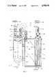
- FIG. 1is an elevational view, partly in section, of a chest drainage system including an autotransfusion device in accordance with a preferred embodiment of the present invention
- FIG. 2is a cross-sectional view taken along the line 2--2 of FIG. 1;
- FIG. 3is an enlarged side view of the bag assembly of FIG. 1 but in its unrestrained or free state condition;
- FIG. 4is an enlarged partial side view of the upper portion of the bag assembly of FIG. 3 with parts broken away;
- FIG. 5is an enlarged side elevational view of the autotransfusion device of FIG. 1 rotated 180° about the vertical axis with the holder of FIG. 1 broken away and parts removed;
- FIG. 6is a cross-sectional view taken along the line 6--6 of FIG. 5;
- FIG. 7is a cross-sectional view taken along the line 7--7 of FIG. 5;
- FIG. 8is a cross-sectional view taken along the line 8--8 of FIG. 4.
- FIG. 9is a plan view of the filter of FIG. 1 during a stange in the manufacture of the device of FIG. 1;
- FIG. 10is a top view of the holder of FIG. 1 when apart from the other apparatus of FIG. 1;
- FIG. 11is a cross-sectional elevational view of the holder of FIG. 10.
- a chest drainage system 10including an autotransfusion blood collection device 12 connected to the side of a chest drainage unit 14.
- the device 12includes an autotransfusion or blood collection or reinfusion bag assembly 16 and a bag expanding member or holder 18 receiving the bag assembly 18.
- Holder 18is releasably connected to the side of the chest drainage unit 14. As will be discussed hereafter, the holder 18 maintains the collapsible bag assembly 16 in an expanded condition for receiving body fluids from the plueral cavity of a patient indicated at 20.
- the collapsible blood collection and reinfusion bag assembly 16has an inlet 22 communicating with the interior of the bag assembly and shown connected to a tube 24.
- Tube 24is connected through a tube connector 26 to the proximal end of a patient tube 28 which is connected through a catheter to the plueral cavity of patient 20.
- Spaced from the inlet 22 at the top of the bag assembly 16is a gas outlet 30 communicating with the interior of the bag assembly and inlet 22.
- Gas outlet 30is connected to a tube 32 which, in turn, is connected to a tube 34 through a tube connector 36.
- Tube 34is connected to an inlet 38 of the cheest drainage unit 14.
- An auxiliary inlet 37 between the inlet and outlets 22 and 30communicates with the interior of the bag and is preferably a self-sealing seal which can be penetrated by a syringe needle for introducing a substance to the bag assembly 16, for example, an anticoagulant.
- Chest drainage unit 14is shown for illustration including a housing 39, preferably of rigid transparent plastic, for example, a polycarbonate or the like.
- the housing 39includes a fluid collection chamber 40, an underwater seal chamber indicated generally at 42, and a liquid manometer indicated at 44.
- the liquid underwater sealincludes a relatively narrow vertical channel 46 open at the top where it is in fluid communication with a collection chamber 40.
- Channel 46has an opening 48 at the bottom which communicates with a relatively large gas chamber 50 of the water seal 42 as seen in FIG. 2.
- a suction regulator 52Connected to the top of outlet chamber 50 is a suction regulator 52 that is connected by a flexible tube 54 to a source of suction 56 (FIG. 1) which sources may be a conventional hospital wall suction source.
- the liquid manometerincludes a vertical channel 58 connected in fluid communication with collection chamber 40 at the top and by a passage 60 at the bottom to a vertical column 62 that is open at the top to atmosphere. Both the underwater seal 42 and the liquid manometer 44 are shown provided with suitable quantities of a liquid such as water.
- the regulator 52regulates and limits the suction or negative pressure in the collection chamber 40 to a desired and safe value.
- the construction and operation of the chest drainage unit 14 including that of the suction regulator 52are shown described in detail in U.S. Pat. No. 4,372,336 and are hereby incorporated herein by reference.
- the collapsible blood collection and reinfusion bag assembly 16is shown in FIGS. 3 and 4 in its unrestrained or free condition, that is, without any compressive forces being applied to the assembly so that the assembly is in its substantially flat condition prior to being inserted into the holder 18.
- Assembly 16includes a collapsible pliable blood collection and reinfusion bag 64 formed of a pair of opposed sheet members or panels 66 and 68 sealed together about the periphery of the bag such as indicated by a peripheral seam 70 and which may be a heat seal.
- the pheripheral seal 70extends around the tubular inlet 22 and a gas outlet 30 to seal them at the top of the bag assembly in communication with the interior of the bag.
- the seal 70extends around seals a tubular blood outlet 72 at the bottom of the assembly.
- the blood outlet 72is closable by a plug 74 integrally tethered to the bag 64.
- the blood outlet 72is shown in FIG. 7 provided with a conventional piercable seal 75.
- Plug 74maintains the seal 75 clean.
- the panels 66 and 68 of bag assembly 16are preferably formed of pliable material such as a relatively soft polyvinyl chloride so that the bag is readily and easily collapsible.
- Bag assembly 16also includes a pair of flexible bag stiffener members 76 and 78 respectively fixed to the outer surfaces of front and back panels 66 and 68 of bag 64.
- Stiffener members of panels 76 and 78are in the form of generally flat sheet members of relatively stiff material, preferably, of a relatively rigid, resilient plastic sheet material such as polyester terephthaltate (PET-G) sheet material.
- PET-Gpolyester terephthaltate
- the stiffening members 76 and 78are identical in shape to each other in the illustrated embodiment, and only panel 76 is shown in its flattened condition as in FIG. 3. Also, in the illustrated embodiment, each of the stiffener panels 76 and 78 is symmetrical about the vertical or longitudinal axis 81 in FIG. 3. Panel 76 is provided with a pair of slots 80 and 82 which extend inwardly respectively from the opposed sides of the panel, indicated at 83 and 84, are are near, but spaced from, the upper edge 85 of the panel so that an upper portion 86 above the slots has a relatively narrow neck 87 integrally connecting the upper portion 86 to a relatively large main portion 88.
- the slots 80 and 82intersect the periphery of the stiffener member and have opposed pairs of opposed sidewalls 89 and 90, and 91 and 92, respectively, the slots narrowing toward the inner ends.
- the longitudinal axes of the slotsindicated at 93 and 94 in FIG. 3, cross approximately at the longitudinal axis 81 with the slot axes being at an angle of about 22° with respect to a lateral or horizontal line intersecting the axes.
- Panel 76also has a pair of slots 95 and 96 adjacent to but spaced from the bottom edge indicated at 97, and which extend respectively from the sidewalls 83 and 84 inwardly. Slots 95 and 96 also are widest at the periphery and have opposed sidewalls 98 and 99, and 100 and 101.
- the slots 95 and 96also have axes which intersect the vertical axis 80 and are at about 22° to a horizontal line.
- the inner ends of the slots 95 and 96are spaced from each other to provide a relatively narrow neck portion 102 that connects a lower portion 104 to the major central portion 88.
- the neck portions 87 and 102 between the inner ends of the two pairs of slotsare relatively narrow so that they are relatively flexible and readily bend to allow the upper, main and lower portions of each stiffener member to curve in different planes to form the expanded bag assembly 16 when when opposed compressive forces are applied to the opposed sides 83 and 84 of the assembly which applies the forces to the opposed side edges of the stiffener members 76 and 78.
- the bag assembly 16thus has an essentially cylindrical central portion, and inclined upper and lower portions when inserted into the holder 18, as seen in FIGS. 5, 6, 7.
- the back stiffener member 78is identical to stiffener member 76 as described above.
- the stiffener member 78is best seen in FIG. 5 and 6 where the bag assembly 16 is shown in its expanded condition in the holder 18.
- Member 78has an upper pair of slots 106 and 108 (identical to slots 80 and 82 in stiffener member 76) and a lower pair of slots 110 and 112 (identical to slots 95 and 96 in stiffener member 76).
- Stiffener member 78also has upper and lower narrow neck portions 114 and 116 between the inner portions 114 and 116 between the inner ends of the pairs of slots which connect the main portion 117 with upper and lower stiffener end portions 119 and 121 respectively.
- the two stiffener members 76 and 78are fixed to the bag 64 with the corresponding slots and portions of the two stiffener members in registration.
- a filter 120Connected within the upper portions of bag 64 is a filter 120, as best seen in FIGS. 4, 6, 8 and 9.
- the illustrated filter 120is shown including a fine plastic screen 122 in the form of a filter bag having a filter chamber 124 closed about its periphery with the inlet 22 and gas outlet 30 sealed to the filter and extending from the exterior of bag assembly 16 into the filter chamber 124.
- Filter 120may be formed by cutting suitable filtering screen material 122 into rectangular shape as shown in FIG. 9. Then a plastic frame formed from sheet material, such as a thermoplastic, for example, a polyvinyl chloride can be melt bonded to the periphery to form a border indicated at 126. Then the thus formed element can be folded in half, such as along the fold line 128, and the opposed sides 128 and 130 fused or melt bonded together and with the opposed ends 134 and 136 heat sealed together and about the inlet 22, outlet 30, and auxiliary inlet 37.
- sheet materialsuch as a thermoplastic, for example, a polyvinyl chloride
- the thus formed elementcan be folded in half, such as along the fold line 128, and the opposed sides 128 and 130 fused or melt bonded together and with the opposed ends 134 and 136 heat sealed together and about the inlet 22, outlet 30, and auxiliary inlet 37.
- FIG. 10shows a top view of the bag assembly 16 as viewed in FIG. 3.
- the slotsbeing wider at the mouth near the periphery of the bag assembly 16 permit the slots to close and allow the bag to readily assume the wedge shape at the top of the assembly and generally conical shape at the bottom of the assembly.
- the stiffener members 76 and 78are preferably connected substantially over their entire surfaces to the bag panels 66 and 68 respectively to cause the bag panels to bow outwardly with the stiffener members.
- the stiffener members and bag panelsare heat bonded or welded together over the entire meeting surfaces.
- a suitable adhesivecould be used in some cases.
- the bag assembly 16readily takes on the desired predetermined configuration and which will be maintained at the normal levels of suction used so that each bag manufactured will have substantially the same predetermined internal volume during operation of the chest drainage system and such assemblies can therefore be calibrated to provide relatively acurate indications of the volume of blood collected at any time.
- Calibrationare shown at 150 on the holder 18 in FIG. 1 and may include graduations in centiliters.
- the holder 18, as shown also in FIGS. 10 and 11,includes a substantially rigid cylindrical member or housing 142 having suitable lugs 143 and 144 integrally connected thereto for supporting engagement with suitable receptors 145 and 146 mounted onto one side of the chest drainage unit 14 as shown in FIG. 1.
- a releasable spring latch(not shown) may be provided on the holder 18 such as between the lugs and a cooperating latch pin (not shown) on the side of chest drainage unit 14.
- a latch and pinwould ensure that the autotransfusion device 12 and unit 14 would remain together during use and facilitate easy removal of the autotransfusion unit from the chest drainage unit and replacement.
- the holder 18has a cylindrical inner wall 151 providing a cylindrical chamber 152 for receiving and maintaining the bag assembly 16 in a generally cylindrical shape. That is, the opposed sides of the chamber or diameter in the illustrated embodiment are sized relative to the width of the bag assembly 16 such that the chember walls 151 continuously exert the necessary opposed compressive forces on the opposed side edges of the stiffener members adjacent the opposed sides 83 and 84 (FIG. 3). of the bag assembly 16 to maintain the bag assembly in an expanded condition as shown.
- a generally elliptical and inclined surface indicated a 160 in FIGS. 10 and 11which supports the generally conical bottom end of the bag assembly 16 to properly locate it within the holder, the bottom of the bag assembly being generally conical and somewhat elliptical at the bottom. The bottom of the assembly 16 rests on the surface 160.
- Filter 120catches solid or semi-solid particles within the filter bag allowing filtered blood to flow into the main collection portion 105 of the expanded bag assembly 16 so that such particles when the collected blood is subsequently reinfused into the patient do not enter and cause blockage of the fine filter conventionally used in the infusion line.
- the filteris connected about the inlet 22 and gas outlet 30 so that both of them communicate with the interior of the filter and are in direct fluid communication with each other. Since air or gas from the inlet 22 can pass directly to outlet 30, that is, without passing through filter screen 122, the suction or negative pressure does not cause blood within the filter to mix with air and cause foaming. That is, blood is not churned by the suction force tending to produce air bubble or foam.
- This configurationalso provides a safeguard in that, should the filter become blocked to the point that blood can no longer pass through it, any further blood emanating from the patient will since continue to flow out through the outlet tube 30 and into the collection chamber 40 of the chest drainage unit 14, thus protecting the patient by maintaining normal suctioning.
- tube clamps indicated at 154 and 156 and a patient tube clamp 160which are open during blood collection, are actuated to close tubes 24 and 28 and 32. Then the patient tube 28 and tube 34 may be disconnected from the tube connectors 26 and 36 so as to free the autotransfusion device 12 from the chest drainage unit 14. Tubes 28 and 34 are then connected together and the patient tube clamp 160 released so that patient chest drainage suction is maintained. Next, the blood collection and reinfusion bag assemby 16 can be slid upwardly and out of holder 18 and connected to a suitable frame or the like near the patient such as by using a hanger strap that may be provided at the top of the unit (not shown).
- cap 74 at the bottom of the bag assemblycan be removed from the blood outlet 72 whereupon a conventional spike can be inserted through the piercable seal 75 closing the outlet 72, the spike being connected to an infusion tube or catheter via a filter and drip chamber to infuse the patient's blood from the bag back into the same patient.
- the assembly 12may be disconnected from the chest drainage unit 14, discarded and replaced by a new bag and holder assembly 12.
- the patient tube 28is connected to the new tube 24 by connector 26 to connect the new bag assembly inlet 22 with patient tube 28.
- Tube 34is then connected to the new bag assembly outlet tube 32 and 30. Functioning is resumed by releasing patient tube clamp 160.
- the stiffener members 76 and 78 of bag assembly 16when the assembly is in a holder 18, provide the blood collection container bag or predetermined volume similar to a container having rigid sidewalls.
- the blood collection bag assembly 16since the blood collection bag assembly 16 is also collapsible, it can be used similar to a conventional collapsible blood collection bag.
- a conventional well-known blood bag pressurizing sleevecan be used to squeeze the assembly 16 to thereby infuse blood at a rate faster than that accomplished by use of gravity only.
- the autotransfusion device 12is assembled at the factory so that the bag assemby 16 is in the expanded condition in the holder 18 with sterile air in the bag 64.
- the bag assembly 16could be supplied in flattened or collasped condition if a vent with an air filter is employed.
- the holder 18 and chest drainage device housingmay be formed of acrylic material as wll as other relatively rigid plastics.
- the stiffener, holder, bag and chest drainage unitare formed of transparent plastic so that blood can be seen and monitored during operation of the system.
Landscapes
- Health & Medical Sciences (AREA)
- Vascular Medicine (AREA)
- Heart & Thoracic Surgery (AREA)
- Public Health (AREA)
- Anesthesiology (AREA)
- Biomedical Technology (AREA)
- Hematology (AREA)
- Life Sciences & Earth Sciences (AREA)
- Animal Behavior & Ethology (AREA)
- General Health & Medical Sciences (AREA)
- Engineering & Computer Science (AREA)
- Veterinary Medicine (AREA)
- External Artificial Organs (AREA)
- Lining Or Joining Of Plastics Or The Like (AREA)
- Pressure Welding/Diffusion-Bonding (AREA)
- Protection Of Pipes Against Damage, Friction, And Corrosion (AREA)
- Branch Pipes, Bends, And The Like (AREA)
- Medical Preparation Storing Or Oral Administration Devices (AREA)
- Extraction Or Liquid Replacement (AREA)
- Power Steering Mechanism (AREA)
- Catching Or Destruction (AREA)
- Sampling And Sample Adjustment (AREA)
Abstract
Description
This invention relates to autotransfusion devices and more particularly to autotransfusion devices subjected to negative pressures during blood collection.
More recently, auxiliary autotransfusion blood collection containers have been employed with chest drainage units which permit reinfusion of the collected blood to the patient thereby avoiding the necessity of infusing stored blood from another person and the possibility of transmitting a disease to the patient.
Some autotransfusion devices of this type have had certain problems or disadvantages associated with them. A blood collection bottle which is non-collapsible has been connected to a chest drainage unit such that suction is applied through the bottle to the plueral cavity of a patient with the bottle receiving drainage blood. In order to reinfuse the blood into the patient, the bottle must be vented to atmosphere to allow the collected blood to flow from the bottle to the patient. In such a case, air is in contact with the blood and may effect its characteristics. Also, an air filter should be used to filter air from the atmosphere into the container during infusion.
Collapsible bag blood collection containers have also been used in order to avoid the necessity and problems of venting the container during reinfusion. However, such collapsible bag-type containers have also had certain problems and disadvantages. For example, the collapsible bag requires apparatus to maintain the bag in an expanded condition during blood collection in spite of the negative pressures or suction forces within the bag. This has caused, in some cases, the bag and the bag expanding device to be complicated and expensive, and in general, such bags when expanded may take on indefinite shapes and produce indefinite volumes and produce inaccurate indications of the amount of blood collected at any time.
Because drainage fluids from the plueral cavity contain solids or semisolids, known autotransufusion devices employ a filter placed in the patient drain line. This placement of the inlet filter creates several problems in use. In most cases during the initial stages of recovery from pneumo-thoracic surgery there is some leakgage of air at the wound site. The air passes with the blood, through the filter thus producing bubbling and foaming of blood. Such foaming gradually fills the air space in the device making it more difficult to determine the amount of blood collected at any given time and also creating a problem by expelling blood as well as air when the collection bag is squeezed to expell air prior to reinfusion of the patient's blood.
It is therefore an object of the present invention to provide an improved blood collection and reinfusion device which is collapsible and which can be maintained in a predetermined expanded condition during blood collection and wherein the above-mentioned problems are substantially obviated. Another object is to provide an improved autotransfusion blood collection device which is expandable for collecting blood with suction applied thereto while maintaining a predetermined expanded condition and which is collapsible for reinfusion purposes. Still another object is to provide an improved autotransfusion device adapted for connection with a chest drainage unit which substantially avoids the above-mentioned disadvantages associated with collapsible bag autotransfusion devices.
In accordance with one aspect of the present invention, an autotransfusion device is provided with includes a collapsible blood collection bag, and a pair of stiffening members connected to the opposed sides of the bag which are flexible in response to forces tending to move the opposed sides thereof toward each other to expand the bag for collecting blood. Each end of each of the stiffener members is provided with a pair of slots extending from the opposed sides of the member inwardly at an angle to the longitudinal axis of the bag, the slots allowing the bag to form inclined surfaces at each of the opposite ends thereof when the bag is expanded for collecting blood.
In accordance with another aspect of the present invention, an autotransfusion blood collection and reinfusion device is provided which includes a blood collection chamber having an inlet for connection to a patient and a gas outlet for connection with a source of negative pressure during blood collection. A filter in the chamber is connected to filter blood flowing from the inlet to a blood collection portion of the chamber but gas can flow from the inlet to the gas outlet without flowing through the filter.
In accordance with still another aspect of the present invention, an autotransfusion device is provided which includes a collapsible bag and stiffens for expanding the bag when forces are maintained on the stiffeners tending to move the opposed side edges toward each other, and a holder for receiving the bag and the stiffener members to maintain the bag in an expanded condition for receiving blood. The holder is generally cylindrical and has means for releasably connecting it to a chest drainage unit.
These as well as other objects and advantages of the present invention will become apparent from the following detailed description and accompanying drawings.
FIG. 1 is an elevational view, partly in section, of a chest drainage system including an autotransfusion device in accordance with a preferred embodiment of the present invention;
FIG. 2 is a cross-sectional view taken along theline 2--2 of FIG. 1;
FIG. 3 is an enlarged side view of the bag assembly of FIG. 1 but in its unrestrained or free state condition;
FIG. 4 is an enlarged partial side view of the upper portion of the bag assembly of FIG. 3 with parts broken away;
FIG. 5 is an enlarged side elevational view of the autotransfusion device of FIG. 1 rotated 180° about the vertical axis with the holder of FIG. 1 broken away and parts removed;
FIG. 6 is a cross-sectional view taken along theline 6--6 of FIG. 5;
FIG. 7 is a cross-sectional view taken along theline 7--7 of FIG. 5;
FIG. 8 is a cross-sectional view taken along theline 8--8 of FIG. 4.
FIG. 9 is a plan view of the filter of FIG. 1 during a stange in the manufacture of the device of FIG. 1;
FIG. 10 is a top view of the holder of FIG. 1 when apart from the other apparatus of FIG. 1; and
FIG. 11 is a cross-sectional elevational view of the holder of FIG. 10.
Referring now to the drawings and particularly FIG. 1, achest drainage system 10 is shown including an autotransfusionblood collection device 12 connected to the side of achest drainage unit 14. Thedevice 12 includes an autotransfusion or blood collection orreinfusion bag assembly 16 and a bag expanding member orholder 18 receiving thebag assembly 18.Holder 18 is releasably connected to the side of thechest drainage unit 14. As will be discussed hereafter, theholder 18 maintains thecollapsible bag assembly 16 in an expanded condition for receiving body fluids from the plueral cavity of a patient indicated at 20.
The collapsible blood collection andreinfusion bag assembly 16 has aninlet 22 communicating with the interior of the bag assembly and shown connected to atube 24. Tube 24 is connected through atube connector 26 to the proximal end of apatient tube 28 which is connected through a catheter to the plueral cavity ofpatient 20. Spaced from theinlet 22 at the top of thebag assembly 16 is agas outlet 30 communicating with the interior of the bag assembly andinlet 22.Gas outlet 30 is connected to atube 32 which, in turn, is connected to atube 34 through atube connector 36. Tube 34 is connected to aninlet 38 of thecheest drainage unit 14. Anauxiliary inlet 37 between the inlet andoutlets bag assembly 16, for example, an anticoagulant.
When thechest drainage system 10 is operating, a partial vacuum or negative pressure exists in the underwater seal chamber 50 (FIG. 2), and any air or gas from the patient flows fromtube 28 into the upper portion ofbag assembly 16 throughinlet 22, then, intooutlet 30, intocollection chamber 40, downwardly through the water inunderwater seal channel 46, through the bottom opening 48, upwardly through the water in outlet chamber 50 (FIG. 2) and then to thesuction source 56. Theunderwater seal 42 prevents any atmospheric air from flowing through the unit to the patient. Because the liquid manometer is responsive to the pressure incollection chamber 40, the level of the liquid in theliquid manometer 44 will vary in height in accordance with negative pressure changes in the collection chamber, thus providing an indication of the suction level or negative pressure in the collection chamber and therefore in the plueral cavity of the patient. Theregulator 52 regulates and limits the suction or negative pressure in thecollection chamber 40 to a desired and safe value. The construction and operation of thechest drainage unit 14 including that of thesuction regulator 52 are shown described in detail in U.S. Pat. No. 4,372,336 and are hereby incorporated herein by reference.
The collapsible blood collection andreinfusion bag assembly 16 is shown in FIGS. 3 and 4 in its unrestrained or free condition, that is, without any compressive forces being applied to the assembly so that the assembly is in its substantially flat condition prior to being inserted into theholder 18.Assembly 16 includes a collapsible pliable blood collection andreinfusion bag 64 formed of a pair of opposed sheet members orpanels peripheral seam 70 and which may be a heat seal. Thepheripheral seal 70 extends around thetubular inlet 22 and agas outlet 30 to seal them at the top of the bag assembly in communication with the interior of the bag. Also, theseal 70 extends around seals atubular blood outlet 72 at the bottom of the assembly. Theblood outlet 72 is closable by aplug 74 integrally tethered to thebag 64. Theblood outlet 72 is shown in FIG. 7 provided with aconventional piercable seal 75.Plug 74 maintains theseal 75 clean. Thepanels bag assembly 16 are preferably formed of pliable material such as a relatively soft polyvinyl chloride so that the bag is readily and easily collapsible.
Preferably, the stiffeningmembers only panel 76 is shown in its flattened condition as in FIG. 3. Also, in the illustrated embodiment, each of thestiffener panels Panel 76 is provided with a pair ofslots upper edge 85 of the panel so that anupper portion 86 above the slots has a relativelynarrow neck 87 integrally connecting theupper portion 86 to a relatively largemain portion 88. Theslots opposed sidewalls Panel 76 also has a pair ofslots sidewalls Slots sidewalls slots vertical axis 80 and are at about 22° to a horizontal line. The inner ends of theslots narrow neck portion 102 that connects alower portion 104 to the majorcentral portion 88. Theneck portions bag assembly 16 when when opposed compressive forces are applied to the opposed sides 83 and 84 of the assembly which applies the forces to the opposed side edges of thestiffener members bag assembly 16 thus has an essentially cylindrical central portion, and inclined upper and lower portions when inserted into theholder 18, as seen in FIGS. 5, 6, 7.
Theback stiffener member 78 is identical tostiffener member 76 as described above. Thestiffener member 78, is best seen in FIG. 5 and 6 where thebag assembly 16 is shown in its expanded condition in theholder 18.Member 78 has an upper pair ofslots 106 and 108 (identical toslots slots 110 and 112 (identical toslots Stiffener member 78 also has upper and lowernarrow neck portions inner portions main portion 117 with upper and lowerstiffener end portions stiffener members bag 64 with the corresponding slots and portions of the two stiffener members in registration.
Connected within the upper portions ofbag 64 is afilter 120, as best seen in FIGS. 4, 6, 8 and 9. The illustratedfilter 120 is shown including afine plastic screen 122 in the form of a filter bag having afilter chamber 124 closed about its periphery with theinlet 22 andgas outlet 30 sealed to the filter and extending from the exterior ofbag assembly 16 into thefilter chamber 124.
After thecollection bag panels stiffener members peripheral seal 70 is formed in order to seal the peripheries ofpanels filter 120, including theends 134 and 136 (FIG. 9), sealed to and between thepanels top end 85 of thebag assembly 16. The upper end of thefilter 120 is preferably sandwiched between thepanels panels bag assembly 16 as viewed in FIG. 3.
When opposed compressive forces are applied to the opposedlateral sides arrows 140 and 141, the central portions ofstiffener members stiffener members assembly 16 is inserted into thetubular holder 18, the bag is expanded as indicated in FIGS. 1, 5, 6 and 7. As the opposed side edges 80 and 84 ofassembly 16, including the adjacent side edges of thestiffener members slots
The slots being wider at the mouth near the periphery of thebag assembly 16 permit the slots to close and allow the bag to readily assume the wedge shape at the top of the assembly and generally conical shape at the bottom of the assembly. The relativelynarrow neck portions stiffener member 76 andneck portions panel 78 readily bend to allow the upper and lower portions of theassemby 16 to readily become inclined when the bag is expanded into a generally cylindrical shape. Thestiffener members bag panels
With this construction, thebag assembly 16 readily takes on the desired predetermined configuration and which will be maintained at the normal levels of suction used so that each bag manufactured will have substantially the same predetermined internal volume during operation of the chest drainage system and such assemblies can therefore be calibrated to provide relatively acurate indications of the volume of blood collected at any time. Calibration are shown at 150 on theholder 18 in FIG. 1 and may include graduations in centiliters.
Theholder 18, as shown also in FIGS. 10 and 11, includes a substantially rigid cylindrical member orhousing 142 havingsuitable lugs suitable receptors chest drainage unit 14 as shown in FIG. 1. Where desired, a releasable spring latch (not shown) may be provided on theholder 18 such as between the lugs and a cooperating latch pin (not shown) on the side ofchest drainage unit 14. Such a latch and pin would ensure that theautotransfusion device 12 andunit 14 would remain together during use and facilitate easy removal of the autotransfusion unit from the chest drainage unit and replacement.
Theholder 18 has a cylindricalinner wall 151 providing acylindrical chamber 152 for receiving and maintaining thebag assembly 16 in a generally cylindrical shape. That is, the opposed sides of the chamber or diameter in the illustrated embodiment are sized relative to the width of thebag assembly 16 such that thechember walls 151 continuously exert the necessary opposed compressive forces on the opposed side edges of the stiffener members adjacent the opposed sides 83 and 84 (FIG. 3). of thebag assembly 16 to maintain the bag assembly in an expanded condition as shown.
Near the bottom of theholder 18 is a generally elliptical and inclined surface indicated a 160 in FIGS. 10 and 11 which supports the generally conical bottom end of thebag assembly 16 to properly locate it within the holder, the bottom of the bag assembly being generally conical and somewhat elliptical at the bottom. The bottom of theassembly 16 rests on thesurface 160.
In operation, when thechest drainage system 10 is connected as shown, blood and gas flow from the plueral cavity ofpatient 20 through theinlet 22 into the interior offilter 120. Blood filters through the filter and flows downwradly into theblood collection chamber 105 of thebag 64 while gas and air from theinlet 22 flows under the force of suction to the interior or filter bag and then, without passing the filter, into thegas outlet 30. The gas flows fromoutlet 30 intotube 34 and thechamber 40 by way ofinlet 38 of thechest drainage unit 14. Filter 120 catches solid or semi-solid particles within the filter bag allowing filtered blood to flow into themain collection portion 105 of the expandedbag assembly 16 so that such particles when the collected blood is subsequently reinfused into the patient do not enter and cause blockage of the fine filter conventionally used in the infusion line. The filter is connected about theinlet 22 andgas outlet 30 so that both of them communicate with the interior of the filter and are in direct fluid communication with each other. Since air or gas from theinlet 22 can pass directly tooutlet 30, that is, without passing throughfilter screen 122, the suction or negative pressure does not cause blood within the filter to mix with air and cause foaming. That is, blood is not churned by the suction force tending to produce air bubble or foam.
This configuration also provides a safeguard in that, should the filter become blocked to the point that blood can no longer pass through it, any further blood emanating from the patient will since continue to flow out through theoutlet tube 30 and into thecollection chamber 40 of thechest drainage unit 14, thus protecting the patient by maintaining normal suctioning.
Furthermore, should thebag 64 become over filled with blood, blood could overlfow throughtube 30 and into thecollection chamber 40. It is preferable to remove theautotransfusion device 12 from thechest drainage unit 14 when the blood collected in thebag 64 reaches a predetermined desired amount or, as would normally be the case, after a predetermined length of time.
When it is desired to infuse the patient with his own blood, tube clamps indicated at 154 and 156 and apatient tube clamp 160, which are open during blood collection, are actuated to closetubes patient tube 28 andtube 34 may be disconnected from thetube connectors autotransfusion device 12 from thechest drainage unit 14.Tubes patient tube clamp 160 released so that patient chest drainage suction is maintained. Next, the blood collection andreinfusion bag assemby 16 can be slid upwardly and out ofholder 18 and connected to a suitable frame or the like near the patient such as by using a hanger strap that may be provided at the top of the unit (not shown). By momentarily releasingclamp 156 and gently squeezing thebag assembly 16, excess air can be eliminated from the bag. Next, cap 74 at the bottom of the bag assembly can be removed from theblood outlet 72 whereupon a conventional spike can be inserted through thepiercable seal 75 closing theoutlet 72, the spike being connected to an infusion tube or catheter via a filter and drip chamber to infuse the patient's blood from the bag back into the same patient.
Should it be deemed necessary to collect further blood for reinfusion to the patient, theassembly 12 may be disconnected from thechest drainage unit 14, discarded and replaced by a new bag andholder assembly 12. To connect anew assembly 12 after the previous one has been discarded, and with, thepatient tube clamp 160 closed, thepatient tube 28 is connected to thenew tube 24 byconnector 26 to connect the newbag assembly inlet 22 withpatient tube 28.Tube 34 is then connected to the new bagassembly outlet tube patient tube clamp 160.
Thestiffener members bag assembly 16, when the assembly is in aholder 18, provide the blood collection container bag or predetermined volume similar to a container having rigid sidewalls. At the same time, since the bloodcollection bag assembly 16 is also collapsible, it can be used similar to a conventional collapsible blood collection bag. Also, a conventional well-known blood bag pressurizing sleeve can be used to squeeze theassembly 16 to thereby infuse blood at a rate faster than that accomplished by use of gravity only.
Because there is direct fluid communication between theinlet 22 andoutlet 30, that is, communication independently of thefilter 120, the suction to the patient will be maintained even if thefilter 120 becomes clogged. In contrast, where a filter is placed in the patient drain line upstream of the collection container, as in prior drainage systems, should such a filter become clogged, the suction to thepatient would be reduced or cut-off and this would endanger the patient.
Preferably, theautotransfusion device 12 is assembled at the factory so that thebag assemby 16 is in the expanded condition in theholder 18 with sterile air in thebag 64. However, where desired, thebag assembly 16 could be supplied in flattened or collasped condition if a vent with an air filter is employed.
Theholder 18 and chest drainage device housing may be formed of acrylic material as wll as other relatively rigid plastics. Preferably, the stiffener, holder, bag and chest drainage unit are formed of transparent plastic so that blood can be seen and monitored during operation of the system.
As various changes could be made in the above construction and without departing from the scope of the invention, it is intended that all matter contained in the above description and drawings shall be interpreted as illustrative and not in a limiting sense.
Claims (18)
1. A body fluid collection device comprising a collapsible bag assembly including a bag having a pair of opposed sidewalls and an inlet in fluid communication with the interior of said bag for receiving body fluid, and a pair of relatively stiff flexible members respectively connected to said sidewalls, said members having portions between the opposed side edges thereof bendable outwardly in opposite directions from each other to expand said bag in response to the application of a force tending to move said opposed side edges generally toward each other, each of said members having a pair of slots adjacent each of the opposite ends thereof, each of said slots having spaced opposed sidewalls, each pair slots extending inwarding from the opposed side edges of the member adjacent each of the opposite ends thereof.
2. The device of claim 1 wherein said flexible members are respectively fixed to the outer surfaces of said sidewalls of the bag.
3. The device of claim 1 wherein the sidewalls of each of said slots converge at a point inwardly of the periphery of the member.
4. The device of claim 2 wherein the sidewalls of each of the slots are farthest apart at the periphery of the stiffener member.
5. The device of claim 4 wherein the inner ends of the slots of each pair of slots define a portion of the stiffener member of smaller width than portions of the stiffener member above and below the defined portion.
6. The device of claim 1 wherein, at each end of each of said stiffener members, each pair of slots defines a neck portion inwardly spaced from the end of the stiffener and a relatively wide portion between the neck portion and the end of stiffener member.
7. The device of claim 1 further includes a holder for maintaining a force on the opposed sides of said stiffener members to maintain the stiffener members bent outwardly and said bag expanded.
8. The device of claim 7 wherein said holder is a generally tubular member having an inner diameter less than the width of said stiffener members.
9. The device of claim 8 wherein said holder includes means for releasably connecting said holder to a chest drainage unit.
10. The device of claim 1 further includes a filter adjacent to the upper portion of said bag connected to filter blood from said inlet to the lower portion of said bag, and a gas outlet adjacent said inlet and in direct fluid communication with said inlet whereby gas can flow from said inlet without flowing through said filter.
11. The device of claim 1 wherein said inlet is connected at the upper end portion of said bag, and said bag further includes a gas outlet spaced from said inlet at the upper end portion of said bag.
12. The device of claim 1 wherein said flexible members are heat bonded to the outer surfaces of the opposed walls of said bag and substantially over the entire meeting surfaces of the walls and flexible members.
13. The device of claim 12 further including a tubular fluid outlet at the bottom of said bag whereby said bag assembly can be emptied therethrough.
14. The device of claim 1 including a cylindrical holder for maintaining opposed forces on the opposed side edges of said bag assembly to shape said bag assembly so tht it has a generally cylindrical shape in the main central portion thereof, a generally wedge shape at the top, and a generally concial shape at the bottom.
15. The device of claim 1 wherein each of said slots has a longitudinal axis at an angle of about 22° with respect to a line normal to the longitudinal axis of said bag.
16. An autotransfusion device comprising a collapsible blood collection and infusion bag having a pair of opposed pliable panels of sheet material sealed together, an inlet and a gas outlet connected at the upper end of the bag, a pair of resilient, flexible stiffener members of sheet material which is more rigid than said material of said panels connected to the outer surfaces of said panels in parallel relation with each other, each of said stiffener members having respectively at the upper and lower ends thereof a pair of slots with spaced sidewalls, the slots of each pair extending inwardly from the opposed sides of each of the stiffener member defining a tab portion at each of the upper and lower ends of each of the stiffener members connected respectively by relatively narrow flexbile necks to a central main portion of each of the stiffener members, and holder means for receiving said bag and said stiffener members sized to maintain a compressive force on said stiffener members to cause said stiffener members to be bowed outwardly from each other to cause said bag to be in expaned condition with each of said panels having different axes of symmetry for receiving blood, and means for connecting said gas outlet to a source of suction.
17. The device of claim 15 wherein said connecting means includes a chest drainage unit.
18. The device of claim 16 further including a filter connected within said bag in the upper portion thereof, said filter being connected to receive and pass blood flow from said inlet to the lower portions of said bag and said gas outlet being in direct fluid communication with said inlet in by-passing relation with said filter.
Priority Applications (10)
| Application Number | Priority Date | Filing Date | Title |
|---|---|---|---|
| US07/014,508US4798578A (en) | 1987-02-13 | 1987-02-13 | Autotransfusion device |
| EP88301176AEP0278770B1 (en) | 1987-02-13 | 1988-02-12 | Autotransfusion device |
| ES198888301176TES2039611T3 (en) | 1987-02-13 | 1988-02-12 | AUTOTRANSFUSION DEVICE. |
| DE8888301176TDE3880339T2 (en) | 1987-02-13 | 1988-02-12 | DEVICE FOR AUTOTRANSFUSION. |
| CA000558829ACA1302825C (en) | 1987-02-13 | 1988-02-12 | Auto transfusion device |
| AT88301176TATE88358T1 (en) | 1987-02-13 | 1988-02-12 | DEVICE FOR AUTOTRANSFUSION. |
| AU11661/88AAU604838B2 (en) | 1987-02-13 | 1988-02-12 | Auto transfusion device |
| JP63031700AJPH0667402B2 (en) | 1987-02-13 | 1988-02-13 | Automatic blood transfusion device |
| SG27394ASG27394G (en) | 1987-02-13 | 1994-02-21 | Autotransfusion device. |
| HK34894AHK34894A (en) | 1987-02-13 | 1994-04-14 | Autotransfusion device |
Applications Claiming Priority (1)
| Application Number | Priority Date | Filing Date | Title |
|---|---|---|---|
| US07/014,508US4798578A (en) | 1987-02-13 | 1987-02-13 | Autotransfusion device |
Publications (1)
| Publication Number | Publication Date |
|---|---|
| US4798578Atrue US4798578A (en) | 1989-01-17 |
Family
ID=21765905
Family Applications (1)
| Application Number | Title | Priority Date | Filing Date |
|---|---|---|---|
| US07/014,508Expired - LifetimeUS4798578A (en) | 1987-02-13 | 1987-02-13 | Autotransfusion device |
Country Status (9)
| Country | Link |
|---|---|
| US (1) | US4798578A (en) |
| EP (1) | EP0278770B1 (en) |
| JP (1) | JPH0667402B2 (en) |
| AT (1) | ATE88358T1 (en) |
| AU (1) | AU604838B2 (en) |
| CA (1) | CA1302825C (en) |
| DE (1) | DE3880339T2 (en) |
| ES (1) | ES2039611T3 (en) |
| HK (1) | HK34894A (en) |
Cited By (75)
| Publication number | Priority date | Publication date | Assignee | Title |
|---|---|---|---|---|
| US4857042A (en)* | 1988-03-16 | 1989-08-15 | Sherwood Medical Company | Body fluid collection device |
| US4959062A (en)* | 1989-02-23 | 1990-09-25 | C. R. Bard, Inc. | Integrated soft shell reservoir |
| US4976707A (en)* | 1988-05-04 | 1990-12-11 | Sherwood Medical Company | Fluid collection, storage and infusion apparatus |
| US5011470A (en)* | 1990-08-29 | 1991-04-30 | Bioresearch, Inc. | Combined surgical drainage and autotransfusion apparatus |
| WO1991013677A1 (en)* | 1990-03-07 | 1991-09-19 | Shettigar U Ramakrishna | Autologous blood recovery membrane system and method |
| USD322124S (en) | 1989-07-13 | 1991-12-03 | Gish Biomedical Inc. | Autotransfusion unit with vacuum regulation cardiotomy reservoir |
| US5149325A (en)* | 1991-02-25 | 1992-09-22 | Baxter International Inc. | Vacuum system for auto transfusion device |
| US5215519A (en)* | 1990-03-07 | 1993-06-01 | Shettigar U Ramakrishna | Autotransfusion membrane system with means for providing reverse filtration |
| US5223228A (en)* | 1991-02-25 | 1993-06-29 | Baxter International Inc. | Tray for autotransfusion module |
| USD337382S (en) | 1989-10-23 | 1993-07-13 | H. G. Wallace Limited | Drainage bag |
| USD339194S (en) | 1991-02-25 | 1993-09-07 | Baxter International Inc. | Pressure control module |
| US5318556A (en)* | 1993-04-09 | 1994-06-07 | Deknatel Technology Corporation | Fluid bag |
| US5372593A (en)* | 1986-02-18 | 1994-12-13 | Boehringer Laboratories | Process and apparatus for collecting blood of a patient for autotransfusion |
| US5374257A (en)* | 1992-03-23 | 1994-12-20 | C. R. Bard, Inc. | Fluid collection chamber |
| US5382244A (en)* | 1991-02-25 | 1995-01-17 | Baxter International Inc. | Stand alone control module |
| US5423781A (en)* | 1992-05-11 | 1995-06-13 | The Uab Research Foundation | Method and apparatus for measuring the volume of a fluid |
| US5571179A (en)* | 1994-03-31 | 1996-11-05 | Manders; Ernest C. | Dimensionally adjustable soft tissue expander and method |
| US5695489A (en)* | 1991-09-30 | 1997-12-09 | Baxter International Inc. | Blood filtering container |
| US5713879A (en)* | 1994-02-26 | 1998-02-03 | Metec A. Schneider Gmbh | Device for collecting and filtering blood |
| US5718687A (en)* | 1995-09-11 | 1998-02-17 | Deco Delta Gmbh | Extra-corporal blood pump |
| US5722964A (en)* | 1995-03-13 | 1998-03-03 | Atrium Medical Corporation | Filtered blood collection device |
| US5724988A (en)* | 1991-10-18 | 1998-03-10 | Baxter International Inc. | Bone marrow kit |
| US5863436A (en)* | 1990-05-24 | 1999-01-26 | Pall Corporation | Venting system |
| US5876611A (en)* | 1997-06-16 | 1999-03-02 | Shettigar; U. Ramakrishna | Intraoperative blood salvaging system and method |
| US5885261A (en)* | 1996-04-25 | 1999-03-23 | C. R. Bard, Inc. | Autotransfusion system and method |
| US5897534A (en)* | 1996-08-29 | 1999-04-27 | Team Medical, Llc | Body fluids and solids drainage system |
| US5925025A (en)* | 1996-06-05 | 1999-07-20 | Tyco Group S.A.R.L. | Filtration valve cap with reflux clearing feature and related method of use thereof |
| US5931821A (en)* | 1996-03-05 | 1999-08-03 | Tyco Group S.A.R.L. | Chest drainage unit with controlled automatic excess negativity relief feature |
| US6086770A (en)* | 1990-05-24 | 2000-07-11 | Pall Corporation | Venting system |
| US6099493A (en)* | 1997-05-06 | 2000-08-08 | Sherwood Services, Ag | Continuous autotransfusion filtration system |
| US6152902A (en)* | 1997-06-03 | 2000-11-28 | Ethicon, Inc. | Method and apparatus for collecting surgical fluids |
| US6189704B1 (en) | 1993-07-12 | 2001-02-20 | Baxter International Inc. | Inline filter |
| US6210391B1 (en) | 1998-11-19 | 2001-04-03 | Genzyme Corporation | Rapid transfer autotransfusion bag and methods related thereto |
| US6217544B1 (en) | 1997-05-30 | 2001-04-17 | Sherwood Services, Ag | Filtration valve cap with reflux clearing feature and related method of use thereof |
| US6319221B1 (en) | 1998-12-14 | 2001-11-20 | Ethicon, Inc. | System for fluid retention management |
| US6367634B1 (en) | 1993-12-22 | 2002-04-09 | Baxter International Inc. | Blood collection systems including an integral, flexible filter |
| US6391009B1 (en)* | 1999-01-18 | 2002-05-21 | CROSA DORADO VALENTíN LORENZO | Disposable pleural aspiration device |
| US6422397B1 (en) | 1993-12-22 | 2002-07-23 | Baxter International, Inc. | Blood collection systems including an integral, flexible filter |
| US20030079803A1 (en)* | 2001-11-01 | 2003-05-01 | Romano Jack W. | Sterile liquid materials distribution, consumption and material waste disposal method and apparatus |
| US6601710B2 (en) | 1999-04-20 | 2003-08-05 | Baxter International Inc. | Filter assembly having a flexible housing |
| US20030209479A1 (en)* | 2000-07-10 | 2003-11-13 | Lynn Daniel R | Blood filters, blood collection and processing systems, and methods therefore |
| KR100418597B1 (en)* | 2001-10-16 | 2004-02-14 | 아성프라스틱공업 주식회사 | Bag for containing medical solution |
| US20040243105A1 (en)* | 2001-06-06 | 2004-12-02 | Swan Julian Francis Ralph | Autologous blood recovery apparatus |
| US20050010153A1 (en)* | 2001-12-26 | 2005-01-13 | Lockwood Jeffrey S | Vaccum bandage packing |
| US20050090787A1 (en)* | 1999-11-29 | 2005-04-28 | Risk James R.Jr. | Wound treatment apparatus |
| US20060015087A1 (en)* | 2001-10-11 | 2006-01-19 | Risk James R Jr | Waste container for negative pressure therapy |
| US20060029650A1 (en)* | 2000-05-22 | 2006-02-09 | Coffey Arthur C | Combination SIS and vacuum bandage and method |
| US20060041247A1 (en)* | 2002-08-21 | 2006-02-23 | Robert Petrosenko | Wound packing for preventing wound closure |
| US20070020142A1 (en)* | 2005-04-21 | 2007-01-25 | Federspiel William J | Paracorporeal respiratory assist lung |
| US7207966B2 (en) | 1995-11-01 | 2007-04-24 | Ethicon, Inc. | System for fluid retention management |
| US20070244464A1 (en)* | 2006-04-12 | 2007-10-18 | Fangrow Thomas F | Vial adaptor for regulating pressure |
| US20070293806A1 (en)* | 2006-06-20 | 2007-12-20 | Eurosets S.R.L. | Venous bag in an extracorporeal blood circuit |
| US7338482B2 (en) | 2002-02-28 | 2008-03-04 | Hill-Rom Services, Inc. | External catheter access to vacuum bandage |
| US20080249498A1 (en)* | 2007-03-09 | 2008-10-09 | Icu Medical, Inc. | Vial adaptors and vials for regulating pressure |
| US20090292263A1 (en)* | 2008-05-21 | 2009-11-26 | Tyco Healthcare Group, Lp | Wound therapy system with portable container apparatus |
| US20100049157A1 (en)* | 2008-08-20 | 2010-02-25 | Fangrow Thomas F | Anti-reflux vial adaptors |
| US20100106117A1 (en)* | 2000-11-29 | 2010-04-29 | Kci Medical Resources | Vacuum therapy and cleansing dressing for wounds |
| US7723560B2 (en) | 2001-12-26 | 2010-05-25 | Lockwood Jeffrey S | Wound vacuum therapy dressing kit |
| US7763000B2 (en) | 1999-11-29 | 2010-07-27 | Risk Jr James R | Wound treatment apparatus having a display |
| US7794438B2 (en) | 1998-08-07 | 2010-09-14 | Alan Wayne Henley | Wound treatment apparatus |
| US7896864B2 (en) | 2001-12-26 | 2011-03-01 | Lockwood Jeffrey S | Vented vacuum bandage with irrigation for wound healing and method |
| US7988680B2 (en) | 2000-11-29 | 2011-08-02 | Kci Medical Resources | Vacuum therapy and cleansing dressing for wounds |
| US8168848B2 (en) | 2002-04-10 | 2012-05-01 | KCI Medical Resources, Inc. | Access openings in vacuum bandage |
| US20150129510A1 (en)* | 2009-04-16 | 2015-05-14 | Pecofacet (Oklahoma) Llc | Bagged filter cartridge, system and method |
| US9089475B2 (en) | 2013-01-23 | 2015-07-28 | Icu Medical, Inc. | Pressure-regulating vial adaptors |
| US9132062B2 (en) | 2011-08-18 | 2015-09-15 | Icu Medical, Inc. | Pressure-regulating vial adaptors |
| US9610217B2 (en) | 2012-03-22 | 2017-04-04 | Icu Medical, Inc. | Pressure-regulating vial adaptors |
| US9615997B2 (en) | 2013-01-23 | 2017-04-11 | Icu Medical, Inc. | Pressure-regulating vial adaptors |
| US9987195B2 (en) | 2012-01-13 | 2018-06-05 | Icu Medical, Inc. | Pressure-regulating vial adaptors and methods |
| US10201476B2 (en) | 2014-06-20 | 2019-02-12 | Icu Medical, Inc. | Pressure-regulating vial adaptors |
| US10292904B2 (en) | 2016-01-29 | 2019-05-21 | Icu Medical, Inc. | Pressure-regulating vial adaptors |
| US10406072B2 (en) | 2013-07-19 | 2019-09-10 | Icu Medical, Inc. | Pressure-regulating fluid transfer systems and methods |
| CN111741777A (en)* | 2018-02-22 | 2020-10-02 | 塞雷斯公司 | Collecting pad |
| US10912869B2 (en) | 2008-05-21 | 2021-02-09 | Smith & Nephew, Inc. | Wound therapy system with related methods therefor |
| US11744775B2 (en) | 2016-09-30 | 2023-09-05 | Icu Medical, Inc. | Pressure-regulating vial access devices and methods |
Families Citing this family (5)
| Publication number | Priority date | Publication date | Assignee | Title |
|---|---|---|---|---|
| CA1326417C (en)* | 1988-02-25 | 1994-01-25 | Leonard D. Kurtz | Liquid reinfusion bag system |
| US4955877A (en)* | 1989-10-06 | 1990-09-11 | Bioresearch, Inc. | Autotransfusion bag |
| US7824343B2 (en)* | 1999-07-29 | 2010-11-02 | Fenwal, Inc. | Method and apparatus for blood sampling |
| JP5199642B2 (en)* | 2007-10-22 | 2013-05-15 | 川澄化学工業株式会社 | Sampling bag and blood collection device |
| JP2015058212A (en)* | 2013-09-19 | 2015-03-30 | 泉工医科工業株式会社 | Sheet reservoir |
Citations (12)
| Publication number | Priority date | Publication date | Assignee | Title |
|---|---|---|---|---|
| FR1049763A (en)* | 1952-01-23 | 1953-12-31 | Special device for hypodermic and intramusoular injections by automatic spring pricks | |
| US3473532A (en)* | 1966-06-15 | 1969-10-21 | Melvin I Eisenberg | Fluid container bag with self-closing one-way valve |
| US3557786A (en)* | 1968-06-18 | 1971-01-26 | Abbott Lab | Administration apparatus for intravenous substances |
| US3734154A (en)* | 1971-04-23 | 1973-05-22 | Packaging Ass Inc | Disposable bag with self-closing valve |
| DE2330101A1 (en)* | 1973-06-13 | 1975-01-09 | Fresenius Chem Pharm Ind | Plasticiser-free plastic collapsible bag - formed with grooves in (one half of) the bag for flexibility |
| US4006745A (en)* | 1975-05-22 | 1977-02-08 | Sorenson Research Co., Inc. | Autologous transfusion system and method |
| US4105031A (en)* | 1975-10-10 | 1978-08-08 | Deknatel, Inc. | Attachable expansion chamber for pleural drainage device |
| US4161179A (en)* | 1977-08-08 | 1979-07-17 | Metatech Corporation | Vacuum bag for wound drainage |
| US4429693A (en)* | 1980-09-16 | 1984-02-07 | Blake L W | Surgical fluid evacuator |
| US4443220A (en)* | 1982-03-16 | 1984-04-17 | Hauer Jerome Maurice | Blood collection and transfer apparatus |
| US4540413A (en)* | 1983-06-17 | 1985-09-10 | Russo Ronald D | Cardiopulmonary drainage collector with blood transfer adapter |
| US4583972A (en)* | 1984-05-18 | 1986-04-22 | Complex, Inc. | Wound evacuator |
Family Cites Families (2)
| Publication number | Priority date | Publication date | Assignee | Title |
|---|---|---|---|---|
| FR2389383A1 (en)* | 1977-05-04 | 1978-12-01 | Johnson & Johnson | |
| FI854147L (en)* | 1984-11-23 | 1986-05-24 | Steridose Systems Ab | BEHAOLLARE. |
- 1987
- 1987-02-13USUS07/014,508patent/US4798578A/ennot_activeExpired - Lifetime
- 1988
- 1988-02-12ATAT88301176Tpatent/ATE88358T1/ennot_activeIP Right Cessation
- 1988-02-12ESES198888301176Tpatent/ES2039611T3/ennot_activeExpired - Lifetime
- 1988-02-12CACA000558829Apatent/CA1302825C/ennot_activeExpired - Lifetime
- 1988-02-12EPEP88301176Apatent/EP0278770B1/ennot_activeExpired - Lifetime
- 1988-02-12DEDE8888301176Tpatent/DE3880339T2/ennot_activeExpired - Lifetime
- 1988-02-12AUAU11661/88Apatent/AU604838B2/ennot_activeExpired
- 1988-02-13JPJP63031700Apatent/JPH0667402B2/ennot_activeExpired - Lifetime
- 1994
- 1994-04-14HKHK34894Apatent/HK34894A/ennot_activeIP Right Cessation
Patent Citations (12)
| Publication number | Priority date | Publication date | Assignee | Title |
|---|---|---|---|---|
| FR1049763A (en)* | 1952-01-23 | 1953-12-31 | Special device for hypodermic and intramusoular injections by automatic spring pricks | |
| US3473532A (en)* | 1966-06-15 | 1969-10-21 | Melvin I Eisenberg | Fluid container bag with self-closing one-way valve |
| US3557786A (en)* | 1968-06-18 | 1971-01-26 | Abbott Lab | Administration apparatus for intravenous substances |
| US3734154A (en)* | 1971-04-23 | 1973-05-22 | Packaging Ass Inc | Disposable bag with self-closing valve |
| DE2330101A1 (en)* | 1973-06-13 | 1975-01-09 | Fresenius Chem Pharm Ind | Plasticiser-free plastic collapsible bag - formed with grooves in (one half of) the bag for flexibility |
| US4006745A (en)* | 1975-05-22 | 1977-02-08 | Sorenson Research Co., Inc. | Autologous transfusion system and method |
| US4105031A (en)* | 1975-10-10 | 1978-08-08 | Deknatel, Inc. | Attachable expansion chamber for pleural drainage device |
| US4161179A (en)* | 1977-08-08 | 1979-07-17 | Metatech Corporation | Vacuum bag for wound drainage |
| US4429693A (en)* | 1980-09-16 | 1984-02-07 | Blake L W | Surgical fluid evacuator |
| US4443220A (en)* | 1982-03-16 | 1984-04-17 | Hauer Jerome Maurice | Blood collection and transfer apparatus |
| US4540413A (en)* | 1983-06-17 | 1985-09-10 | Russo Ronald D | Cardiopulmonary drainage collector with blood transfer adapter |
| US4583972A (en)* | 1984-05-18 | 1986-04-22 | Complex, Inc. | Wound evacuator |
Non-Patent Citations (2)
| Title |
|---|
| Deknatel, "Why transfuse if you can reinfuse with the Pleur-Evao® Autotransfusion System?", The Journal of Thoracic and Cardiovascular Surgery, vol. 93, No. 2, Feb. 1987. |
| Deknatel, Why transfuse if you can reinfuse with the Pleur Evao Autotransfusion System , The Journal of Thoracic and Cardiovascular Surgery, vol. 93, No. 2, Feb. 1987.* |
Cited By (175)
| Publication number | Priority date | Publication date | Assignee | Title |
|---|---|---|---|---|
| US5372593A (en)* | 1986-02-18 | 1994-12-13 | Boehringer Laboratories | Process and apparatus for collecting blood of a patient for autotransfusion |
| EP0333470A3 (en)* | 1988-03-16 | 1990-02-28 | Sherwood Medical Company | Body fluid collection device |
| US4857042A (en)* | 1988-03-16 | 1989-08-15 | Sherwood Medical Company | Body fluid collection device |
| US4976707A (en)* | 1988-05-04 | 1990-12-11 | Sherwood Medical Company | Fluid collection, storage and infusion apparatus |
| US4959062A (en)* | 1989-02-23 | 1990-09-25 | C. R. Bard, Inc. | Integrated soft shell reservoir |
| USD322124S (en) | 1989-07-13 | 1991-12-03 | Gish Biomedical Inc. | Autotransfusion unit with vacuum regulation cardiotomy reservoir |
| USD337382S (en) | 1989-10-23 | 1993-07-13 | H. G. Wallace Limited | Drainage bag |
| US5215519A (en)* | 1990-03-07 | 1993-06-01 | Shettigar U Ramakrishna | Autotransfusion membrane system with means for providing reverse filtration |
| WO1991013677A1 (en)* | 1990-03-07 | 1991-09-19 | Shettigar U Ramakrishna | Autologous blood recovery membrane system and method |
| US5055198A (en)* | 1990-03-07 | 1991-10-08 | Shettigar U Ramakrishna | Autologous blood recovery membrane system and method |
| US6086770A (en)* | 1990-05-24 | 2000-07-11 | Pall Corporation | Venting system |
| US5863436A (en)* | 1990-05-24 | 1999-01-26 | Pall Corporation | Venting system |
| US5011470A (en)* | 1990-08-29 | 1991-04-30 | Bioresearch, Inc. | Combined surgical drainage and autotransfusion apparatus |
| USD339194S (en) | 1991-02-25 | 1993-09-07 | Baxter International Inc. | Pressure control module |
| US5382244A (en)* | 1991-02-25 | 1995-01-17 | Baxter International Inc. | Stand alone control module |
| US5223228A (en)* | 1991-02-25 | 1993-06-29 | Baxter International Inc. | Tray for autotransfusion module |
| US5149325A (en)* | 1991-02-25 | 1992-09-22 | Baxter International Inc. | Vacuum system for auto transfusion device |
| US5695489A (en)* | 1991-09-30 | 1997-12-09 | Baxter International Inc. | Blood filtering container |
| US5724988A (en)* | 1991-10-18 | 1998-03-10 | Baxter International Inc. | Bone marrow kit |
| US5374257A (en)* | 1992-03-23 | 1994-12-20 | C. R. Bard, Inc. | Fluid collection chamber |
| US5423781A (en)* | 1992-05-11 | 1995-06-13 | The Uab Research Foundation | Method and apparatus for measuring the volume of a fluid |
| US5318556A (en)* | 1993-04-09 | 1994-06-07 | Deknatel Technology Corporation | Fluid bag |
| US6189704B1 (en) | 1993-07-12 | 2001-02-20 | Baxter International Inc. | Inline filter |
| US6523698B1 (en) | 1993-07-12 | 2003-02-25 | Baxter International, Inc. | Bone marrow kit |
| US7353956B2 (en) | 1993-12-22 | 2008-04-08 | Fenwal, Inc. | Blood collection systems including a flexible filter |
| US7278541B2 (en) | 1993-12-22 | 2007-10-09 | Fenwal, Inc. | Method of making a filter assembly having a flexible housing |
| US20040149646A1 (en)* | 1993-12-22 | 2004-08-05 | Baxter International Inc. | Blood collection systems including a flexible filter |
| US6745902B2 (en) | 1993-12-22 | 2004-06-08 | Baxter International Inc. | Blood collection systems including an integral, flexible filter |
| US6688476B2 (en) | 1993-12-22 | 2004-02-10 | Baxter International Inc. | Filter assembly having a flexible housing and method of making same |
| US6367634B1 (en) | 1993-12-22 | 2002-04-09 | Baxter International Inc. | Blood collection systems including an integral, flexible filter |
| US6422397B1 (en) | 1993-12-22 | 2002-07-23 | Baxter International, Inc. | Blood collection systems including an integral, flexible filter |
| US5713879A (en)* | 1994-02-26 | 1998-02-03 | Metec A. Schneider Gmbh | Device for collecting and filtering blood |
| US5571179A (en)* | 1994-03-31 | 1996-11-05 | Manders; Ernest C. | Dimensionally adjustable soft tissue expander and method |
| US5722964A (en)* | 1995-03-13 | 1998-03-03 | Atrium Medical Corporation | Filtered blood collection device |
| US5718687A (en)* | 1995-09-11 | 1998-02-17 | Deco Delta Gmbh | Extra-corporal blood pump |
| US7207966B2 (en) | 1995-11-01 | 2007-04-24 | Ethicon, Inc. | System for fluid retention management |
| US5931821A (en)* | 1996-03-05 | 1999-08-03 | Tyco Group S.A.R.L. | Chest drainage unit with controlled automatic excess negativity relief feature |
| US5885261A (en)* | 1996-04-25 | 1999-03-23 | C. R. Bard, Inc. | Autotransfusion system and method |
| US6613035B1 (en) | 1996-04-25 | 2003-09-02 | C. R. Bard, Inc. | Autotransfusion system and method |
| US6558341B1 (en) | 1996-05-07 | 2003-05-06 | Sherwood Services, Ag | Continuous autotransfusion filtration system |
| US5925025A (en)* | 1996-06-05 | 1999-07-20 | Tyco Group S.A.R.L. | Filtration valve cap with reflux clearing feature and related method of use thereof |
| US5897534A (en)* | 1996-08-29 | 1999-04-27 | Team Medical, Llc | Body fluids and solids drainage system |
| US6099493A (en)* | 1997-05-06 | 2000-08-08 | Sherwood Services, Ag | Continuous autotransfusion filtration system |
| US6217544B1 (en) | 1997-05-30 | 2001-04-17 | Sherwood Services, Ag | Filtration valve cap with reflux clearing feature and related method of use thereof |
| US6152902A (en)* | 1997-06-03 | 2000-11-28 | Ethicon, Inc. | Method and apparatus for collecting surgical fluids |
| US5876611A (en)* | 1997-06-16 | 1999-03-02 | Shettigar; U. Ramakrishna | Intraoperative blood salvaging system and method |
| US20100312202A1 (en)* | 1998-08-07 | 2010-12-09 | Alan Wayne Henley | Wound Treatment Apparatus |
| US7794438B2 (en) | 1998-08-07 | 2010-09-14 | Alan Wayne Henley | Wound treatment apparatus |
| US8540687B2 (en) | 1998-08-07 | 2013-09-24 | Kci Licensing, Inc. | Wound treatment apparatus |
| US6210391B1 (en) | 1998-11-19 | 2001-04-03 | Genzyme Corporation | Rapid transfer autotransfusion bag and methods related thereto |
| US6319221B1 (en) | 1998-12-14 | 2001-11-20 | Ethicon, Inc. | System for fluid retention management |
| US6391009B1 (en)* | 1999-01-18 | 2002-05-21 | CROSA DORADO VALENTíN LORENZO | Disposable pleural aspiration device |
| US6601710B2 (en) | 1999-04-20 | 2003-08-05 | Baxter International Inc. | Filter assembly having a flexible housing |
| US20070005028A1 (en)* | 1999-11-29 | 2007-01-04 | Risk James R Jr | Wound treatment apparatus |
| US20050090787A1 (en)* | 1999-11-29 | 2005-04-28 | Risk James R.Jr. | Wound treatment apparatus |
| US8021348B2 (en) | 1999-11-29 | 2011-09-20 | Kci Medical Resources | Wound treatment apparatus |
| US7763000B2 (en) | 1999-11-29 | 2010-07-27 | Risk Jr James R | Wound treatment apparatus having a display |
| US7678090B2 (en)* | 1999-11-29 | 2010-03-16 | Risk Jr James R | Wound treatment apparatus |
| US20060029650A1 (en)* | 2000-05-22 | 2006-02-09 | Coffey Arthur C | Combination SIS and vacuum bandage and method |
| US8747887B2 (en) | 2000-05-22 | 2014-06-10 | Kci Medical Resources | Combination SIS and vacuum bandage and method |
| US7910791B2 (en) | 2000-05-22 | 2011-03-22 | Coffey Arthur C | Combination SIS and vacuum bandage and method |
| US20030209479A1 (en)* | 2000-07-10 | 2003-11-13 | Lynn Daniel R | Blood filters, blood collection and processing systems, and methods therefore |
| US7867206B2 (en) | 2000-11-29 | 2011-01-11 | Kci Licensing, Inc. | Vacuum therapy and cleansing dressing for wounds |
| US8246592B2 (en) | 2000-11-29 | 2012-08-21 | Kci Medical Resources | Vacuum therapy and cleansing dressing for wounds |
| US10357404B2 (en) | 2000-11-29 | 2019-07-23 | Kci Medical Resources Unlimited Company | Vacuum therapy and cleansing dressing for wounds |
| US20100106117A1 (en)* | 2000-11-29 | 2010-04-29 | Kci Medical Resources | Vacuum therapy and cleansing dressing for wounds |
| US7988680B2 (en) | 2000-11-29 | 2011-08-02 | Kci Medical Resources | Vacuum therapy and cleansing dressing for wounds |
| US20040243105A1 (en)* | 2001-06-06 | 2004-12-02 | Swan Julian Francis Ralph | Autologous blood recovery apparatus |
| US20060015087A1 (en)* | 2001-10-11 | 2006-01-19 | Risk James R Jr | Waste container for negative pressure therapy |
| US7927318B2 (en) | 2001-10-11 | 2011-04-19 | Risk Jr James Robert | Waste container for negative pressure therapy |
| KR100418597B1 (en)* | 2001-10-16 | 2004-02-14 | 아성프라스틱공업 주식회사 | Bag for containing medical solution |
| US20030079803A1 (en)* | 2001-11-01 | 2003-05-01 | Romano Jack W. | Sterile liquid materials distribution, consumption and material waste disposal method and apparatus |
| US7931629B2 (en) | 2001-11-01 | 2011-04-26 | Medindica-Pak, Inc. | Sterile liquid materials distribution, consumption and material waste disposal method and apparatus |
| US7534927B2 (en) | 2001-12-26 | 2009-05-19 | Hill-Rom Services, Inc. | Vacuum bandage packing |
| US8350116B2 (en) | 2001-12-26 | 2013-01-08 | Kci Medical Resources | Vacuum bandage packing |
| US7896864B2 (en) | 2001-12-26 | 2011-03-01 | Lockwood Jeffrey S | Vented vacuum bandage with irrigation for wound healing and method |
| US20050010153A1 (en)* | 2001-12-26 | 2005-01-13 | Lockwood Jeffrey S | Vaccum bandage packing |
| US7723560B2 (en) | 2001-12-26 | 2010-05-25 | Lockwood Jeffrey S | Wound vacuum therapy dressing kit |
| US7338482B2 (en) | 2002-02-28 | 2008-03-04 | Hill-Rom Services, Inc. | External catheter access to vacuum bandage |
| US8168848B2 (en) | 2002-04-10 | 2012-05-01 | KCI Medical Resources, Inc. | Access openings in vacuum bandage |
| US20060041247A1 (en)* | 2002-08-21 | 2006-02-23 | Robert Petrosenko | Wound packing for preventing wound closure |
| US7896856B2 (en) | 2002-08-21 | 2011-03-01 | Robert Petrosenko | Wound packing for preventing wound closure |
| US8647569B1 (en) | 2005-04-21 | 2014-02-11 | ALung Technologies, Inc | Paracorporeal respiratory assist lung |
| US7927544B2 (en) | 2005-04-21 | 2011-04-19 | Alung Technologies, Inc. | Paracorporeal respiratory assist lung |
| US20070020142A1 (en)* | 2005-04-21 | 2007-01-25 | Federspiel William J | Paracorporeal respiratory assist lung |
| US9060921B2 (en) | 2006-04-12 | 2015-06-23 | Icu Medical, Inc. | Air-filtering vial adaptors and methods |
| US8945084B2 (en) | 2006-04-12 | 2015-02-03 | Icu Medical, Inc. | Pressure-regulating vial adaptors and methods |
| US10327991B2 (en) | 2006-04-12 | 2019-06-25 | Icu Medical, Inc. | Fluid transfer apparatus with filtered air input |
| US20100137827A1 (en)* | 2006-04-12 | 2010-06-03 | Warren Dee E | Vial adaptors and methods for withdrawing fluid from a vial |
| US20070244456A1 (en)* | 2006-04-12 | 2007-10-18 | Fangrow Thomas F | Vial adaptor for regulating pressure |
| US10327992B2 (en) | 2006-04-12 | 2019-06-25 | Icu Medical, Inc. | Fluid transfer apparatus with pressure regulation |
| US10327993B2 (en) | 2006-04-12 | 2019-06-25 | Icu Medical, Inc. | Vial access devices |
| US20100049159A1 (en)* | 2006-04-12 | 2010-02-25 | Fangrow Thomas F | Vial adaptors and methods for regulating pressure |
| US7658733B2 (en) | 2006-04-12 | 2010-02-09 | Icu Medical, Inc. | Vial for regulating pressure |
| US7654995B2 (en) | 2006-04-12 | 2010-02-02 | Icu Medical, Inc. | Vial adaptor for regulating pressure |
| US7972321B2 (en) | 2006-04-12 | 2011-07-05 | Icu Medical, Inc | Vial adaptor for regulating pressure |
| US7645271B2 (en) | 2006-04-12 | 2010-01-12 | Icu Medical, Inc. | Vial adaptor for regulating pressure |
| US20110190723A1 (en)* | 2006-04-12 | 2011-08-04 | Fangrow Thomas F | Pressure-regulating vials and containers |
| US10492993B2 (en) | 2006-04-12 | 2019-12-03 | Icu Medical, Inc. | Vial access devices and methods |
| US7569043B2 (en) | 2006-04-12 | 2009-08-04 | Icu Medical, Inc. | Vial adaptor for regulating pressure |
| US8206367B2 (en) | 2006-04-12 | 2012-06-26 | Icu Medical, Inc. | Medical fluid transfer devices and methods with enclosures of sterilized gas |
| US7547300B2 (en)* | 2006-04-12 | 2009-06-16 | Icu Medical, Inc. | Vial adaptor for regulating pressure |
| US8267913B2 (en) | 2006-04-12 | 2012-09-18 | Icu Medical, Inc. | Vial adaptors and methods for regulating pressure |
| US7534238B2 (en) | 2006-04-12 | 2009-05-19 | Icu Medical, Inc. | Vial adaptor for regulating pressure |
| US10071020B2 (en) | 2006-04-12 | 2018-09-11 | Icu Medical, Inc. | Devices for transferring fluid to or from a vial |
| US10022302B2 (en) | 2006-04-12 | 2018-07-17 | Icu Medical, Inc. | Devices for transferring medicinal fluids to or from a container |
| US9993390B2 (en) | 2006-04-12 | 2018-06-12 | Icu Medical, Inc. | Pressure-regulating vial adaptors and methods |
| US9993391B2 (en) | 2006-04-12 | 2018-06-12 | Icu Medical, Inc. | Devices and methods for transferring medicinal fluid to or from a container |
| US7513895B2 (en) | 2006-04-12 | 2009-04-07 | Icu Medical, Inc. | Vial adaptor for regulating pressure |
| US7510547B2 (en) | 2006-04-12 | 2009-03-31 | Icu Medical, Inc. | Vial adaptor for regulating pressure |
| US20070244464A1 (en)* | 2006-04-12 | 2007-10-18 | Fangrow Thomas F | Vial adaptor for regulating pressure |
| US8827977B2 (en) | 2006-04-12 | 2014-09-09 | Icu Medical, Inc. | Vial adaptors and methods for regulating pressure |
| US9662272B2 (en) | 2006-04-12 | 2017-05-30 | Icu Medical, Inc. | Devices and methods for transferring fluid to or from a vial |
| US8882738B2 (en) | 2006-04-12 | 2014-11-11 | Icu Medical, Inc. | Locking vial adaptors and methods |
| US10327989B2 (en) | 2006-04-12 | 2019-06-25 | Icu Medical, Inc. | Devices and methods for transferring fluid to or from a vial |
| US8974433B2 (en) | 2006-04-12 | 2015-03-10 | Icu Medical, Inc. | Pressure-regulating vials and containers |
| US8992501B2 (en) | 2006-04-12 | 2015-03-31 | Icu Medical, Inc. | Pressure-regulating vial adaptors and methods |
| US9005179B2 (en) | 2006-04-12 | 2015-04-14 | Icu Medical, Inc. | Pressure-regulating apparatus for withdrawing medicinal fluid from a vial |
| US9005180B2 (en) | 2006-04-12 | 2015-04-14 | Icu Medical, Inc. | Vial adaptors and methods for regulating pressure |
| US11013664B2 (en) | 2006-04-12 | 2021-05-25 | Icu Medical, Inc. | Devices for transferring fluid to or from a vial |
| US20080161770A1 (en)* | 2006-04-12 | 2008-07-03 | Fangrow Thomas F | Vial adaptor for regulating pressure |
| US9072657B2 (en) | 2006-04-12 | 2015-07-07 | Icu Medical, Inc. | Pressure-regulating vial adaptors and methods |
| US12350234B2 (en) | 2006-04-12 | 2025-07-08 | Icu Medical, Inc. | Devices for accessing medicinal fluid from a container |
| US11696871B2 (en) | 2006-04-12 | 2023-07-11 | Icu Medical, Inc. | Devices for accessing medicinal fluid from a container |
| US11963932B2 (en) | 2006-04-12 | 2024-04-23 | Icu Medical, Inc. | Pressure-regulating vial access devices |
| US20070293806A1 (en)* | 2006-06-20 | 2007-12-20 | Eurosets S.R.L. | Venous bag in an extracorporeal blood circuit |
| US8540692B2 (en) | 2007-03-09 | 2013-09-24 | Icu Medical, Inc. | Adaptors for removing medicinal fluids from vials |
| US7883499B2 (en) | 2007-03-09 | 2011-02-08 | Icu Medical, Inc. | Vial adaptors and vials for regulating pressure |
| US9107808B2 (en) | 2007-03-09 | 2015-08-18 | Icu Medical, Inc. | Adaptors for removing medicinal fluids from a container |
| US20110073249A1 (en)* | 2007-03-09 | 2011-03-31 | Fangrow Thomas F | Vial adaptors and vials for regulating pressure |
| US8512307B2 (en) | 2007-03-09 | 2013-08-20 | Icu Medical, Inc. | Vial adaptors and vials for regulating pressure |
| US20080249498A1 (en)* | 2007-03-09 | 2008-10-09 | Icu Medical, Inc. | Vial adaptors and vials for regulating pressure |
| US9974890B2 (en) | 2008-05-21 | 2018-05-22 | Smith & Nephew, Inc. | Wound therapy system and related methods therefor |
| US10912869B2 (en) | 2008-05-21 | 2021-02-09 | Smith & Nephew, Inc. | Wound therapy system with related methods therefor |
| US10967106B2 (en) | 2008-05-21 | 2021-04-06 | Smith & Nephew, Inc. | Wound therapy system and related methods therefor |
| US8414519B2 (en) | 2008-05-21 | 2013-04-09 | Covidien Lp | Wound therapy system with portable container apparatus |
| US20090292263A1 (en)* | 2008-05-21 | 2009-11-26 | Tyco Healthcare Group, Lp | Wound therapy system with portable container apparatus |
| US8834452B2 (en) | 2008-05-21 | 2014-09-16 | Smith & Nephew, Inc. | Wound therapy system and related methods therefor |
| US9375521B2 (en) | 2008-05-21 | 2016-06-28 | Smith & Nephew, Inc. | Wound therapy system and related methods therefor |
| US9351905B2 (en) | 2008-08-20 | 2016-05-31 | Icu Medical, Inc. | Anti-reflux vial adaptors |
| US9931275B2 (en) | 2008-08-20 | 2018-04-03 | Icu Medical, Inc. | Anti-reflux vial adaptors |
| US8409164B2 (en) | 2008-08-20 | 2013-04-02 | Icu Medical, Inc. | Anti-reflux vial adaptors |
| US20100049157A1 (en)* | 2008-08-20 | 2010-02-25 | Fangrow Thomas F | Anti-reflux vial adaptors |
| US20150129510A1 (en)* | 2009-04-16 | 2015-05-14 | Pecofacet (Oklahoma) Llc | Bagged filter cartridge, system and method |
| US9895291B2 (en) | 2011-08-18 | 2018-02-20 | Icu Medical, Inc. | Pressure-regulating vial adaptors |
| US12383469B2 (en) | 2011-08-18 | 2025-08-12 | Icu Medical, Inc. | Pressure-regulating vial adaptors |
| US12350237B2 (en) | 2011-08-18 | 2025-07-08 | Icu Medical, Inc. | Pressure-regulating vial adaptors |
| US9132062B2 (en) | 2011-08-18 | 2015-09-15 | Icu Medical, Inc. | Pressure-regulating vial adaptors |
| US11672734B2 (en) | 2011-08-18 | 2023-06-13 | Icu Medical, Inc. | Pressure-regulating vial adaptors |
| US10688022B2 (en) | 2011-08-18 | 2020-06-23 | Icu Medical, Inc. | Pressure-regulating vial adaptors |
| US11129773B2 (en) | 2011-08-18 | 2021-09-28 | Icu Medical, Inc. | Pressure-regulating vial adaptors |
| US9987195B2 (en) | 2012-01-13 | 2018-06-05 | Icu Medical, Inc. | Pressure-regulating vial adaptors and methods |
| US9610217B2 (en) | 2012-03-22 | 2017-04-04 | Icu Medical, Inc. | Pressure-regulating vial adaptors |
| US11654086B2 (en) | 2012-03-22 | 2023-05-23 | Icu Medical, Inc. | Pressure-regulating vial adaptors |
| US10918573B2 (en) | 2012-03-22 | 2021-02-16 | Icu Medical, Inc. | Pressure-regulating vial adaptors |
| US12280013B2 (en) | 2012-03-22 | 2025-04-22 | Icu Medical, Inc. | Pressure-regulating vial adaptors |
| US11185471B2 (en) | 2012-03-22 | 2021-11-30 | Icu Medical, Inc. | Pressure-regulating vial adaptors |
| US10299989B2 (en) | 2012-03-22 | 2019-05-28 | Icu Medical, Inc. | Pressure-regulating vial adaptors |
| US9763855B2 (en) | 2013-01-23 | 2017-09-19 | Icu Medical, Inc. | Pressure-regulating vial adaptors |
| US9089475B2 (en) | 2013-01-23 | 2015-07-28 | Icu Medical, Inc. | Pressure-regulating vial adaptors |
| US9615997B2 (en) | 2013-01-23 | 2017-04-11 | Icu Medical, Inc. | Pressure-regulating vial adaptors |
| US11857499B2 (en) | 2013-01-23 | 2024-01-02 | Icu Medical, Inc. | Pressure-regulating vial adaptors |
| US10117807B2 (en) | 2013-01-23 | 2018-11-06 | Icu Medical, Inc. | Pressure-regulating devices for transferring medicinal fluid |
| US10806672B2 (en) | 2013-01-23 | 2020-10-20 | Icu Medical, Inc. | Pressure-regulating vial adaptors |
| US11648181B2 (en) | 2013-07-19 | 2023-05-16 | Icu Medical, Inc. | Pressure-regulating fluid transfer systems and methods |
| US11504302B2 (en) | 2013-07-19 | 2022-11-22 | Icu Medical, Inc. | Pressure-regulating fluid transfer systems and methods |
| US10406072B2 (en) | 2013-07-19 | 2019-09-10 | Icu Medical, Inc. | Pressure-regulating fluid transfer systems and methods |
| US10201476B2 (en) | 2014-06-20 | 2019-02-12 | Icu Medical, Inc. | Pressure-regulating vial adaptors |
| US10987277B2 (en) | 2014-06-20 | 2021-04-27 | Icu Medical, Inc. | Pressure-regulating vial adaptors |
| US12377022B2 (en) | 2014-06-20 | 2025-08-05 | Icu Medical, Inc. | Pressure-regulating vial adaptors |
| US11529289B2 (en) | 2016-01-29 | 2022-12-20 | Icu Medical, Inc. | Pressure-regulating vial adaptors |
| US10292904B2 (en) | 2016-01-29 | 2019-05-21 | Icu Medical, Inc. | Pressure-regulating vial adaptors |
| US11744775B2 (en) | 2016-09-30 | 2023-09-05 | Icu Medical, Inc. | Pressure-regulating vial access devices and methods |
| CN111741777B (en)* | 2018-02-22 | 2023-04-18 | 塞雷斯公司 | Collecting pad |
| CN111741777A (en)* | 2018-02-22 | 2020-10-02 | 塞雷斯公司 | Collecting pad |
Also Published As
| Publication number | Publication date |
|---|---|
| ATE88358T1 (en) | 1993-05-15 |
| AU604838B2 (en) | 1991-01-03 |
| EP0278770B1 (en) | 1993-04-21 |
| JPS63246171A (en) | 1988-10-13 |
| EP0278770A3 (en) | 1990-05-02 |
| CA1302825C (en) | 1992-06-09 |
| AU1166188A (en) | 1988-08-18 |
| HK34894A (en) | 1994-04-22 |
| ES2039611T3 (en) | 1993-10-01 |
| EP0278770A2 (en) | 1988-08-17 |
| JPH0667402B2 (en) | 1994-08-31 |
| DE3880339D1 (en) | 1993-05-27 |
| DE3880339T2 (en) | 1993-07-29 |
Similar Documents
| Publication | Publication Date | Title |
|---|---|---|
| US4798578A (en) | Autotransfusion device | |
| US4857042A (en) | Body fluid collection device | |
| CA1284754C (en) | Blood collection device | |
| US5158533A (en) | Combined cardiotomy/venous/pleural drainage autotransfusion unit with filter and integral manometer and water seal | |
| US4781707A (en) | Process and apparatus for collecting blood from a body cavity for autotransfusion | |
| US5207638A (en) | Blood transfer apparatus | |
| US3866608A (en) | Aseptic suction collection system and method | |
| US5788661A (en) | Blood filtering containing | |
| US5275585A (en) | Autotransfusion system with portable detachable vacuum source | |
| US4014329A (en) | Method and apparatus for autotransfusion of blood | |
| US5002529A (en) | Postoperative wound drainage | |
| US5061236A (en) | Venous reservoir with improved inlet configuration and integral screen for bubble removal | |
| US2704544A (en) | Venoclysis equipment | |
| US5074839A (en) | Blood transfer apparatus | |
| USRE35225E (en) | Fluid recovery system | |
| US5087250A (en) | Autotransfusion unit with vacuum regulation and cardiotomy reservoir | |
| JPS58169467A (en) | Blood sampling and transporting apparatus | |
| AU623565B2 (en) | Combined surgical drainage device and autotransfusion apparatus | |
| US4834743A (en) | Autologous transfusion system and apparatus | |
| US5318556A (en) | Fluid bag | |
| AU723155B2 (en) | Drainage unit with controlled negativity relief feature | |
| JPH025955A (en) | Bag apparatus for reinjection |
Legal Events
| Date | Code | Title | Description |
|---|---|---|---|
| AS | Assignment | Owner name:SHERWOOD MEDICAL COMPANY, 1831 OLIVE STREET, ST. L Free format text:ASSIGNMENT OF ASSIGNORS INTEREST.;ASSIGNOR:RANFORD, ALAN B.;REEL/FRAME:004733/0520 Effective date:19870409 | |
| STCF | Information on status: patent grant | Free format text:PATENTED CASE | |
| FEPP | Fee payment procedure | Free format text:PAYOR NUMBER ASSIGNED (ORIGINAL EVENT CODE: ASPN); ENTITY STATUS OF PATENT OWNER: LARGE ENTITY | |
| FPAY | Fee payment | Year of fee payment:4 | |
| FPAY | Fee payment | Year of fee payment:8 | |
| AS | Assignment | Owner name:SHERWOOD SERVICES AG, SWITZERLAND Free format text:ASSIGNMENT OF ASSIGNORS INTEREST;ASSIGNOR:TYCO GROUP S.A.R.L.;REEL/FRAME:010180/0294 Effective date:19990406 Owner name:TYCO GROUP S.A.R.L., LUXEMBOURG Free format text:ASSIGNMENT OF ASSIGNORS INTEREST;ASSIGNOR:SHERWOOD MEDICAL COMPANY;REEL/FRAME:010255/0446 Effective date:19990406 | |
| REMI | Maintenance fee reminder mailed | ||
| FPAY | Fee payment | Year of fee payment:12 | |
| SULP | Surcharge for late payment | Year of fee payment:11 |