US4797783A - Air cooling equipment for electronic systems - Google Patents
Air cooling equipment for electronic systemsDownload PDFInfo
- Publication number
- US4797783A US4797783AUS07/106,891US10689187AUS4797783AUS 4797783 AUS4797783 AUS 4797783AUS 10689187 AUS10689187 AUS 10689187AUS 4797783 AUS4797783 AUS 4797783A
- Authority
- US
- United States
- Prior art keywords
- air
- housing
- wiring boards
- blower
- equipment housing
- Prior art date
- Legal status (The legal status is an assumption and is not a legal conclusion. Google has not performed a legal analysis and makes no representation as to the accuracy of the status listed.)
- Expired - Fee Related
Links
- 238000001816coolingMethods0.000titleclaimsabstractdescription30
- 238000005192partitionMethods0.000claimsdescription5
- 238000000926separation methodMethods0.000claims3
- 238000012423maintenanceMethods0.000description2
- 230000002411adverseEffects0.000description1
- 239000012141concentrateSubstances0.000description1
- 230000006378damageEffects0.000description1
- 230000000694effectsEffects0.000description1
- 230000007613environmental effectEffects0.000description1
- 230000010365information processingEffects0.000description1
Images


Classifications
- H—ELECTRICITY
- H05—ELECTRIC TECHNIQUES NOT OTHERWISE PROVIDED FOR
- H05K—PRINTED CIRCUITS; CASINGS OR CONSTRUCTIONAL DETAILS OF ELECTRIC APPARATUS; MANUFACTURE OF ASSEMBLAGES OF ELECTRICAL COMPONENTS
- H05K7/00—Constructional details common to different types of electric apparatus
- H05K7/20—Modifications to facilitate cooling, ventilating, or heating
- H05K7/20536—Modifications to facilitate cooling, ventilating, or heating for racks or cabinets of standardised dimensions, e.g. electronic racks for aircraft or telecommunication equipment
- H05K7/20554—Forced ventilation of a gaseous coolant
- H05K7/20572—Forced ventilation of a gaseous coolant within cabinets for removing heat from sub-racks, e.g. plenum
Definitions
- This inventionrelates to air cooling equipment for use in electronic systems such as communications systems and information processing systems.
- active elementssuch as transistors mounted on a printed circuit wiring board tend to generate heat proportional to the dissipated electric power.
- the heat producedhas an adverse effect on characteristics of the active elements and, if too great, can result ultimately in the destruction of those active elements. For this reason, a strict environmental temperature restriction is imposed on these electronic components to ensure reliability. This temperature restriction is easily met in circuits using only a few active heat producing elements.
- electronic systemsneed to concentrate a great number of active elements on a chip in a high density arrangement to achieve high speed operation and microminiaturization. Accordingly, an increase in the number of active elements is accompanied with the attendant increase of the electric power dissipation and the quantity of heat produced which must be dissipated. This is typically accomplished by means of cooling equipment for effectively cooling the electronic components to maintain the temperature of the electronic components below their maximum operating temperature.
- a plurality of wiring boardshas a plurality of heat-generating electric components mounted thereon.
- a first blowerintroduces a cooling air from the top of the equipment and a first air passage having intake ports and exhaust ports receives air from the first blower.
- a second blowerintroduces cooling air from the bottom of the equipment.
- a second air passage having intake ports and exhaust portsreceived the air from the second blower.
- a partition walldivides the first air passage from the second air passage.
- the inventionuses a plurality of wiring boards with a plurality of heat-generating electric components mounted thereon.
- An intake ductintroduces cooling air from the bottom of the air cooling equipment into the housing.
- a blowermoves the air from the intake duct into a path portion which receives through air from the blower.
- the path portionextends to the sides of the air cooling equipment.
- An exhaust ductexhausts air from the path portion to the top of the equipment.
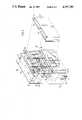
- FIGS. 1 and 2are respectively a perspective view along line II--II in FIG. 1 and cross-sectional view of a first embodiment of the invention
- FIGS. 3 to 6are respectively a perspective front view, perspective back view and cross-sectional views along lines V--V and VI--VI in FIG. 3 of a second embodiment of the invention.
- a first embodiment according to the present inventionhas an array of daughter wiring boards 1b each comprising a plurality of components 1a, mother boards 3 having, the daughter wiring boards 1b inserted thereon, and connectors 2 for connecting daughter wiring boards 1b to mother boards 3.
- Supports 7support a plurality of mother boards 3 of the array.
- An upper intake unit 5 with blowers 6is mounted in the upper position of the equipment relative to the boards 1b and 3, connectors 2, and supports 7.
- a lower intake unit 4 with blowers 6is mounted in the lower position relative to the array of boards 1b and 3, connectors 2, and supports 7.
- Covers 8are fixed to the supports 7 by inwardly extending flanges and have exhaust ports 9.
- a divider plate 8c fixed to the appropriate inner wall portion of the supports 7separates the air flow paths from the respective blowers to prevent mixing of the air flow from the upper portion into the lower portion and also prevent mixing of the air flow from the lower portion into the upper portion. This is illustrated in FIG. 2 which is a sectional view along line II--II of FIG. 1.
- Guide plates 8a and 8b fixed to the cover 8direct the warmed air in the flow path to ambient exhaust.
- FIG. 2illustrates temperatures in various zones by T0, T0', T 1 , T 2 , T 3 , and T 4 .
- the differentialsare given by ⁇ T 1 , ⁇ T 2 , ⁇ T 3 , and ⁇ T 4 .
- Cool air from the lower position of the equipmentis introduced by the blowers 6 of the unit 4.
- the cooling airpasses through at the position (A) in the direction of the arrow and cools the lower mounted electric components 1a mounted on the daughter wiring boards 1b.
- the air warmed by the heat produced from the electric components 1ais delivered from position (B) into the exhaust port by guide of the guide plate 8b.
- cooling air from the upper position of this equipmentis introduced by the blowers 6 of the unit 5.
- the air flowpasses through position (D) in the direction of an arrow and cools the upper electronic components 1a mounted on the daughter wiring boards 1b.
- the air warmed by the heat produced from the upper electric components 1ais delivered from the position (C) into the exhaust port 9 by guide of the guide plate 8a.
- FIGS. 3 and 4are perspective front and rear views of the second embodiment.
- FIGS. 5 and 6are two sectional views taken respectively along lines V--V and VI--VI in FIG. 3.
- the wiring boards 110are fixed to a frame 112 which has a larger front shape than that of the board 111, and has a sleeve portion 112a.
- a front cover 113is fixed to the sleeve portion 112a, so that an intake duct 114 is formed by the frame 112 and the cover 113.
- a plurality of blowersare fixed to the sleeve portion 112a, and are located beside the intake duct 114.
- the intake portions of the blowersare connected to an inlet portion 116 of the sleeve portion 112a and the exhaust portions of the blowers are connected to a conduit path 117 of the frame 112.
- the conduit path 117is rectangular in shape when viewed in cross-section.
- the blowersmove cooling air into and through the inlet portion 116 and exhaust cooling air to the wiring boards 110 through the conduit path 117.
- Seal plates 118 fixed to the wiring boards 110 and an inner cover 119 fixed to the frame 112enclose the wiring board 110 and the conduit path 117.
- a path 120(illustrated in the horizontal cross-sectional view FIG. 5) is formed which guides the cooling air in horizontal direction on the back sides along the mounting surface of the wiring boards 110 from the conduit path 117.
- the path 120is divided into two parts by a vertical separator plate 121 in the central portion of the path 120.
- Two outer rear covers 122have a U-shape, and include the inner cover 119 joined together by flange portions, so that an exhaust duct 123 having a duct width M (FIG. 5) is formed by the combined outer covers 122 and the inner cover 119.
- the lower portion of the exhaust duct 123is sealed and the upper portion of the exhaust duct 123 is open.
- the air warmed by the heat produced from the component array 111is delivered from the path 120 into the exhaust duct 123 via an outlet portion 124.
- FIG. 6also illustrates cable connectors 125 fixed to the wiring boards 110, and connect the wiring boards mounted on other equipment through signal cable 126.
- Wire lines 128connect signal pins 127 mounted the wiring boards in the same equipment. Those components are also subjected to cooling air due to eddies and convection currents.
- the air flow passing through ductwill now be explained.
- the cooling air introduced through the intake duct 114flows in the direction of the arrow from the blower 115 into the zones 120 between components 111 and through the conduit path 117.
- the cooling air passing through the path 120 in the direction of an arrowcools the components 111 mounted on the wiring boards 110.
- the air warmed by the heat produced from the components 111is delivered from the zones 120 into the exhaust duct 123 through the outlet portion 124.
- the blowers 115are not positioned on the side of the frame 112 and the shape of the conduit path 117 is a rectangle in the perpendicular direction, so that the location of the wiring boards can be close to each other. Accordingly, the distance between one component and another component is reduced more than that of the prior art.
- the area of the exhaust ductis larger than that of ducts used in prior art devices such as in U.S. Pat. No. 4,158,875.
Landscapes
- Engineering & Computer Science (AREA)
- Aviation & Aerospace Engineering (AREA)
- Physics & Mathematics (AREA)
- Thermal Sciences (AREA)
- Microelectronics & Electronic Packaging (AREA)
- Cooling Or The Like Of Electrical Apparatus (AREA)
Abstract
Description
Claims (9)
Applications Claiming Priority (4)
| Application Number | Priority Date | Filing Date | Title |
|---|---|---|---|
| JP59-199434 | 1984-09-26 | ||
| JP19943484AJPS6178199A (en) | 1984-09-26 | 1984-09-26 | Air-cooling device for electronic apparatus |
| JP20713584AJPS6185899A (en) | 1984-10-04 | 1984-10-04 | Electronic device cooling construction |
| JP59-207135 | 1984-10-04 |
Related Parent Applications (1)
| Application Number | Title | Priority Date | Filing Date |
|---|---|---|---|
| US06780496Continuation | 1985-09-26 |
Publications (1)
| Publication Number | Publication Date |
|---|---|
| US4797783Atrue US4797783A (en) | 1989-01-10 |
Family
ID=26511534
Family Applications (1)
| Application Number | Title | Priority Date | Filing Date |
|---|---|---|---|
| US07/106,891Expired - Fee RelatedUS4797783A (en) | 1984-09-26 | 1987-10-13 | Air cooling equipment for electronic systems |
Country Status (2)
| Country | Link |
|---|---|
| US (1) | US4797783A (en) |
| FR (1) | FR2570920B1 (en) |
Cited By (51)
| Publication number | Priority date | Publication date | Assignee | Title |
|---|---|---|---|---|
| US5079438A (en)* | 1989-01-30 | 1992-01-07 | Heung Lap Yan | Circuit module fan assembly |
| US5119497A (en)* | 1989-09-22 | 1992-06-02 | Unisys Corp. | Enclosure for computer control unit |
| US5121291A (en)* | 1991-02-13 | 1992-06-09 | Mentor Systems, Inc. | Ventilation system in a portable computer |
| US5150277A (en)* | 1990-05-04 | 1992-09-22 | At&T Bell Laboratories | Cooling of electronic equipment cabinets |
| US5191230A (en)* | 1989-01-30 | 1993-03-02 | Heung Lap Yan | Circuit module fan assembly |
| US5204609A (en)* | 1991-12-16 | 1993-04-20 | Alisauski Daryl J | Battery cooling apparatus |
| US5216361A (en)* | 1991-07-10 | 1993-06-01 | Schlumberger Technologies, Inc. | Modular board test system having wireless receiver |
| US5375038A (en)* | 1994-03-02 | 1994-12-20 | Compaq Computer Corporation | Computer tower unit having internal air flow control baffle structure |
| US5432674A (en)* | 1994-03-02 | 1995-07-11 | Compaq Computer Corporation | Computer tower unit having internal air flow control baffle structure |
| US5544012A (en)* | 1993-12-28 | 1996-08-06 | Kabushiki Kaisha Toshiba | Cooling system for cooling electronic apparatus |
| WO1997038566A1 (en)* | 1996-04-10 | 1997-10-16 | Intergraph Corporation | Removable circuit board with ducted cooling |
| US5751550A (en)* | 1996-04-16 | 1998-05-12 | Compaq Computer Corporation | Ultra-quiet, thermally efficient cooling system for forced air cooled electronics |
| US6459579B1 (en)* | 2001-01-03 | 2002-10-01 | Juniper Networks, Inc. | Apparatus and method for directing airflow in three dimensions to cool system components |
| GB2378584A (en)* | 2001-08-10 | 2003-02-12 | Sun Microsystems Inc | Cooling computer systems |
| US20030030978A1 (en)* | 2001-08-10 | 2003-02-13 | Garnett Paul J. | Cooling computer systems |
| US20030141089A1 (en)* | 2002-01-30 | 2003-07-31 | Gravell Anthony R. | Balanced flow cooling |
| US20030214782A1 (en)* | 2002-05-16 | 2003-11-20 | Osborn Jay K. | Computing apparatus with cooling fan |
| US20030227443A1 (en)* | 2002-06-11 | 2003-12-11 | Fujitsu Limited | Information processing apparatus having battery and penholder |
| KR100401905B1 (en)* | 1996-03-13 | 2004-01-31 | 리탈 게엠베하 운트 코.카게 | Cooler for fitting to the rear or side wall or the door of a switching cabinet |
| US20040182799A1 (en)* | 2002-12-20 | 2004-09-23 | Agilent Technologies, Inc. | Instrument rack with direct exhaustion |
| US20050195567A1 (en)* | 2004-02-27 | 2005-09-08 | Yamaha Corporation | Air conditioning structure for electrical appliances |
| US20060104024A1 (en)* | 2004-11-18 | 2006-05-18 | Wang David G | Minimization of cooling air preheat for maximum packaging density |
| US20060248380A1 (en)* | 2005-04-27 | 2006-11-02 | Hitachi, Ltd. | Disk array device |
| US20070211428A1 (en)* | 2006-03-08 | 2007-09-13 | Cray Inc. | Multi-stage air movers for cooling computer systems and for other uses |
| US20070218826A1 (en)* | 2006-03-17 | 2007-09-20 | Kell Systems | Noiseproofed and ventilated enclosure for electronics equipment |
| US20070223191A1 (en)* | 2006-03-24 | 2007-09-27 | Fujitsu Limited | Electronic apparatus |
| US20070223201A1 (en)* | 2006-03-24 | 2007-09-27 | Fujitsu Limited | Electronic apparatus |
| US20070274036A1 (en)* | 2006-03-17 | 2007-11-29 | Kell Systems | Noise Proofed Ventilated Air Intake Chamber for Electronics Equipment Enclosure |
| US20090135561A1 (en)* | 2007-11-23 | 2009-05-28 | Cheng-Chung Chang | Electronic device with airflow field |
| US20090154091A1 (en)* | 2007-12-17 | 2009-06-18 | Yatskov Alexander I | Cooling systems and heat exchangers for cooling computer components |
| US20090201644A1 (en)* | 2008-02-11 | 2009-08-13 | Kelley Douglas P | Systems and associated methods for cooling computer components |
| US20090244826A1 (en)* | 2008-04-01 | 2009-10-01 | Doll Wade J | Airflow management apparatus for computer cabinets and associated methods |
| US20090303687A1 (en)* | 2008-06-05 | 2009-12-10 | Vetco Gray Controls Limited | Subsea Electronics Module |
| US20100003911A1 (en)* | 2008-06-19 | 2010-01-07 | Panduit Corp. | Passive Cooling Systems for Network Cabinet |
| US20100097751A1 (en)* | 2008-10-17 | 2010-04-22 | Doll Wade J | Air conditioning systems for computer systems and associated methods |
| US20100097752A1 (en)* | 2008-10-17 | 2010-04-22 | Doll Wade J | Airflow intake systems and associated methods for use with computer cabinets |
| US20120045168A1 (en)* | 2010-08-19 | 2012-02-23 | Kabushiki Kaisha Toshiba | Flexible optoelectronic interconnection board and flexible optoelectronic interconnection module |
| CN102724848A (en)* | 2012-05-31 | 2012-10-10 | 华为技术有限公司 | Network cabinet |
| US20120329378A1 (en)* | 2006-04-27 | 2012-12-27 | Eaton Corporation | Assembly for Extracting Heat from a Housing for Electronic Equipment |
| US8472181B2 (en) | 2010-04-20 | 2013-06-25 | Cray Inc. | Computer cabinets having progressive air velocity cooling systems and associated methods of manufacture and use |
| US8767400B2 (en) | 2011-06-27 | 2014-07-01 | The Bergquist Torrington Company | Cooling module with parallel blowers |
| US9253928B2 (en) | 2011-06-27 | 2016-02-02 | Henkel IP & Holding GmbH | Cooling module with parallel blowers |
| US9795061B2 (en) | 2013-03-15 | 2017-10-17 | Switch, Ltd. | Data center facility design configuration |
| US10028415B1 (en)* | 2007-06-14 | 2018-07-17 | Switch, Ltd. | Electronic equipment data center and server co-location facility configurations and method of using the same |
| US10178796B2 (en) | 2007-06-14 | 2019-01-08 | Switch, Ltd. | Electronic equipment data center or co-location facility designs and methods of making and using the same |
| US10356968B2 (en) | 2007-06-14 | 2019-07-16 | Switch, Ltd. | Facility including externally disposed data center air handling units |
| US10888034B2 (en) | 2007-06-14 | 2021-01-05 | Switch, Ltd. | Air handling unit with a canopy thereover for use with a data center and method of using the same |
| US11275413B2 (en) | 2007-06-14 | 2022-03-15 | Switch, Ltd. | Data center air handling unit including uninterruptable cooling fan with weighted rotor and method of using the same |
| DE102020124947A1 (en) | 2020-09-24 | 2022-03-24 | Rolf Eggers | Air cooling arrangement for cooling electronic components |
| CN115426864A (en)* | 2022-11-04 | 2022-12-02 | 苏州恒美电子科技股份有限公司 | Space integrated form platformization rack that dispels heat fast |
| US11825627B2 (en) | 2016-09-14 | 2023-11-21 | Switch, Ltd. | Ventilation and air flow control with heat insulated compartment |
Families Citing this family (5)
| Publication number | Priority date | Publication date | Assignee | Title |
|---|---|---|---|---|
| US4672509A (en)* | 1986-08-07 | 1987-06-09 | Ncr Corporation | Air cooling assembly in an electronic system enclosure |
| FR2609233A1 (en)* | 1986-12-30 | 1988-07-01 | Bull Sa | DEVICE FOR VENTILATION OF COMPONENTS ARRANGED ON A PLATE |
| US5207613A (en)* | 1991-07-08 | 1993-05-04 | Tandem Computers Incorporated | Method and apparatus for mounting, cooling, interconnecting, and providing power and data to a plurality of electronic modules |
| US5237484A (en)* | 1991-07-08 | 1993-08-17 | Tandem Computers Incorporated | Apparatus for cooling a plurality of electronic modules |
| EP0786930B1 (en)* | 1996-01-23 | 1998-10-28 | Siemens Aktiengesellschaft | Housing for a flat drawer with a fan |
Citations (5)
| Publication number | Priority date | Publication date | Assignee | Title |
|---|---|---|---|---|
| US2412989A (en)* | 1942-07-03 | 1946-12-24 | Standard Telephones Cables Ltd | Multiple rectifier cooling system |
| US3749981A (en)* | 1971-08-23 | 1973-07-31 | Controlled Power Corp | Modular power supply with indirect water cooling |
| US3895215A (en)* | 1973-11-23 | 1975-07-15 | Jerry Dale Gordon | Cabinet for holding food at a controllable temperature |
| US4158875A (en)* | 1977-05-24 | 1979-06-19 | Nippon Electric Co., Ltd. | Air cooling equipment for electronic systems |
| US4386651A (en)* | 1980-12-02 | 1983-06-07 | Autz + Herrmann Metallwaren-Und Maschinenfabrik | Heat exchanger accessory for electronic circuit cabinets |
Family Cites Families (3)
| Publication number | Priority date | Publication date | Assignee | Title |
|---|---|---|---|---|
| DE2247296C3 (en)* | 1972-09-27 | 1975-07-31 | Siemens Ag, 1000 Berlin Und 8000 Muenchen | Cooling device for telecommunications equipment |
| US4233644A (en)* | 1979-06-28 | 1980-11-11 | International Business Machines Corporation | Dual-pull air cooling for a computer frame |
| DE3316978A1 (en)* | 1983-05-09 | 1984-11-15 | Siemens AG, 1000 Berlin und 8000 München | Construction system for dissipating the heat losses from electronic assemblies which are arranged in containers or cabinets |
- 1985
- 1985-09-26FRFR858514287Apatent/FR2570920B1/ennot_activeExpired - Fee Related
- 1987
- 1987-10-13USUS07/106,891patent/US4797783A/ennot_activeExpired - Fee Related
Patent Citations (5)
| Publication number | Priority date | Publication date | Assignee | Title |
|---|---|---|---|---|
| US2412989A (en)* | 1942-07-03 | 1946-12-24 | Standard Telephones Cables Ltd | Multiple rectifier cooling system |
| US3749981A (en)* | 1971-08-23 | 1973-07-31 | Controlled Power Corp | Modular power supply with indirect water cooling |
| US3895215A (en)* | 1973-11-23 | 1975-07-15 | Jerry Dale Gordon | Cabinet for holding food at a controllable temperature |
| US4158875A (en)* | 1977-05-24 | 1979-06-19 | Nippon Electric Co., Ltd. | Air cooling equipment for electronic systems |
| US4386651A (en)* | 1980-12-02 | 1983-06-07 | Autz + Herrmann Metallwaren-Und Maschinenfabrik | Heat exchanger accessory for electronic circuit cabinets |
Non-Patent Citations (2)
| Title |
|---|
| Hammer et al., "Ventilation System for Data Processing Systems", IBM Technical Disclosure Bulletin, vol. 17, No. 9, 2/75 pp. 2529-2530. |
| Hammer et al., Ventilation System for Data Processing Systems , IBM Technical Disclosure Bulletin, vol. 17, No. 9, 2/75 pp. 2529 2530.* |
Cited By (95)
| Publication number | Priority date | Publication date | Assignee | Title |
|---|---|---|---|---|
| US5079438A (en)* | 1989-01-30 | 1992-01-07 | Heung Lap Yan | Circuit module fan assembly |
| US5191230A (en)* | 1989-01-30 | 1993-03-02 | Heung Lap Yan | Circuit module fan assembly |
| US5287009A (en)* | 1989-01-30 | 1994-02-15 | Heung Lap Yan | Circuit module fan assembly |
| US5119497A (en)* | 1989-09-22 | 1992-06-02 | Unisys Corp. | Enclosure for computer control unit |
| US5150277A (en)* | 1990-05-04 | 1992-09-22 | At&T Bell Laboratories | Cooling of electronic equipment cabinets |
| US5121291A (en)* | 1991-02-13 | 1992-06-09 | Mentor Systems, Inc. | Ventilation system in a portable computer |
| US5216361A (en)* | 1991-07-10 | 1993-06-01 | Schlumberger Technologies, Inc. | Modular board test system having wireless receiver |
| US5204609A (en)* | 1991-12-16 | 1993-04-20 | Alisauski Daryl J | Battery cooling apparatus |
| US5544012A (en)* | 1993-12-28 | 1996-08-06 | Kabushiki Kaisha Toshiba | Cooling system for cooling electronic apparatus |
| US5375038A (en)* | 1994-03-02 | 1994-12-20 | Compaq Computer Corporation | Computer tower unit having internal air flow control baffle structure |
| US5432674A (en)* | 1994-03-02 | 1995-07-11 | Compaq Computer Corporation | Computer tower unit having internal air flow control baffle structure |
| KR100401905B1 (en)* | 1996-03-13 | 2004-01-31 | 리탈 게엠베하 운트 코.카게 | Cooler for fitting to the rear or side wall or the door of a switching cabinet |
| WO1997038566A1 (en)* | 1996-04-10 | 1997-10-16 | Intergraph Corporation | Removable circuit board with ducted cooling |
| US5822188A (en)* | 1996-04-10 | 1998-10-13 | Intergraph Corporation | Removable circuit board with ducted cooling |
| US5751550A (en)* | 1996-04-16 | 1998-05-12 | Compaq Computer Corporation | Ultra-quiet, thermally efficient cooling system for forced air cooled electronics |
| US6459579B1 (en)* | 2001-01-03 | 2002-10-01 | Juniper Networks, Inc. | Apparatus and method for directing airflow in three dimensions to cool system components |
| GB2378584A (en)* | 2001-08-10 | 2003-02-12 | Sun Microsystems Inc | Cooling computer systems |
| US20030030978A1 (en)* | 2001-08-10 | 2003-02-13 | Garnett Paul J. | Cooling computer systems |
| US20030030976A1 (en)* | 2001-08-10 | 2003-02-13 | Garnett Paul J. | Cooling flow |
| US20030030975A1 (en)* | 2001-08-10 | 2003-02-13 | Graham Bestwick | Computer system cooling |
| GB2378584B (en)* | 2001-08-10 | 2003-09-03 | Sun Microsystems Inc | Cooling computer systems |
| US6924977B2 (en) | 2001-08-10 | 2005-08-02 | Sun Microsystems, Inc. | Computer system cooling |
| US6778386B2 (en) | 2001-08-10 | 2004-08-17 | Sun Microsystems, Inc. | Cooling computer systems |
| US20030141089A1 (en)* | 2002-01-30 | 2003-07-31 | Gravell Anthony R. | Balanced flow cooling |
| US6900387B2 (en)* | 2002-01-30 | 2005-05-31 | Sun Microsystems, Inc. | Balanced flow cooling |
| US6975509B2 (en) | 2002-05-16 | 2005-12-13 | Sun Microsystems, Inc. | Computing apparatus with cooling fan |
| US20030214782A1 (en)* | 2002-05-16 | 2003-11-20 | Osborn Jay K. | Computing apparatus with cooling fan |
| US20030227443A1 (en)* | 2002-06-11 | 2003-12-11 | Fujitsu Limited | Information processing apparatus having battery and penholder |
| US7136050B2 (en)* | 2002-06-11 | 2006-11-14 | Fujitsu Limited | Information processing apparatus having battery and penholder |
| US20040182799A1 (en)* | 2002-12-20 | 2004-09-23 | Agilent Technologies, Inc. | Instrument rack with direct exhaustion |
| US7182208B2 (en)* | 2002-12-20 | 2007-02-27 | Agilent Technologies, Inc. | Instrument rack with direct exhaustion |
| US20050195567A1 (en)* | 2004-02-27 | 2005-09-08 | Yamaha Corporation | Air conditioning structure for electrical appliances |
| US7245489B2 (en)* | 2004-02-27 | 2007-07-17 | Yamaha Corporation | Air conditioning structure for electrical appliances |
| US20060104024A1 (en)* | 2004-11-18 | 2006-05-18 | Wang David G | Minimization of cooling air preheat for maximum packaging density |
| US7236362B2 (en)* | 2004-11-18 | 2007-06-26 | Ncr Corporation | Minimization of cooling air preheat for maximum packaging density |
| US20060248380A1 (en)* | 2005-04-27 | 2006-11-02 | Hitachi, Ltd. | Disk array device |
| US7630198B2 (en) | 2006-03-08 | 2009-12-08 | Cray Inc. | Multi-stage air movers for cooling computer systems and for other uses |
| US20070211428A1 (en)* | 2006-03-08 | 2007-09-13 | Cray Inc. | Multi-stage air movers for cooling computer systems and for other uses |
| US20070274036A1 (en)* | 2006-03-17 | 2007-11-29 | Kell Systems | Noise Proofed Ventilated Air Intake Chamber for Electronics Equipment Enclosure |
| US7379298B2 (en) | 2006-03-17 | 2008-05-27 | Kell Systems | Noise proofed ventilated air intake chamber for electronics equipment enclosure |
| US7379299B2 (en) | 2006-03-17 | 2008-05-27 | Kell Systems | Noiseproofed and ventilated enclosure for electronics equipment |
| US20080144280A1 (en)* | 2006-03-17 | 2008-06-19 | Kell Systems | Noiseproofed and Ventilated Air Intake Chamber for Electronics Equipment Enclosure |
| US20070218826A1 (en)* | 2006-03-17 | 2007-09-20 | Kell Systems | Noiseproofed and ventilated enclosure for electronics equipment |
| US7782612B2 (en) | 2006-03-17 | 2010-08-24 | Kell Systems | Noiseproofed and ventilated air intake chamber for electronics equipment enclosure |
| US20070223201A1 (en)* | 2006-03-24 | 2007-09-27 | Fujitsu Limited | Electronic apparatus |
| US7319596B2 (en)* | 2006-03-24 | 2008-01-15 | Fujitsu Limited | Electronic apparatus |
| US7365977B2 (en)* | 2006-03-24 | 2008-04-29 | Fujitsu Limited | Electronic apparatus |
| US20070223191A1 (en)* | 2006-03-24 | 2007-09-27 | Fujitsu Limited | Electronic apparatus |
| US20120329378A1 (en)* | 2006-04-27 | 2012-12-27 | Eaton Corporation | Assembly for Extracting Heat from a Housing for Electronic Equipment |
| US10588245B2 (en)* | 2006-04-27 | 2020-03-10 | Eaton Intelligent Power Limited | Assembly for extracting heat from a housing for electronic equipment |
| US12222782B2 (en) | 2007-06-14 | 2025-02-11 | Switch, Ltd. | Data center air handling unit including uninterruptable cooling fan with weighted rotor and method of using the same |
| US11275413B2 (en) | 2007-06-14 | 2022-03-15 | Switch, Ltd. | Data center air handling unit including uninterruptable cooling fan with weighted rotor and method of using the same |
| US10888034B2 (en) | 2007-06-14 | 2021-01-05 | Switch, Ltd. | Air handling unit with a canopy thereover for use with a data center and method of using the same |
| US11622484B2 (en) | 2007-06-14 | 2023-04-04 | Switch, Ltd. | Data center exterior wall penetrating air handling technology |
| US10356939B2 (en) | 2007-06-14 | 2019-07-16 | Switch, Ltd. | Electronic equipment data center or co-location facility designs and methods of making and using the same |
| US11889630B2 (en) | 2007-06-14 | 2024-01-30 | Switch, Ltd. | Data center facility including external wall penetrating air handling units |
| US10356968B2 (en) | 2007-06-14 | 2019-07-16 | Switch, Ltd. | Facility including externally disposed data center air handling units |
| US10178796B2 (en) | 2007-06-14 | 2019-01-08 | Switch, Ltd. | Electronic equipment data center or co-location facility designs and methods of making and using the same |
| US10028415B1 (en)* | 2007-06-14 | 2018-07-17 | Switch, Ltd. | Electronic equipment data center and server co-location facility configurations and method of using the same |
| US20090135561A1 (en)* | 2007-11-23 | 2009-05-28 | Cheng-Chung Chang | Electronic device with airflow field |
| US10082845B2 (en) | 2007-12-17 | 2018-09-25 | Cray, Inc. | Cooling systems and heat exchangers for cooling computer components |
| US9596789B2 (en) | 2007-12-17 | 2017-03-14 | Cray Inc. | Cooling systems and heat exchangers for cooling computer components |
| US20090154091A1 (en)* | 2007-12-17 | 2009-06-18 | Yatskov Alexander I | Cooling systems and heat exchangers for cooling computer components |
| US9288935B2 (en) | 2007-12-17 | 2016-03-15 | Cray Inc. | Cooling systems and heat exchangers for cooling computer components |
| US20100317279A1 (en)* | 2007-12-17 | 2010-12-16 | Yatskov Alexander I | Cooling systems and heat exchangers for cooling computer components |
| US8820395B2 (en) | 2007-12-17 | 2014-09-02 | Cray Inc. | Cooling systems and heat exchangers for cooling computer components |
| US10588246B2 (en) | 2008-02-11 | 2020-03-10 | Cray, Inc. | Systems and associated methods for controllably cooling computer components |
| US20090201644A1 (en)* | 2008-02-11 | 2009-08-13 | Kelley Douglas P | Systems and associated methods for cooling computer components |
| US9420729B2 (en) | 2008-02-11 | 2016-08-16 | Cray Inc. | Systems and associated methods for controllably cooling computer components |
| US8170724B2 (en) | 2008-02-11 | 2012-05-01 | Cray Inc. | Systems and associated methods for controllably cooling computer components |
| US7898799B2 (en) | 2008-04-01 | 2011-03-01 | Cray Inc. | Airflow management apparatus for computer cabinets and associated methods |
| US20090244826A1 (en)* | 2008-04-01 | 2009-10-01 | Doll Wade J | Airflow management apparatus for computer cabinets and associated methods |
| US8493741B2 (en)* | 2008-06-05 | 2013-07-23 | Vetco Gray Controls Limited | Subsea electronics module |
| US20090303687A1 (en)* | 2008-06-05 | 2009-12-10 | Vetco Gray Controls Limited | Subsea Electronics Module |
| US10058011B2 (en)* | 2008-06-19 | 2018-08-21 | Panduit Corp. | Passive cooling systems for network cabinet |
| US20100003911A1 (en)* | 2008-06-19 | 2010-01-07 | Panduit Corp. | Passive Cooling Systems for Network Cabinet |
| US7903403B2 (en) | 2008-10-17 | 2011-03-08 | Cray Inc. | Airflow intake systems and associated methods for use with computer cabinets |
| US20100097751A1 (en)* | 2008-10-17 | 2010-04-22 | Doll Wade J | Air conditioning systems for computer systems and associated methods |
| US8537539B2 (en) | 2008-10-17 | 2013-09-17 | Cray Inc. | Air conditioning systems for computer systems and associated methods |
| US20100097752A1 (en)* | 2008-10-17 | 2010-04-22 | Doll Wade J | Airflow intake systems and associated methods for use with computer cabinets |
| US8081459B2 (en) | 2008-10-17 | 2011-12-20 | Cray Inc. | Air conditioning systems for computer systems and associated methods |
| US9310856B2 (en) | 2010-04-20 | 2016-04-12 | Cray Inc. | Computer cabinets having progressive air velocity cooling systems and associated methods of manufacture and use |
| US8472181B2 (en) | 2010-04-20 | 2013-06-25 | Cray Inc. | Computer cabinets having progressive air velocity cooling systems and associated methods of manufacture and use |
| US20120045168A1 (en)* | 2010-08-19 | 2012-02-23 | Kabushiki Kaisha Toshiba | Flexible optoelectronic interconnection board and flexible optoelectronic interconnection module |
| US8767400B2 (en) | 2011-06-27 | 2014-07-01 | The Bergquist Torrington Company | Cooling module with parallel blowers |
| US9253928B2 (en) | 2011-06-27 | 2016-02-02 | Henkel IP & Holding GmbH | Cooling module with parallel blowers |
| CN102724848B (en)* | 2012-05-31 | 2014-12-03 | 华为技术有限公司 | Network cabinet |
| WO2013177933A1 (en)* | 2012-05-31 | 2013-12-05 | 华为技术有限公司 | Network cabinet |
| CN102724848A (en)* | 2012-05-31 | 2012-10-10 | 华为技术有限公司 | Network cabinet |
| US9795061B2 (en) | 2013-03-15 | 2017-10-17 | Switch, Ltd. | Data center facility design configuration |
| US11825627B2 (en) | 2016-09-14 | 2023-11-21 | Switch, Ltd. | Ventilation and air flow control with heat insulated compartment |
| US12274021B2 (en) | 2016-09-14 | 2025-04-08 | Switch, Ltd. | Ventilation and air flow control with heat insulated compartment |
| DE102020124947A1 (en) | 2020-09-24 | 2022-03-24 | Rolf Eggers | Air cooling arrangement for cooling electronic components |
| DE102020124947B4 (en) | 2020-09-24 | 2022-09-01 | Rolf Eggers | Air cooling arrangement and method for cooling electronic components |
| CN115426864A (en)* | 2022-11-04 | 2022-12-02 | 苏州恒美电子科技股份有限公司 | Space integrated form platformization rack that dispels heat fast |
Also Published As
| Publication number | Publication date |
|---|---|
| FR2570920A1 (en) | 1986-03-28 |
| FR2570920B1 (en) | 1994-09-30 |
Similar Documents
| Publication | Publication Date | Title |
|---|---|---|
| US4797783A (en) | Air cooling equipment for electronic systems | |
| US5544012A (en) | Cooling system for cooling electronic apparatus | |
| EP1164825B1 (en) | Cooling of electronic equipment | |
| US5940266A (en) | Bi-directional cooling arrangement for use with an electronic component enclosure | |
| EP0274486B1 (en) | Parallel-flow air system for cooling electronic equipment | |
| US6989988B2 (en) | Duct for cooling multiple components in a processor-based device | |
| US3874444A (en) | Duo-baffle air separator apparatus | |
| US4399484A (en) | Integral electric module and assembly jet cooling system | |
| US5063476A (en) | Apparatus for controlled air-impingement module cooling | |
| US4122508A (en) | Modular printed circuit board assembly having cooling means incorporated therein | |
| US4935845A (en) | Electronic circuit module with improved cooling | |
| US4158875A (en) | Air cooling equipment for electronic systems | |
| EP0020912A1 (en) | Air cooled electronic assemblies | |
| EP0031419B1 (en) | Air-cooled hybrid electronic package | |
| EP0427656A2 (en) | Improved apparatus for cooling electronics components | |
| CA2275875C (en) | Component holder with circulating air cooling of electrical components | |
| JPH07506222A (en) | modular packaging equipment | |
| US4835658A (en) | Device for ventilating components arranged in rows on a substrate | |
| JPH073916B2 (en) | Electronic circuit module mounting structure | |
| EP0020084B1 (en) | An electronics rack cooled by natural air convection | |
| EP0268137B1 (en) | Metal-clad switchgear | |
| JPS62257796A (en) | Cooling device for electronic parts | |
| US5424914A (en) | Through backplane impingement cooling apparatus | |
| JP3006361B2 (en) | Heat sink, electronic device using the same, and electronic computer using the electronic device | |
| JP2806373B2 (en) | Electronic equipment cooling structure |
Legal Events
| Date | Code | Title | Description |
|---|---|---|---|
| AS | Assignment | Owner name:NEC CORPORATION, 33-1, SHIBA 5-CHOME, MINATO-KU TO Free format text:ASSIGNMENT OF ASSIGNORS INTEREST.;ASSIGNORS:KOHMOTO, MITSUO;MATSUO, YOHICHI;REEL/FRAME:004982/0054 Effective date:19850924 Owner name:NEC CORPORATION, JAPAN Free format text:ASSIGNMENT OF ASSIGNORS INTEREST;ASSIGNORS:KOHMOTO, MITSUO;MATSUO, YOHICHI;REEL/FRAME:004982/0054 Effective date:19850924 | |
| FEPP | Fee payment procedure | Free format text:PAYOR NUMBER ASSIGNED (ORIGINAL EVENT CODE: ASPN); ENTITY STATUS OF PATENT OWNER: LARGE ENTITY | |
| FPAY | Fee payment | Year of fee payment:4 | |
| FEPP | Fee payment procedure | Free format text:PAYOR NUMBER ASSIGNED (ORIGINAL EVENT CODE: ASPN); ENTITY STATUS OF PATENT OWNER: LARGE ENTITY Free format text:PAYER NUMBER DE-ASSIGNED (ORIGINAL EVENT CODE: RMPN); ENTITY STATUS OF PATENT OWNER: LARGE ENTITY | |
| FPAY | Fee payment | Year of fee payment:8 | |
| REMI | Maintenance fee reminder mailed | ||
| LAPS | Lapse for failure to pay maintenance fees | ||
| FP | Lapsed due to failure to pay maintenance fee | Effective date:20010110 | |
| STCH | Information on status: patent discontinuation | Free format text:PATENT EXPIRED DUE TO NONPAYMENT OF MAINTENANCE FEES UNDER 37 CFR 1.362 |