US4796997A - Method and system for high-speed, 3-D imaging of an object at a vision station - Google Patents
Method and system for high-speed, 3-D imaging of an object at a vision stationDownload PDFInfo
- Publication number
- US4796997A US4796997AUS07/052,841US5284187AUS4796997AUS 4796997 AUS4796997 AUS 4796997AUS 5284187 AUS5284187 AUS 5284187AUS 4796997 AUS4796997 AUS 4796997A
- Authority
- US
- United States
- Prior art keywords
- signal
- electrical signals
- split
- imaging
- light
- Prior art date
- Legal status (The legal status is an assumption and is not a legal conclusion. Google has not performed a legal analysis and makes no representation as to the accuracy of the status listed.)
- Expired - Lifetime
Links
Images


Classifications
- G—PHYSICS
- G01—MEASURING; TESTING
- G01B—MEASURING LENGTH, THICKNESS OR SIMILAR LINEAR DIMENSIONS; MEASURING ANGLES; MEASURING AREAS; MEASURING IRREGULARITIES OF SURFACES OR CONTOURS
- G01B11/00—Measuring arrangements characterised by the use of optical techniques
- G01B11/24—Measuring arrangements characterised by the use of optical techniques for measuring contours or curvatures
Definitions
- This inventionrelates to method and apparatus for imaging an object at a vision station to develop dimensional information associated with the object and, in particular, to method and apparatus for imaging an object at a vision station to develop dimensional information associated with the object by projecting a beam of controlled light at the object and detecting the position of the laser spot in the image plane.
- Depth detection techniquesare categorized as passive when a controlled source of radiation is not required, or active if a beam of radiant energy is involved. Passive ranging techniques avoid putting constraints on the observed objects or their environment and, consequently, have been the subject of much research in both computer vision and psychophysics. Methods based on stereo disparity, camera motion, surface reflectants, texture gradients, shadows and occlusions have been explored. These techniques often have psychophysical correlates. For example, depth perception in the human visual system is believed to be based upon these types of cues.
- Active depth detection techniqueseliminate the correspondence problem and measure the depth directly by using a beam of energy and recording the time of flight (sonar and radar applications such as shown in U.S. Pat. No. 4,212,534). Depth may also be measured through displacement (triangulation and grid coding), phase shift of a laser beam compared to a reference beam (laser radar), or shadow length (directional illumination). Extensive computation for a depth map is avoided and the information processing task is reduced to extraction of three-dimensional features, representation of the surfaces and scene analysis operations. In the application where the use of intensity or color improve classification, both range and intensity data may be used.
- the triangulation or structured light conceptoffers a great potential for acquiring a dense, high-resolution (approximately 1 mil and finer) 3-D image at high data rates (10 MHz) at a relatively low cost.
- the triangulation conceptis one of the oldest depth detection techniques which exists, but which continues to undergo new developments.
- the laser radar approachis relatively new to machine vision. While the laser radar approach has some advantages, its relatively low data rate and high cost make this approach somewhat unwieldy for high resolution application; as the modulation frequency is increased to the GHz range, high resolution imaging becomes relatively difficult to implement in a cost-effective way.
- the triangulation methodis relatively simple and has an inherently high resolution capability.
- the vision system described thereinincludes a linear array sensor which is positioned so that a line of light is visible only if a reference plane is illuminated. If an object is present, then the light beam is broken. A second line source is used to minimize shadows. As the object is scanned with a linear sensor, a binary image is produced and the presence and orientation of the object is then determined.
- One commercially available 3-D vision system which produces height measurementsincludes a microprocessor-based, laser line sectioning system.
- the systemis capable of producing 60 fields of 480 x,y,z coordinates each second which corresponds to approximately 30 KHz data rate.
- Each line of datarequires acquisition of an entire video field. If a one-half inch by one-half inch object is to be imaged at one mil, x,y,z resolution then the maximum speed of the object conveyed on a conveyor belt for 100% inspection of the part is approximately 30 seconds per inch.
- Such a single stripe systemis most useful in gauging and spot checking and the use of multiple stripes in such a system are best for highly constrained scenes which are not likely to change very often. These systems are mostly used for gauging rather than for image processing and 100% inspection. Proper sampling and acquisition of dense three-dimensional information requires the stripes be scanned across the object and imaged with an array camera or line sensor, either of which can limit the data rate. Tradeoffs between speed, resolution and dynamic range are a necessary consequence of the use of a multiple stripe system.
- One method for acquiring data in a 3-D vision systemis to replace the line scan or array sensor utilized in most 3-D vision systems with a lateral effect photodiode as illustrated in U.S. Pat. No. 4,375,921.
- the ambiguities which might exist in multiple stripe systemsare not a problem with this technique and the measurement range variation is relatively large. This is true because the entire detector surface is available and there is no requirement to share the detector area as in a multiple stripe system.
- Dual detector devicesi.e. bi-cells which have a 30 MHz bandwidth are available but standard devices are not useful in the basic triangulation concept for imaging under low light conditions at high speed, particularly when large fields of view are examined. These devices are also very sensitive to spot shape and geometric distortions.
- U.S. Pat. Nos. 4,068,955 and 4,192,612disclose a thickness measuring device utilizing well-known trigonometric principles to generate data to give the distance to or the thickness of a remote object.
- beams of lightare directed through beam-splitting mirrors to opposite surfaces of the object to be measured.
- suitable trigonometric rulescan be applied to generate the approximate thickness of the object in question.
- U.S. Pat. No. 4,472,056discloses a shape-detecting apparatus for detecting three-dimensional products or parts such as soldered areas of a printed circuit board, the parts attached to the printed board and bumps in an LSI bonding process.
- the apparatuscomprises a slit projector for projecting a slit bright line image forming lens for forming the bright line image.
- the apparatusalso comprises an image scanning mechanism for the bright line image formed through an image forming lens in a height direction of the object and a one-dimensional image sensing device for self-scanning the bright line image formed therein with an array of image sensing elements orthogonal to the scanning direction by the image scanning mechanism.
- This systemis severely limited by readout time; each 3-D point requires examination at many photodetectors.
- U.S. Pat. No. 4,355,904discloses a device for measuring depth using a pair of photodetectors such as photodiodes and a partially reflective and a partially transmissive filter. The computation of the centroid is done by an analog divider.
- U.S. Pat. No. 4,553,844discloses a method and system in which a spot beam scans an object in one direction and the resulting spot image is detected through observation in a direction transverse the one direction.
- U.S. Pat. No. 4,645,917discloses a swept aperture flying spot profiler.
- the sensor used in the systemis either a photomultiplier or an avalanche diode.
- U.S. Pat. No. 4,349,277discloses a parallax method of wavelength labeling based on optical triangulation.
- a signal processorcalculates a normalized signal that is independent of surface reflectivity and roughness variations.
- U.S. Pat. No. 4,634,879discloses the use of optical triangulation for determining the profile of a surface utilizing two photomultiplier tubes in a flying spot camera system. These are arranged in a "bi-cell" configuration. As an anti-noise feature, amplitude modulation is impressed upon the laser beam and a filter network is used to filter photomultiplier response so as to exclude response to background optical noise.
- An object of the present inventionis to provide an improved method and system for high speed, 3-D imaging of an object at a vision station wherein extremely high speed and sensitivity can be obtained by using photodetectors and a relatively simple and low cost signal processing circuitry having a large dynamic range to develop dimensional information associated with the object.
- Another object of the present inventionis to provide a method and system for imaging an object at a vision station which overcomes many of the limitations of the prior art methods and systems by optically preprocessing the reflected light signal by a set of optical components which improve the quality of the data collected.
- Yet still another object of the present inventionis to provide a method and system for imaging an object at a vision station to develop high resolution, dimensional information associated with the object in a relatively inexpensive and compact fashion and which system can be interfaced with standard, video-rate apparatus.
- a methodfor the high-speed, 3-D imaging of an object at a vision station to develop dimensional information associated with the object.
- the methodcomprises the steps of scanning of controlled light at the surface of the object at a first predetermined angle to generate a corresponding reflected light signal, receiving the reflected light signal at a second angle with a set of optical components, spatially filtering and smoothing the received signal and optically splitting the received light signal into first and second split beams, the second split beam being a reference beam.
- the methodfurther comprises the steps of measuring the amount of radiant energy in the first split beam and the reference beam and producing corresponding first and second electrical signals proportional to the measurements, normalizing the first and second electrical signals to lie within a predetermined range, and computing a centroid value for the first split beam from the normalized signals.
- an imaging systemfor the high-speed, 3-D imaging of an object at a vision station to develop dimensional information associated with the object.
- the systemcomprises a source for scanning a beam of controlled light at the surface of the object at a first predetermined angle to generate a corresponding reflected light signal and a set of optical components for receiving the reflected light signal at a second angle, for spatially filtering and smoothing the received signal and for optically splitting the received light signal into first and second split beams, the second split beam being a reference beam.
- the systemfurther comprises first and second measuring means for measuring the amount of radiant energy in the transmitted portion of the first split beam and the reference beam, respectively, and producing first and second electrical signals proportional to the measurements, respectively.
- Signal processing meansnormalizes the first and second electrical signals to lie within a predetermined range and computes a centroid value for the first split beam from the normalized signals.
- the method described aboveincludes the step of imaging the first and second light beams to first and second adjacent positions, respectively, prior to the step of measuring.
- the sourceis preferably a laser scanner
- the set of optical componentspreferably includes components for optical filtering and position detection
- the first and second measuring meanseach includes a highly sensitive photodetector for converting the radiant energy in its respective split beam into an electrical current.
- Such an imaging systemcan be incorporated into an inspection/gauging product wherein both range and intensity data are acquired. Inspection of stationary large objects at high resolution can be performed utilizing a line scan configuration.
- Such a method and systemprovide high resolution, video rate, full 3-D imaging at a relatively low cost.
- Such method and systemalso provide imaging at low light levels with high-speed circuitry to accommodate a large dynamic range.
- the present inventionovercomes many of the problems of the prior art by (1) spatial smoothing to reduce erroneous readings within a position-sensitive filter, including a cylindrical element for spot/line conversion; (2) including a programmable mask for rejecting multiple scattered light; (3) a high-speed signal processor with wide dynamic range with feedback to modulate the laser source if necessary; (4) use of detectors which allow shot noise performance to be achieved; and (5) modulation of laser source for reduction of noise bandwidth.
- a feedback arrangementis incorporated herein which could be used to extend dynamic range by first acquiring a line of intensity data which is buffered and used to modulate laser amplitude on the subsequent line. Spatial registration is maintained through use of two laser diodes which are precisely offset.
- TTL modulationis used herein and allows for separate signal processing operations to be performed during the "on” and “off” intervals.
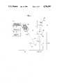
- FIG. 1is a schematic view illustrating the basic triangulation or structured light concept
- FIG. 2is an illustration of two mathematical formulas interrelating various variables illustrated in FIG. 1;
- FIG. 3is a schematic view of a set of optical components, detector assembly and signal processing circuitry for use in the method and system of the present invention
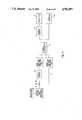
- FIG. 4is a signal processing block diagram illustrating the method and system of the present invention.
- FIG. 5is a detailed schematic diagram of the signal processing circuitry of FIG. 3.
- FIG. 6is a detailed block diagram of the noise suppression circuit of FIG. 5.
- the system 10is positioned at a vision station and includes a controlled source of light such as a laser and collimating lens assembly 12 and a scanner and beam shaping and focusing optics 22 for projecting a series of laser beams 14 at the reflective surface 16 of an object, generally indicated at 18.
- the object 18is supported on a reference, planar surface 20 at the vision station.
- the height Z of the object 18is computed from the projection angle, ⁇ p , and the deflection angle, ⁇ d , at which the reflected beam is incident upon detector element 28 of a detector 24.
- the prior arttypically shows a plurality of detector elements which may comprise a linear array or array sensor or, if a single detector element is provided, may comprise a lateral effect photodiode or bi-cell (dual photo diodes). Dual photodiodes have been used as position sensing devices and are capable of measuring very small depth changes over a limited height range.
- the internal resistance of the diode(which provides the depth sensing and centroid computation capability of the LEP through attenuation of a signal currents) also introduces a noise current which is high enough to become the dominant source of noise in the imaging system. This includes the noise in the dark current which is quite high together with the Johnson noise created by the resistor.
- a good quality commercially available LEPwill produce a noise current which is about an order of magnitude higher than a silicon photodiode with the same area.
- the LEPsare very slow yet the PM tubes and APDs are orders of megnitude more sensitive to light.
- the resistance and the capacitance of the LEP deviceintroduce bandwidth limitations.
- the preferred depth sensing technique described hereinderives position of the light spot centroid through attenuation of light intensity and can be considered the electro-optic counterpart of a lateral effect photodiode but high-speed detectors optimized for sensitivity can also be used.
- the sensitivity of the basic triangulation conceptdepends upon the baseline to height ratio and decreases for steep illumination and viewing angles.
- the sensitivityalso depends upon the spacing between the detector element 28 and the effective focal length of the focusing lens 26 of the detector 24. Increasing the distance of the detector element 28 from the lens 26 increases the sensitivity.
- Scanning methodologies described as “synchronous scanning”, or “telecentric scanning”, “descanning”,allow for considerably relaxation of this tradeoff. Using such geometries allows high resolution depth measurements at steep angles. These scanning geometries can also be used with the position sensing and signal processing system described herein without other modifications. The performance of the system of the invention can be further enhanced with such geometries.
- the effects of shadows and occlusionsare a concern and can limit the achievable range resolution.
- relatively flat surfacessuch as solder paste volume, ink thickness, surface flatness etc., and illumination angle of 30° will typically give the most precise results and occlusion effects will usually be insignificant.
- illumination angles of 10 to 15 degreeswill be desirable. Missing point problems can be reduced with multiple detectors or with autosynchronized geometries to view within 10 degrees.
- the laser 12 and scanner 22 of the present inventionpreferably define a flying spot laser scanner.
- the laser 12is coupled to a modulator 13 to shift the information to a higher frequency where system noise characteristics are better.
- THe modulator 13may perform one of many types of modulation, including sine wave, pulse amplitude, pulse position, etc.
- the laser 12is a solid state laser diode and is "shuttered” with a TTL signal (i.e. TTL modulation).
- TTL signali.e. TTL modulation
- the laser signalis encoded so as to allow separate signal processing functions to be performed during "on” and “off” intervals as described in detail hereinbelow.
- power levelsare 20-30 nW (Class III-B) which are well suited for machine vision applications.
- scanners 22Three types may be utilized: spinning polygon (x-scan) and galvonometer (y-scan) mirrors; linearized resonant scanner (x-scan) and galvonometer (y-scan); or acousto-optic cell (x-scan) and galvonometer (y-scan).
- the scanner 22comprises the latter acousto-optical system because no moving parts are required and the retrace time is very fast.
- Either of the sensorscan be used in conventional triangulation-bases sensing systems having a relatively large baseline-to-height ratio or in narrow angle triangulation systems which utilize telecentric or auto-synchronized scanning methods.
- the optical system 30includes a set of optical components, including an objective lens 31 to collect scattered light from the object and a second diffraction limited lens 32 to focus the collected light onto an intermediate image plane.
- the lenses 36 and 32are conventional. However, each of the lenses 31 and 32 operates at a preferred conjugate.
- the second lens 32can be interchanged to accommodate various reduction and magnification ratios.
- the system 30also includes a mask 33 which, in one embodiment, forms a rectangular aperture 34 (i.e. spatial filter) positioned at the intermediate image plane to reject background noise (i.e. stray light) which arises from secondary reflections from objects outside of the desired instantaneous field of vision of the system.
- the mask 33may be affixed aperture or electromechanical shutter, or, preferably, is a liquid crystal, binary, spatial light modulator which is dynamically reconfigured under software control Such a configuration is useful for inspection of very shiny objects (reflowed solder, wire bond, loops, pin grids, etc.) which are in close proximity from which multiple reflections will be created.
- the mask 33When used with auto-synchronized scanners or in a telecentric scanner (rotating mirrors have moving mechanical parts), the mask 33 is a narrow strip which allows for collection of only the light which is useful for z measurement.
- the spatial filter or stripcan be programmed in a chosen pattern of opaque and transmissive patterns correlated with the height profile of the object to be detected. For example, a height measurement of shiny pins placed on a shiny background will be more reliable if only a narrow strip corresponding to the height range over which properly positioned pins is viewed. Multiple reflections may produce a signal return which is significantly larger than the return produced by useful light. If properly placed, the position of the pin will be reported. If defective, no pin will be found.
- the aperture 34 of the mask 33is no larger than necessary for detection of a specified height range, but is still programmable.
- a fine grained ground glass diffuser 35 of the system 30is located adjacent the intermediate image plane to create a relatively uniform and relatively broad spot of light. Fluctuations in the measured position of the spot as a result of directional scattering or from local variations in a variable filter 36 of the system 30 are spatially averaged and therefore minimized. THis is analogous to low pass filtering in electronic systems.
- variable filter 36which is utilized as a position dependent transmission device produces a measurement of spot centroid location and is relatively insensitive to focus and the shape of the intensity distribution.
- the variable filter 36can be fabricated with a transmission function which is linear with position or as a filter which has a linear density characteristic (i.e. logarithmic transmission with position).
- a nonlinear computation approachhas a property which allows for compression/expansion of the depth sensitivity throughout the range.
- the filter 36can be utilized in such a was as to allow small height changes to be sensed near the baseline (the most distant z coordinate) without compromising the depth sensitivity on taller objects. Since the primary use of the filter 36 is as a variable density device, this nonlinear computation is accomplished with a relatively standard type of filter. On the other hand, if linearity of the z measurement is of importance the linear transmission function should be used.
- the system 30further includes a second lens system, generally indicated at 37, which is used to reduce or magnify the intermediate image and transmit (relay) the image through the system 30.
- a cylindrical lens 38allows for additional spatial averaging over the surface of the variable filter by converting the spot of light into a line (i.e., changing aspect ratio).
- a beamsplitter 39is used to produce a reference split beam or signal and another split beam which is transmitted to the filter 36.
- the first split beamis transmitted to the filter 36 in a first channel 40 and the second or reference split beam is transmitted in a second channel 41.
- the second channel 41provides an intensity reference to normalize the data and eliminate the dependence of the height measurement on brightness.
- the system 30can also be fabricated in such a way as to allow both the reference beam and transmitted beam to be produced by a linear variable filter with a metallic coating on its front surface to produce spatial reflection, thereby allowing for splitting and position dependent attenuation with a single optical component.
- a folding mirror systemincluding mirrors 42 and 43 are used to deliver the light beams to a localized area of a detector assembly, generally indicated at 44.
- the connection between the photodetectors 45 and 46 and their associated pre-amplifiers 47 and 48should be as short as possible to minimize stray capacitance for high-speed applications and to avoid mismatches between the signal channels.
- Constant deviation prismscan also be used in place of the mirrors 42 and 43 to simplify system alignment. The short wire lengths are necessary so that the low level signals are not corrupted by noise.
- the laser light signal transmitted by the filter 36 and the light signal reflected by the mirror 43are imaged by conventional field lenses 49 and 50, respectively, onto consistent, predetermined areas on a pair of photodetectors, 45 and 46 of the assembly 44.
- the assembly 44also includes pre-amplifiers 47 and 48, respectively for the photodetectors.
- Each of the photodetectorsis preferably a small area photodiode (i.e. no larger than 3 mm ⁇ 3 mm) having low capacitance and very high shunt resistance, photomultiplier, avalanche photodiode or intensified detector of a detector element and pre-amplifier combination.
- Such a photodiodepreferably has at least 300 MHz cutoff frequency, corresponding to rise times of 1 nanosecond or less.
- the high speed, low noise pre-amplifier part of the combinationoperates at video rates.
- An "optical bi-cell"can be formed with a slight modification of the arrangement in FIG. 3. This is done by eliminating the variable filter 36 and introducing a slight position offset of the photodetectors 45 and 46.
- the bi-cell detectoris useful for obtaining good height resolution when only a narrow range must be sensed (e.g. traces on circuit board, flatness detection, etc.) and is a complementary approach to the variable density filter 36 which provides high resolution over a relatively large depth of field and a direct measurement of the light spot centroid position.
- the spatial averaging obtained with the diffuser 35is required, in general, to make the bi-cell approach robust because measurement errors will be introduced for non-uniform intensity distributions which result from scattering or from geometric (angular) distortions.
- a commercially available analog dividercan be used to determine the ratio at speeds approaching video frame rates. Such dividers, however, require the sum of V 1 +V 2 (denominator) vary over only a small range (typically 3:1) if high accuracy is to be maintained. A typical scene to be imaged will contain reflectivity variations which are much greater than this range. For instance, printed circuit board components and backgrounds will produce V 1 +V 2 signals which vary by a few orders of magnitude representing the approximate useful diffuse reflectivity variations from 0.5% to 100%. In addition, specular returns will produce a much larger variation and must be identified since the resulting Z value is incorrect, whereas very low photon limited signal returns almost result in division by 0.
- the dynamic range of the measuring systemis sufficient to accommodate diffuse reflectivity variations from a fraction of a percent to 100% (e.g., substantially greater than the full range of black to white given on standard greyscale test charts).
- a fraction of a percent to 100%e.g., substantially greater than the full range of black to white given on standard greyscale test charts.
- the vision system in such an applicationi.e. robot navigation
- the system describedcan be modified to accommodate extended synamic range requirements through feedback to increase or decrease the laser power dependent upon the intensity measured from some point on the object.
- a necessary decrease in the data rate(at least a factor of two) must result and, more importantly, caution must be exercised so that the reflectance measurement corresponds to the exact same physical point on the object as the z measurement.
- high power laser diodesare commercially available with source powers of up to 1 W with very fast rise times, it is feasible to implement a feedback circuit in a practical configuration.
- a source power of 1 Wwould enable the system to measure objects which return signal levels approximately 50X lower than can be measured with the low cost, 20 nw laser diode as previously described.
- dual laser diodes of low and medium power which are precisely offset from each otherare now commercially available.
- Primary application of such dual diodeshas been in inspection of optical disks using a "read after write” technique.
- a medium power laserproduces sufficient signal to noise and these devices can be used.
- the advantage of not requiring additional opto-mechanical hardware to maintain near-perfect registration between the meansis also significant.
- Such a feedback arrangementcan be implemented with "look ahead" capability in the sense that data from the low power laser diode is buffered and subsequently used by a feedback circuit 76 to control the modulation of the high power laser diode by means of pulse amplitude modulation.
- An acousto-optic light modulator instead of the modulator 13is preferred over direct time varying amplitude laser modulation for maintaining stability of the laser source and this device can be regarded as a high-speed, electro-optic shutter.
- signal processing circuitry or unitwhich expands/compresses the variable data in order to obtain the proper Z value and also generates special values indicating incorrect height information.
- the preamplifiers 47 and 48convert the signal currents I 1 , I 2 of the photodetectors 45 and 46, respectively, to corresponding voltages.
- the sum V 1 +V 2is then formed as an analog signal by a summing circuit 54 and then converted into digital form by a non-linear data converter 56 which operates at very high speeds.
- the purpose of converting the data to digital formis to provide an easy method of selecting the gain values (inverse function) required to scale V 1 +V 2 into the approximate 3:1 range required by an analog divider of circuitry 58.
- the ideais similar to that used in AGC (automatic gain control) circuits except that AGC circuits often average the signals for prohibitively long periods and feedback the gain control value which reduces the system bandwidth.
- the output of the converter 56is fed into a gain select logic circuit 57 to provide output signals without feedback.
- the gain value selected with the logic circuit 57are used to "program" a series of high precision amplifier stages 60 and 62 for selecting the gain values to scale the signal V 1 +V 2 into the 3:1 range.
- the circuitry 51includes noise suppression circuits, generally indicated at 64 and 66, for the first and second channels 40 and 41, respectively.
- a first anti-aliasing filter 68 of each noise suppression circuit 64 or 66(as shown in FIG. 6) is applied to smooth out signals variations (high frequency noise) thereby rejecting out-of-band noise.
- This high frequency noiseis rapidly varying compared to the known (modulated) signal.
- these rapid variationsare also removed by a second anti-aliasing filter 68.
- a demodulation stepis performed to reject low frequency noise with sample and hold circuits 70 and 72.
- This noise suppressionalso has the major advantage or providing a "black level reference" for each picture element which is not possible in conventional video systems.
- Black referenceavoids DC offset drift in the signal processing chain. As a result, the fidelity of the signal is dramatically improved.
- a by-product of the methodis an automatic calibration feature. The laser power is controlled with the circuit 13 in such a way that slow term drift in the light level is negligible, thereby establishing a "white reference”. Since the black reference is established for each pixel the entire light range is calibrated on a pixel by pixel basis.
- the signal from the circuitry 51is preferably amplified and coupled to an analog-to-digital converter 78 which, in turn, may be interfaced to a conventional video frame grabber of a larger inspection/gauging product.
- the intensity signal V1+V2 associated with object pointis quantized as before by the non-linear data converter 52 of the circuitry 51 which includes additional outputs 80 for data values outside of the previous range.
- These digital valuesare buffered and through a delay line arrangement within the feedback circuit 76 provide the data necessary to control the modulator 13 so that the appropriate power level is provided to the surface so that the modified V1+V2 signal is in the range of the pre-scalers 60 and 62, noise suppression circuits 64 and 66, and the divider 58.
- the range of the non-linear data converter 56 described hereincan be extended to accommodate an arbitrarily large range within practical requirements of cost, circuit board space, speed requirements, and laser power range.
- the result of this implementationis identical to the previous (3D+greyscale system), except that the 3D data is delayed with respect to the intensity data by a constant known offset.
- a practical choiceis to acquire alternating lines of intensity and depth information.
- imagingcan be performed at high resolution and at video rates to obtain full 3-D information.
- imagingcan be performed at high resolution and at video rates to obtain full 3-D information.
- such a method and systemoffer the potential of accurate video frame rate depth sensing at low cost.
- the detection methodcan be applied to several 3-D imaging geometries in addition to the standard triangulation techniques illustrated in FIGS. 1 and 2.
- shadows and occlusioncan be completely avoided by using a quite simple but clever method utilizing a nearly coaxial illumination beam, light collection system and a CCD detector array.
- the optical systemis a good one, but the detector again severely limits speed, and is incapable of responding to low light levels since the required optical system is inherently inefficient due to a mask which is largely opaque.
- the system disclosed in this inventionhigh speed 3-D sensing at low light levels can be achieved with only a slight increase in the physical size of the optical package.
Landscapes
- Physics & Mathematics (AREA)
- General Physics & Mathematics (AREA)
- Length Measuring Devices By Optical Means (AREA)
- Measurement Of Optical Distance (AREA)
Abstract
Description
Claims (31)
Priority Applications (6)
| Application Number | Priority Date | Filing Date | Title |
|---|---|---|---|
| US07/052,841US4796997A (en) | 1986-05-27 | 1987-05-21 | Method and system for high-speed, 3-D imaging of an object at a vision station |
| EP87304655AEP0247833B1 (en) | 1986-05-27 | 1987-05-26 | Method and system for high-speed, 3-d imaging of an object at a vision station |
| CA000537961ACA1265869A (en) | 1986-05-27 | 1987-05-26 | Method and system for high-speed, 3-d imaging of an object at a vision station |
| DE8787304655TDE3769368D1 (en) | 1986-05-27 | 1987-05-26 | METHOD AND SYSTEM FOR FAST 3-D IMAGE OF AN OBJECT ON AN OPTICAL DETECTION UNIT. |
| GB8808120AGB2204947B (en) | 1987-05-21 | 1988-04-07 | Method and system for high speed, 3-d imaging of an object at a vision station |
| ES8801600AES2007876A6 (en) | 1987-05-21 | 1988-05-20 | Method and system for high speed, 3-D imaging of an object at a vision station |
Applications Claiming Priority (2)
| Application Number | Priority Date | Filing Date | Title |
|---|---|---|---|
| US86673586A | 1986-05-27 | 1986-05-27 | |
| US07/052,841US4796997A (en) | 1986-05-27 | 1987-05-21 | Method and system for high-speed, 3-D imaging of an object at a vision station |
Related Parent Applications (1)
| Application Number | Title | Priority Date | Filing Date |
|---|---|---|---|
| US86673586AContinuation-In-Part | 1986-05-27 | 1986-05-27 |
Publications (1)
| Publication Number | Publication Date |
|---|---|
| US4796997Atrue US4796997A (en) | 1989-01-10 |
Family
ID=26731151
Family Applications (1)
| Application Number | Title | Priority Date | Filing Date |
|---|---|---|---|
| US07/052,841Expired - LifetimeUS4796997A (en) | 1986-05-27 | 1987-05-21 | Method and system for high-speed, 3-D imaging of an object at a vision station |
Country Status (4)
| Country | Link |
|---|---|
| US (1) | US4796997A (en) |
| EP (1) | EP0247833B1 (en) |
| CA (1) | CA1265869A (en) |
| DE (1) | DE3769368D1 (en) |
Cited By (291)
| Publication number | Priority date | Publication date | Assignee | Title |
|---|---|---|---|---|
| US5004929A (en)* | 1988-06-04 | 1991-04-02 | Fujitsu Limited | Optical system for detecting three-dimensional shape |
| US5011960A (en)* | 1988-05-20 | 1991-04-30 | Fujitsu Limited | Wiring pattern detection method and apparatus |
| US5090811A (en)* | 1989-05-31 | 1992-02-25 | General Electric Company | Optical radius gauge |
| US5200799A (en)* | 1989-09-12 | 1993-04-06 | Matsushita Electric Industrial Co., Ltd. | System for optically inspecting conditions of parts packaged on substrate |
| US5200838A (en)* | 1988-05-27 | 1993-04-06 | The University Of Connecticut | Lateral effect imaging system |
| US5500737A (en)* | 1993-07-21 | 1996-03-19 | General Electric Company | Method for measuring the contour of a surface |
| US5555090A (en)* | 1994-10-24 | 1996-09-10 | Adaptive Optics Associates | System for dimensioning objects |
| US5589942A (en)* | 1990-04-05 | 1996-12-31 | Intelligent Automation Systems | Real time three dimensional sensing system |
| US5621807A (en)* | 1993-06-21 | 1997-04-15 | Dornier Gmbh | Intelligent range image camera for object measurement |
| US5638301A (en)* | 1994-06-02 | 1997-06-10 | Ford Motor Company | Method and system for inspecting die sets using free-form inspection techniques |
| WO1997028429A1 (en)* | 1996-01-31 | 1997-08-07 | General Scanning Inc. | Method and system for suppressing unwanted reflections in an optical system |
| US5712803A (en)* | 1995-06-23 | 1998-01-27 | Kreon Industrie | Method of acquiring and digitizing objects through a transparent wall |
| US5859924A (en)* | 1996-07-12 | 1999-01-12 | Robotic Vision Systems, Inc. | Method and system for measuring object features |
| US5870490A (en)* | 1993-04-16 | 1999-02-09 | Nippon Telegraph And Telephone Corporation | Apparatus for extracting pattern features |
| US5911035A (en)* | 1995-04-12 | 1999-06-08 | Tsao; Thomas | Method and apparatus for determining binocular affine disparity and affine invariant distance between two image patterns |
| US5943349A (en)* | 1997-06-27 | 1999-08-24 | Ando Electric Co., Ltd. | Variable wavelength laser device |
| US5946148A (en)* | 1998-10-26 | 1999-08-31 | The United States Of America As Represented By The Secretary Of The Air Force | Variable transmission beamsplitter |
| USRE36560E (en)* | 1988-01-29 | 2000-02-08 | General Scanning, Inc. | Method and system for high-speed, high-resolution, 3-D imaging of an object at a vision station |
| US6120190A (en)* | 1997-11-26 | 2000-09-19 | Lasertron, Inc. | Spatially variable bandpass filter monitoring and feedback control of laser wavelength especially in wavelength division multiplexing communication systems |
| US6243482B1 (en)* | 1996-02-13 | 2001-06-05 | Dornier Gmbh | Obstacle detection system for low-flying airborne craft |
| EP1152261A1 (en)* | 2000-04-28 | 2001-11-07 | CSEM Centre Suisse d'Electronique et de Microtechnique SA | Device and method for spatially resolved photodetection and demodulation of modulated electromagnetic waves |
| US20010048461A1 (en)* | 2000-05-31 | 2001-12-06 | Junichi Noguchi | Image forming apparatus and laser drive control method therein |
| US6345107B1 (en) | 1996-02-21 | 2002-02-05 | Taylor Hobson Limited | Image processing apparatus and method of processing height data to obtain image data using gradient data calculated for a plurality of different points of a surface and adjusted in accordance with a selected angle of illumination |
| US20020018118A1 (en)* | 2000-03-24 | 2002-02-14 | Solvision Inc. | System for simultaneous projections of multiple phase-shifted patterns for the three-dimensional inspection of an object |
| US6502053B1 (en)* | 2000-06-12 | 2002-12-31 | Larry Hardin | Combination passive and active speed detection system |
| US20030123119A1 (en)* | 2001-12-07 | 2003-07-03 | Jds Uniphase Corporation | Optical performance monitoring device |
| US6618135B2 (en)* | 1999-12-03 | 2003-09-09 | Matsushita Electric Industrial Co., Ltd. | Laser beam inspection apparatus |
| US20040193413A1 (en)* | 2003-03-25 | 2004-09-30 | Wilson Andrew D. | Architecture for controlling a computer using hand gestures |
| US20040190005A1 (en)* | 2003-03-31 | 2004-09-30 | Michel Doucet | Position-sensing device for 3-D profilometers |
| US6975747B2 (en) | 2001-08-14 | 2005-12-13 | Acuity Cimatrix, Inc. | Method and system for monitoring and controlling workpieces |
| US20050275893A1 (en)* | 2002-07-16 | 2005-12-15 | Stanley Korn | Method of using printed forms to transmit the information necessary to create electronic forms |
| US20060011725A1 (en)* | 2003-11-13 | 2006-01-19 | Michael Schnee | System for detecting image light intensity reflected off an object in a digital imaging-based bar code symbol reading device |
| US20070216769A1 (en)* | 2006-03-17 | 2007-09-20 | Jerneja Zganec Gros | Active 3D triangulation-based imaging method and device |
| US20080063260A1 (en)* | 2006-09-13 | 2008-03-13 | Chern-Sheng Lin | Measurement method of three-dimentional profiles and reconstruction system thereof using subpixel localization with color gratings and picture-in-picture switching on single display |
| US20080204410A1 (en)* | 2002-02-07 | 2008-08-28 | Microsoft Corporation | Recognizing a motion of a pointing device |
| DE10354078B4 (en)* | 2003-11-19 | 2008-09-04 | Daimler Ag | Clamping device for workpieces for three-dimensional optical surface measurement |
| US20090166684A1 (en)* | 2007-12-26 | 2009-07-02 | 3Dv Systems Ltd. | Photogate cmos pixel for 3d cameras having reduced intra-pixel cross talk |
| US20090268945A1 (en)* | 2003-03-25 | 2009-10-29 | Microsoft Corporation | Architecture for controlling a computer using hand gestures |
| US20090316923A1 (en)* | 2008-06-19 | 2009-12-24 | Microsoft Corporation | Multichannel acoustic echo reduction |
| US20090323059A1 (en)* | 2006-06-29 | 2009-12-31 | Wanxin Sun | SHG Quantification of Matrix-Related Tissue Dynamic and Disease |
| US20100097694A1 (en)* | 2006-07-28 | 2010-04-22 | Bernhard Zimmermann | Method and arrangement for controlled actuation of a microscope, in particular of a laser scanning microscope |
| US20100171813A1 (en)* | 2009-01-04 | 2010-07-08 | Microsoft International Holdings B.V. | Gated 3d camera |
| US20100197391A1 (en)* | 2009-01-30 | 2010-08-05 | Microsoft Corporation | Visual target tracking |
| US20100194872A1 (en)* | 2009-01-30 | 2010-08-05 | Microsoft Corporation | Body scan |
| US20100199229A1 (en)* | 2009-01-30 | 2010-08-05 | Microsoft Corporation | Mapping a natural input device to a legacy system |
| US20100197392A1 (en)* | 2009-01-30 | 2010-08-05 | Microsoft Corporation | Visual target tracking |
| US20100197395A1 (en)* | 2009-01-30 | 2010-08-05 | Microsoft Corporation | Visual target tracking |
| US20100199228A1 (en)* | 2009-01-30 | 2010-08-05 | Microsoft Corporation | Gesture Keyboarding |
| US20100197399A1 (en)* | 2009-01-30 | 2010-08-05 | Microsoft Corporation | Visual target tracking |
| US20100197393A1 (en)* | 2009-01-30 | 2010-08-05 | Geiss Ryan M | Visual target tracking |
| US20100195869A1 (en)* | 2009-01-30 | 2010-08-05 | Microsoft Corporation | Visual target tracking |
| US20100194762A1 (en)* | 2009-01-30 | 2010-08-05 | Microsoft Corporation | Standard Gestures |
| US20100197390A1 (en)* | 2009-01-30 | 2010-08-05 | Microsoft Corporation | Pose tracking pipeline |
| US20100197400A1 (en)* | 2009-01-30 | 2010-08-05 | Microsoft Corporation | Visual target tracking |
| US20100226114A1 (en)* | 2009-03-03 | 2010-09-09 | David Fishbaine | Illumination and imaging system |
| US20100231512A1 (en)* | 2009-03-16 | 2010-09-16 | Microsoft Corporation | Adaptive cursor sizing |
| US20100241998A1 (en)* | 2009-03-20 | 2010-09-23 | Microsoft Corporation | Virtual object manipulation |
| US20100238182A1 (en)* | 2009-03-20 | 2010-09-23 | Microsoft Corporation | Chaining animations |
| US20100281439A1 (en)* | 2009-05-01 | 2010-11-04 | Microsoft Corporation | Method to Control Perspective for a Camera-Controlled Computer |
| US20100277711A1 (en)* | 2009-05-04 | 2010-11-04 | Capella Microsystems, Corp. | Optical quantized distance measuring apparatus and method thereof |
| US20100278393A1 (en)* | 2009-05-01 | 2010-11-04 | Microsoft Corporation | Isolate extraneous motions |
| US20100277411A1 (en)* | 2009-05-01 | 2010-11-04 | Microsoft Corporation | User tracking feedback |
| US20100277489A1 (en)* | 2009-05-01 | 2010-11-04 | Microsoft Corporation | Determine intended motions |
| US20100281438A1 (en)* | 2009-05-01 | 2010-11-04 | Microsoft Corporation | Altering a view perspective within a display environment |
| US20100281436A1 (en)* | 2009-05-01 | 2010-11-04 | Microsoft Corporation | Binding users to a gesture based system and providing feedback to the users |
| US20100277470A1 (en)* | 2009-05-01 | 2010-11-04 | Microsoft Corporation | Systems And Methods For Applying Model Tracking To Motion Capture |
| US20100278431A1 (en)* | 2009-05-01 | 2010-11-04 | Microsoft Corporation | Systems And Methods For Detecting A Tilt Angle From A Depth Image |
| US20100281432A1 (en)* | 2009-05-01 | 2010-11-04 | Kevin Geisner | Show body position |
| US20100295771A1 (en)* | 2009-05-20 | 2010-11-25 | Microsoft Corporation | Control of display objects |
| US20100303290A1 (en)* | 2009-05-29 | 2010-12-02 | Microsoft Corporation | Systems And Methods For Tracking A Model |
| US20100306713A1 (en)* | 2009-05-29 | 2010-12-02 | Microsoft Corporation | Gesture Tool |
| US20100302138A1 (en)* | 2009-05-29 | 2010-12-02 | Microsoft Corporation | Methods and systems for defining or modifying a visual representation |
| US20100303289A1 (en)* | 2009-05-29 | 2010-12-02 | Microsoft Corporation | Device for identifying and tracking multiple humans over time |
| US20100306716A1 (en)* | 2009-05-29 | 2010-12-02 | Microsoft Corporation | Extending standard gestures |
| US20100302365A1 (en)* | 2009-05-29 | 2010-12-02 | Microsoft Corporation | Depth Image Noise Reduction |
| US20100302395A1 (en)* | 2009-05-29 | 2010-12-02 | Microsoft Corporation | Environment And/Or Target Segmentation |
| US20100306714A1 (en)* | 2009-05-29 | 2010-12-02 | Microsoft Corporation | Gesture Shortcuts |
| US20100302145A1 (en)* | 2009-06-01 | 2010-12-02 | Microsoft Corporation | Virtual desktop coordinate transformation |
| US20100306712A1 (en)* | 2009-05-29 | 2010-12-02 | Microsoft Corporation | Gesture Coach |
| US20100306715A1 (en)* | 2009-05-29 | 2010-12-02 | Microsoft Corporation | Gestures Beyond Skeletal |
| US20100303291A1 (en)* | 2009-05-29 | 2010-12-02 | Microsoft Corporation | Virtual Object |
| US20100304813A1 (en)* | 2009-05-29 | 2010-12-02 | Microsoft Corporation | Protocol And Format For Communicating An Image From A Camera To A Computing Environment |
| US20100302247A1 (en)* | 2009-05-29 | 2010-12-02 | Microsoft Corporation | Target digitization, extraction, and tracking |
| US20110007079A1 (en)* | 2009-07-13 | 2011-01-13 | Microsoft Corporation | Bringing a visual representation to life via learned input from the user |
| US20110007142A1 (en)* | 2009-07-09 | 2011-01-13 | Microsoft Corporation | Visual representation expression based on player expression |
| US20110025689A1 (en)* | 2009-07-29 | 2011-02-03 | Microsoft Corporation | Auto-Generating A Visual Representation |
| US20110050885A1 (en)* | 2009-08-25 | 2011-03-03 | Microsoft Corporation | Depth-sensitive imaging via polarization-state mapping |
| US20110055846A1 (en)* | 2009-08-31 | 2011-03-03 | Microsoft Corporation | Techniques for using human gestures to control gesture unaware programs |
| US20110064402A1 (en)* | 2009-09-14 | 2011-03-17 | Microsoft Corporation | Separation of electrical and optical components |
| US20110062309A1 (en)* | 2009-09-14 | 2011-03-17 | Microsoft Corporation | Optical fault monitoring |
| US20110069870A1 (en)* | 2009-09-21 | 2011-03-24 | Microsoft Corporation | Screen space plane identification |
| US20110069221A1 (en)* | 2009-09-21 | 2011-03-24 | Microsoft Corporation | Alignment of lens and image sensor |
| US20110069841A1 (en)* | 2009-09-21 | 2011-03-24 | Microsoft Corporation | Volume adjustment based on listener position |
| US20110079714A1 (en)* | 2009-10-01 | 2011-04-07 | Microsoft Corporation | Imager for constructing color and depth images |
| US20110081044A1 (en)* | 2009-10-07 | 2011-04-07 | Microsoft Corporation | Systems And Methods For Removing A Background Of An Image |
| US20110083108A1 (en)* | 2009-10-05 | 2011-04-07 | Microsoft Corporation | Providing user interface feedback regarding cursor position on a display screen |
| US20110085705A1 (en)* | 2009-05-01 | 2011-04-14 | Microsoft Corporation | Detection of body and props |
| US20110093820A1 (en)* | 2009-10-19 | 2011-04-21 | Microsoft Corporation | Gesture personalization and profile roaming |
| US20110099476A1 (en)* | 2009-10-23 | 2011-04-28 | Microsoft Corporation | Decorating a display environment |
| US20110102438A1 (en)* | 2009-11-05 | 2011-05-05 | Microsoft Corporation | Systems And Methods For Processing An Image For Target Tracking |
| US20110109617A1 (en)* | 2009-11-12 | 2011-05-12 | Microsoft Corporation | Visualizing Depth |
| US20110119640A1 (en)* | 2009-11-19 | 2011-05-19 | Microsoft Corporation | Distance scalable no touch computing |
| US20110154266A1 (en)* | 2009-12-17 | 2011-06-23 | Microsoft Corporation | Camera navigation for presentations |
| US20110151974A1 (en)* | 2009-12-18 | 2011-06-23 | Microsoft Corporation | Gesture style recognition and reward |
| US20110173204A1 (en)* | 2010-01-08 | 2011-07-14 | Microsoft Corporation | Assigning gesture dictionaries |
| US20110169726A1 (en)* | 2010-01-08 | 2011-07-14 | Microsoft Corporation | Evolving universal gesture sets |
| US20110173574A1 (en)* | 2010-01-08 | 2011-07-14 | Microsoft Corporation | In application gesture interpretation |
| US20110175809A1 (en)* | 2010-01-15 | 2011-07-21 | Microsoft Corporation | Tracking Groups Of Users In Motion Capture System |
| US20110182481A1 (en)* | 2010-01-25 | 2011-07-28 | Microsoft Corporation | Voice-body identity correlation |
| US20110184735A1 (en)* | 2010-01-22 | 2011-07-28 | Microsoft Corporation | Speech recognition analysis via identification information |
| US20110190055A1 (en)* | 2010-01-29 | 2011-08-04 | Microsoft Corporation | Visual based identitiy tracking |
| US20110187819A1 (en)* | 2010-02-02 | 2011-08-04 | Microsoft Corporation | Depth camera compatibility |
| US20110187826A1 (en)* | 2010-02-03 | 2011-08-04 | Microsoft Corporation | Fast gating photosurface |
| US20110188028A1 (en)* | 2007-10-02 | 2011-08-04 | Microsoft Corporation | Methods and systems for hierarchical de-aliasing time-of-flight (tof) systems |
| US20110187820A1 (en)* | 2010-02-02 | 2011-08-04 | Microsoft Corporation | Depth camera compatibility |
| US20110188027A1 (en)* | 2010-02-01 | 2011-08-04 | Microsoft Corporation | Multiple synchronized optical sources for time-of-flight range finding systems |
| US20110197161A1 (en)* | 2010-02-09 | 2011-08-11 | Microsoft Corporation | Handles interactions for human-computer interface |
| US20110193939A1 (en)* | 2010-02-09 | 2011-08-11 | Microsoft Corporation | Physical interaction zone for gesture-based user interfaces |
| US20110199302A1 (en)* | 2010-02-16 | 2011-08-18 | Microsoft Corporation | Capturing screen objects using a collision volume |
| US20110199291A1 (en)* | 2010-02-16 | 2011-08-18 | Microsoft Corporation | Gesture detection based on joint skipping |
| US20110205147A1 (en)* | 2010-02-22 | 2011-08-25 | Microsoft Corporation | Interacting With An Omni-Directionally Projected Display |
| US20110210915A1 (en)* | 2009-05-01 | 2011-09-01 | Microsoft Corporation | Human Body Pose Estimation |
| US20110216976A1 (en)* | 2010-03-05 | 2011-09-08 | Microsoft Corporation | Updating Image Segmentation Following User Input |
| US20110216965A1 (en)* | 2010-03-05 | 2011-09-08 | Microsoft Corporation | Image Segmentation Using Reduced Foreground Training Data |
| US20110221755A1 (en)* | 2010-03-12 | 2011-09-15 | Kevin Geisner | Bionic motion |
| US20110228251A1 (en)* | 2010-03-17 | 2011-09-22 | Microsoft Corporation | Raster scanning for depth detection |
| US20110228976A1 (en)* | 2010-03-19 | 2011-09-22 | Microsoft Corporation | Proxy training data for human body tracking |
| US20110234756A1 (en)* | 2010-03-26 | 2011-09-29 | Microsoft Corporation | De-aliasing depth images |
| US20110234589A1 (en)* | 2009-10-07 | 2011-09-29 | Microsoft Corporation | Systems and methods for tracking a model |
| US20110234490A1 (en)* | 2009-01-30 | 2011-09-29 | Microsoft Corporation | Predictive Determination |
| US20110234481A1 (en)* | 2010-03-26 | 2011-09-29 | Sagi Katz | Enhancing presentations using depth sensing cameras |
| US20110237324A1 (en)* | 2010-03-29 | 2011-09-29 | Microsoft Corporation | Parental control settings based on body dimensions |
| US8243285B2 (en) | 2007-04-03 | 2012-08-14 | David Fishbaine | Inspection system and method |
| US20120249738A1 (en)* | 2011-03-29 | 2012-10-04 | Microsoft Corporation | Learning from high quality depth measurements |
| US8284847B2 (en) | 2010-05-03 | 2012-10-09 | Microsoft Corporation | Detecting motion for a multifunction sensor device |
| US8296151B2 (en) | 2010-06-18 | 2012-10-23 | Microsoft Corporation | Compound gesture-speech commands |
| US8320621B2 (en) | 2009-12-21 | 2012-11-27 | Microsoft Corporation | Depth projector system with integrated VCSEL array |
| US8325909B2 (en) | 2008-06-25 | 2012-12-04 | Microsoft Corporation | Acoustic echo suppression |
| US8330822B2 (en) | 2010-06-09 | 2012-12-11 | Microsoft Corporation | Thermally-tuned depth camera light source |
| US8351651B2 (en) | 2010-04-26 | 2013-01-08 | Microsoft Corporation | Hand-location post-process refinement in a tracking system |
| US8363212B2 (en) | 2008-06-30 | 2013-01-29 | Microsoft Corporation | System architecture design for time-of-flight system having reduced differential pixel size, and time-of-flight systems so designed |
| US8374423B2 (en) | 2009-12-18 | 2013-02-12 | Microsoft Corporation | Motion detection using depth images |
| US8379919B2 (en) | 2010-04-29 | 2013-02-19 | Microsoft Corporation | Multiple centroid condensation of probability distribution clouds |
| US8381108B2 (en) | 2010-06-21 | 2013-02-19 | Microsoft Corporation | Natural user input for driving interactive stories |
| US20130044213A1 (en)* | 2011-08-18 | 2013-02-21 | Massachusetts Institute Of Technology | System and method for diffuse imaging with time-varying illumination intensity |
| US8385596B2 (en) | 2010-12-21 | 2013-02-26 | Microsoft Corporation | First person shooter control with virtual skeleton |
| US8401242B2 (en) | 2011-01-31 | 2013-03-19 | Microsoft Corporation | Real-time camera tracking using depth maps |
| US8401225B2 (en) | 2011-01-31 | 2013-03-19 | Microsoft Corporation | Moving object segmentation using depth images |
| US8408706B2 (en) | 2010-12-13 | 2013-04-02 | Microsoft Corporation | 3D gaze tracker |
| US8411948B2 (en) | 2010-03-05 | 2013-04-02 | Microsoft Corporation | Up-sampling binary images for segmentation |
| US8416187B2 (en) | 2010-06-22 | 2013-04-09 | Microsoft Corporation | Item navigation using motion-capture data |
| US8437506B2 (en) | 2010-09-07 | 2013-05-07 | Microsoft Corporation | System for fast, probabilistic skeletal tracking |
| US8448056B2 (en) | 2010-12-17 | 2013-05-21 | Microsoft Corporation | Validation analysis of human target |
| US8457353B2 (en) | 2010-05-18 | 2013-06-04 | Microsoft Corporation | Gestures and gesture modifiers for manipulating a user-interface |
| US8488888B2 (en) | 2010-12-28 | 2013-07-16 | Microsoft Corporation | Classification of posture states |
| US8498481B2 (en) | 2010-05-07 | 2013-07-30 | Microsoft Corporation | Image segmentation using star-convexity constraints |
| US8497838B2 (en) | 2011-02-16 | 2013-07-30 | Microsoft Corporation | Push actuation of interface controls |
| US8503494B2 (en) | 2011-04-05 | 2013-08-06 | Microsoft Corporation | Thermal management system |
| US8509545B2 (en) | 2011-11-29 | 2013-08-13 | Microsoft Corporation | Foreground subject detection |
| US8526734B2 (en) | 2011-06-01 | 2013-09-03 | Microsoft Corporation | Three-dimensional background removal for vision system |
| US8542910B2 (en) | 2009-10-07 | 2013-09-24 | Microsoft Corporation | Human tracking system |
| US8548270B2 (en) | 2010-10-04 | 2013-10-01 | Microsoft Corporation | Time-of-flight depth imaging |
| US8553934B2 (en) | 2010-12-08 | 2013-10-08 | Microsoft Corporation | Orienting the position of a sensor |
| US8558873B2 (en) | 2010-06-16 | 2013-10-15 | Microsoft Corporation | Use of wavefront coding to create a depth image |
| US8571263B2 (en) | 2011-03-17 | 2013-10-29 | Microsoft Corporation | Predicting joint positions |
| US8587583B2 (en) | 2011-01-31 | 2013-11-19 | Microsoft Corporation | Three-dimensional environment reconstruction |
| US8592739B2 (en) | 2010-11-02 | 2013-11-26 | Microsoft Corporation | Detection of configuration changes of an optical element in an illumination system |
| US8597142B2 (en) | 2011-06-06 | 2013-12-03 | Microsoft Corporation | Dynamic camera based practice mode |
| US8605763B2 (en) | 2010-03-31 | 2013-12-10 | Microsoft Corporation | Temperature measurement and control for laser and light-emitting diodes |
| US8613666B2 (en) | 2010-08-31 | 2013-12-24 | Microsoft Corporation | User selection and navigation based on looped motions |
| US8618405B2 (en) | 2010-12-09 | 2013-12-31 | Microsoft Corp. | Free-space gesture musical instrument digital interface (MIDI) controller |
| US8620113B2 (en) | 2011-04-25 | 2013-12-31 | Microsoft Corporation | Laser diode modes |
| US8630457B2 (en) | 2011-12-15 | 2014-01-14 | Microsoft Corporation | Problem states for pose tracking pipeline |
| US8635637B2 (en) | 2011-12-02 | 2014-01-21 | Microsoft Corporation | User interface presenting an animated avatar performing a media reaction |
| US8667519B2 (en) | 2010-11-12 | 2014-03-04 | Microsoft Corporation | Automatic passive and anonymous feedback system |
| US8670029B2 (en) | 2010-06-16 | 2014-03-11 | Microsoft Corporation | Depth camera illuminator with superluminescent light-emitting diode |
| US8675182B2 (en) | 2008-04-11 | 2014-03-18 | Microsoft Corporation | Method and system to reduce stray light reflection error in time-of-flight sensor arrays |
| US8675981B2 (en) | 2010-06-11 | 2014-03-18 | Microsoft Corporation | Multi-modal gender recognition including depth data |
| US8681255B2 (en) | 2010-09-28 | 2014-03-25 | Microsoft Corporation | Integrated low power depth camera and projection device |
| US8693724B2 (en) | 2009-05-29 | 2014-04-08 | Microsoft Corporation | Method and system implementing user-centric gesture control |
| US8702507B2 (en) | 2011-04-28 | 2014-04-22 | Microsoft Corporation | Manual and camera-based avatar control |
| US8724887B2 (en) | 2011-02-03 | 2014-05-13 | Microsoft Corporation | Environmental modifications to mitigate environmental factors |
| US8724906B2 (en) | 2011-11-18 | 2014-05-13 | Microsoft Corporation | Computing pose and/or shape of modifiable entities |
| US8751215B2 (en) | 2010-06-04 | 2014-06-10 | Microsoft Corporation | Machine based sign language interpreter |
| US8749557B2 (en) | 2010-06-11 | 2014-06-10 | Microsoft Corporation | Interacting with user interface via avatar |
| US8762894B2 (en) | 2009-05-01 | 2014-06-24 | Microsoft Corporation | Managing virtual ports |
| US8760395B2 (en) | 2011-05-31 | 2014-06-24 | Microsoft Corporation | Gesture recognition techniques |
| US8782567B2 (en) | 2009-01-30 | 2014-07-15 | Microsoft Corporation | Gesture recognizer system architecture |
| US8788973B2 (en) | 2011-05-23 | 2014-07-22 | Microsoft Corporation | Three-dimensional gesture controlled avatar configuration interface |
| US8786730B2 (en) | 2011-08-18 | 2014-07-22 | Microsoft Corporation | Image exposure using exclusion regions |
| US8803800B2 (en) | 2011-12-02 | 2014-08-12 | Microsoft Corporation | User interface control based on head orientation |
| US8803888B2 (en) | 2010-06-02 | 2014-08-12 | Microsoft Corporation | Recognition system for sharing information |
| US8803952B2 (en) | 2010-12-20 | 2014-08-12 | Microsoft Corporation | Plural detector time-of-flight depth mapping |
| US8811938B2 (en) | 2011-12-16 | 2014-08-19 | Microsoft Corporation | Providing a user interface experience based on inferred vehicle state |
| US8818002B2 (en) | 2007-03-22 | 2014-08-26 | Microsoft Corp. | Robust adaptive beamforming with enhanced noise suppression |
| US8824749B2 (en) | 2011-04-05 | 2014-09-02 | Microsoft Corporation | Biometric recognition |
| US8854426B2 (en) | 2011-11-07 | 2014-10-07 | Microsoft Corporation | Time-of-flight camera with guided light |
| US8866889B2 (en) | 2010-11-03 | 2014-10-21 | Microsoft Corporation | In-home depth camera calibration |
| US8879831B2 (en) | 2011-12-15 | 2014-11-04 | Microsoft Corporation | Using high-level attributes to guide image processing |
| US8882310B2 (en) | 2012-12-10 | 2014-11-11 | Microsoft Corporation | Laser die light source module with low inductance |
| US8884968B2 (en) | 2010-12-15 | 2014-11-11 | Microsoft Corporation | Modeling an object from image data |
| US8885890B2 (en) | 2010-05-07 | 2014-11-11 | Microsoft Corporation | Depth map confidence filtering |
| US8892495B2 (en) | 1991-12-23 | 2014-11-18 | Blanding Hovenweep, Llc | Adaptive pattern recognition based controller apparatus and method and human-interface therefore |
| US8888331B2 (en) | 2011-05-09 | 2014-11-18 | Microsoft Corporation | Low inductance light source module |
| US8898687B2 (en) | 2012-04-04 | 2014-11-25 | Microsoft Corporation | Controlling a media program based on a media reaction |
| US8897491B2 (en) | 2011-06-06 | 2014-11-25 | Microsoft Corporation | System for finger recognition and tracking |
| US8920241B2 (en) | 2010-12-15 | 2014-12-30 | Microsoft Corporation | Gesture controlled persistent handles for interface guides |
| US8929612B2 (en) | 2011-06-06 | 2015-01-06 | Microsoft Corporation | System for recognizing an open or closed hand |
| US8942917B2 (en) | 2011-02-14 | 2015-01-27 | Microsoft Corporation | Change invariant scene recognition by an agent |
| US8959541B2 (en) | 2012-05-04 | 2015-02-17 | Microsoft Technology Licensing, Llc | Determining a future portion of a currently presented media program |
| US8963829B2 (en) | 2009-10-07 | 2015-02-24 | Microsoft Corporation | Methods and systems for determining and tracking extremities of a target |
| US8971612B2 (en) | 2011-12-15 | 2015-03-03 | Microsoft Corporation | Learning image processing tasks from scene reconstructions |
| US8968091B2 (en) | 2010-09-07 | 2015-03-03 | Microsoft Technology Licensing, Llc | Scalable real-time motion recognition |
| US8982151B2 (en) | 2010-06-14 | 2015-03-17 | Microsoft Technology Licensing, Llc | Independently processing planes of display data |
| US8988508B2 (en) | 2010-09-24 | 2015-03-24 | Microsoft Technology Licensing, Llc. | Wide angle field of view active illumination imaging system |
| US8994718B2 (en) | 2010-12-21 | 2015-03-31 | Microsoft Technology Licensing, Llc | Skeletal control of three-dimensional virtual world |
| US9001118B2 (en) | 2012-06-21 | 2015-04-07 | Microsoft Technology Licensing, Llc | Avatar construction using depth camera |
| US9008355B2 (en) | 2010-06-04 | 2015-04-14 | Microsoft Technology Licensing, Llc | Automatic depth camera aiming |
| US9013489B2 (en) | 2011-06-06 | 2015-04-21 | Microsoft Technology Licensing, Llc | Generation of avatar reflecting player appearance |
| US9054764B2 (en) | 2007-05-17 | 2015-06-09 | Microsoft Technology Licensing, Llc | Sensor array beamformer post-processor |
| US9052746B2 (en) | 2013-02-15 | 2015-06-09 | Microsoft Technology Licensing, Llc | User center-of-mass and mass distribution extraction using depth images |
| US9069381B2 (en) | 2010-03-12 | 2015-06-30 | Microsoft Technology Licensing, Llc | Interacting with a computer based application |
| US9067136B2 (en) | 2011-03-10 | 2015-06-30 | Microsoft Technology Licensing, Llc | Push personalization of interface controls |
| US9075434B2 (en) | 2010-08-20 | 2015-07-07 | Microsoft Technology Licensing, Llc | Translating user motion into multiple object responses |
| US9092657B2 (en) | 2013-03-13 | 2015-07-28 | Microsoft Technology Licensing, Llc | Depth image processing |
| US9098110B2 (en) | 2011-06-06 | 2015-08-04 | Microsoft Technology Licensing, Llc | Head rotation tracking from depth-based center of mass |
| US9098873B2 (en) | 2010-04-01 | 2015-08-04 | Microsoft Technology Licensing, Llc | Motion-based interactive shopping environment |
| US9100685B2 (en) | 2011-12-09 | 2015-08-04 | Microsoft Technology Licensing, Llc | Determining audience state or interest using passive sensor data |
| US9117281B2 (en) | 2011-11-02 | 2015-08-25 | Microsoft Corporation | Surface segmentation from RGB and depth images |
| US9123316B2 (en) | 2010-12-27 | 2015-09-01 | Microsoft Technology Licensing, Llc | Interactive content creation |
| US9137463B2 (en) | 2011-05-12 | 2015-09-15 | Microsoft Technology Licensing, Llc | Adaptive high dynamic range camera |
| US9135516B2 (en) | 2013-03-08 | 2015-09-15 | Microsoft Technology Licensing, Llc | User body angle, curvature and average extremity positions extraction using depth images |
| US9171264B2 (en) | 2010-12-15 | 2015-10-27 | Microsoft Technology Licensing, Llc | Parallel processing machine learning decision tree training |
| US9182814B2 (en) | 2009-05-29 | 2015-11-10 | Microsoft Technology Licensing, Llc | Systems and methods for estimating a non-visible or occluded body part |
| US9195305B2 (en) | 2010-01-15 | 2015-11-24 | Microsoft Technology Licensing, Llc | Recognizing user intent in motion capture system |
| US9210401B2 (en) | 2012-05-03 | 2015-12-08 | Microsoft Technology Licensing, Llc | Projected visual cues for guiding physical movement |
| US9208571B2 (en) | 2011-06-06 | 2015-12-08 | Microsoft Technology Licensing, Llc | Object digitization |
| US9247238B2 (en) | 2011-01-31 | 2016-01-26 | Microsoft Technology Licensing, Llc | Reducing interference between multiple infra-red depth cameras |
| US9251590B2 (en) | 2013-01-24 | 2016-02-02 | Microsoft Technology Licensing, Llc | Camera pose estimation for 3D reconstruction |
| US9262673B2 (en) | 2009-05-01 | 2016-02-16 | Microsoft Technology Licensing, Llc | Human body pose estimation |
| US9259643B2 (en) | 2011-04-28 | 2016-02-16 | Microsoft Technology Licensing, Llc | Control of separate computer game elements |
| US9274606B2 (en) | 2013-03-14 | 2016-03-01 | Microsoft Technology Licensing, Llc | NUI video conference controls |
| US9277206B1 (en) | 2013-01-28 | 2016-03-01 | Cognex Corporation | Dual-view laser-based three-dimensional capture system and method for employing the same |
| US9298287B2 (en) | 2011-03-31 | 2016-03-29 | Microsoft Technology Licensing, Llc | Combined activation for natural user interface systems |
| US9313376B1 (en) | 2009-04-01 | 2016-04-12 | Microsoft Technology Licensing, Llc | Dynamic depth power equalization |
| US9342139B2 (en) | 2011-12-19 | 2016-05-17 | Microsoft Technology Licensing, Llc | Pairing a computing device to a user |
| US9349040B2 (en) | 2010-11-19 | 2016-05-24 | Microsoft Technology Licensing, Llc | Bi-modal depth-image analysis |
| US9384329B2 (en) | 2010-06-11 | 2016-07-05 | Microsoft Technology Licensing, Llc | Caloric burn determination from body movement |
| US9443310B2 (en) | 2013-10-09 | 2016-09-13 | Microsoft Technology Licensing, Llc | Illumination modules that emit structured light |
| US9442186B2 (en) | 2013-05-13 | 2016-09-13 | Microsoft Technology Licensing, Llc | Interference reduction for TOF systems |
| US9462253B2 (en) | 2013-09-23 | 2016-10-04 | Microsoft Technology Licensing, Llc | Optical modules that reduce speckle contrast and diffraction artifacts |
| US9484065B2 (en) | 2010-10-15 | 2016-11-01 | Microsoft Technology Licensing, Llc | Intelligent determination of replays based on event identification |
| US9508385B2 (en) | 2013-11-21 | 2016-11-29 | Microsoft Technology Licensing, Llc | Audio-visual project generator |
| US9535563B2 (en) | 1999-02-01 | 2017-01-03 | Blanding Hovenweep, Llc | Internet appliance system and method |
| US9551914B2 (en) | 2011-03-07 | 2017-01-24 | Microsoft Technology Licensing, Llc | Illuminator with refractive optical element |
| US9557836B2 (en) | 2011-11-01 | 2017-01-31 | Microsoft Technology Licensing, Llc | Depth image compression |
| US9557574B2 (en) | 2010-06-08 | 2017-01-31 | Microsoft Technology Licensing, Llc | Depth illumination and detection optics |
| US9594430B2 (en) | 2011-06-01 | 2017-03-14 | Microsoft Technology Licensing, Llc | Three-dimensional foreground selection for vision system |
| US9597587B2 (en) | 2011-06-08 | 2017-03-21 | Microsoft Technology Licensing, Llc | Locational node device |
| US9646340B2 (en) | 2010-04-01 | 2017-05-09 | Microsoft Technology Licensing, Llc | Avatar-based virtual dressing room |
| US9674563B2 (en) | 2013-11-04 | 2017-06-06 | Rovi Guides, Inc. | Systems and methods for recommending content |
| US9696427B2 (en) | 2012-08-14 | 2017-07-04 | Microsoft Technology Licensing, Llc | Wide angle depth detection |
| US9720089B2 (en) | 2012-01-23 | 2017-08-01 | Microsoft Technology Licensing, Llc | 3D zoom imager |
| US9724600B2 (en) | 2011-06-06 | 2017-08-08 | Microsoft Technology Licensing, Llc | Controlling objects in a virtual environment |
| US9769459B2 (en) | 2013-11-12 | 2017-09-19 | Microsoft Technology Licensing, Llc | Power efficient laser diode driver circuit and method |
| US9791466B2 (en) | 2011-07-21 | 2017-10-17 | Brooks Automation, Inc. | Method and device for compensation for dimensional variations in low temperature sample group holders |
| US9821224B2 (en) | 2010-12-21 | 2017-11-21 | Microsoft Technology Licensing, Llc | Driving simulator control with virtual skeleton |
| US9823339B2 (en) | 2010-12-21 | 2017-11-21 | Microsoft Technology Licensing, Llc | Plural anode time-of-flight sensor |
| US9836590B2 (en) | 2012-06-22 | 2017-12-05 | Microsoft Technology Licensing, Llc | Enhanced accuracy of user presence status determination |
| US9848106B2 (en) | 2010-12-21 | 2017-12-19 | Microsoft Technology Licensing, Llc | Intelligent gameplay photo capture |
| US9857470B2 (en) | 2012-12-28 | 2018-01-02 | Microsoft Technology Licensing, Llc | Using photometric stereo for 3D environment modeling |
| US9940553B2 (en) | 2013-02-22 | 2018-04-10 | Microsoft Technology Licensing, Llc | Camera/object pose from predicted coordinates |
| US9953213B2 (en) | 2013-03-27 | 2018-04-24 | Microsoft Technology Licensing, Llc | Self discovery of autonomous NUI devices |
| US9971491B2 (en) | 2014-01-09 | 2018-05-15 | Microsoft Technology Licensing, Llc | Gesture library for natural user input |
| US10085072B2 (en) | 2009-09-23 | 2018-09-25 | Rovi Guides, Inc. | Systems and methods for automatically detecting users within detection regions of media devices |
| US20180274895A1 (en)* | 2015-09-30 | 2018-09-27 | Keyline S.P.A. | Apparatus for reading and identifying the profile of a key |
| US20190049233A1 (en)* | 2017-08-08 | 2019-02-14 | Klingelnberg Ag | Coordinate measuring device comprising an optical sensor and a corresponding method |
| US10234545B2 (en) | 2010-12-01 | 2019-03-19 | Microsoft Technology Licensing, Llc | Light source module |
| US10257932B2 (en) | 2016-02-16 | 2019-04-09 | Microsoft Technology Licensing, Llc. | Laser diode chip on printed circuit board |
| US10296587B2 (en) | 2011-03-31 | 2019-05-21 | Microsoft Technology Licensing, Llc | Augmented conversational understanding agent to identify conversation context between two humans and taking an agent action thereof |
| US10412280B2 (en) | 2016-02-10 | 2019-09-10 | Microsoft Technology Licensing, Llc | Camera with light valve over sensor array |
| US10462452B2 (en) | 2016-03-16 | 2019-10-29 | Microsoft Technology Licensing, Llc | Synchronizing active illumination cameras |
| US10585957B2 (en) | 2011-03-31 | 2020-03-10 | Microsoft Technology Licensing, Llc | Task driven user intents |
| US10642934B2 (en) | 2011-03-31 | 2020-05-05 | Microsoft Technology Licensing, Llc | Augmented conversational understanding architecture |
| US10671841B2 (en) | 2011-05-02 | 2020-06-02 | Microsoft Technology Licensing, Llc | Attribute state classification |
| CN111427057A (en)* | 2018-12-21 | 2020-07-17 | 罗伯特·博世有限公司 | Photoelectric sensor and method for operating the photoelectric sensor |
| US10726861B2 (en) | 2010-11-15 | 2020-07-28 | Microsoft Technology Licensing, Llc | Semi-private communication in open environments |
| US10796494B2 (en) | 2011-06-06 | 2020-10-06 | Microsoft Technology Licensing, Llc | Adding attributes to virtual representations of real-world objects |
| US10878009B2 (en) | 2012-08-23 | 2020-12-29 | Microsoft Technology Licensing, Llc | Translating natural language utterances to keyword search queries |
| US11153472B2 (en) | 2005-10-17 | 2021-10-19 | Cutting Edge Vision, LLC | Automatic upload of pictures from a camera |
| US11663804B2 (en) | 2021-06-04 | 2023-05-30 | Micron Technology, Inc. | Determining image sensor settings using LiDAR |
Families Citing this family (3)
| Publication number | Priority date | Publication date | Assignee | Title |
|---|---|---|---|---|
| GB2222047A (en)* | 1988-07-25 | 1990-02-21 | Unisearch Ltd | Optical mapping of field of view and information storage |
| US5644141A (en)* | 1995-10-12 | 1997-07-01 | The United States Of America As Represented By The Administrator Of The National Aeronautics And Space Administration | Apparatus and method for high-speed characterization of surfaces |
| DE202007019098U1 (en)* | 2007-06-22 | 2010-08-12 | Automation W + R Gmbh | Arrangement for the optical inspection of unilaterally open tunnel-like cavities in workpieces, in particular cooling channels in brake discs |
Citations (12)
| Publication number | Priority date | Publication date | Assignee | Title |
|---|---|---|---|---|
| US4040738A (en)* | 1975-03-20 | 1977-08-09 | Gulton Industries, Inc. | Railroad track profile spacing and alignment apparatus |
| WO1981002628A1 (en)* | 1980-03-13 | 1981-09-17 | Selective Electronic Inc | Dimension measuring apparatus |
| JPS57165704A (en)* | 1981-04-03 | 1982-10-12 | Hitachi Ltd | Detecting system for light spot position |
| US4355904A (en)* | 1978-09-25 | 1982-10-26 | Balasubramanian N | Optical inspection device for measuring depthwise variations from a focal plane |
| JPS5834313A (en)* | 1981-08-26 | 1983-02-28 | Canon Inc | Active ranging device |
| DE3319320A1 (en)* | 1983-05-27 | 1984-11-29 | Siemens AG, 1000 Berlin und 8000 München | Device for detecting a spatial coordinate of a light point |
| US4514083A (en)* | 1981-02-03 | 1985-04-30 | Olympus Optical Company Ltd. | Distance measuring apparatus |
| US4558949A (en)* | 1981-12-26 | 1985-12-17 | Nippon Kogaku Kk | Horizontal position detecting device |
| EP0195405A2 (en)* | 1985-03-21 | 1986-09-24 | General Electric Company | Method and system for determining surface profile information |
| EP0208094A2 (en)* | 1985-05-31 | 1987-01-14 | The Lincoln Electric Company | Swept aperture flying spot profiler |
| US4643578A (en)* | 1985-03-04 | 1987-02-17 | Robotic Vision Systems, Inc. | Arrangement for scanned 3-D measurement |
| US4677302A (en)* | 1985-03-29 | 1987-06-30 | Siemens Corporate Research & Support, Inc. | Optical system for inspecting printed circuit boards wherein a ramp filter is disposed between reflected beam and photodetector |
- 1987
- 1987-05-21USUS07/052,841patent/US4796997A/ennot_activeExpired - Lifetime
- 1987-05-26DEDE8787304655Tpatent/DE3769368D1/ennot_activeExpired - Fee Related
- 1987-05-26EPEP87304655Apatent/EP0247833B1/ennot_activeExpired
- 1987-05-26CACA000537961Apatent/CA1265869A/ennot_activeExpired - Fee Related
Patent Citations (12)
| Publication number | Priority date | Publication date | Assignee | Title |
|---|---|---|---|---|
| US4040738A (en)* | 1975-03-20 | 1977-08-09 | Gulton Industries, Inc. | Railroad track profile spacing and alignment apparatus |
| US4355904A (en)* | 1978-09-25 | 1982-10-26 | Balasubramanian N | Optical inspection device for measuring depthwise variations from a focal plane |
| WO1981002628A1 (en)* | 1980-03-13 | 1981-09-17 | Selective Electronic Inc | Dimension measuring apparatus |
| US4514083A (en)* | 1981-02-03 | 1985-04-30 | Olympus Optical Company Ltd. | Distance measuring apparatus |
| JPS57165704A (en)* | 1981-04-03 | 1982-10-12 | Hitachi Ltd | Detecting system for light spot position |
| JPS5834313A (en)* | 1981-08-26 | 1983-02-28 | Canon Inc | Active ranging device |
| US4558949A (en)* | 1981-12-26 | 1985-12-17 | Nippon Kogaku Kk | Horizontal position detecting device |
| DE3319320A1 (en)* | 1983-05-27 | 1984-11-29 | Siemens AG, 1000 Berlin und 8000 München | Device for detecting a spatial coordinate of a light point |
| US4643578A (en)* | 1985-03-04 | 1987-02-17 | Robotic Vision Systems, Inc. | Arrangement for scanned 3-D measurement |
| EP0195405A2 (en)* | 1985-03-21 | 1986-09-24 | General Electric Company | Method and system for determining surface profile information |
| US4677302A (en)* | 1985-03-29 | 1987-06-30 | Siemens Corporate Research & Support, Inc. | Optical system for inspecting printed circuit boards wherein a ramp filter is disposed between reflected beam and photodetector |
| EP0208094A2 (en)* | 1985-05-31 | 1987-01-14 | The Lincoln Electric Company | Swept aperture flying spot profiler |
Cited By (506)
| Publication number | Priority date | Publication date | Assignee | Title |
|---|---|---|---|---|
| USRE36560E (en)* | 1988-01-29 | 2000-02-08 | General Scanning, Inc. | Method and system for high-speed, high-resolution, 3-D imaging of an object at a vision station |
| US5011960A (en)* | 1988-05-20 | 1991-04-30 | Fujitsu Limited | Wiring pattern detection method and apparatus |
| US5200838A (en)* | 1988-05-27 | 1993-04-06 | The University Of Connecticut | Lateral effect imaging system |
| US5004929A (en)* | 1988-06-04 | 1991-04-02 | Fujitsu Limited | Optical system for detecting three-dimensional shape |
| US5090811A (en)* | 1989-05-31 | 1992-02-25 | General Electric Company | Optical radius gauge |
| US5200799A (en)* | 1989-09-12 | 1993-04-06 | Matsushita Electric Industrial Co., Ltd. | System for optically inspecting conditions of parts packaged on substrate |
| US5589942A (en)* | 1990-04-05 | 1996-12-31 | Intelligent Automation Systems | Real time three dimensional sensing system |
| US8892495B2 (en) | 1991-12-23 | 2014-11-18 | Blanding Hovenweep, Llc | Adaptive pattern recognition based controller apparatus and method and human-interface therefore |
| US6057967A (en)* | 1993-04-16 | 2000-05-02 | Nippon Telegraph And Telephone Corporation | Apparatus for extracting pattern features |
| US5870490A (en)* | 1993-04-16 | 1999-02-09 | Nippon Telegraph And Telephone Corporation | Apparatus for extracting pattern features |
| US5621807A (en)* | 1993-06-21 | 1997-04-15 | Dornier Gmbh | Intelligent range image camera for object measurement |
| US5500737A (en)* | 1993-07-21 | 1996-03-19 | General Electric Company | Method for measuring the contour of a surface |
| US5638301A (en)* | 1994-06-02 | 1997-06-10 | Ford Motor Company | Method and system for inspecting die sets using free-form inspection techniques |
| US5555090A (en)* | 1994-10-24 | 1996-09-10 | Adaptive Optics Associates | System for dimensioning objects |
| US5911035A (en)* | 1995-04-12 | 1999-06-08 | Tsao; Thomas | Method and apparatus for determining binocular affine disparity and affine invariant distance between two image patterns |
| US5712803A (en)* | 1995-06-23 | 1998-01-27 | Kreon Industrie | Method of acquiring and digitizing objects through a transparent wall |
| WO1997028429A1 (en)* | 1996-01-31 | 1997-08-07 | General Scanning Inc. | Method and system for suppressing unwanted reflections in an optical system |
| US6028671A (en)* | 1996-01-31 | 2000-02-22 | General Scanning, Inc. | Method and system for suppressing unwanted reflections in an optical system |
| US6243482B1 (en)* | 1996-02-13 | 2001-06-05 | Dornier Gmbh | Obstacle detection system for low-flying airborne craft |
| US6345107B1 (en) | 1996-02-21 | 2002-02-05 | Taylor Hobson Limited | Image processing apparatus and method of processing height data to obtain image data using gradient data calculated for a plurality of different points of a surface and adjusted in accordance with a selected angle of illumination |
| US5859924A (en)* | 1996-07-12 | 1999-01-12 | Robotic Vision Systems, Inc. | Method and system for measuring object features |
| US5943349A (en)* | 1997-06-27 | 1999-08-24 | Ando Electric Co., Ltd. | Variable wavelength laser device |
| US6120190A (en)* | 1997-11-26 | 2000-09-19 | Lasertron, Inc. | Spatially variable bandpass filter monitoring and feedback control of laser wavelength especially in wavelength division multiplexing communication systems |
| US5946148A (en)* | 1998-10-26 | 1999-08-31 | The United States Of America As Represented By The Secretary Of The Air Force | Variable transmission beamsplitter |
| US9535563B2 (en) | 1999-02-01 | 2017-01-03 | Blanding Hovenweep, Llc | Internet appliance system and method |
| US6618135B2 (en)* | 1999-12-03 | 2003-09-09 | Matsushita Electric Industrial Co., Ltd. | Laser beam inspection apparatus |
| US20020018118A1 (en)* | 2000-03-24 | 2002-02-14 | Solvision Inc. | System for simultaneous projections of multiple phase-shifted patterns for the three-dimensional inspection of an object |
| US7079666B2 (en)* | 2000-03-24 | 2006-07-18 | Solvision Inc. | System for simultaneous projections of multiple phase-shifted patterns for the three-dimensional inspection of an object |
| US20070146727A1 (en)* | 2000-03-24 | 2007-06-28 | Solvision Inc. | System for simultaneous projections of multiple phase-shifted patterns for the three-dimensional inspection of an object |
| US7403650B2 (en) | 2000-03-24 | 2008-07-22 | Solvision Inc. | System for simultaneous projections of multiple phase-shifted patterns for the three-dimensional inspection of an object |
| WO2001084182A1 (en)* | 2000-04-28 | 2001-11-08 | Csem Centre Suisse D'electronique Et De Microtechnique Sa | Device and method for spatially resolved photodetection and demodulation of modulated electromagnetic waves |
| US7060957B2 (en) | 2000-04-28 | 2006-06-13 | Csem Centre Suisse D'electronique Et Microtechinique Sa | Device and method for spatially resolved photodetection and demodulation of modulated electromagnetic waves |
| EP1152261A1 (en)* | 2000-04-28 | 2001-11-07 | CSEM Centre Suisse d'Electronique et de Microtechnique SA | Device and method for spatially resolved photodetection and demodulation of modulated electromagnetic waves |
| US20040008394A1 (en)* | 2000-04-28 | 2004-01-15 | Robert Lange | Device and method for spatially resolved photodetection and demodulation of modulated electromagnetic waves |
| US6714231B2 (en)* | 2000-05-31 | 2004-03-30 | Canon Kabushiki Kaisha | Image forming apparatus and laser drive control method therein |
| US20010048461A1 (en)* | 2000-05-31 | 2001-12-06 | Junichi Noguchi | Image forming apparatus and laser drive control method therein |
| US6502053B1 (en)* | 2000-06-12 | 2002-12-31 | Larry Hardin | Combination passive and active speed detection system |
| US6975747B2 (en) | 2001-08-14 | 2005-12-13 | Acuity Cimatrix, Inc. | Method and system for monitoring and controlling workpieces |
| US6836349B2 (en)* | 2001-12-07 | 2004-12-28 | Jds Uniphase Corporation | Optical performance monitoring device |
| US20030123119A1 (en)* | 2001-12-07 | 2003-07-03 | Jds Uniphase Corporation | Optical performance monitoring device |
| US20090198354A1 (en)* | 2002-02-07 | 2009-08-06 | Microsoft Corporation | Controlling objects via gesturing |
| US8456419B2 (en) | 2002-02-07 | 2013-06-04 | Microsoft Corporation | Determining a position of a pointing device |
| US8707216B2 (en) | 2002-02-07 | 2014-04-22 | Microsoft Corporation | Controlling objects via gesturing |
| US10488950B2 (en) | 2002-02-07 | 2019-11-26 | Microsoft Technology Licensing, Llc | Manipulating an object utilizing a pointing device |
| US10331228B2 (en) | 2002-02-07 | 2019-06-25 | Microsoft Technology Licensing, Llc | System and method for determining 3D orientation of a pointing device |
| US20080204410A1 (en)* | 2002-02-07 | 2008-08-28 | Microsoft Corporation | Recognizing a motion of a pointing device |
| US20080204411A1 (en)* | 2002-02-07 | 2008-08-28 | Microsoft Corporation | Recognizing a movement of a pointing device |
| US20080259055A1 (en)* | 2002-02-07 | 2008-10-23 | Microsoft Corporation | Manipulating An Object Utilizing A Pointing Device |
| US9454244B2 (en) | 2002-02-07 | 2016-09-27 | Microsoft Technology Licensing, Llc | Recognizing a movement of a pointing device |
| US7202965B2 (en) | 2002-07-16 | 2007-04-10 | Stanley Korn | Method of using printed forms to transmit the information necessary to create electronic forms |
| US20050275893A1 (en)* | 2002-07-16 | 2005-12-15 | Stanley Korn | Method of using printed forms to transmit the information necessary to create electronic forms |
| US10551930B2 (en) | 2003-03-25 | 2020-02-04 | Microsoft Technology Licensing, Llc | System and method for executing a process using accelerometer signals |
| US20040193413A1 (en)* | 2003-03-25 | 2004-09-30 | Wilson Andrew D. | Architecture for controlling a computer using hand gestures |
| US9652042B2 (en) | 2003-03-25 | 2017-05-16 | Microsoft Technology Licensing, Llc | Architecture for controlling a computer using hand gestures |
| US8745541B2 (en) | 2003-03-25 | 2014-06-03 | Microsoft Corporation | Architecture for controlling a computer using hand gestures |
| US20090268945A1 (en)* | 2003-03-25 | 2009-10-29 | Microsoft Corporation | Architecture for controlling a computer using hand gestures |
| US20100146464A1 (en)* | 2003-03-25 | 2010-06-10 | Microsoft Corporation | Architecture For Controlling A Computer Using Hand Gestures |
| US20040190005A1 (en)* | 2003-03-31 | 2004-09-30 | Michel Doucet | Position-sensing device for 3-D profilometers |
| US6985239B2 (en)* | 2003-03-31 | 2006-01-10 | Institut National D'optique | Position-sensing device for 3-D profilometers |
| US20060011725A1 (en)* | 2003-11-13 | 2006-01-19 | Michael Schnee | System for detecting image light intensity reflected off an object in a digital imaging-based bar code symbol reading device |
| US7472831B2 (en) | 2003-11-13 | 2009-01-06 | Metrologic Instruments, Inc. | System for detecting image light intensity reflected off an object in a digital imaging-based bar code symbol reading device |
| DE10354078B4 (en)* | 2003-11-19 | 2008-09-04 | Daimler Ag | Clamping device for workpieces for three-dimensional optical surface measurement |
| US11818458B2 (en) | 2005-10-17 | 2023-11-14 | Cutting Edge Vision, LLC | Camera touchpad |
| US11153472B2 (en) | 2005-10-17 | 2021-10-19 | Cutting Edge Vision, LLC | Automatic upload of pictures from a camera |
| US20070216769A1 (en)* | 2006-03-17 | 2007-09-20 | Jerneja Zganec Gros | Active 3D triangulation-based imaging method and device |
| US7483151B2 (en)* | 2006-03-17 | 2009-01-27 | Alpineon D.O.O. | Active 3D triangulation-based imaging method and device |
| US20090323059A1 (en)* | 2006-06-29 | 2009-12-31 | Wanxin Sun | SHG Quantification of Matrix-Related Tissue Dynamic and Disease |
| US8194247B2 (en)* | 2006-06-29 | 2012-06-05 | Agency For Science, Technology And Research | SHG quantification of matrix-related tissue dynamic and disease |
| US8780443B2 (en)* | 2006-07-28 | 2014-07-15 | Carl Zeiss Microscopy Gmbh | Method and arrangement for controlled actuation of a microscope, in particular of a laser scanning microscope |
| US20100097694A1 (en)* | 2006-07-28 | 2010-04-22 | Bernhard Zimmermann | Method and arrangement for controlled actuation of a microscope, in particular of a laser scanning microscope |
| US20080063260A1 (en)* | 2006-09-13 | 2008-03-13 | Chern-Sheng Lin | Measurement method of three-dimentional profiles and reconstruction system thereof using subpixel localization with color gratings and picture-in-picture switching on single display |
| US7474415B2 (en)* | 2006-09-13 | 2009-01-06 | Chung Shan Institute Of Science And Technology, Armaments Bureau, M.N.D. | Measurement method of three-dimensional profiles and reconstruction system thereof using subpixel localization with color gratings and picture-in-picture switching on single display |
| US8818002B2 (en) | 2007-03-22 | 2014-08-26 | Microsoft Corp. | Robust adaptive beamforming with enhanced noise suppression |
| US8243285B2 (en) | 2007-04-03 | 2012-08-14 | David Fishbaine | Inspection system and method |
| US9054764B2 (en) | 2007-05-17 | 2015-06-09 | Microsoft Technology Licensing, Llc | Sensor array beamformer post-processor |
| US20110188028A1 (en)* | 2007-10-02 | 2011-08-04 | Microsoft Corporation | Methods and systems for hierarchical de-aliasing time-of-flight (tof) systems |
| US8629976B2 (en) | 2007-10-02 | 2014-01-14 | Microsoft Corporation | Methods and systems for hierarchical de-aliasing time-of-flight (TOF) systems |
| US20090166684A1 (en)* | 2007-12-26 | 2009-07-02 | 3Dv Systems Ltd. | Photogate cmos pixel for 3d cameras having reduced intra-pixel cross talk |
| US8675182B2 (en) | 2008-04-11 | 2014-03-18 | Microsoft Corporation | Method and system to reduce stray light reflection error in time-of-flight sensor arrays |
| US20090316923A1 (en)* | 2008-06-19 | 2009-12-24 | Microsoft Corporation | Multichannel acoustic echo reduction |
| US8385557B2 (en) | 2008-06-19 | 2013-02-26 | Microsoft Corporation | Multichannel acoustic echo reduction |
| US9264807B2 (en) | 2008-06-19 | 2016-02-16 | Microsoft Technology Licensing, Llc | Multichannel acoustic echo reduction |
| US8325909B2 (en) | 2008-06-25 | 2012-12-04 | Microsoft Corporation | Acoustic echo suppression |
| US8363212B2 (en) | 2008-06-30 | 2013-01-29 | Microsoft Corporation | System architecture design for time-of-flight system having reduced differential pixel size, and time-of-flight systems so designed |
| US8587773B2 (en) | 2008-06-30 | 2013-11-19 | Microsoft Corporation | System architecture design for time-of-flight system having reduced differential pixel size, and time-of-flight systems so designed |
| US9052382B2 (en) | 2008-06-30 | 2015-06-09 | Microsoft Technology Licensing, Llc | System architecture design for time-of-flight system having reduced differential pixel size, and time-of-flight systems so designed |
| US8681321B2 (en) | 2009-01-04 | 2014-03-25 | Microsoft International Holdings B.V. | Gated 3D camera |
| US20100171813A1 (en)* | 2009-01-04 | 2010-07-08 | Microsoft International Holdings B.V. | Gated 3d camera |
| US9641825B2 (en) | 2009-01-04 | 2017-05-02 | Microsoft International Holdings B.V. | Gated 3D camera |
| US8610665B2 (en) | 2009-01-30 | 2013-12-17 | Microsoft Corporation | Pose tracking pipeline |
| US8565485B2 (en) | 2009-01-30 | 2013-10-22 | Microsoft Corporation | Pose tracking pipeline |
| US20100194872A1 (en)* | 2009-01-30 | 2010-08-05 | Microsoft Corporation | Body scan |
| US8487938B2 (en) | 2009-01-30 | 2013-07-16 | Microsoft Corporation | Standard Gestures |
| US9607213B2 (en) | 2009-01-30 | 2017-03-28 | Microsoft Technology Licensing, Llc | Body scan |
| US8467574B2 (en) | 2009-01-30 | 2013-06-18 | Microsoft Corporation | Body scan |
| US9039528B2 (en) | 2009-01-30 | 2015-05-26 | Microsoft Technology Licensing, Llc | Visual target tracking |
| US8897493B2 (en) | 2009-01-30 | 2014-11-25 | Microsoft Corporation | Body scan |
| US8448094B2 (en) | 2009-01-30 | 2013-05-21 | Microsoft Corporation | Mapping a natural input device to a legacy system |
| US8577084B2 (en) | 2009-01-30 | 2013-11-05 | Microsoft Corporation | Visual target tracking |
| US9280203B2 (en) | 2009-01-30 | 2016-03-08 | Microsoft Technology Licensing, Llc | Gesture recognizer system architecture |
| US20100197391A1 (en)* | 2009-01-30 | 2010-08-05 | Microsoft Corporation | Visual target tracking |
| US9007417B2 (en) | 2009-01-30 | 2015-04-14 | Microsoft Technology Licensing, Llc | Body scan |
| US20100197400A1 (en)* | 2009-01-30 | 2010-08-05 | Microsoft Corporation | Visual target tracking |
| US9465980B2 (en) | 2009-01-30 | 2016-10-11 | Microsoft Technology Licensing, Llc | Pose tracking pipeline |
| US20100199229A1 (en)* | 2009-01-30 | 2010-08-05 | Microsoft Corporation | Mapping a natural input device to a legacy system |
| US20110032336A1 (en)* | 2009-01-30 | 2011-02-10 | Microsoft Corporation | Body scan |
| US20110234490A1 (en)* | 2009-01-30 | 2011-09-29 | Microsoft Corporation | Predictive Determination |
| US20100197392A1 (en)* | 2009-01-30 | 2010-08-05 | Microsoft Corporation | Visual target tracking |
| US8682028B2 (en) | 2009-01-30 | 2014-03-25 | Microsoft Corporation | Visual target tracking |
| US20100197395A1 (en)* | 2009-01-30 | 2010-08-05 | Microsoft Corporation | Visual target tracking |
| US8553939B2 (en) | 2009-01-30 | 2013-10-08 | Microsoft Corporation | Pose tracking pipeline |
| US20100197390A1 (en)* | 2009-01-30 | 2010-08-05 | Microsoft Corporation | Pose tracking pipeline |
| US8782567B2 (en) | 2009-01-30 | 2014-07-15 | Microsoft Corporation | Gesture recognizer system architecture |
| US20100194762A1 (en)* | 2009-01-30 | 2010-08-05 | Microsoft Corporation | Standard Gestures |
| US9842405B2 (en) | 2009-01-30 | 2017-12-12 | Microsoft Technology Licensing, Llc | Visual target tracking |
| US8588465B2 (en) | 2009-01-30 | 2013-11-19 | Microsoft Corporation | Visual target tracking |
| US8565476B2 (en) | 2009-01-30 | 2013-10-22 | Microsoft Corporation | Visual target tracking |
| US8295546B2 (en) | 2009-01-30 | 2012-10-23 | Microsoft Corporation | Pose tracking pipeline |
| US8294767B2 (en) | 2009-01-30 | 2012-10-23 | Microsoft Corporation | Body scan |
| US8565477B2 (en) | 2009-01-30 | 2013-10-22 | Microsoft Corporation | Visual target tracking |
| US8860663B2 (en) | 2009-01-30 | 2014-10-14 | Microsoft Corporation | Pose tracking pipeline |
| US8869072B2 (en) | 2009-01-30 | 2014-10-21 | Microsoft Corporation | Gesture recognizer system architecture |
| US8578302B2 (en) | 2009-01-30 | 2013-11-05 | Microsoft Corporation | Predictive determination |
| US8267781B2 (en) | 2009-01-30 | 2012-09-18 | Microsoft Corporation | Visual target tracking |
| US20100195869A1 (en)* | 2009-01-30 | 2010-08-05 | Microsoft Corporation | Visual target tracking |
| US20100197393A1 (en)* | 2009-01-30 | 2010-08-05 | Geiss Ryan M | Visual target tracking |
| US20100197399A1 (en)* | 2009-01-30 | 2010-08-05 | Microsoft Corporation | Visual target tracking |
| US8577085B2 (en) | 2009-01-30 | 2013-11-05 | Microsoft Corporation | Visual target tracking |
| US20100199228A1 (en)* | 2009-01-30 | 2010-08-05 | Microsoft Corporation | Gesture Keyboarding |
| US20100226114A1 (en)* | 2009-03-03 | 2010-09-09 | David Fishbaine | Illumination and imaging system |
| US8773355B2 (en) | 2009-03-16 | 2014-07-08 | Microsoft Corporation | Adaptive cursor sizing |
| US20100231512A1 (en)* | 2009-03-16 | 2010-09-16 | Microsoft Corporation | Adaptive cursor sizing |
| US9478057B2 (en) | 2009-03-20 | 2016-10-25 | Microsoft Technology Licensing, Llc | Chaining animations |
| US8988437B2 (en) | 2009-03-20 | 2015-03-24 | Microsoft Technology Licensing, Llc | Chaining animations |
| US9256282B2 (en) | 2009-03-20 | 2016-02-09 | Microsoft Technology Licensing, Llc | Virtual object manipulation |
| US20100238182A1 (en)* | 2009-03-20 | 2010-09-23 | Microsoft Corporation | Chaining animations |
| US20100241998A1 (en)* | 2009-03-20 | 2010-09-23 | Microsoft Corporation | Virtual object manipulation |
| US9824480B2 (en) | 2009-03-20 | 2017-11-21 | Microsoft Technology Licensing, Llc | Chaining animations |
| US9313376B1 (en) | 2009-04-01 | 2016-04-12 | Microsoft Technology Licensing, Llc | Dynamic depth power equalization |
| US8649554B2 (en) | 2009-05-01 | 2014-02-11 | Microsoft Corporation | Method to control perspective for a camera-controlled computer |
| US8340432B2 (en) | 2009-05-01 | 2012-12-25 | Microsoft Corporation | Systems and methods for detecting a tilt angle from a depth image |
| US20110210915A1 (en)* | 2009-05-01 | 2011-09-01 | Microsoft Corporation | Human Body Pose Estimation |
| US9910509B2 (en) | 2009-05-01 | 2018-03-06 | Microsoft Technology Licensing, Llc | Method to control perspective for a camera-controlled computer |
| US8942428B2 (en) | 2009-05-01 | 2015-01-27 | Microsoft Corporation | Isolate extraneous motions |
| US9191570B2 (en) | 2009-05-01 | 2015-11-17 | Microsoft Technology Licensing, Llc | Systems and methods for detecting a tilt angle from a depth image |
| US20100278431A1 (en)* | 2009-05-01 | 2010-11-04 | Microsoft Corporation | Systems And Methods For Detecting A Tilt Angle From A Depth Image |
| US20100281439A1 (en)* | 2009-05-01 | 2010-11-04 | Microsoft Corporation | Method to Control Perspective for a Camera-Controlled Computer |
| US8451278B2 (en) | 2009-05-01 | 2013-05-28 | Microsoft Corporation | Determine intended motions |
| US20100281438A1 (en)* | 2009-05-01 | 2010-11-04 | Microsoft Corporation | Altering a view perspective within a display environment |
| US9262673B2 (en) | 2009-05-01 | 2016-02-16 | Microsoft Technology Licensing, Llc | Human body pose estimation |
| US9015638B2 (en) | 2009-05-01 | 2015-04-21 | Microsoft Technology Licensing, Llc | Binding users to a gesture based system and providing feedback to the users |
| US20100281432A1 (en)* | 2009-05-01 | 2010-11-04 | Kevin Geisner | Show body position |
| US10210382B2 (en) | 2009-05-01 | 2019-02-19 | Microsoft Technology Licensing, Llc | Human body pose estimation |
| US9298263B2 (en) | 2009-05-01 | 2016-03-29 | Microsoft Technology Licensing, Llc | Show body position |
| US8503766B2 (en) | 2009-05-01 | 2013-08-06 | Microsoft Corporation | Systems and methods for detecting a tilt angle from a depth image |
| US8253746B2 (en) | 2009-05-01 | 2012-08-28 | Microsoft Corporation | Determine intended motions |
| US20100281436A1 (en)* | 2009-05-01 | 2010-11-04 | Microsoft Corporation | Binding users to a gesture based system and providing feedback to the users |
| US9377857B2 (en) | 2009-05-01 | 2016-06-28 | Microsoft Technology Licensing, Llc | Show body position |
| US20100278393A1 (en)* | 2009-05-01 | 2010-11-04 | Microsoft Corporation | Isolate extraneous motions |
| US9524024B2 (en) | 2009-05-01 | 2016-12-20 | Microsoft Technology Licensing, Llc | Method to control perspective for a camera-controlled computer |
| US20100277411A1 (en)* | 2009-05-01 | 2010-11-04 | Microsoft Corporation | User tracking feedback |
| US9519970B2 (en) | 2009-05-01 | 2016-12-13 | Microsoft Technology Licensing, Llc | Systems and methods for detecting a tilt angle from a depth image |
| US8638985B2 (en) | 2009-05-01 | 2014-01-28 | Microsoft Corporation | Human body pose estimation |
| US20100277470A1 (en)* | 2009-05-01 | 2010-11-04 | Microsoft Corporation | Systems And Methods For Applying Model Tracking To Motion Capture |
| US20100277489A1 (en)* | 2009-05-01 | 2010-11-04 | Microsoft Corporation | Determine intended motions |
| US9519828B2 (en) | 2009-05-01 | 2016-12-13 | Microsoft Technology Licensing, Llc | Isolate extraneous motions |
| US20110085705A1 (en)* | 2009-05-01 | 2011-04-14 | Microsoft Corporation | Detection of body and props |
| US8762894B2 (en) | 2009-05-01 | 2014-06-24 | Microsoft Corporation | Managing virtual ports |
| US8660303B2 (en) | 2009-05-01 | 2014-02-25 | Microsoft Corporation | Detection of body and props |
| US9898675B2 (en) | 2009-05-01 | 2018-02-20 | Microsoft Technology Licensing, Llc | User movement tracking feedback to improve tracking |
| US9498718B2 (en) | 2009-05-01 | 2016-11-22 | Microsoft Technology Licensing, Llc | Altering a view perspective within a display environment |
| US20100277711A1 (en)* | 2009-05-04 | 2010-11-04 | Capella Microsystems, Corp. | Optical quantized distance measuring apparatus and method thereof |
| US20100295771A1 (en)* | 2009-05-20 | 2010-11-25 | Microsoft Corporation | Control of display objects |
| US9569005B2 (en) | 2009-05-29 | 2017-02-14 | Microsoft Technology Licensing, Llc | Method and system implementing user-centric gesture control |
| US8660310B2 (en) | 2009-05-29 | 2014-02-25 | Microsoft Corporation | Systems and methods for tracking a model |
| US8856691B2 (en) | 2009-05-29 | 2014-10-07 | Microsoft Corporation | Gesture tool |
| US8693724B2 (en) | 2009-05-29 | 2014-04-08 | Microsoft Corporation | Method and system implementing user-centric gesture control |
| US8379101B2 (en) | 2009-05-29 | 2013-02-19 | Microsoft Corporation | Environment and/or target segmentation |
| US8744121B2 (en) | 2009-05-29 | 2014-06-03 | Microsoft Corporation | Device for identifying and tracking multiple humans over time |
| US20100306713A1 (en)* | 2009-05-29 | 2010-12-02 | Microsoft Corporation | Gesture Tool |
| US20100302247A1 (en)* | 2009-05-29 | 2010-12-02 | Microsoft Corporation | Target digitization, extraction, and tracking |
| US9400559B2 (en) | 2009-05-29 | 2016-07-26 | Microsoft Technology Licensing, Llc | Gesture shortcuts |
| US8625837B2 (en) | 2009-05-29 | 2014-01-07 | Microsoft Corporation | Protocol and format for communicating an image from a camera to a computing environment |
| US8542252B2 (en) | 2009-05-29 | 2013-09-24 | Microsoft Corporation | Target digitization, extraction, and tracking |
| US9383823B2 (en) | 2009-05-29 | 2016-07-05 | Microsoft Technology Licensing, Llc | Combining gestures beyond skeletal |
| US10691216B2 (en) | 2009-05-29 | 2020-06-23 | Microsoft Technology Licensing, Llc | Combining gestures beyond skeletal |
| US20100304813A1 (en)* | 2009-05-29 | 2010-12-02 | Microsoft Corporation | Protocol And Format For Communicating An Image From A Camera To A Computing Environment |
| US20100303290A1 (en)* | 2009-05-29 | 2010-12-02 | Microsoft Corporation | Systems And Methods For Tracking A Model |
| US8418085B2 (en) | 2009-05-29 | 2013-04-09 | Microsoft Corporation | Gesture coach |
| US8320619B2 (en) | 2009-05-29 | 2012-11-27 | Microsoft Corporation | Systems and methods for tracking a model |
| US8896721B2 (en) | 2009-05-29 | 2014-11-25 | Microsoft Corporation | Environment and/or target segmentation |
| US20100303291A1 (en)* | 2009-05-29 | 2010-12-02 | Microsoft Corporation | Virtual Object |
| US8351652B2 (en) | 2009-05-29 | 2013-01-08 | Microsoft Corporation | Systems and methods for tracking a model |
| US20100306715A1 (en)* | 2009-05-29 | 2010-12-02 | Microsoft Corporation | Gestures Beyond Skeletal |
| US20100306712A1 (en)* | 2009-05-29 | 2010-12-02 | Microsoft Corporation | Gesture Coach |
| US20100306714A1 (en)* | 2009-05-29 | 2010-12-02 | Microsoft Corporation | Gesture Shortcuts |
| US20100302138A1 (en)* | 2009-05-29 | 2010-12-02 | Microsoft Corporation | Methods and systems for defining or modifying a visual representation |
| US9215478B2 (en) | 2009-05-29 | 2015-12-15 | Microsoft Technology Licensing, Llc | Protocol and format for communicating an image from a camera to a computing environment |
| US9943755B2 (en) | 2009-05-29 | 2018-04-17 | Microsoft Technology Licensing, Llc | Device for identifying and tracking multiple humans over time |
| US20100302395A1 (en)* | 2009-05-29 | 2010-12-02 | Microsoft Corporation | Environment And/Or Target Segmentation |
| US20100302365A1 (en)* | 2009-05-29 | 2010-12-02 | Microsoft Corporation | Depth Image Noise Reduction |
| US20100306716A1 (en)* | 2009-05-29 | 2010-12-02 | Microsoft Corporation | Extending standard gestures |
| US20100303289A1 (en)* | 2009-05-29 | 2010-12-02 | Microsoft Corporation | Device for identifying and tracking multiple humans over time |
| US9656162B2 (en) | 2009-05-29 | 2017-05-23 | Microsoft Technology Licensing, Llc | Device for identifying and tracking multiple humans over time |
| US9182814B2 (en) | 2009-05-29 | 2015-11-10 | Microsoft Technology Licensing, Llc | Systems and methods for estimating a non-visible or occluded body part |
| US8509479B2 (en) | 2009-05-29 | 2013-08-13 | Microsoft Corporation | Virtual object |
| US8487871B2 (en) | 2009-06-01 | 2013-07-16 | Microsoft Corporation | Virtual desktop coordinate transformation |
| US8917240B2 (en) | 2009-06-01 | 2014-12-23 | Microsoft Corporation | Virtual desktop coordinate transformation |
| US20100302145A1 (en)* | 2009-06-01 | 2010-12-02 | Microsoft Corporation | Virtual desktop coordinate transformation |
| US20110007142A1 (en)* | 2009-07-09 | 2011-01-13 | Microsoft Corporation | Visual representation expression based on player expression |
| US9519989B2 (en) | 2009-07-09 | 2016-12-13 | Microsoft Technology Licensing, Llc | Visual representation expression based on player expression |
| US8390680B2 (en) | 2009-07-09 | 2013-03-05 | Microsoft Corporation | Visual representation expression based on player expression |
| US20110007079A1 (en)* | 2009-07-13 | 2011-01-13 | Microsoft Corporation | Bringing a visual representation to life via learned input from the user |
| US9159151B2 (en) | 2009-07-13 | 2015-10-13 | Microsoft Technology Licensing, Llc | Bringing a visual representation to life via learned input from the user |
| US20110025689A1 (en)* | 2009-07-29 | 2011-02-03 | Microsoft Corporation | Auto-Generating A Visual Representation |
| US20110050885A1 (en)* | 2009-08-25 | 2011-03-03 | Microsoft Corporation | Depth-sensitive imaging via polarization-state mapping |
| US8264536B2 (en) | 2009-08-25 | 2012-09-11 | Microsoft Corporation | Depth-sensitive imaging via polarization-state mapping |
| US9141193B2 (en) | 2009-08-31 | 2015-09-22 | Microsoft Technology Licensing, Llc | Techniques for using human gestures to control gesture unaware programs |
| US20110055846A1 (en)* | 2009-08-31 | 2011-03-03 | Microsoft Corporation | Techniques for using human gestures to control gesture unaware programs |
| US9063001B2 (en) | 2009-09-14 | 2015-06-23 | Microsoft Technology Licensing, Llc | Optical fault monitoring |
| US8508919B2 (en) | 2009-09-14 | 2013-08-13 | Microsoft Corporation | Separation of electrical and optical components |
| US8330134B2 (en) | 2009-09-14 | 2012-12-11 | Microsoft Corporation | Optical fault monitoring |
| US20110064402A1 (en)* | 2009-09-14 | 2011-03-17 | Microsoft Corporation | Separation of electrical and optical components |
| US20110062309A1 (en)* | 2009-09-14 | 2011-03-17 | Microsoft Corporation | Optical fault monitoring |
| US8428340B2 (en) | 2009-09-21 | 2013-04-23 | Microsoft Corporation | Screen space plane identification |
| US8976986B2 (en) | 2009-09-21 | 2015-03-10 | Microsoft Technology Licensing, Llc | Volume adjustment based on listener position |
| US20110069870A1 (en)* | 2009-09-21 | 2011-03-24 | Microsoft Corporation | Screen space plane identification |
| US8760571B2 (en) | 2009-09-21 | 2014-06-24 | Microsoft Corporation | Alignment of lens and image sensor |
| US20110069221A1 (en)* | 2009-09-21 | 2011-03-24 | Microsoft Corporation | Alignment of lens and image sensor |
| US20110069841A1 (en)* | 2009-09-21 | 2011-03-24 | Microsoft Corporation | Volume adjustment based on listener position |
| US8908091B2 (en) | 2009-09-21 | 2014-12-09 | Microsoft Corporation | Alignment of lens and image sensor |
| US10631066B2 (en) | 2009-09-23 | 2020-04-21 | Rovi Guides, Inc. | Systems and method for automatically detecting users within detection regions of media devices |
| US10085072B2 (en) | 2009-09-23 | 2018-09-25 | Rovi Guides, Inc. | Systems and methods for automatically detecting users within detection regions of media devices |
| US20110079714A1 (en)* | 2009-10-01 | 2011-04-07 | Microsoft Corporation | Imager for constructing color and depth images |
| US8723118B2 (en) | 2009-10-01 | 2014-05-13 | Microsoft Corporation | Imager for constructing color and depth images |
| US20110083108A1 (en)* | 2009-10-05 | 2011-04-07 | Microsoft Corporation | Providing user interface feedback regarding cursor position on a display screen |
| US9821226B2 (en) | 2009-10-07 | 2017-11-21 | Microsoft Technology Licensing, Llc | Human tracking system |
| US9522328B2 (en) | 2009-10-07 | 2016-12-20 | Microsoft Technology Licensing, Llc | Human tracking system |
| US8897495B2 (en) | 2009-10-07 | 2014-11-25 | Microsoft Corporation | Systems and methods for tracking a model |
| US8483436B2 (en) | 2009-10-07 | 2013-07-09 | Microsoft Corporation | Systems and methods for tracking a model |
| US8963829B2 (en) | 2009-10-07 | 2015-02-24 | Microsoft Corporation | Methods and systems for determining and tracking extremities of a target |
| US9659377B2 (en) | 2009-10-07 | 2017-05-23 | Microsoft Technology Licensing, Llc | Methods and systems for determining and tracking extremities of a target |
| US8542910B2 (en) | 2009-10-07 | 2013-09-24 | Microsoft Corporation | Human tracking system |
| US8891827B2 (en) | 2009-10-07 | 2014-11-18 | Microsoft Corporation | Systems and methods for tracking a model |
| US8867820B2 (en) | 2009-10-07 | 2014-10-21 | Microsoft Corporation | Systems and methods for removing a background of an image |
| US8325984B2 (en) | 2009-10-07 | 2012-12-04 | Microsoft Corporation | Systems and methods for tracking a model |
| US8564534B2 (en) | 2009-10-07 | 2013-10-22 | Microsoft Corporation | Human tracking system |
| US9679390B2 (en) | 2009-10-07 | 2017-06-13 | Microsoft Technology Licensing, Llc | Systems and methods for removing a background of an image |
| US9582717B2 (en) | 2009-10-07 | 2017-02-28 | Microsoft Technology Licensing, Llc | Systems and methods for tracking a model |
| US8861839B2 (en) | 2009-10-07 | 2014-10-14 | Microsoft Corporation | Human tracking system |
| US8970487B2 (en) | 2009-10-07 | 2015-03-03 | Microsoft Technology Licensing, Llc | Human tracking system |
| US20110081044A1 (en)* | 2009-10-07 | 2011-04-07 | Microsoft Corporation | Systems And Methods For Removing A Background Of An Image |
| US20110234589A1 (en)* | 2009-10-07 | 2011-09-29 | Microsoft Corporation | Systems and methods for tracking a model |
| US20110093820A1 (en)* | 2009-10-19 | 2011-04-21 | Microsoft Corporation | Gesture personalization and profile roaming |
| US9400548B2 (en) | 2009-10-19 | 2016-07-26 | Microsoft Technology Licensing, Llc | Gesture personalization and profile roaming |
| US20110099476A1 (en)* | 2009-10-23 | 2011-04-28 | Microsoft Corporation | Decorating a display environment |
| US8988432B2 (en) | 2009-11-05 | 2015-03-24 | Microsoft Technology Licensing, Llc | Systems and methods for processing an image for target tracking |
| US20110102438A1 (en)* | 2009-11-05 | 2011-05-05 | Microsoft Corporation | Systems And Methods For Processing An Image For Target Tracking |
| US20110109617A1 (en)* | 2009-11-12 | 2011-05-12 | Microsoft Corporation | Visualizing Depth |
| US20110119640A1 (en)* | 2009-11-19 | 2011-05-19 | Microsoft Corporation | Distance scalable no touch computing |
| US8843857B2 (en) | 2009-11-19 | 2014-09-23 | Microsoft Corporation | Distance scalable no touch computing |
| US10048763B2 (en) | 2009-11-19 | 2018-08-14 | Microsoft Technology Licensing, Llc | Distance scalable no touch computing |
| US20110154266A1 (en)* | 2009-12-17 | 2011-06-23 | Microsoft Corporation | Camera navigation for presentations |
| US9244533B2 (en) | 2009-12-17 | 2016-01-26 | Microsoft Technology Licensing, Llc | Camera navigation for presentations |
| US8374423B2 (en) | 2009-12-18 | 2013-02-12 | Microsoft Corporation | Motion detection using depth images |
| US8588517B2 (en) | 2009-12-18 | 2013-11-19 | Microsoft Corporation | Motion detection using depth images |
| US20110151974A1 (en)* | 2009-12-18 | 2011-06-23 | Microsoft Corporation | Gesture style recognition and reward |
| US8320621B2 (en) | 2009-12-21 | 2012-11-27 | Microsoft Corporation | Depth projector system with integrated VCSEL array |
| US20110173574A1 (en)* | 2010-01-08 | 2011-07-14 | Microsoft Corporation | In application gesture interpretation |
| US9019201B2 (en) | 2010-01-08 | 2015-04-28 | Microsoft Technology Licensing, Llc | Evolving universal gesture sets |
| US20110173204A1 (en)* | 2010-01-08 | 2011-07-14 | Microsoft Corporation | Assigning gesture dictionaries |
| US10398972B2 (en) | 2010-01-08 | 2019-09-03 | Microsoft Technology Licensing, Llc | Assigning gesture dictionaries |
| US20110169726A1 (en)* | 2010-01-08 | 2011-07-14 | Microsoft Corporation | Evolving universal gesture sets |
| US9268404B2 (en) | 2010-01-08 | 2016-02-23 | Microsoft Technology Licensing, Llc | Application gesture interpretation |
| US8631355B2 (en) | 2010-01-08 | 2014-01-14 | Microsoft Corporation | Assigning gesture dictionaries |
| US9468848B2 (en) | 2010-01-08 | 2016-10-18 | Microsoft Technology Licensing, Llc | Assigning gesture dictionaries |
| US9195305B2 (en) | 2010-01-15 | 2015-11-24 | Microsoft Technology Licensing, Llc | Recognizing user intent in motion capture system |
| US8933884B2 (en) | 2010-01-15 | 2015-01-13 | Microsoft Corporation | Tracking groups of users in motion capture system |
| US20110175809A1 (en)* | 2010-01-15 | 2011-07-21 | Microsoft Corporation | Tracking Groups Of Users In Motion Capture System |
| US8676581B2 (en) | 2010-01-22 | 2014-03-18 | Microsoft Corporation | Speech recognition analysis via identification information |
| US20110184735A1 (en)* | 2010-01-22 | 2011-07-28 | Microsoft Corporation | Speech recognition analysis via identification information |
| US8265341B2 (en) | 2010-01-25 | 2012-09-11 | Microsoft Corporation | Voice-body identity correlation |
| US8781156B2 (en) | 2010-01-25 | 2014-07-15 | Microsoft Corporation | Voice-body identity correlation |
| US20110182481A1 (en)* | 2010-01-25 | 2011-07-28 | Microsoft Corporation | Voice-body identity correlation |
| US20110190055A1 (en)* | 2010-01-29 | 2011-08-04 | Microsoft Corporation | Visual based identitiy tracking |
| US9278287B2 (en) | 2010-01-29 | 2016-03-08 | Microsoft Technology Licensing, Llc | Visual based identity tracking |
| US8926431B2 (en) | 2010-01-29 | 2015-01-06 | Microsoft Corporation | Visual based identity tracking |
| US8864581B2 (en) | 2010-01-29 | 2014-10-21 | Microsoft Corporation | Visual based identitiy tracking |
| US10113868B2 (en) | 2010-02-01 | 2018-10-30 | Microsoft Technology Licensing, Llc | Multiple synchronized optical sources for time-of-flight range finding systems |
| US8891067B2 (en) | 2010-02-01 | 2014-11-18 | Microsoft Corporation | Multiple synchronized optical sources for time-of-flight range finding systems |
| US20110188027A1 (en)* | 2010-02-01 | 2011-08-04 | Microsoft Corporation | Multiple synchronized optical sources for time-of-flight range finding systems |
| US8687044B2 (en) | 2010-02-02 | 2014-04-01 | Microsoft Corporation | Depth camera compatibility |
| US8619122B2 (en) | 2010-02-02 | 2013-12-31 | Microsoft Corporation | Depth camera compatibility |
| US20110187820A1 (en)* | 2010-02-02 | 2011-08-04 | Microsoft Corporation | Depth camera compatibility |
| US20110187819A1 (en)* | 2010-02-02 | 2011-08-04 | Microsoft Corporation | Depth camera compatibility |
| US20110187826A1 (en)* | 2010-02-03 | 2011-08-04 | Microsoft Corporation | Fast gating photosurface |
| US8717469B2 (en) | 2010-02-03 | 2014-05-06 | Microsoft Corporation | Fast gating photosurface |
| US8499257B2 (en) | 2010-02-09 | 2013-07-30 | Microsoft Corporation | Handles interactions for human—computer interface |
| US20110193939A1 (en)* | 2010-02-09 | 2011-08-11 | Microsoft Corporation | Physical interaction zone for gesture-based user interfaces |
| US8659658B2 (en) | 2010-02-09 | 2014-02-25 | Microsoft Corporation | Physical interaction zone for gesture-based user interfaces |
| US20110197161A1 (en)* | 2010-02-09 | 2011-08-11 | Microsoft Corporation | Handles interactions for human-computer interface |
| US8633890B2 (en) | 2010-02-16 | 2014-01-21 | Microsoft Corporation | Gesture detection based on joint skipping |
| US20110199302A1 (en)* | 2010-02-16 | 2011-08-18 | Microsoft Corporation | Capturing screen objects using a collision volume |
| US20110199291A1 (en)* | 2010-02-16 | 2011-08-18 | Microsoft Corporation | Gesture detection based on joint skipping |
| US8928579B2 (en) | 2010-02-22 | 2015-01-06 | Andrew David Wilson | Interacting with an omni-directionally projected display |
| US20110205147A1 (en)* | 2010-02-22 | 2011-08-25 | Microsoft Corporation | Interacting With An Omni-Directionally Projected Display |
| US8655069B2 (en) | 2010-03-05 | 2014-02-18 | Microsoft Corporation | Updating image segmentation following user input |
| US20110216965A1 (en)* | 2010-03-05 | 2011-09-08 | Microsoft Corporation | Image Segmentation Using Reduced Foreground Training Data |
| US20110216976A1 (en)* | 2010-03-05 | 2011-09-08 | Microsoft Corporation | Updating Image Segmentation Following User Input |
| US8644609B2 (en) | 2010-03-05 | 2014-02-04 | Microsoft Corporation | Up-sampling binary images for segmentation |
| US8422769B2 (en) | 2010-03-05 | 2013-04-16 | Microsoft Corporation | Image segmentation using reduced foreground training data |
| US8411948B2 (en) | 2010-03-05 | 2013-04-02 | Microsoft Corporation | Up-sampling binary images for segmentation |
| US8787658B2 (en) | 2010-03-05 | 2014-07-22 | Microsoft Corporation | Image segmentation using reduced foreground training data |
| US20110221755A1 (en)* | 2010-03-12 | 2011-09-15 | Kevin Geisner | Bionic motion |
| US9069381B2 (en) | 2010-03-12 | 2015-06-30 | Microsoft Technology Licensing, Llc | Interacting with a computer based application |
| US9147253B2 (en) | 2010-03-17 | 2015-09-29 | Microsoft Technology Licensing, Llc | Raster scanning for depth detection |
| US8279418B2 (en) | 2010-03-17 | 2012-10-02 | Microsoft Corporation | Raster scanning for depth detection |
| US20110228251A1 (en)* | 2010-03-17 | 2011-09-22 | Microsoft Corporation | Raster scanning for depth detection |
| US8213680B2 (en) | 2010-03-19 | 2012-07-03 | Microsoft Corporation | Proxy training data for human body tracking |
| US20110228976A1 (en)* | 2010-03-19 | 2011-09-22 | Microsoft Corporation | Proxy training data for human body tracking |
| US20110234756A1 (en)* | 2010-03-26 | 2011-09-29 | Microsoft Corporation | De-aliasing depth images |
| US8514269B2 (en) | 2010-03-26 | 2013-08-20 | Microsoft Corporation | De-aliasing depth images |
| US20110234481A1 (en)* | 2010-03-26 | 2011-09-29 | Sagi Katz | Enhancing presentations using depth sensing cameras |
| US20110237324A1 (en)* | 2010-03-29 | 2011-09-29 | Microsoft Corporation | Parental control settings based on body dimensions |
| US8523667B2 (en) | 2010-03-29 | 2013-09-03 | Microsoft Corporation | Parental control settings based on body dimensions |
| US9031103B2 (en) | 2010-03-31 | 2015-05-12 | Microsoft Technology Licensing, Llc | Temperature measurement and control for laser and light-emitting diodes |
| US8605763B2 (en) | 2010-03-31 | 2013-12-10 | Microsoft Corporation | Temperature measurement and control for laser and light-emitting diodes |
| US9646340B2 (en) | 2010-04-01 | 2017-05-09 | Microsoft Technology Licensing, Llc | Avatar-based virtual dressing room |
| US9098873B2 (en) | 2010-04-01 | 2015-08-04 | Microsoft Technology Licensing, Llc | Motion-based interactive shopping environment |
| US8351651B2 (en) | 2010-04-26 | 2013-01-08 | Microsoft Corporation | Hand-location post-process refinement in a tracking system |
| US8452051B1 (en) | 2010-04-26 | 2013-05-28 | Microsoft Corporation | Hand-location post-process refinement in a tracking system |
| US8379919B2 (en) | 2010-04-29 | 2013-02-19 | Microsoft Corporation | Multiple centroid condensation of probability distribution clouds |
| US8611607B2 (en) | 2010-04-29 | 2013-12-17 | Microsoft Corporation | Multiple centroid condensation of probability distribution clouds |
| US8284847B2 (en) | 2010-05-03 | 2012-10-09 | Microsoft Corporation | Detecting motion for a multifunction sensor device |
| US8498481B2 (en) | 2010-05-07 | 2013-07-30 | Microsoft Corporation | Image segmentation using star-convexity constraints |
| US8885890B2 (en) | 2010-05-07 | 2014-11-11 | Microsoft Corporation | Depth map confidence filtering |
| US8457353B2 (en) | 2010-05-18 | 2013-06-04 | Microsoft Corporation | Gestures and gesture modifiers for manipulating a user-interface |
| US9491226B2 (en) | 2010-06-02 | 2016-11-08 | Microsoft Technology Licensing, Llc | Recognition system for sharing information |
| US9958952B2 (en) | 2010-06-02 | 2018-05-01 | Microsoft Technology Licensing, Llc | Recognition system for sharing information |
| US8803888B2 (en) | 2010-06-02 | 2014-08-12 | Microsoft Corporation | Recognition system for sharing information |
| US9098493B2 (en) | 2010-06-04 | 2015-08-04 | Microsoft Technology Licensing, Llc | Machine based sign language interpreter |
| US9008355B2 (en) | 2010-06-04 | 2015-04-14 | Microsoft Technology Licensing, Llc | Automatic depth camera aiming |
| US8751215B2 (en) | 2010-06-04 | 2014-06-10 | Microsoft Corporation | Machine based sign language interpreter |
| US9557574B2 (en) | 2010-06-08 | 2017-01-31 | Microsoft Technology Licensing, Llc | Depth illumination and detection optics |
| US8330822B2 (en) | 2010-06-09 | 2012-12-11 | Microsoft Corporation | Thermally-tuned depth camera light source |
| US9384329B2 (en) | 2010-06-11 | 2016-07-05 | Microsoft Technology Licensing, Llc | Caloric burn determination from body movement |
| US8675981B2 (en) | 2010-06-11 | 2014-03-18 | Microsoft Corporation | Multi-modal gender recognition including depth data |
| US9292083B2 (en) | 2010-06-11 | 2016-03-22 | Microsoft Technology Licensing, Llc | Interacting with user interface via avatar |
| US8749557B2 (en) | 2010-06-11 | 2014-06-10 | Microsoft Corporation | Interacting with user interface via avatar |
| US8982151B2 (en) | 2010-06-14 | 2015-03-17 | Microsoft Technology Licensing, Llc | Independently processing planes of display data |
| US8670029B2 (en) | 2010-06-16 | 2014-03-11 | Microsoft Corporation | Depth camera illuminator with superluminescent light-emitting diode |
| US8558873B2 (en) | 2010-06-16 | 2013-10-15 | Microsoft Corporation | Use of wavefront coding to create a depth image |
| US10534438B2 (en) | 2010-06-18 | 2020-01-14 | Microsoft Technology Licensing, Llc | Compound gesture-speech commands |
| US8296151B2 (en) | 2010-06-18 | 2012-10-23 | Microsoft Corporation | Compound gesture-speech commands |
| US8381108B2 (en) | 2010-06-21 | 2013-02-19 | Microsoft Corporation | Natural user input for driving interactive stories |
| US9274747B2 (en) | 2010-06-21 | 2016-03-01 | Microsoft Technology Licensing, Llc | Natural user input for driving interactive stories |
| US8416187B2 (en) | 2010-06-22 | 2013-04-09 | Microsoft Corporation | Item navigation using motion-capture data |
| US9075434B2 (en) | 2010-08-20 | 2015-07-07 | Microsoft Technology Licensing, Llc | Translating user motion into multiple object responses |
| US8613666B2 (en) | 2010-08-31 | 2013-12-24 | Microsoft Corporation | User selection and navigation based on looped motions |
| US8953844B2 (en) | 2010-09-07 | 2015-02-10 | Microsoft Technology Licensing, Llc | System for fast, probabilistic skeletal tracking |
| US8437506B2 (en) | 2010-09-07 | 2013-05-07 | Microsoft Corporation | System for fast, probabilistic skeletal tracking |
| US8968091B2 (en) | 2010-09-07 | 2015-03-03 | Microsoft Technology Licensing, Llc | Scalable real-time motion recognition |
| US8988508B2 (en) | 2010-09-24 | 2015-03-24 | Microsoft Technology Licensing, Llc. | Wide angle field of view active illumination imaging system |
| US8681255B2 (en) | 2010-09-28 | 2014-03-25 | Microsoft Corporation | Integrated low power depth camera and projection device |
| US8548270B2 (en) | 2010-10-04 | 2013-10-01 | Microsoft Corporation | Time-of-flight depth imaging |
| US8983233B2 (en) | 2010-10-04 | 2015-03-17 | Microsoft Technology Licensing, Llc | Time-of-flight depth imaging |
| US9484065B2 (en) | 2010-10-15 | 2016-11-01 | Microsoft Technology Licensing, Llc | Intelligent determination of replays based on event identification |
| US9291449B2 (en) | 2010-11-02 | 2016-03-22 | Microsoft Technology Licensing, Llc | Detection of configuration changes among optical elements of illumination system |
| US8592739B2 (en) | 2010-11-02 | 2013-11-26 | Microsoft Corporation | Detection of configuration changes of an optical element in an illumination system |
| US8866889B2 (en) | 2010-11-03 | 2014-10-21 | Microsoft Corporation | In-home depth camera calibration |
| US8667519B2 (en) | 2010-11-12 | 2014-03-04 | Microsoft Corporation | Automatic passive and anonymous feedback system |
| US10726861B2 (en) | 2010-11-15 | 2020-07-28 | Microsoft Technology Licensing, Llc | Semi-private communication in open environments |
| US9349040B2 (en) | 2010-11-19 | 2016-05-24 | Microsoft Technology Licensing, Llc | Bi-modal depth-image analysis |
| US10234545B2 (en) | 2010-12-01 | 2019-03-19 | Microsoft Technology Licensing, Llc | Light source module |
| US8553934B2 (en) | 2010-12-08 | 2013-10-08 | Microsoft Corporation | Orienting the position of a sensor |
| US8618405B2 (en) | 2010-12-09 | 2013-12-31 | Microsoft Corp. | Free-space gesture musical instrument digital interface (MIDI) controller |
| US8408706B2 (en) | 2010-12-13 | 2013-04-02 | Microsoft Corporation | 3D gaze tracker |
| US9171264B2 (en) | 2010-12-15 | 2015-10-27 | Microsoft Technology Licensing, Llc | Parallel processing machine learning decision tree training |
| US8884968B2 (en) | 2010-12-15 | 2014-11-11 | Microsoft Corporation | Modeling an object from image data |
| US8920241B2 (en) | 2010-12-15 | 2014-12-30 | Microsoft Corporation | Gesture controlled persistent handles for interface guides |
| US8775916B2 (en) | 2010-12-17 | 2014-07-08 | Microsoft Corporation | Validation analysis of human target |
| US8448056B2 (en) | 2010-12-17 | 2013-05-21 | Microsoft Corporation | Validation analysis of human target |
| US8803952B2 (en) | 2010-12-20 | 2014-08-12 | Microsoft Corporation | Plural detector time-of-flight depth mapping |
| US8994718B2 (en) | 2010-12-21 | 2015-03-31 | Microsoft Technology Licensing, Llc | Skeletal control of three-dimensional virtual world |
| US8385596B2 (en) | 2010-12-21 | 2013-02-26 | Microsoft Corporation | First person shooter control with virtual skeleton |
| US9848106B2 (en) | 2010-12-21 | 2017-12-19 | Microsoft Technology Licensing, Llc | Intelligent gameplay photo capture |
| US9823339B2 (en) | 2010-12-21 | 2017-11-21 | Microsoft Technology Licensing, Llc | Plural anode time-of-flight sensor |
| US9821224B2 (en) | 2010-12-21 | 2017-11-21 | Microsoft Technology Licensing, Llc | Driving simulator control with virtual skeleton |
| US9489053B2 (en) | 2010-12-21 | 2016-11-08 | Microsoft Technology Licensing, Llc | Skeletal control of three-dimensional virtual world |
| US9529566B2 (en) | 2010-12-27 | 2016-12-27 | Microsoft Technology Licensing, Llc | Interactive content creation |
| US9123316B2 (en) | 2010-12-27 | 2015-09-01 | Microsoft Technology Licensing, Llc | Interactive content creation |
| US8488888B2 (en) | 2010-12-28 | 2013-07-16 | Microsoft Corporation | Classification of posture states |
| US8587583B2 (en) | 2011-01-31 | 2013-11-19 | Microsoft Corporation | Three-dimensional environment reconstruction |
| US9247238B2 (en) | 2011-01-31 | 2016-01-26 | Microsoft Technology Licensing, Llc | Reducing interference between multiple infra-red depth cameras |
| US8401225B2 (en) | 2011-01-31 | 2013-03-19 | Microsoft Corporation | Moving object segmentation using depth images |
| US8401242B2 (en) | 2011-01-31 | 2013-03-19 | Microsoft Corporation | Real-time camera tracking using depth maps |
| US10049458B2 (en) | 2011-01-31 | 2018-08-14 | Microsoft Technology Licensing, Llc | Reducing interference between multiple infra-red depth cameras |
| US9242171B2 (en) | 2011-01-31 | 2016-01-26 | Microsoft Technology Licensing, Llc | Real-time camera tracking using depth maps |
| US8724887B2 (en) | 2011-02-03 | 2014-05-13 | Microsoft Corporation | Environmental modifications to mitigate environmental factors |
| US8942917B2 (en) | 2011-02-14 | 2015-01-27 | Microsoft Corporation | Change invariant scene recognition by an agent |
| US9619561B2 (en) | 2011-02-14 | 2017-04-11 | Microsoft Technology Licensing, Llc | Change invariant scene recognition by an agent |
| US8497838B2 (en) | 2011-02-16 | 2013-07-30 | Microsoft Corporation | Push actuation of interface controls |
| US9551914B2 (en) | 2011-03-07 | 2017-01-24 | Microsoft Technology Licensing, Llc | Illuminator with refractive optical element |
| US9067136B2 (en) | 2011-03-10 | 2015-06-30 | Microsoft Technology Licensing, Llc | Push personalization of interface controls |
| US8571263B2 (en) | 2011-03-17 | 2013-10-29 | Microsoft Corporation | Predicting joint positions |
| CN102739936A (en)* | 2011-03-29 | 2012-10-17 | 微软公司 | Learning from high quality depth measurements |
| CN102739936B (en)* | 2011-03-29 | 2017-03-01 | 微软技术许可有限责任公司 | depth camera calibration method and depth camera computing device |
| US9470778B2 (en)* | 2011-03-29 | 2016-10-18 | Microsoft Technology Licensing, Llc | Learning from high quality depth measurements |
| US20120249738A1 (en)* | 2011-03-29 | 2012-10-04 | Microsoft Corporation | Learning from high quality depth measurements |
| US10296587B2 (en) | 2011-03-31 | 2019-05-21 | Microsoft Technology Licensing, Llc | Augmented conversational understanding agent to identify conversation context between two humans and taking an agent action thereof |
| US10585957B2 (en) | 2011-03-31 | 2020-03-10 | Microsoft Technology Licensing, Llc | Task driven user intents |
| US9298287B2 (en) | 2011-03-31 | 2016-03-29 | Microsoft Technology Licensing, Llc | Combined activation for natural user interface systems |
| US10642934B2 (en) | 2011-03-31 | 2020-05-05 | Microsoft Technology Licensing, Llc | Augmented conversational understanding architecture |
| US8824749B2 (en) | 2011-04-05 | 2014-09-02 | Microsoft Corporation | Biometric recognition |
| US8503494B2 (en) | 2011-04-05 | 2013-08-06 | Microsoft Corporation | Thermal management system |
| US9539500B2 (en) | 2011-04-05 | 2017-01-10 | Microsoft Technology Licensing, Llc | Biometric recognition |
| US8620113B2 (en) | 2011-04-25 | 2013-12-31 | Microsoft Corporation | Laser diode modes |
| US8702507B2 (en) | 2011-04-28 | 2014-04-22 | Microsoft Corporation | Manual and camera-based avatar control |
| US9259643B2 (en) | 2011-04-28 | 2016-02-16 | Microsoft Technology Licensing, Llc | Control of separate computer game elements |
| US10671841B2 (en) | 2011-05-02 | 2020-06-02 | Microsoft Technology Licensing, Llc | Attribute state classification |
| US8888331B2 (en) | 2011-05-09 | 2014-11-18 | Microsoft Corporation | Low inductance light source module |
| US9137463B2 (en) | 2011-05-12 | 2015-09-15 | Microsoft Technology Licensing, Llc | Adaptive high dynamic range camera |
| US8788973B2 (en) | 2011-05-23 | 2014-07-22 | Microsoft Corporation | Three-dimensional gesture controlled avatar configuration interface |
| US8760395B2 (en) | 2011-05-31 | 2014-06-24 | Microsoft Corporation | Gesture recognition techniques |
| US9372544B2 (en) | 2011-05-31 | 2016-06-21 | Microsoft Technology Licensing, Llc | Gesture recognition techniques |
| US10331222B2 (en) | 2011-05-31 | 2019-06-25 | Microsoft Technology Licensing, Llc | Gesture recognition techniques |
| US9594430B2 (en) | 2011-06-01 | 2017-03-14 | Microsoft Technology Licensing, Llc | Three-dimensional foreground selection for vision system |
| US8526734B2 (en) | 2011-06-01 | 2013-09-03 | Microsoft Corporation | Three-dimensional background removal for vision system |
| US9208571B2 (en) | 2011-06-06 | 2015-12-08 | Microsoft Technology Licensing, Llc | Object digitization |
| US8929612B2 (en) | 2011-06-06 | 2015-01-06 | Microsoft Corporation | System for recognizing an open or closed hand |
| US9013489B2 (en) | 2011-06-06 | 2015-04-21 | Microsoft Technology Licensing, Llc | Generation of avatar reflecting player appearance |
| US9953426B2 (en) | 2011-06-06 | 2018-04-24 | Microsoft Technology Licensing, Llc | Object digitization |
| US9098110B2 (en) | 2011-06-06 | 2015-08-04 | Microsoft Technology Licensing, Llc | Head rotation tracking from depth-based center of mass |
| US8597142B2 (en) | 2011-06-06 | 2013-12-03 | Microsoft Corporation | Dynamic camera based practice mode |
| US10796494B2 (en) | 2011-06-06 | 2020-10-06 | Microsoft Technology Licensing, Llc | Adding attributes to virtual representations of real-world objects |
| US9724600B2 (en) | 2011-06-06 | 2017-08-08 | Microsoft Technology Licensing, Llc | Controlling objects in a virtual environment |
| US8897491B2 (en) | 2011-06-06 | 2014-11-25 | Microsoft Corporation | System for finger recognition and tracking |
| US9597587B2 (en) | 2011-06-08 | 2017-03-21 | Microsoft Technology Licensing, Llc | Locational node device |
| US9791466B2 (en) | 2011-07-21 | 2017-10-17 | Brooks Automation, Inc. | Method and device for compensation for dimensional variations in low temperature sample group holders |
| US10739365B2 (en) | 2011-07-21 | 2020-08-11 | Brooks Automation, Inc | Method and device for compensation for dimensional variations in low temperature sample group holders |
| US9759995B2 (en)* | 2011-08-18 | 2017-09-12 | Massachusetts Institute Of Technology | System and method for diffuse imaging with time-varying illumination intensity |
| US20130044213A1 (en)* | 2011-08-18 | 2013-02-21 | Massachusetts Institute Of Technology | System and method for diffuse imaging with time-varying illumination intensity |
| US8786730B2 (en) | 2011-08-18 | 2014-07-22 | Microsoft Corporation | Image exposure using exclusion regions |
| US9557836B2 (en) | 2011-11-01 | 2017-01-31 | Microsoft Technology Licensing, Llc | Depth image compression |
| US9117281B2 (en) | 2011-11-02 | 2015-08-25 | Microsoft Corporation | Surface segmentation from RGB and depth images |
| US8854426B2 (en) | 2011-11-07 | 2014-10-07 | Microsoft Corporation | Time-of-flight camera with guided light |
| US9056254B2 (en) | 2011-11-07 | 2015-06-16 | Microsoft Technology Licensing, Llc | Time-of-flight camera with guided light |
| US8724906B2 (en) | 2011-11-18 | 2014-05-13 | Microsoft Corporation | Computing pose and/or shape of modifiable entities |
| US8929668B2 (en) | 2011-11-29 | 2015-01-06 | Microsoft Corporation | Foreground subject detection |
| US8509545B2 (en) | 2011-11-29 | 2013-08-13 | Microsoft Corporation | Foreground subject detection |
| US8635637B2 (en) | 2011-12-02 | 2014-01-21 | Microsoft Corporation | User interface presenting an animated avatar performing a media reaction |
| US9154837B2 (en) | 2011-12-02 | 2015-10-06 | Microsoft Technology Licensing, Llc | User interface presenting an animated avatar performing a media reaction |
| US8803800B2 (en) | 2011-12-02 | 2014-08-12 | Microsoft Corporation | User interface control based on head orientation |
| US10798438B2 (en) | 2011-12-09 | 2020-10-06 | Microsoft Technology Licensing, Llc | Determining audience state or interest using passive sensor data |
| US9628844B2 (en) | 2011-12-09 | 2017-04-18 | Microsoft Technology Licensing, Llc | Determining audience state or interest using passive sensor data |
| US9100685B2 (en) | 2011-12-09 | 2015-08-04 | Microsoft Technology Licensing, Llc | Determining audience state or interest using passive sensor data |
| US8630457B2 (en) | 2011-12-15 | 2014-01-14 | Microsoft Corporation | Problem states for pose tracking pipeline |
| US8971612B2 (en) | 2011-12-15 | 2015-03-03 | Microsoft Corporation | Learning image processing tasks from scene reconstructions |
| US8879831B2 (en) | 2011-12-15 | 2014-11-04 | Microsoft Corporation | Using high-level attributes to guide image processing |
| US8811938B2 (en) | 2011-12-16 | 2014-08-19 | Microsoft Corporation | Providing a user interface experience based on inferred vehicle state |
| US9596643B2 (en) | 2011-12-16 | 2017-03-14 | Microsoft Technology Licensing, Llc | Providing a user interface experience based on inferred vehicle state |
| US9342139B2 (en) | 2011-12-19 | 2016-05-17 | Microsoft Technology Licensing, Llc | Pairing a computing device to a user |
| US9720089B2 (en) | 2012-01-23 | 2017-08-01 | Microsoft Technology Licensing, Llc | 3D zoom imager |
| US8898687B2 (en) | 2012-04-04 | 2014-11-25 | Microsoft Corporation | Controlling a media program based on a media reaction |
| US9210401B2 (en) | 2012-05-03 | 2015-12-08 | Microsoft Technology Licensing, Llc | Projected visual cues for guiding physical movement |
| US8959541B2 (en) | 2012-05-04 | 2015-02-17 | Microsoft Technology Licensing, Llc | Determining a future portion of a currently presented media program |
| US9788032B2 (en) | 2012-05-04 | 2017-10-10 | Microsoft Technology Licensing, Llc | Determining a future portion of a currently presented media program |
| US9001118B2 (en) | 2012-06-21 | 2015-04-07 | Microsoft Technology Licensing, Llc | Avatar construction using depth camera |
| US9836590B2 (en) | 2012-06-22 | 2017-12-05 | Microsoft Technology Licensing, Llc | Enhanced accuracy of user presence status determination |
| US10089454B2 (en) | 2012-06-22 | 2018-10-02 | Microsoft Technology Licensing, Llc | Enhanced accuracy of user presence status determination |
| US9696427B2 (en) | 2012-08-14 | 2017-07-04 | Microsoft Technology Licensing, Llc | Wide angle depth detection |
| US10878009B2 (en) | 2012-08-23 | 2020-12-29 | Microsoft Technology Licensing, Llc | Translating natural language utterances to keyword search queries |
| US8882310B2 (en) | 2012-12-10 | 2014-11-11 | Microsoft Corporation | Laser die light source module with low inductance |
| US9857470B2 (en) | 2012-12-28 | 2018-01-02 | Microsoft Technology Licensing, Llc | Using photometric stereo for 3D environment modeling |
| US11215711B2 (en) | 2012-12-28 | 2022-01-04 | Microsoft Technology Licensing, Llc | Using photometric stereo for 3D environment modeling |
| US9251590B2 (en) | 2013-01-24 | 2016-02-02 | Microsoft Technology Licensing, Llc | Camera pose estimation for 3D reconstruction |
| US9277206B1 (en) | 2013-01-28 | 2016-03-01 | Cognex Corporation | Dual-view laser-based three-dimensional capture system and method for employing the same |
| US9052746B2 (en) | 2013-02-15 | 2015-06-09 | Microsoft Technology Licensing, Llc | User center-of-mass and mass distribution extraction using depth images |
| US11710309B2 (en) | 2013-02-22 | 2023-07-25 | Microsoft Technology Licensing, Llc | Camera/object pose from predicted coordinates |
| US9940553B2 (en) | 2013-02-22 | 2018-04-10 | Microsoft Technology Licensing, Llc | Camera/object pose from predicted coordinates |
| US9959459B2 (en) | 2013-03-08 | 2018-05-01 | Microsoft Technology Licensing, Llc | Extraction of user behavior from depth images |
| US9311560B2 (en) | 2013-03-08 | 2016-04-12 | Microsoft Technology Licensing, Llc | Extraction of user behavior from depth images |
| US9135516B2 (en) | 2013-03-08 | 2015-09-15 | Microsoft Technology Licensing, Llc | User body angle, curvature and average extremity positions extraction using depth images |
| US9824260B2 (en) | 2013-03-13 | 2017-11-21 | Microsoft Technology Licensing, Llc | Depth image processing |
| US9092657B2 (en) | 2013-03-13 | 2015-07-28 | Microsoft Technology Licensing, Llc | Depth image processing |
| US9274606B2 (en) | 2013-03-14 | 2016-03-01 | Microsoft Technology Licensing, Llc | NUI video conference controls |
| US9787943B2 (en) | 2013-03-14 | 2017-10-10 | Microsoft Technology Licensing, Llc | Natural user interface having video conference controls |
| US9953213B2 (en) | 2013-03-27 | 2018-04-24 | Microsoft Technology Licensing, Llc | Self discovery of autonomous NUI devices |
| US9442186B2 (en) | 2013-05-13 | 2016-09-13 | Microsoft Technology Licensing, Llc | Interference reduction for TOF systems |
| US10024968B2 (en) | 2013-09-23 | 2018-07-17 | Microsoft Technology Licensing, Llc | Optical modules that reduce speckle contrast and diffraction artifacts |
| US9462253B2 (en) | 2013-09-23 | 2016-10-04 | Microsoft Technology Licensing, Llc | Optical modules that reduce speckle contrast and diffraction artifacts |
| US9443310B2 (en) | 2013-10-09 | 2016-09-13 | Microsoft Technology Licensing, Llc | Illumination modules that emit structured light |
| US9674563B2 (en) | 2013-11-04 | 2017-06-06 | Rovi Guides, Inc. | Systems and methods for recommending content |
| US9769459B2 (en) | 2013-11-12 | 2017-09-19 | Microsoft Technology Licensing, Llc | Power efficient laser diode driver circuit and method |
| US10205931B2 (en) | 2013-11-12 | 2019-02-12 | Microsoft Technology Licensing, Llc | Power efficient laser diode driver circuit and method |
| US9508385B2 (en) | 2013-11-21 | 2016-11-29 | Microsoft Technology Licensing, Llc | Audio-visual project generator |
| US10325628B2 (en) | 2013-11-21 | 2019-06-18 | Microsoft Technology Licensing, Llc | Audio-visual project generator |
| US9971491B2 (en) | 2014-01-09 | 2018-05-15 | Microsoft Technology Licensing, Llc | Gesture library for natural user input |
| US20180274895A1 (en)* | 2015-09-30 | 2018-09-27 | Keyline S.P.A. | Apparatus for reading and identifying the profile of a key |
| US10412280B2 (en) | 2016-02-10 | 2019-09-10 | Microsoft Technology Licensing, Llc | Camera with light valve over sensor array |
| US10257932B2 (en) | 2016-02-16 | 2019-04-09 | Microsoft Technology Licensing, Llc. | Laser diode chip on printed circuit board |
| US10462452B2 (en) | 2016-03-16 | 2019-10-29 | Microsoft Technology Licensing, Llc | Synchronizing active illumination cameras |
| US20190049233A1 (en)* | 2017-08-08 | 2019-02-14 | Klingelnberg Ag | Coordinate measuring device comprising an optical sensor and a corresponding method |
| CN111427057A (en)* | 2018-12-21 | 2020-07-17 | 罗伯特·博世有限公司 | Photoelectric sensor and method for operating the photoelectric sensor |
| CN111427057B (en)* | 2018-12-21 | 2024-12-20 | 罗伯特·博世有限公司 | Photoelectric sensor and method for operating a photoelectric sensor |
| US11663804B2 (en) | 2021-06-04 | 2023-05-30 | Micron Technology, Inc. | Determining image sensor settings using LiDAR |
Also Published As
| Publication number | Publication date |
|---|---|
| EP0247833A3 (en) | 1988-04-06 |
| DE3769368D1 (en) | 1991-05-23 |
| EP0247833A2 (en) | 1987-12-02 |
| EP0247833B1 (en) | 1991-04-17 |
| CA1265869A (en) | 1990-02-13 |
Similar Documents
| Publication | Publication Date | Title |
|---|---|---|
| US4796997A (en) | Method and system for high-speed, 3-D imaging of an object at a vision station | |
| CA1287486C (en) | Method and system for high-speed, high-resolution, 3-d imaging of an object at a vision station | |
| Jalkio et al. | Three dimensional inspection using multistripe structured light | |
| US5546189A (en) | Triangulation-based 3D imaging and processing method and system | |
| US5812269A (en) | Triangulation-based 3-D imaging and processing method and system | |
| US6369401B1 (en) | Three-dimensional optical volume measurement for objects to be categorized | |
| US4743771A (en) | Z-axis height measurement system | |
| US6268923B1 (en) | Optical method and system for measuring three-dimensional surface topography of an object having a surface contour | |
| TW209285B (en) | ||
| US6765606B1 (en) | Three dimension imaging by dual wavelength triangulation | |
| JPH05332733A (en) | Detection optical system and three-dimensional shape detection method | |
| GB2204947A (en) | Method and system for high speed, 3-D imaging of an object at a vision station | |
| US5940566A (en) | 3D array optical displacement sensor and method using same | |
| JP2014238299A (en) | Measurement device, calculation device, and measurement method for inspected object, and method for manufacturing articles | |
| Svetkoff | Towards a high resolution, video rate, 3D sensor for machine vision | |
| JP2000513099A (en) | Triangulation-based three-dimensional image forming / processing method and apparatus | |
| JP2014238298A (en) | Measurement device, calculation device, and measurement method for inspected object, and method for manufacturing articles | |
| US5521694A (en) | Laser beam path profile sensor system | |
| JPS6361110A (en) | High-speed three-dimensional measuring method and device | |
| JPH06258040A (en) | Laser displacement meter | |
| JPH04110706A (en) | 3D shape data acquisition device | |
| Mcleod | Illumination techniques for 3-D machine vision | |
| Kramer et al. | An inexpensive real-time 3-D camera with a smart optical sensor | |
| Schneiter et al. | High-speed, high-resolution 3D range camera | |
| CA2043336C (en) | Three dimensional colour imaging |
Legal Events
| Date | Code | Title | Description |
|---|---|---|---|
| AS | Assignment | Owner name:SYNTHETIC VISION SYSTEMS, INC., ANN ARBOR, A CORP. Free format text:ASSIGNMENT OF ASSIGNORS INTEREST.;ASSIGNORS:SVETKOFF, DONALD J.;DOSS, BRIAN;SMITH, DAVID N.;REEL/FRAME:004717/0782 Effective date:19870520 | |
| STCF | Information on status: patent grant | Free format text:PATENTED CASE | |
| CC | Certificate of correction | ||
| FPAY | Fee payment | Year of fee payment:4 | |
| AS | Assignment | Owner name:VIEW ENGINEERING, INC., CALIFORNIA Free format text:ASSIGNMENT OF ASSIGNORS INTEREST;ASSIGNOR:SYNTHETIC VISION SYSTEMS, INC.;REEL/FRAME:007732/0132 Effective date:19950714 | |
| FPAY | Fee payment | Year of fee payment:8 | |
| FEPP | Fee payment procedure | Free format text:PAT HLDR NO LONGER CLAIMS SMALL ENT STAT AS SMALL BUSINESS (ORIGINAL EVENT CODE: LSM2); ENTITY STATUS OF PATENT OWNER: LARGE ENTITY | |
| AS | Assignment | Owner name:GENERAL SCANNING, INC., CALIFORNIA Free format text:ASSIGNMENT OF ASSIGNORS INTEREST;ASSIGNOR:VIEW ENGINEERING, INC.;REEL/FRAME:008478/0293 Effective date:19970314 | |
| FPAY | Fee payment | Year of fee payment:12 | |
| AS | Assignment | Owner name:GSI LUMONICS CORPORATION, MICHIGAN Free format text:ASSIGNMENT OF ASSIGNORS INTEREST;ASSIGNOR:GENERAL SCANNING, INC.;REEL/FRAME:013751/0518 Effective date:20030623 |