US4796620A - System for sensing abnormal heart activity by means of heart rate acceleration and deceleration detection - Google Patents
System for sensing abnormal heart activity by means of heart rate acceleration and deceleration detectionDownload PDFInfo
- Publication number
- US4796620A US4796620AUS06/862,785US86278586AUS4796620AUS 4796620 AUS4796620 AUS 4796620AUS 86278586 AUS86278586 AUS 86278586AUS 4796620 AUS4796620 AUS 4796620A
- Authority
- US
- United States
- Prior art keywords
- rate
- wave
- acceleration
- deceleration
- heart rate
- Prior art date
- Legal status (The legal status is an assumption and is not a legal conclusion. Google has not performed a legal analysis and makes no representation as to the accuracy of the status listed.)
- Expired - Lifetime
Links
- 230000001133accelerationEffects0.000titleclaimsabstractdescription67
- 238000001514detection methodMethods0.000titleclaimsabstractdescription28
- 230000000694effectsEffects0.000titleclaimsdescription5
- 230000002159abnormal effectEffects0.000titledescription4
- 206010003119arrhythmiaDiseases0.000claimsabstractdescription34
- 230000006793arrhythmiaEffects0.000claimsabstractdescription34
- 238000012935AveragingMethods0.000claimsdescription19
- 230000004044responseEffects0.000claimsdescription10
- 208000009729Ventricular Premature ComplexesDiseases0.000abstractdescription13
- 206010047289Ventricular extrasystolesDiseases0.000abstractdescription12
- 230000001862defibrillatory effectEffects0.000description9
- 238000000034methodMethods0.000description7
- 230000006870functionEffects0.000description5
- 208000001871TachycardiaDiseases0.000description4
- 230000002763arrhythmic effectEffects0.000description4
- 230000000747cardiac effectEffects0.000description4
- 230000033764rhythmic processEffects0.000description4
- 230000006794tachycardiaEffects0.000description4
- 208000000418Premature Cardiac ComplexesDiseases0.000description3
- 238000012544monitoring processMethods0.000description3
- 230000035939shockEffects0.000description3
- 210000002620vena cava superiorAnatomy0.000description3
- 238000013194cardioversionMethods0.000description2
- 238000011161developmentMethods0.000description2
- 241001325280Tricardia watsoniiSpecies0.000description1
- 206010061592cardiac fibrillationDiseases0.000description1
- 230000008602contractionEffects0.000description1
- 238000010586diagramMethods0.000description1
- 230000002600fibrillogenic effectEffects0.000description1
- 208000019622heart diseaseDiseases0.000description1
- 230000004217heart functionEffects0.000description1
- 239000007943implantSubstances0.000description1
- 230000001788irregularEffects0.000description1
- 210000004165myocardiumAnatomy0.000description1
- 238000011160researchMethods0.000description1
- 210000005241right ventricleAnatomy0.000description1
- 230000035945sensitivityEffects0.000description1
- 230000002861ventricularEffects0.000description1
- 208000003663ventricular fibrillationDiseases0.000description1
- 230000000007visual effectEffects0.000description1
Images
Classifications
- A—HUMAN NECESSITIES
- A61—MEDICAL OR VETERINARY SCIENCE; HYGIENE
- A61N—ELECTROTHERAPY; MAGNETOTHERAPY; RADIATION THERAPY; ULTRASOUND THERAPY
- A61N1/00—Electrotherapy; Circuits therefor
- A61N1/18—Applying electric currents by contact electrodes
- A61N1/32—Applying electric currents by contact electrodes alternating or intermittent currents
- A61N1/36—Applying electric currents by contact electrodes alternating or intermittent currents for stimulation
- A61N1/362—Heart stimulators
- A61N1/37—Monitoring; Protecting
- A61N1/3702—Physiological parameters
- A—HUMAN NECESSITIES
- A61—MEDICAL OR VETERINARY SCIENCE; HYGIENE
- A61B—DIAGNOSIS; SURGERY; IDENTIFICATION
- A61B5/00—Measuring for diagnostic purposes; Identification of persons
- A61B5/02—Detecting, measuring or recording for evaluating the cardiovascular system, e.g. pulse, heart rate, blood pressure or blood flow
- A61B5/024—Measuring pulse rate or heart rate
- A61B5/0245—Measuring pulse rate or heart rate by using sensing means generating electric signals, i.e. ECG signals
Definitions
- the present inventionrelates to a heart rate acceleration/deceleration detection system.
- the systemhas particular utility as part of an automatic implantable defibrillator (or cardioverter) that provides high-energy electrical pulses directly to the heart in response to the detection of a life-threatening arrhythmia.
- an automatic implantable defibrillatoror cardioverter
- Another system for monitoring heart activityutilizes both the PDF technique to determine the presence of an abnormal cardiac rhythm and a heart rate sensing circuit for indicating, with the PDF technique, ventricular fibrillation and high rate tachycardia (indicated by heart rate above a predetermined minimum threshold).
- a heart rate sensing circuitfor indicating, with the PDF technique, ventricular fibrillation and high rate tachycardia (indicated by heart rate above a predetermined minimum threshold).
- high rate tachycardiai.e., upon the heart rate sensing circuit output exceeding a predetermined threshold
- a typical heart rate detection circuitis shown in commonly owned U.S. Pat. No. 4,393,877 to Imran et al.
- Another heart rate detecting circuit using an automatic gain control (AGC) feedback circuitis described in co-pending U.S. patent application Ser. No. 478,038 filed on Mar. 23, 1983 (a continuation of Ser. No. 370,191, filed on Apr. 21, 1982) to Imran et al, now U.
- a defibrillating pulsemay be issued in response to outputs from both the PDF circuit and the heart rate averaging circuit or in response to the heart rate averaging circuit alone. That is, in certain circumstances it may be desirable to treat an arrhythmia solely in response to the average heart rate exceeding a predetermined threshold.
- the mere presence of an average heart rate above a predetermined thresholdmay not warrant the delivery of a defibrillating or cardioverting pulse.
- certain patientsdespite requiring a defibrillator implant, may still be able to engage in relatively strenuous exercise which could cause their heart rate to exceed the threshold level that would normally indicate an arrhythmia.
- it is important to protect against the implanted deviceissuing an unnecessary and unwanted high energy pulse in response to such high heart rate.
- the present inventionrecognizes that a detected high rate condition resulting from strenuous exercise or the like is typically reached gradually, whereas the heart rate in a tachycardia requiring corrective treatment rises relatively quickly. That is, if the heart rate accelerates slowly, such condition is deemed to result from normal exercise and does not require a defibrillating or cardioverting shock.
- a life-threatening arrhythmic conditionis assumed, and a shock is issued.
- the present inventionfurther recognizes that a relatively high acceleration rate (on a beat-to-beat basis) may also occur in the presence of premature ventricular contractions (PVC), a condition which does not normally require countershock treatment.
- PVCpremature ventricular contractions
- the presence of a PVCis typically characterized by a rapid acceleration of the beat-to-beat heart rate immediately followed by a rapid deceleration of the beat-to-beat heart rate. That is, a premature beat closely follows a prior beat (rapid acceleration) with the subsequent beat following in its "normal" beat position. If such acceleration and subsequent deceleration exceed predetermined values, a PVC condition is assumed and the arrhythmia detecting logic remains passive.
- the heart rate detector of the present inventionpreferably includes an AGC feedback path, as is described in U.S. Pat. No. 4,614,192. Because of the AGC circuit, a heartbeat, i.e., an R- wave, may be detected late resulting in "deceleration" of the heart rate. When the AGC resumes control, the normal heart rate would look like acceleration. Thus, an acceleration event which immediately follows deceleration is ignored by the circuit, and thus prevents unwanted triggering of the pulse generator.
- AGCautomatic gain control
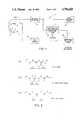
- FIG. 1is a block diagram of an arrhythmia detection system as part of an automatic implantable defibrillator/cardioverter.
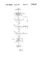
- FIG. 2is a schematic functional flow chart of the acceleration/deceleration detector logic of FIG. 1.
- FIG. 3is a graphical representation of a series of R-waves.
- the arrhythmia detecting system 1 of the present inventionis depicted schematically in FIG. 1.
- the arrhythmia detecting system 1is adapted to be coupled with electrodes 3 and 5, which are connected to the heart 7 of the patient.
- the electrodesinclude a bipolar sensing electrode 3, adapted to be located in the right ventricle for ECG sensing of ventricular contractions, and intracardiac sensing and high voltage delivery electrode 5 adapted to be located in the superior vena cava (SVC) for delivering the high-voltage defibrillating/cardioverting pulses.
- a patch electrode 6is connected to the myocardium of the heart, 7, or an additional electrode surface can be placed near electrodes 3 and 5.
- the bipolar electrode 3provides an ECG input signal to an R-wave detector circuit 9.
- the SVC electrode 5, acting with the patch electrode 6,provides the input to a PDF circuit 11.
- the R-wave detector circuit 9may be similar to that disclosed in U.S. Pat. No. 4,614,192 or that disclosed in U.S. Pat. No. 4,393,877. Basically, the R-wave detector circuit 9 detects the R-waves and provides uniform pulses proportional to the R-waves of the incoming ECG signal. The time between R-waves is inversely proportional to the rate of R-waves, or the heart rate.
- the PDF circuitmay be that described in U.S. Pat. Nos. 4,184,493 and 4,202,340.
- the R-wave detector circuit 9has its output coupled with a rate averaging circuit 13 which receives the detected R-waves, calculates the average heart rate, and provides an output when the average heart rate exceeds a predetermined value.
- the rate averaging circuitmay be that disclosed in U.S. Pat. No. 4,393,877 or U.S. Pat. No. 4,614,192 (see elements 80 and 36 of FIG. 2 of the U.S. Pat. No. 4,614,192.
- the outputs of the rate averaging circuit 13 and the PDF circuit 11are provided as inputs to an arrhythmia detector logic circuit 15.
- Such logic 15may include an AND gate, the inputs of which receive the outputs of the rate averaging circuit 13 and the PDF circuit 11 so as to provide an output to a pulse-generator (not shown) upon the concurrence of output signals from the PDF circuit 11 and the rate averaging circuit 13, as is known in the art.
- the detector logic 15includes a means for disabling the PDF circuit 11 output when it is desired to detect an arryhthmia solely upon the basis of high average heart rate from 13. The logic to disable the PDF circuit 11, and to detect arrhythmias solely on the basis of the rate averaging circuit 13, is described in U.S. Pat. No. 4,393,877.
- the novel heart rate acceleration/deceleration detecting system 17 of the present inventionis depicted schematically in FIG. 1.
- the acceleration/deceleration detecting logic 17is connected with the R-wave detector 9 to receive electrical pulses indicative of the heart rate. As set forth, these pulses are proportional to the R-waves that are detected from the ECG wave packet wherein the instanteous heart rate can be calculated, as is well-known in the art, by measuring the time interval between the detected R-waves. This time interval is inversely proportional to the instantaneous heart rate.
- the R-wave detector 9may itself include circuitry for converting the detected R-waves into instantaneous readings of the heart rate, and provide such heart rate information, in digital form, to the acceleration/deceleration detecting system 17.
- the acceleration/deceleration rate detecting system 17receives the R-wave pulses and determines the heart rate on a beat-by-beat basis. The system 17 determines if the heart rate is accelerating excessively, and performs other logic in a manner to be described. If an acceleration is determined, of the type that may require a defibrillating/cardioverting pulse, the acceleration/deceleration detecting system 17 provides an output signal to the arrhythmia detector logic circuit 15. Upon the occurrence of an output from the rate averaging circuit 13 and the acceleration/deceleration detector circuit 17, the arrhythmia detector logic provides an output to the pulse generator. Such a logic may be a simple AND gate.
- output signals from the PDF circuit 11, the rate averaging circuit 13 and the acceleration/deceleration detecting system 17are required for the detector logic 15 to trigger the pulse generator.
- Each of these signalsmay comprise inputs to an AND gate, or other logic.
- FIG. 2A functional flow chart of the acceleration/deceleration detecting operation is depicted in FIG. 2. It should be apparent to one of ordinary skill in the art that the flow chart functions may be configured in a hardwired logic circuit or in software by the use of a microprocessor which carries out the logical functions described in the functional flow chart. The actual configuration of the flow chart logic, either in hardware or in microprocessor-based firmware, would be relatively straightforward to one of ordinary skill.
- the acceleration/deceleration detecting system 17may include any conventional microprocessor having associated random access memory (RAM) and read-only memory (ROM) along with necessary data and address lines.
- the microprocessor systemreceives, as an input, the electrical signals reflecting the R-waves from the R-wave detector 9 and provides an output signal to the arrhythmia detector logic circuit 15, or may itself perform the arrhythmia logic functions.
- the series of heart beat, or R-wave, signals from the R-wave detector 9are read by the microprocessor and the heart rate is determined for a group of the series of R-waves, and stored in an appropriate memory location, such as in RAM (decision block 19).
- the heart rateis calculated for a group of two successive R-wave signals and then upon receipt of each successive R-wave.
- the heart ratemay be calculated for a larger number of R-waves signals, e.g., every three heart beats, a new heart rate is calculated.
- the instantaneous heart rateis determined by the microprocessor as each successive R-wave is detected and the successive heart rates are stored in memory. Initially, at least four distinct heart rates are calculated (requiring at least five R-waves) and stored in memory.
- each beat-to-beat rate (R n )is compared with the prior beat-to-beat rate (R n-1 ) to determine if it exceeds a predetermined value A as depicted in decision block 21. If the beat-to-beat heart rate (R n ) exceeds the prior beat-to-beat heart rate (R n-1 ) by a value greater than A, the system continues to decision block 23 in a manner to be described. For example, assume that the value A is 15, representing 15 beats per minute (bpm). If the heart rate (R n ) exceeds the prior heart rate (R n-1 ) by 15 bpm, an acceleration is determined and the system continues to decision block 23, to be described. If the increase in heart rate is less than 15 bpm, a negative (No) determination is made and the system returns and keeps checking until the heart rate has increased over the prior heart rate by the predetermined value A.
- the heart rate (R n )is compared with the next succeeding heart rate (R n +1) to determine if it exceeds the succeeding heart rate by a value greater than a predetermined value B. If such determination is affirmative (Yes) then a deceleration is determined and the system loops back to the beginning of decision block 21. That is, if an acceleration of the heart rate is immediately followed by a deceleration (a deceleration greater than the value B) an arrhythmic condition is not assumed and the system continues to monitor incoming heart rate. (Such determination indicates a PVC, discussed below.) If such excessive deceleration is not determined (No), the system continues to decision block 25.
- the value for Bcan be readily chosen depending on the sensitivity desired. For example, once the value for A is selected, one now knows where a premature beat would fall between two "normal" beats. The total time interval over three beats, from a normal beat to a premature beat to the next normal beat, is generally the same as the time interval over three normal beats. That is, at a "normal" rate of 60 bpm, the time interval over three beats is 2000 msec. If the value for A is 15, a PVC would then occur at 787 msec after the first beat (i.e., at 76 bpm), followed by the next beat 1213 msec later (i.e., at 49 bpm). Thus B, in this instance, would be at least equal to 26.
- the systemdetermines whether the acceleration was immediately preceded by a large deceleration. That is, the immediately preceding heart rate (R n-1 ) is compared with its immediately preceding heart rate (R n-2 ). If the second most preceding heart rate (R n-2 ) exceeds the immediately preceding heart rate (R n-1 ) by a value greater than the predetermined value B, then a large deceleration is assumed. If such occurs, as indicated by the "Yes" output of decision block 25, then an AGC dropout is assumed and the system loops back to continue to operate on subsequent heart rates. That is, if a large deceleration prior to a large acceleration were detected, no output from the acceleration detector 17 is provided. If a large deceleration is not determined (output "No" of block 25), the system continues to block 27.
- the systemprovides an output to the arrhythmia detector 15, as depicted by decision block 27.
- the output signalis maintained for a predetermined time period following the satisfaction of the conditions of blocks 21, 23 and 25. That is, if a large acceleration of the heart rate is detected, without the detection of a prior or subsequent large deceleration, an output signal or "true" signal, is provided to the arrhythmia detector 15 and maintained for a predetermined time period.
- the outputmay be provided to the detector 15 only after a predetermined number of the above-described arrhythmic conditions are satisfied in a given time period, or over a predetermined number of heart beats. That is, the output signal is provided from decision block 27 only if, for example, five acceleration/no deceleration conditions have occurred in a given time period or over a predetermined number of beats.
- FIG. 3is a graphical representation of three distinct series of heart beats, representing the output of the R-wave detector 9, to exemplify how the acceleration/deceleration detecting system 17 operates.
- waveform (a) of FIG. 3a heart rate of 70 bpm is determined from the first two R-waves, the next R-wave is detected at 70 bpm, the next R-wave is detected at 105 bpm, followed by an 140 bpm rate.
- an acceleration signalis determined (decision block 21). The system then checks to see if such acceleration was followed by a large deceleration (decision block 23).
- the waveform depictedshows the heart rate of increasing from 70 bpm to 140 bpm followed by a rate of 70 bpm.
- a large accelerationis immediately followed by a large deceleration. This is indicative of a premature ventricular contraction (PVC) and would result in no output provided to the arrhythmia detector logic 15.
- PVCpremature ventricular contraction
- the decision block 25may be omitted. That is, a signal would be provided to the arrhythma detector 15 if a large acceleration is detected followed by the absence of a large deceleration, ignoring whether a large deceleration preceded the detection of the large acceleration.
- a PVC output terminal 18is provided which may be connected with any conventional indicator, such as a visual display.
- any conventional indicatorsuch as a visual display.
Landscapes
- Health & Medical Sciences (AREA)
- Life Sciences & Earth Sciences (AREA)
- Cardiology (AREA)
- Engineering & Computer Science (AREA)
- Animal Behavior & Ethology (AREA)
- Public Health (AREA)
- Physiology (AREA)
- Biomedical Technology (AREA)
- Veterinary Medicine (AREA)
- Heart & Thoracic Surgery (AREA)
- Biophysics (AREA)
- General Health & Medical Sciences (AREA)
- Radiology & Medical Imaging (AREA)
- Nuclear Medicine, Radiotherapy & Molecular Imaging (AREA)
- Signal Processing (AREA)
- Physics & Mathematics (AREA)
- Pathology (AREA)
- Medical Informatics (AREA)
- Molecular Biology (AREA)
- Surgery (AREA)
- Measurement And Recording Of Electrical Phenomena And Electrical Characteristics Of The Living Body (AREA)
- Electrotherapy Devices (AREA)
- Measuring Pulse, Heart Rate, Blood Pressure Or Blood Flow (AREA)
Abstract
Description
Claims (5)
Priority Applications (7)
| Application Number | Priority Date | Filing Date | Title |
|---|---|---|---|
| US06/862,785US4796620A (en) | 1986-05-13 | 1986-05-13 | System for sensing abnormal heart activity by means of heart rate acceleration and deceleration detection |
| GB8710447AGB2190505B (en) | 1986-05-13 | 1987-05-01 | System for sensing abnormal heart activity by means of heart rate acceleration and deceleration detection |
| DE19873715823DE3715823A1 (en) | 1986-05-13 | 1987-05-12 | SYSTEM FOR DETECTING ABNORMAL HEART ACTIVITIES |
| JP62115730AJPS6335229A (en) | 1986-05-13 | 1987-05-12 | System for sensing abnormal activity of heart by detecting acceleration and deceleration of heart rate |
| NL8701140ANL191831C (en) | 1986-05-13 | 1987-05-13 | System for determining an abnormal cardiac activity. |
| FR878706740AFR2598920B1 (en) | 1986-05-13 | 1987-05-13 | SYSTEM FOR DETECTING ABNORMAL HEART ACTIVITY BY DETERMINING THE ACCELERATION AND DECELERATION OF THE HEART RATE |
| CA000537023ACA1304136C (en) | 1986-05-13 | 1987-05-13 | System for sensing abnormal heart activity by means of heart rate acceleration and deceleration detection |
Applications Claiming Priority (1)
| Application Number | Priority Date | Filing Date | Title |
|---|---|---|---|
| US06/862,785US4796620A (en) | 1986-05-13 | 1986-05-13 | System for sensing abnormal heart activity by means of heart rate acceleration and deceleration detection |
Publications (1)
| Publication Number | Publication Date |
|---|---|
| US4796620Atrue US4796620A (en) | 1989-01-10 |
Family
ID=25339346
Family Applications (1)
| Application Number | Title | Priority Date | Filing Date |
|---|---|---|---|
| US06/862,785Expired - LifetimeUS4796620A (en) | 1986-05-13 | 1986-05-13 | System for sensing abnormal heart activity by means of heart rate acceleration and deceleration detection |
Country Status (7)
| Country | Link |
|---|---|
| US (1) | US4796620A (en) |
| JP (1) | JPS6335229A (en) |
| CA (1) | CA1304136C (en) |
| DE (1) | DE3715823A1 (en) |
| FR (1) | FR2598920B1 (en) |
| GB (1) | GB2190505B (en) |
| NL (1) | NL191831C (en) |
Cited By (24)
| Publication number | Priority date | Publication date | Assignee | Title |
|---|---|---|---|---|
| US4901726A (en)* | 1988-01-29 | 1990-02-20 | Telectronics N.V. | Rate-responsive, distributed-rate pacemaker |
| US4919144A (en)* | 1988-02-26 | 1990-04-24 | First Medic | Defibrillator ECG interpreter |
| US4969465A (en)* | 1989-05-19 | 1990-11-13 | Ventritex, Inc. | Cardiac therapy method |
| US4971058A (en)* | 1989-07-06 | 1990-11-20 | Ventritex, Inc. | Cardiac therapy method with duration timer |
| US4974601A (en)* | 1988-09-05 | 1990-12-04 | University Of North Carolina At Charlotte | Portable heart monitor performing multiple functions |
| US5086772A (en)* | 1990-07-30 | 1992-02-11 | Telectronics Pacing Systems, Inc. | Arrhythmia control system employing arrhythmia recognition algorithm |
| US5184615A (en)* | 1991-03-08 | 1993-02-09 | Telectronics Pacing Systems, Inc. | Apparatus and method for detecting abnormal cardiac rhythms using evoked potential measurements in an arrhythmia control system |
| US5312443A (en)* | 1992-02-20 | 1994-05-17 | Angeion Corporation | Arrhythmia-detection criteria process for a cardioverter/defibrillator |
| US5391187A (en)* | 1994-02-22 | 1995-02-21 | Zmd Corporation | Semiautomatic defibrillator with heart rate alarm driven by shock advisory algorithm |
| US5423325A (en)* | 1993-03-12 | 1995-06-13 | Hewlett-Packard Corporation | Methods for enhancement of HRV and late potentials measurements |
| US5507778A (en)* | 1994-02-22 | 1996-04-16 | Zmd Corporation | Semiautomatic defibrillator with synchronized shock delivery |
| US5601611A (en)* | 1994-08-05 | 1997-02-11 | Ventritex, Inc. | Optical blood flow measurement apparatus and method and implantable defibrillator incorporating same |
| US5620471A (en)* | 1995-06-16 | 1997-04-15 | Pacesetter, Inc. | System and method for discriminating between atrial and ventricular arrhythmias and for applying cardiac therapy therefor |
| US5645570A (en)* | 1992-03-26 | 1997-07-08 | Sorin Biomedica S.P.A. | Method and device for monitoring and detecting sympatho-vagal activity and for providing therapy in response thereto |
| US5676686A (en)* | 1994-05-20 | 1997-10-14 | Medtronic, Inc. | Pacemaker with vasovagal syncope detection |
| US6263238B1 (en)* | 1998-04-16 | 2001-07-17 | Survivalink Corporation | Automatic external defibrillator having a ventricular fibrillation detector |
| WO2002036001A1 (en)* | 2000-11-02 | 2002-05-10 | Cardiac Pacemakers, Inc. | Lv ectopic density trending |
| WO2002087432A3 (en)* | 2001-04-30 | 2003-01-09 | Medtronic Inc | Method and system for monitoring heart failure using rate change dynamics |
| EP1062977A3 (en)* | 1999-06-23 | 2003-09-17 | BIOTRONIK Mess- und Therapiegeräte GmbH & Co Ingenieurbüro Berlin | Method of detecting intervals in cardiac signals within cardiological devices |
| US6671548B1 (en) | 1999-12-29 | 2003-12-30 | Pacesetter, Inc. | Implantable stimulation device and method for discrimination atrial and ventricular arrhythmias |
| US20050149444A1 (en)* | 1992-12-15 | 2005-07-07 | Jonathan Schull | Method for tracking software lineages |
| US9126055B2 (en) | 2012-04-20 | 2015-09-08 | Cardiac Science Corporation | AED faster time to shock method and device |
| US9289167B2 (en) | 1997-04-14 | 2016-03-22 | Masimo Corporation | Signal processing apparatus and method |
| EP3981326A4 (en)* | 2019-09-17 | 2022-07-27 | Honor Device Co., Ltd. | DATA DISPLAY METHOD AND ELECTRONIC DEVICE |
Families Citing this family (6)
| Publication number | Priority date | Publication date | Assignee | Title |
|---|---|---|---|---|
| WO1992005836A1 (en)* | 1990-10-04 | 1992-04-16 | Siemens-Elema Ab | Arrangement, in particular heart pacemaker, for recording a heart activity measurement parameter |
| EP0570895B1 (en)* | 1992-05-18 | 2003-12-03 | Cardiac Pacemakers, Inc. | System for event processing in biological applications |
| US6009349A (en)* | 1993-11-16 | 1999-12-28 | Pacesetter, Inc. | System and method for deriving hemodynamic signals from a cardiac wall motion sensor |
| DE19749393A1 (en)* | 1997-11-07 | 1999-05-20 | Georg Prof Dr Schmidt | Method and device for evaluating electrocardiograms in the area of extrasystoles |
| DE10048649A1 (en)* | 2000-09-26 | 2002-04-11 | Biotronik Mess & Therapieg | Risikomontoring |
| WO2015107266A1 (en)* | 2014-01-16 | 2015-07-23 | Aboa Legis Oy | Method and device for the detection of the degree of entropy of medical data |
Citations (15)
| Publication number | Priority date | Publication date | Assignee | Title |
|---|---|---|---|---|
| US3398736A (en)* | 1964-04-15 | 1968-08-27 | Brant | Apparatus for determining instantaneous acceleration of recurring bioregulatory events |
| US3618593A (en)* | 1968-09-02 | 1971-11-09 | Inst Technitcheska Kib Pri Ban | Method of and a system for the automatic analysis of heart disturbances |
| US3699949A (en)* | 1971-07-26 | 1972-10-24 | Human Factors Research Inc | Pulse jitter measurement especially for heart beat measurement |
| US3718827A (en)* | 1971-09-14 | 1973-02-27 | Us Army | Voltage-controlled one-shot |
| DE2331551A1 (en)* | 1972-07-13 | 1974-01-24 | Hoffmann La Roche | HEART RATE MONITOR |
| US3837333A (en)* | 1973-04-19 | 1974-09-24 | A Bruckheim | Heart surveillance device |
| DE2543713A1 (en)* | 1975-10-01 | 1977-04-07 | Keiper Trainingsysteme Gmbh | Heartbeat frequency measuring system - determines mean value from number of counting impulses during predetermined time |
| DE2717747A1 (en)* | 1976-05-19 | 1977-12-29 | Schmid Walter | HEART RATE MONITOR |
| DE2750646A1 (en)* | 1977-11-09 | 1979-05-10 | Herwig Frhr Von Di Nettelhorst | Heartbeat histogram registering and classifying system - includes counter with additional programmed fixed value plug in memory for classification |
| US4184493A (en)* | 1975-09-30 | 1980-01-22 | Mieczyslaw Mirowski | Circuit for monitoring a heart and for effecting cardioversion of a needy heart |
| US4202340A (en)* | 1975-09-30 | 1980-05-13 | Mieczyslaw Mirowski | Method and apparatus for monitoring heart activity, detecting abnormalities, and cardioverting a malfunctioning heart |
| DE3031576A1 (en)* | 1979-08-22 | 1981-03-26 | Warner-Lambert Co., Morris Plains, N.J. | HEART RATE ANALYZER |
| US4393877A (en)* | 1981-05-15 | 1983-07-19 | Mieczyslaw Mirowski | Heart rate detector |
| US4457315A (en)* | 1978-09-18 | 1984-07-03 | Arvin Bennish | Cardiac arrhythmia detection and recording |
| US4614192A (en)* | 1982-04-21 | 1986-09-30 | Mieczyslaw Mirowski | Implantable cardiac defibrillator employing bipolar sensing and telemetry means |
Family Cites Families (8)
| Publication number | Priority date | Publication date | Assignee | Title |
|---|---|---|---|---|
| US3633569A (en)* | 1969-01-28 | 1972-01-11 | James R Brayshaw | Arrhythmia counter |
| GB1486190A (en)* | 1973-12-15 | 1977-09-21 | Ferranti Ltd | Monitoring heart activity |
| DE2713747C2 (en)* | 1977-03-29 | 1979-05-23 | Robert Bosch Gmbh, 7000 Stuttgart | Washing installation, in particular for cover panes for motor vehicle lights |
| EP0008505B1 (en)* | 1978-08-22 | 1983-06-29 | Siemens-Elema AB | Apparatus for tachycardia investigation or control |
| US4384585A (en)* | 1981-03-06 | 1983-05-24 | Medtronic, Inc. | Synchronous intracardiac cardioverter |
| US4493325A (en)* | 1982-05-03 | 1985-01-15 | Medtronic, Inc. | Tachyarrhythmia pacer |
| US4436092A (en)* | 1982-05-19 | 1984-03-13 | Purdue Research Foundation | Exercise responsive cardiac pacemaker |
| US4548209A (en)* | 1984-02-06 | 1985-10-22 | Medtronic, Inc. | Energy converter for implantable cardioverter |
- 1986
- 1986-05-13USUS06/862,785patent/US4796620A/ennot_activeExpired - Lifetime
- 1987
- 1987-05-01GBGB8710447Apatent/GB2190505B/ennot_activeExpired - Lifetime
- 1987-05-12JPJP62115730Apatent/JPS6335229A/enactiveGranted
- 1987-05-12DEDE19873715823patent/DE3715823A1/enactiveGranted
- 1987-05-13NLNL8701140Apatent/NL191831C/ennot_activeIP Right Cessation
- 1987-05-13FRFR878706740Apatent/FR2598920B1/ennot_activeExpired - Lifetime
- 1987-05-13CACA000537023Apatent/CA1304136C/ennot_activeExpired - Lifetime
Patent Citations (15)
| Publication number | Priority date | Publication date | Assignee | Title |
|---|---|---|---|---|
| US3398736A (en)* | 1964-04-15 | 1968-08-27 | Brant | Apparatus for determining instantaneous acceleration of recurring bioregulatory events |
| US3618593A (en)* | 1968-09-02 | 1971-11-09 | Inst Technitcheska Kib Pri Ban | Method of and a system for the automatic analysis of heart disturbances |
| US3699949A (en)* | 1971-07-26 | 1972-10-24 | Human Factors Research Inc | Pulse jitter measurement especially for heart beat measurement |
| US3718827A (en)* | 1971-09-14 | 1973-02-27 | Us Army | Voltage-controlled one-shot |
| DE2331551A1 (en)* | 1972-07-13 | 1974-01-24 | Hoffmann La Roche | HEART RATE MONITOR |
| US3837333A (en)* | 1973-04-19 | 1974-09-24 | A Bruckheim | Heart surveillance device |
| US4184493A (en)* | 1975-09-30 | 1980-01-22 | Mieczyslaw Mirowski | Circuit for monitoring a heart and for effecting cardioversion of a needy heart |
| US4202340A (en)* | 1975-09-30 | 1980-05-13 | Mieczyslaw Mirowski | Method and apparatus for monitoring heart activity, detecting abnormalities, and cardioverting a malfunctioning heart |
| DE2543713A1 (en)* | 1975-10-01 | 1977-04-07 | Keiper Trainingsysteme Gmbh | Heartbeat frequency measuring system - determines mean value from number of counting impulses during predetermined time |
| DE2717747A1 (en)* | 1976-05-19 | 1977-12-29 | Schmid Walter | HEART RATE MONITOR |
| DE2750646A1 (en)* | 1977-11-09 | 1979-05-10 | Herwig Frhr Von Di Nettelhorst | Heartbeat histogram registering and classifying system - includes counter with additional programmed fixed value plug in memory for classification |
| US4457315A (en)* | 1978-09-18 | 1984-07-03 | Arvin Bennish | Cardiac arrhythmia detection and recording |
| DE3031576A1 (en)* | 1979-08-22 | 1981-03-26 | Warner-Lambert Co., Morris Plains, N.J. | HEART RATE ANALYZER |
| US4393877A (en)* | 1981-05-15 | 1983-07-19 | Mieczyslaw Mirowski | Heart rate detector |
| US4614192A (en)* | 1982-04-21 | 1986-09-30 | Mieczyslaw Mirowski | Implantable cardiac defibrillator employing bipolar sensing and telemetry means |
Cited By (26)
| Publication number | Priority date | Publication date | Assignee | Title |
|---|---|---|---|---|
| US4901726A (en)* | 1988-01-29 | 1990-02-20 | Telectronics N.V. | Rate-responsive, distributed-rate pacemaker |
| US4919144A (en)* | 1988-02-26 | 1990-04-24 | First Medic | Defibrillator ECG interpreter |
| US4974601A (en)* | 1988-09-05 | 1990-12-04 | University Of North Carolina At Charlotte | Portable heart monitor performing multiple functions |
| US4969465A (en)* | 1989-05-19 | 1990-11-13 | Ventritex, Inc. | Cardiac therapy method |
| US4971058A (en)* | 1989-07-06 | 1990-11-20 | Ventritex, Inc. | Cardiac therapy method with duration timer |
| US5086772A (en)* | 1990-07-30 | 1992-02-11 | Telectronics Pacing Systems, Inc. | Arrhythmia control system employing arrhythmia recognition algorithm |
| US5184615A (en)* | 1991-03-08 | 1993-02-09 | Telectronics Pacing Systems, Inc. | Apparatus and method for detecting abnormal cardiac rhythms using evoked potential measurements in an arrhythmia control system |
| US5312443A (en)* | 1992-02-20 | 1994-05-17 | Angeion Corporation | Arrhythmia-detection criteria process for a cardioverter/defibrillator |
| US5645570A (en)* | 1992-03-26 | 1997-07-08 | Sorin Biomedica S.P.A. | Method and device for monitoring and detecting sympatho-vagal activity and for providing therapy in response thereto |
| US20050149444A1 (en)* | 1992-12-15 | 2005-07-07 | Jonathan Schull | Method for tracking software lineages |
| US5423325A (en)* | 1993-03-12 | 1995-06-13 | Hewlett-Packard Corporation | Methods for enhancement of HRV and late potentials measurements |
| US5391187A (en)* | 1994-02-22 | 1995-02-21 | Zmd Corporation | Semiautomatic defibrillator with heart rate alarm driven by shock advisory algorithm |
| US5507778A (en)* | 1994-02-22 | 1996-04-16 | Zmd Corporation | Semiautomatic defibrillator with synchronized shock delivery |
| US5676686A (en)* | 1994-05-20 | 1997-10-14 | Medtronic, Inc. | Pacemaker with vasovagal syncope detection |
| US5601611A (en)* | 1994-08-05 | 1997-02-11 | Ventritex, Inc. | Optical blood flow measurement apparatus and method and implantable defibrillator incorporating same |
| US5620471A (en)* | 1995-06-16 | 1997-04-15 | Pacesetter, Inc. | System and method for discriminating between atrial and ventricular arrhythmias and for applying cardiac therapy therefor |
| US9289167B2 (en) | 1997-04-14 | 2016-03-22 | Masimo Corporation | Signal processing apparatus and method |
| US6263238B1 (en)* | 1998-04-16 | 2001-07-17 | Survivalink Corporation | Automatic external defibrillator having a ventricular fibrillation detector |
| EP1062977A3 (en)* | 1999-06-23 | 2003-09-17 | BIOTRONIK Mess- und Therapiegeräte GmbH & Co Ingenieurbüro Berlin | Method of detecting intervals in cardiac signals within cardiological devices |
| US6671548B1 (en) | 1999-12-29 | 2003-12-30 | Pacesetter, Inc. | Implantable stimulation device and method for discrimination atrial and ventricular arrhythmias |
| WO2002036001A1 (en)* | 2000-11-02 | 2002-05-10 | Cardiac Pacemakers, Inc. | Lv ectopic density trending |
| US6718197B1 (en)* | 2000-11-02 | 2004-04-06 | Cardiac Pacemakers, Inc. | LV ectopic density trending |
| WO2002087432A3 (en)* | 2001-04-30 | 2003-01-09 | Medtronic Inc | Method and system for monitoring heart failure using rate change dynamics |
| US6636762B2 (en) | 2001-04-30 | 2003-10-21 | Medtronic, Inc. | Method and system for monitoring heart failure using rate change dynamics |
| US9126055B2 (en) | 2012-04-20 | 2015-09-08 | Cardiac Science Corporation | AED faster time to shock method and device |
| EP3981326A4 (en)* | 2019-09-17 | 2022-07-27 | Honor Device Co., Ltd. | DATA DISPLAY METHOD AND ELECTRONIC DEVICE |
Also Published As
| Publication number | Publication date |
|---|---|
| GB8710447D0 (en) | 1987-06-03 |
| DE3715823A1 (en) | 1987-12-03 |
| DE3715823C2 (en) | 1993-02-25 |
| JPH0554976B2 (en) | 1993-08-13 |
| NL191831C (en) | 1996-09-03 |
| CA1304136C (en) | 1992-06-23 |
| NL191831B (en) | 1996-05-01 |
| GB2190505B (en) | 1990-03-07 |
| GB2190505A (en) | 1987-11-18 |
| FR2598920A1 (en) | 1987-11-27 |
| JPS6335229A (en) | 1988-02-15 |
| NL8701140A (en) | 1987-12-01 |
| FR2598920B1 (en) | 1990-07-06 |
Similar Documents
| Publication | Publication Date | Title |
|---|---|---|
| US4796620A (en) | System for sensing abnormal heart activity by means of heart rate acceleration and deceleration detection | |
| US5179945A (en) | Defibrillation/cardioversion system with multiple evaluation of heart condition prior to shock delivery | |
| US5730141A (en) | Tachyarrhythmia detection method | |
| US7474920B2 (en) | Method and apparatus for delaying a ventricular tachycardia therapy | |
| US7353060B2 (en) | Adaptive anti-tachycardia therapy apparatus and method | |
| US5425749A (en) | Preemptive cardioversion therapy in an implantable cardioverter defibrillator | |
| US8214038B2 (en) | Post-shock recovery monitoring for tachyarrhythmia discrimination | |
| US4475551A (en) | Arrhythmia detection and defibrillation system and method | |
| EP1551504B1 (en) | Device for determining a metric for non-sustained arrhythmic event | |
| US6230055B1 (en) | Method and apparatus for adaptive tachycardia and fibrillation discrimination | |
| EP1677673B1 (en) | Method and apparatus for detecting and discriminating arrhythmias | |
| US5117824A (en) | Apparatus for monitoring electrical physiologic signals | |
| EP0473002B1 (en) | System and method for determining the defibrillation threshold energy | |
| US6904319B2 (en) | Method and apparatus for inhibiting atrial tachyarrhythmia therapy | |
| US5951593A (en) | Apparatus for preventing atrial fibrillation using precursors | |
| JPH10127590A (en) | Improved tachyarrhythmia discriminating method and device | |
| US5492128A (en) | Intracardiac electrogram sensing in an arrhythmia control system | |
| EP0538996B1 (en) | Apparatus for controlling tachyarrhythmia confirmation in response to patient history | |
| US20050245975A1 (en) | Method and apparatus for controlling delivery of pacing pulses in response to increased ectopic frequency | |
| CA2066843C (en) | Non-committed defibrillation/cardioversion system | |
| HK1007694B (en) | System and method for determining the defibrillation threshold energy |
Legal Events
| Date | Code | Title | Description |
|---|---|---|---|
| AS | Assignment | Owner name:MIROWSKI, MIECZYSLAW 2405 VELVET VALLEY WAY, OWING Free format text:ASSIGNMENT OF ASSIGNORS INTEREST.;ASSIGNOR:IMRAN, MIR;REEL/FRAME:004555/0615 Effective date:19860513 | |
| STCF | Information on status: patent grant | Free format text:PATENTED CASE | |
| FEPP | Fee payment procedure | Free format text:PAYOR NUMBER ASSIGNED (ORIGINAL EVENT CODE: ASPN); ENTITY STATUS OF PATENT OWNER: LARGE ENTITY | |
| FPAY | Fee payment | Year of fee payment:4 | |
| FEPP | Fee payment procedure | Free format text:PAYER NUMBER DE-ASSIGNED (ORIGINAL EVENT CODE: RMPN); ENTITY STATUS OF PATENT OWNER: LARGE ENTITY Free format text:PAYOR NUMBER ASSIGNED (ORIGINAL EVENT CODE: ASPN); ENTITY STATUS OF PATENT OWNER: LARGE ENTITY | |
| FPAY | Fee payment | Year of fee payment:8 | |
| FEPP | Fee payment procedure | Free format text:PAYER NUMBER DE-ASSIGNED (ORIGINAL EVENT CODE: RMPN); ENTITY STATUS OF PATENT OWNER: LARGE ENTITY | |
| FEPP | Fee payment procedure | Free format text:PAYOR NUMBER ASSIGNED (ORIGINAL EVENT CODE: ASPN); ENTITY STATUS OF PATENT OWNER: LARGE ENTITY | |
| FPAY | Fee payment | Year of fee payment:12 | |
| AS | Assignment | Owner name:MIROWSKI FAMILY VENTURES L.L.C., DISTRICT OF COLUM Free format text:ASSIGNMENT OF ASSIGNORS INTEREST;ASSIGNOR:MIROWSKI, ANNA;REEL/FRAME:012551/0360 Effective date:20010901 |