US4796475A - Personal air sampling impactor - Google Patents
Personal air sampling impactorDownload PDFInfo
- Publication number
- US4796475A US4796475AUS07/067,106US6710687AUS4796475AUS 4796475 AUS4796475 AUS 4796475AUS 6710687 AUS6710687 AUS 6710687AUS 4796475 AUS4796475 AUS 4796475A
- Authority
- US
- United States
- Prior art keywords
- impactor
- housing
- chamber
- nozzle
- air
- Prior art date
- Legal status (The legal status is an assumption and is not a legal conclusion. Google has not performed a legal analysis and makes no representation as to the accuracy of the status listed.)
- Expired - Lifetime
Links
Images
Classifications
- G—PHYSICS
- G01—MEASURING; TESTING
- G01N—INVESTIGATING OR ANALYSING MATERIALS BY DETERMINING THEIR CHEMICAL OR PHYSICAL PROPERTIES
- G01N1/00—Sampling; Preparing specimens for investigation
- G01N1/02—Devices for withdrawing samples
- G01N1/22—Devices for withdrawing samples in the gaseous state
- G01N1/2202—Devices for withdrawing samples in the gaseous state involving separation of sample components during sampling
- G01N1/2208—Devices for withdrawing samples in the gaseous state involving separation of sample components during sampling with impactors
- G—PHYSICS
- G01—MEASURING; TESTING
- G01N—INVESTIGATING OR ANALYSING MATERIALS BY DETERMINING THEIR CHEMICAL OR PHYSICAL PROPERTIES
- G01N1/00—Sampling; Preparing specimens for investigation
- G01N1/02—Devices for withdrawing samples
- G01N1/22—Devices for withdrawing samples in the gaseous state
- G01N1/2202—Devices for withdrawing samples in the gaseous state involving separation of sample components during sampling
- G01N1/2205—Devices for withdrawing samples in the gaseous state involving separation of sample components during sampling with filters
- G—PHYSICS
- G01—MEASURING; TESTING
- G01N—INVESTIGATING OR ANALYSING MATERIALS BY DETERMINING THEIR CHEMICAL OR PHYSICAL PROPERTIES
- G01N1/00—Sampling; Preparing specimens for investigation
- G01N1/02—Devices for withdrawing samples
- G01N1/22—Devices for withdrawing samples in the gaseous state
- G01N1/24—Suction devices
- G—PHYSICS
- G01—MEASURING; TESTING
- G01N—INVESTIGATING OR ANALYSING MATERIALS BY DETERMINING THEIR CHEMICAL OR PHYSICAL PROPERTIES
- G01N1/00—Sampling; Preparing specimens for investigation
- G01N1/02—Devices for withdrawing samples
- G01N1/22—Devices for withdrawing samples in the gaseous state
- G01N1/2202—Devices for withdrawing samples in the gaseous state involving separation of sample components during sampling
- G01N2001/222—Other features
- G01N2001/2223—Other features aerosol sampling devices
Definitions
- the present inventionrelates to ambient air sampling impactors that are simple and compact, and capable of being worn by a person for air sampling.
- Impactorsused for sampling air to determine the quality of the air are well known. Impactors classify airborne particles by their aerodynamic diameter, which is the same particle property important in predicting the disposition of the particle in human airways.
- the most standard design for an impactoris to have a jet of particle-laden air impinging upon an impaction plate, so that particles with high enough inertia will impact upon the plate and be separated from the air stream, and those which are small may be carried through one or more additional stages in a cascade impactor, or may be immediately passed through a filter where they are collected. If several impactor stages are used, and the particles collected at each stage are analyzed, information on the size distribution of the particles in the air is obtained. It is also a fairly common to have just a single stage impactor where the particles larger than a cutoff size are separated out, and the smaller particles are collected on a filter.
- Personal air samplersare worn on the body of an individual.
- An air pumpis also carried by the individual, for example, on a belt.
- These samplersare sometimes cyclones, such as the prior art Dore-Oliver Cyclone, and in some instances impactors have been used for personal sampling as well.
- a single stage impactor followed by a filteris the most convenient because it is much lighter than a conventional cascade impactor and, of course, since the instrument is to be worn by an individual, both the weight and compactness of the instrument have to be considered.
- the present inventionrelates to a personal air sampling impactor of a light weight and compact design, whether used as a single stage sampler or as a multistage, cascade sampler.
- the commonly known nozzle and impaction plate relationshipis utilized with an outlet filter.
- the housing for the filteris made integral with the impaction plate support for lighter weight and more compactness. After the air impinges upon the impaction plate in the present invention, the air flows around the impaction plate and filter support, and the particles not collected on the impaction plate are removed in the filter on the back side of the impaction plate.
- the impaction plate and filter holderare in one unit, and thus it can be rather thin in relation to its diameter or cross-dimension, lending itself easily to personal impactor use.
- a ringsupports the housing which holds the impaction plate and filter.
- the ringforms an outer housing covered with end caps that are held frictionally in place with O-rings and which can be removed for servicing.
- the airis drawn out of the outer housing to provide the necessary flow through the sampler.
- the pump for providing the air flowis supported by the individual and can be driven with power from a battery pack.
- the cascade impactors shown as variations of the present inventionalso use the basic configuration impaction plate and filter and have additional plates supported so that the size is reduced and the air flow path reverses direction.
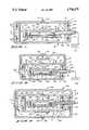
- FIG. 1is a sectional view through a personal sampling impactor made according to the present invention
- FIG. 2is a sectional view showing an additional impactor stage added to the personal sampling impactor of FIG. 1;
- FIG. 3is a further modified form of the invention showing a different type of a cascade impactor utilizing the device shown in FIG. 1 in an outer housing.
- a personal sampling impactor assemblyindicated generally at 10, comprises a housing ring 11 that is annular as shown, and which can be of relatively small size.
- the ring 11defines an interior chamber 12.
- the ringis covered with a first front cover 13 and a second rear cover 14 that have annular side flanges or walls 13A and 14A surrounding the ring 11 and which are held in place against an annular central rim 17 on the ring 11.
- Suitable O-rings 18 and 19are provided on the exterior of ring 11, and retain the covers 13 and 14 in place.
- the cover walls 13A and 14Ahave annular lips or ribs that ride over the O-rings and snap in place to hold the covers.
- the coverscan be removed by using a coin or small pry to lift the covers from the rim 17.
- Each of the covers 13 and 14can have a slot at the edge of its respective wall 13A and 14A for inserting the coin for twisting to remove the covers if desired.
- the cover 13has an end wall with an inlet orifice or nozzle 20 through which air flow indicated by the arrows 21 can pass.
- An impactor plate assembly indicated generally at 23 made according to the present inventionis supported on the interior chamber 12 through the use of a rigid flow tube 24 that is fixed to the ring 11 and the rim 17 thereof with a ferrule 24A.
- the flow tubeextends out from ring 11 a desired amount.
- the outer end of tube 24is connected to a suitable air pump 25.
- the pumpcan be supported on a person carrying the impactor.
- the impaction plate assembly 23includes an impaction plate 27 that is supported in a plate housing 28.
- the housing 28is circular in plan view (or it could be other outer configurations if desired), and has an internal cavity indicated at 29 formed therein on an opposite side from the impaction plate 27.
- the housing 28is relatively flat and is smaller in diameter than ring 11.
- the flow tube 24opens through a passageway 33 to the cavity 29.
- the outer opening to the cavity 29is covered with a filter 34 that is held in place with a suitable ring 35 that can be fastened with set screws 36 to the housing 28.
- the orifice or nozzle 20is selected in size for the flow desired and, once the pump 25 is operated, the flow indicated by arrows 21 will enter through the nozzle 20 and will impinge upon the impaction plate 27 as indicated by the arrows 39 and, of course, the flow will also diverge as indicated by the arrows 38 and will pass around the housing 28 within the chamber 12 and change direction to pass through the filter 34 and then out through the tube 24 to the pump 25.
- the front and rear covers 13 and 14are nearly identical in design, except that the front cover 13 has nozzle or orifice 20 formed in it. Both covers snap into place over the O-rings 18 and 19 so that they are tightly held, and sealed, but yet are removable. The front cover is removed for cleaning the impaction plate 27, and the rear cover 14 is removed to remove the filter and the filter holder.
- the parts, that is, the housing 28, ring 11 and covers 13 and 14can be made of metal, or can be a suitable plastic.
- the cutoff size of the particles carried around and through filter 34is selected in a normal manner. When done sampling air, the particles collected on the filter can be analyzed, as can the particles collected by impaction plate 27.
- FIG. 2A modified form of the invention is shown in FIG. 2, wherein the personal sampling device 10 is substantially identically constructed, but it is made into a cascade impactor by adding an additional cover having an inlet orifice or nozzle.
- the only change that needs to be made (in the impactor device 10) for the cascade impactor of FIG. 2is that the rim 17 is radially extended as shown at 17A, and the ferrule or sleeve shown at 60 to support the flow tube 24 is extended.
- a cup shaped outer cover 61is placed over the front cover 13 and can be held in place with friction fittings or with a screw or even with an O-ring, as shown for holding covers 13 and 14 in place, and the cover 61 carries an impaction plate 62 fixed to the interior thereof.
- the impaction plate 62is supported on the cover in a desired manner, and spans across the cover 61 (from one side to the other), so that it aligns with the inlet orifice 20.
- the cover 61has an inlet orifice or nozzle 63 defined therein that is a selected larger size then the orifice 20, and which is aligned with an impaction plate 62, so that incoming air impinges on the impaction plate 62 after it flows through the orifice 63, as shown by the arrows 64. The air will then flow around the impaction plate 62 as shown by the arrows 65 and enter the orifice 20. The subsequent flow is then as described in relation to FIG. 1 and is shown by the arrows 38, up through the filter 34 and out the flow tube 24 to the pump 25. Two stage cascade impaction thus is achieved in a very compact unit.
- the axial height(perpendicular to the plane of the impaction plates) is substantially less than the diameter of the housings.
- FIG. 3a further modified form of the invention is shown, and comprises a cascade personal impactor 70.
- the impactor 10is mounted in impactor 70 and is again identically constructed to the first form of the invention, and bears like numbers.
- the cascade impactor 70comprises a second outer ring 71 that surrounds the personal impactor 10 of the first form of the invention, and the ring 71 is mounted onto an outwardly extending portion of the flow tube 24 to be held in place concentric with the personal impactor 10.
- the flow tube 24can be inserted in any desired manner, or could be placed through a slot in the ring 71 and clamped in place.
- the ring 71also has an annular rim 71A.
- the ring 71carries O-rings 72 and 73 on its outer periphery.
- An outer cup-shaped cover 74is snapped over the ring 71 and retained in place with the O-ring 72.
- the cover 74has a small internal rib adjacent its outer edges, so that they are held sealed and retained in place.
- the cover 74is a cup shaped cover that is totally closed.
- a second cover 78is also cup shaped, and fits over the ring 71 and is held in place with the O-ring 73.
- the end wall of cover 78has an inlet orifice or nozzle 80 therein, which aligns with an impaction plate 82 that is mounted on the outer surface of the rear cover 14 of the personal sampling impactor 10.
- the impaction plate 82is aligned with the orifice 80, and air inflow through orifice 80 as shown by the arrow 84 will impinge against the impaction plate 82 to cause separation of particles.
- the orifice 80is of larger size than the orifice 20. The air flows through the interior chamber 85 that is formed by the covers 74 and 78 and the ring 71.
- the airflows between the inner periphery of ring 71 and the outer periphery of the personal impactor 10, and then flows into the orifice 20 where it impinges against impaction plate 27 as previously shown and explained.
- the flowgoes through the filter 34 and flow tube 24 to a pump such as pump 25.
- nozzles or orificesinstead of the single inlet nozzles shown.
- the nozzles or orificescan be rectangular instead of round, or if a higher flow rate is desired, the impactor can be somewhat larger.
- the unitis generally pancake shaped. Because the basic personal impactor 10 has the filter and housing for supporting the impactor plate as one unit, with an interior chamber that provides for air flow through a rigid flow tube, the size is kept small.
- the flow chambersare formed with a generally flat ring that surrounds the interior housing.
- the assemblyis small sized and very convenient to wear because it is light weight. Even the cascade type devices retain compactness, a generally "pancake” form, and they maintain a light construction.
- the covers that are showncan be snapped off as desired for cleaning and servicing, and the covers are easily made. The design is enclosed, and thus the particles are collected with very few losses, which is desirable.
Landscapes
- Health & Medical Sciences (AREA)
- Life Sciences & Earth Sciences (AREA)
- Engineering & Computer Science (AREA)
- Biomedical Technology (AREA)
- Molecular Biology (AREA)
- Physics & Mathematics (AREA)
- Chemical & Material Sciences (AREA)
- Analytical Chemistry (AREA)
- Biochemistry (AREA)
- General Health & Medical Sciences (AREA)
- General Physics & Mathematics (AREA)
- Immunology (AREA)
- Pathology (AREA)
- Sampling And Sample Adjustment (AREA)
Abstract
Description
Claims (8)
Priority Applications (1)
| Application Number | Priority Date | Filing Date | Title |
|---|---|---|---|
| US07/067,106US4796475A (en) | 1987-06-25 | 1987-06-25 | Personal air sampling impactor |
Applications Claiming Priority (1)
| Application Number | Priority Date | Filing Date | Title |
|---|---|---|---|
| US07/067,106US4796475A (en) | 1987-06-25 | 1987-06-25 | Personal air sampling impactor |
Publications (1)
| Publication Number | Publication Date |
|---|---|
| US4796475Atrue US4796475A (en) | 1989-01-10 |
Family
ID=22073739
Family Applications (1)
| Application Number | Title | Priority Date | Filing Date |
|---|---|---|---|
| US07/067,106Expired - LifetimeUS4796475A (en) | 1987-06-25 | 1987-06-25 | Personal air sampling impactor |
Country Status (1)
| Country | Link |
|---|---|
| US (1) | US4796475A (en) |
Cited By (34)
| Publication number | Priority date | Publication date | Assignee | Title |
|---|---|---|---|---|
| US4941899A (en)* | 1989-04-24 | 1990-07-17 | Regents Of The University Of Minnesota | Cyclone personal sampler for aerosols |
| US4942774A (en)* | 1989-03-20 | 1990-07-24 | The Texas A & M University System | Anisokinetic shrouded aerosol sampling probe |
| USD316865S (en) | 1988-07-28 | 1991-05-14 | E. I. Du Pont De Nemours And Company | Air pump |
| US5128539A (en)* | 1990-08-15 | 1992-07-07 | The United States Of America As Represented By The United States Department Of Energy | Apparatus having reduced background for measuring radiation activity in aerosol particles |
| US5412975A (en)* | 1993-11-12 | 1995-05-09 | The Regents Of The University Of California | Universal inlet for airborne-particle size-selective sampling |
| US5783756A (en)* | 1995-12-08 | 1998-07-21 | New York University | Portable sampler for volatile aerosols |
| US6435043B1 (en) | 1999-03-31 | 2002-08-20 | President And Fellows Of Harvard College | Impaction substrate and methods of use |
| US6463814B1 (en)* | 1999-11-05 | 2002-10-15 | Graftech | Bioaerosol slit impaction sampling device |
| US6517593B1 (en) | 2000-08-21 | 2003-02-11 | Larry Don Robertson | MBI vortex bioaerosol cassette insert |
| US20030066428A1 (en)* | 2001-10-08 | 2003-04-10 | Christoph Lindstrom | Water separator for a gas analyzer |
| US6632271B2 (en)* | 2000-08-21 | 2003-10-14 | Larry Don Robertson | MBI bioaerosol vortex cassette |
| US6685759B2 (en) | 2000-09-25 | 2004-02-03 | Southern Research Institute | Cascade impactor and jet plate for same |
| US6692553B2 (en)* | 2001-10-10 | 2004-02-17 | Environmental Monitoring Systems, Inc. | Particle collection apparatus and method |
| US20050084893A1 (en)* | 2003-10-16 | 2005-04-21 | Smiths Detection Inc. | Automated bioaerosol analysis platform |
| US20070062257A1 (en)* | 2005-09-20 | 2007-03-22 | Varian S.P.A. | Device and method for detecting the presence of test gas |
| US20070107495A1 (en)* | 2005-11-14 | 2007-05-17 | Dong-Hyun Kim | Particle adsorption chamber, sampling apparatus having a particle adsorption chamber, and sampling method using the same |
| US20070269349A1 (en)* | 2006-05-19 | 2007-11-22 | Institute Of Occupational Safety And Health, Council Of Labor Affairs | Three-stage dust sampler |
| US7334453B2 (en) | 2005-08-26 | 2008-02-26 | Skc, Inc. | Modular particulate sampler |
| US7651543B1 (en)* | 2006-06-26 | 2010-01-26 | The United States Of America As Represented By The Secretary Of The Navy | Omni-directional inlet for particulate collection |
| US20100187142A1 (en)* | 2006-03-27 | 2010-07-29 | Lee Jeong-Min | Cap assembly having storage chamber for secondary material with movable working member |
| US20100229657A1 (en)* | 2009-03-12 | 2010-09-16 | Weinstein Jason P | Sinter-bonded metal flow restrictor for regulating volumetric gas flow through an aerosol sampler inlet |
| US20100242633A1 (en)* | 2009-03-23 | 2010-09-30 | The President And Fellows Of Harvard University | Biological Particle Collector, and Methods of Use Thereof |
| EP2216638A3 (en)* | 2009-02-10 | 2012-03-14 | General Electric Company | Probe for removal of particulates from gas sampling stream |
| US20130220034A1 (en)* | 2012-02-16 | 2013-08-29 | University Of Iowa Research Foundation | Personal nanoparticle respiratory depositions sampler and methods of using the same |
| US20170102297A1 (en)* | 2014-06-04 | 2017-04-13 | Commissariat A L'energie Atomique Et Aux Energies Alternatives | Device for picking and transporting nanoobjects contained in aerosols, with a cassette with a module suited to reducing the suction noise during picking |
| CN106932244A (en)* | 2017-04-21 | 2017-07-07 | 苏州尚科洁净技术有限公司 | A kind of buffer of the big flow ram for air sampling |
| US9709541B2 (en) | 2011-10-26 | 2017-07-18 | Research Triangle Institute | Gas processing device with noise dampening |
| US20170370809A1 (en)* | 2016-06-23 | 2017-12-28 | Colorado State University Research Foundation | Portable air sampling device |
| US20200245899A1 (en)* | 2019-01-31 | 2020-08-06 | Hound Labs, Inc. | Mechanical Breath Collection Device |
| US11346753B2 (en)* | 2017-09-12 | 2022-05-31 | University Of Northumbria At Newcastle | Impactor for aerosol component collection |
| US11806711B1 (en) | 2021-01-12 | 2023-11-07 | Hound Labs, Inc. | Systems, devices, and methods for fluidic processing of biological or chemical samples using flexible fluidic circuits |
| US11874286B1 (en) | 2016-05-16 | 2024-01-16 | Hound Labs, Inc. | System and method for target substance identification |
| US11933731B1 (en) | 2020-05-13 | 2024-03-19 | Hound Labs, Inc. | Systems and methods using Surface-Enhanced Raman Spectroscopy for detecting tetrahydrocannabinol |
| US11977086B2 (en) | 2019-03-21 | 2024-05-07 | Hound Labs, Inc. | Biomarker detection from breath samples |
Citations (6)
| Publication number | Priority date | Publication date | Assignee | Title |
|---|---|---|---|---|
| DE427468C (en)* | 1924-11-15 | 1926-04-09 | Gustav Schuermann | Device for cleaning and drying steam or air with baffle plates in a housing |
| US3693457A (en)* | 1971-02-24 | 1972-09-26 | Battelle Development Corp | Source test cascade impactor |
| US3949594A (en)* | 1974-09-25 | 1976-04-13 | The United States Of America As Represented By The Secretary Of Interior | Two-stage disposable particle sampling head |
| US3957469A (en)* | 1975-02-03 | 1976-05-18 | Mine Safety Appliances Company | Filter cassette with removable capsule |
| US3966439A (en)* | 1974-11-11 | 1976-06-29 | Vennos Spyros Lysander N | Fluid sampling device |
| US4321822A (en)* | 1980-06-05 | 1982-03-30 | The Regents Of The University Of Minnesota | Impactor apparatus |
- 1987
- 1987-06-25USUS07/067,106patent/US4796475A/ennot_activeExpired - Lifetime
Patent Citations (6)
| Publication number | Priority date | Publication date | Assignee | Title |
|---|---|---|---|---|
| DE427468C (en)* | 1924-11-15 | 1926-04-09 | Gustav Schuermann | Device for cleaning and drying steam or air with baffle plates in a housing |
| US3693457A (en)* | 1971-02-24 | 1972-09-26 | Battelle Development Corp | Source test cascade impactor |
| US3949594A (en)* | 1974-09-25 | 1976-04-13 | The United States Of America As Represented By The Secretary Of Interior | Two-stage disposable particle sampling head |
| US3966439A (en)* | 1974-11-11 | 1976-06-29 | Vennos Spyros Lysander N | Fluid sampling device |
| US3957469A (en)* | 1975-02-03 | 1976-05-18 | Mine Safety Appliances Company | Filter cassette with removable capsule |
| US4321822A (en)* | 1980-06-05 | 1982-03-30 | The Regents Of The University Of Minnesota | Impactor apparatus |
Cited By (51)
| Publication number | Priority date | Publication date | Assignee | Title |
|---|---|---|---|---|
| USD316865S (en) | 1988-07-28 | 1991-05-14 | E. I. Du Pont De Nemours And Company | Air pump |
| US4942774A (en)* | 1989-03-20 | 1990-07-24 | The Texas A & M University System | Anisokinetic shrouded aerosol sampling probe |
| US4941899A (en)* | 1989-04-24 | 1990-07-17 | Regents Of The University Of Minnesota | Cyclone personal sampler for aerosols |
| US5128539A (en)* | 1990-08-15 | 1992-07-07 | The United States Of America As Represented By The United States Department Of Energy | Apparatus having reduced background for measuring radiation activity in aerosol particles |
| EP0473015A3 (en)* | 1990-08-15 | 1993-01-27 | U.S. Department Of Energy | Apparatus having reduced background for measuring radiation activity in aerosol particles |
| US5412975A (en)* | 1993-11-12 | 1995-05-09 | The Regents Of The University Of California | Universal inlet for airborne-particle size-selective sampling |
| US5783756A (en)* | 1995-12-08 | 1998-07-21 | New York University | Portable sampler for volatile aerosols |
| US6435043B1 (en) | 1999-03-31 | 2002-08-20 | President And Fellows Of Harvard College | Impaction substrate and methods of use |
| US6463814B1 (en)* | 1999-11-05 | 2002-10-15 | Graftech | Bioaerosol slit impaction sampling device |
| US7051605B2 (en)* | 1999-11-05 | 2006-05-30 | Environmental Monitoring Systems, Inc. | Bioaerosol slit impaction sampling device |
| US6517593B1 (en) | 2000-08-21 | 2003-02-11 | Larry Don Robertson | MBI vortex bioaerosol cassette insert |
| US6632271B2 (en)* | 2000-08-21 | 2003-10-14 | Larry Don Robertson | MBI bioaerosol vortex cassette |
| US6685759B2 (en) | 2000-09-25 | 2004-02-03 | Southern Research Institute | Cascade impactor and jet plate for same |
| US20030066428A1 (en)* | 2001-10-08 | 2003-04-10 | Christoph Lindstrom | Water separator for a gas analyzer |
| US6773493B2 (en)* | 2001-10-08 | 2004-08-10 | Instrumentarium Corp. | Water separator for a gas analyzer |
| US20040107837A1 (en)* | 2001-10-10 | 2004-06-10 | Jordan John L. | Particle collection apparatus and method |
| US6692553B2 (en)* | 2001-10-10 | 2004-02-17 | Environmental Monitoring Systems, Inc. | Particle collection apparatus and method |
| US20060185520A1 (en)* | 2001-10-10 | 2006-08-24 | Jordan John L Sr | Particle collection apparatus and method |
| US7135060B2 (en) | 2001-10-10 | 2006-11-14 | Enviromental Monitoring Systems, Inc. | Particle collection apparatus and method |
| US7785408B2 (en)* | 2001-10-10 | 2010-08-31 | Environmental Monitoring Systems, Inc. | Particle collection apparatus and method |
| US20080229930A1 (en)* | 2001-10-10 | 2008-09-25 | Jordan John L | Particle collection apparatus and method |
| US20050084893A1 (en)* | 2003-10-16 | 2005-04-21 | Smiths Detection Inc. | Automated bioaerosol analysis platform |
| US7334453B2 (en) | 2005-08-26 | 2008-02-26 | Skc, Inc. | Modular particulate sampler |
| US7597013B2 (en)* | 2005-09-20 | 2009-10-06 | Varian, S.P.A. | Device and method for detecting the presence of test gas |
| US20070062257A1 (en)* | 2005-09-20 | 2007-03-22 | Varian S.P.A. | Device and method for detecting the presence of test gas |
| US20070107495A1 (en)* | 2005-11-14 | 2007-05-17 | Dong-Hyun Kim | Particle adsorption chamber, sampling apparatus having a particle adsorption chamber, and sampling method using the same |
| US20100187142A1 (en)* | 2006-03-27 | 2010-07-29 | Lee Jeong-Min | Cap assembly having storage chamber for secondary material with movable working member |
| US7458284B2 (en)* | 2006-05-19 | 2008-12-02 | Institute Of Occupational Safety And Health, Council Of Labor Affairs | Three-stage dust sampler |
| US20070269349A1 (en)* | 2006-05-19 | 2007-11-22 | Institute Of Occupational Safety And Health, Council Of Labor Affairs | Three-stage dust sampler |
| US7651543B1 (en)* | 2006-06-26 | 2010-01-26 | The United States Of America As Represented By The Secretary Of The Navy | Omni-directional inlet for particulate collection |
| EP2216638A3 (en)* | 2009-02-10 | 2012-03-14 | General Electric Company | Probe for removal of particulates from gas sampling stream |
| US20100229657A1 (en)* | 2009-03-12 | 2010-09-16 | Weinstein Jason P | Sinter-bonded metal flow restrictor for regulating volumetric gas flow through an aerosol sampler inlet |
| US20100242633A1 (en)* | 2009-03-23 | 2010-09-30 | The President And Fellows Of Harvard University | Biological Particle Collector, and Methods of Use Thereof |
| US8250903B2 (en) | 2009-03-23 | 2012-08-28 | President And Fellows Of Harvard College | Biological particle collector and method for collecting biological particles |
| US9709541B2 (en) | 2011-10-26 | 2017-07-18 | Research Triangle Institute | Gas processing device with noise dampening |
| US20130220034A1 (en)* | 2012-02-16 | 2013-08-29 | University Of Iowa Research Foundation | Personal nanoparticle respiratory depositions sampler and methods of using the same |
| US9506843B2 (en)* | 2012-02-16 | 2016-11-29 | University Of Iowa Research Foundation | Personal nanoparticle respiratory depositions sampler and methods of using the same |
| US20170102297A1 (en)* | 2014-06-04 | 2017-04-13 | Commissariat A L'energie Atomique Et Aux Energies Alternatives | Device for picking and transporting nanoobjects contained in aerosols, with a cassette with a module suited to reducing the suction noise during picking |
| US10401263B2 (en)* | 2014-06-04 | 2019-09-03 | Commissariat A L'energie Atomique Et Aux Energies Alternatives | Device for picking and transporting nanoobjects contained in aerosols, with a cassette with a module suited to reducing the suction noise during picking |
| US11874286B1 (en) | 2016-05-16 | 2024-01-16 | Hound Labs, Inc. | System and method for target substance identification |
| US11360002B2 (en) | 2016-06-23 | 2022-06-14 | Colorado State University Research Foundation | Portable air sampling device |
| US10488305B2 (en)* | 2016-06-23 | 2019-11-26 | Colorado State University Research Foundation | Portable air sampling device |
| US20170370809A1 (en)* | 2016-06-23 | 2017-12-28 | Colorado State University Research Foundation | Portable air sampling device |
| CN106932244B (en)* | 2017-04-21 | 2023-04-18 | 苏州尚科洁净技术有限公司 | Buffer of large-flow impactor for air sampling |
| CN106932244A (en)* | 2017-04-21 | 2017-07-07 | 苏州尚科洁净技术有限公司 | A kind of buffer of the big flow ram for air sampling |
| US11346753B2 (en)* | 2017-09-12 | 2022-05-31 | University Of Northumbria At Newcastle | Impactor for aerosol component collection |
| US20200245899A1 (en)* | 2019-01-31 | 2020-08-06 | Hound Labs, Inc. | Mechanical Breath Collection Device |
| US11821821B1 (en) | 2019-01-31 | 2023-11-21 | Hound Labs, Inc. | Noninvasive point of care biomarker detection from breath samples |
| US11977086B2 (en) | 2019-03-21 | 2024-05-07 | Hound Labs, Inc. | Biomarker detection from breath samples |
| US11933731B1 (en) | 2020-05-13 | 2024-03-19 | Hound Labs, Inc. | Systems and methods using Surface-Enhanced Raman Spectroscopy for detecting tetrahydrocannabinol |
| US11806711B1 (en) | 2021-01-12 | 2023-11-07 | Hound Labs, Inc. | Systems, devices, and methods for fluidic processing of biological or chemical samples using flexible fluidic circuits |
Similar Documents
| Publication | Publication Date | Title |
|---|---|---|
| US4796475A (en) | Personal air sampling impactor | |
| US4972957A (en) | Particle concentrating sampler | |
| US4827779A (en) | Cartridge personal sampling impactor | |
| US3983743A (en) | Apparatus and method for the analysis of a particle-laden gas | |
| US6664550B2 (en) | Apparatus to collect, classify, concentrate, and characterize gas-borne particles | |
| US4670135A (en) | High volume virtual impactor | |
| US5040424A (en) | High volume PM10 sampling inlet | |
| US3949594A (en) | Two-stage disposable particle sampling head | |
| US5858043A (en) | Virtual impactors with slit shaped nozzles without slit ends | |
| US8205511B1 (en) | Air-sampling device and method of use | |
| US4178794A (en) | Environmental sampling device | |
| US3741001A (en) | Apparatus for sampling particulates in gases | |
| US5498271A (en) | Diesel particle virtual impactor sampler | |
| EP0352126A2 (en) | An inlet for a high volume particle sampler | |
| CA2650784C (en) | Particle collection apparatus and method | |
| US6125845A (en) | Respirator fit-testing with size selected aerosol | |
| US7334453B2 (en) | Modular particulate sampler | |
| CN112639433B (en) | Measurement system for researching concentrated aerosol particles in gas phase | |
| US6472203B1 (en) | Combination air sampling cassette and nutrient media dish | |
| US20050279181A1 (en) | Air sampler with parallel impactors | |
| US20070269349A1 (en) | Three-stage dust sampler | |
| US4274846A (en) | Particle sizing sampler | |
| US7082811B2 (en) | Cascade impactor with individually driven impactor plates | |
| EP0237245A3 (en) | Spectrometertest gas chamber | |
| US5343767A (en) | Low particle loss cascade impactor |
Legal Events
| Date | Code | Title | Description |
|---|---|---|---|
| AS | Assignment | Owner name:REGENTS OF THE UNIVERISTY OF MINNESOTA, MINNEAPOLI Free format text:ASSIGNMENT OF ASSIGNORS INTEREST.;ASSIGNOR:MARPLE, VIRGIL A.;REEL/FRAME:004729/0946 Effective date:19870616 Owner name:REGENTS OF THE UNIVERISTY OF MINNESOTA, A CORP. OF Free format text:ASSIGNMENT OF ASSIGNORS INTEREST;ASSIGNOR:MARPLE, VIRGIL A.;REEL/FRAME:004729/0946 Effective date:19870616 | |
| STCF | Information on status: patent grant | Free format text:PATENTED CASE | |
| CC | Certificate of correction | ||
| CC | Certificate of correction | ||
| FEPP | Fee payment procedure | Free format text:PAYOR NUMBER ASSIGNED (ORIGINAL EVENT CODE: ASPN); ENTITY STATUS OF PATENT OWNER: SMALL ENTITY | |
| FEPP | Fee payment procedure | Free format text:PAYER NUMBER DE-ASSIGNED (ORIGINAL EVENT CODE: RMPN); ENTITY STATUS OF PATENT OWNER: SMALL ENTITY Free format text:PAYOR NUMBER ASSIGNED (ORIGINAL EVENT CODE: ASPN); ENTITY STATUS OF PATENT OWNER: SMALL ENTITY | |
| FEPP | Fee payment procedure | Free format text:PAYOR NUMBER ASSIGNED (ORIGINAL EVENT CODE: ASPN); ENTITY STATUS OF PATENT OWNER: SMALL ENTITY Free format text:PAYER NUMBER DE-ASSIGNED (ORIGINAL EVENT CODE: RMPN); ENTITY STATUS OF PATENT OWNER: SMALL ENTITY | |
| FPAY | Fee payment | Year of fee payment:4 | |
| FPAY | Fee payment | Year of fee payment:8 | |
| FPAY | Fee payment | Year of fee payment:12 |