US4796247A - Compact disc (CD) player and method of compensating for tracking jumps - Google Patents
Compact disc (CD) player and method of compensating for tracking jumpsDownload PDFInfo
- Publication number
- US4796247A US4796247AUS07/054,688US5468887AUS4796247AUS 4796247 AUS4796247 AUS 4796247AUS 5468887 AUS5468887 AUS 5468887AUS 4796247 AUS4796247 AUS 4796247A
- Authority
- US
- United States
- Prior art keywords
- tracking
- data
- write
- player
- frequency
- Prior art date
- Legal status (The legal status is an assumption and is not a legal conclusion. Google has not performed a legal analysis and makes no representation as to the accuracy of the status listed.)
- Expired - Lifetime
Links
- 238000000034methodMethods0.000titleclaimsdescription9
- 230000003287optical effectEffects0.000claimsabstractdescription44
- 238000012545processingMethods0.000claimsabstractdescription41
- 238000001514detection methodMethods0.000claimsabstractdescription20
- 230000035939shockEffects0.000claimsabstractdescription17
- 230000000903blocking effectEffects0.000claimsdescription7
- 239000010453quartzSubstances0.000claimsdescription6
- VYPSYNLAJGMNEJ-UHFFFAOYSA-Nsilicon dioxideInorganic materialsO=[Si]=OVYPSYNLAJGMNEJ-UHFFFAOYSA-N0.000claimsdescription6
- 238000012432intermediate storageMethods0.000claimsdescription4
- 230000000977initiatory effectEffects0.000claims2
- 230000010287polarizationEffects0.000description5
- 238000012937correctionMethods0.000description4
- 230000005236sound signalEffects0.000description4
- 238000006243chemical reactionMethods0.000description3
- 238000010586diagramMethods0.000description3
- 238000012544monitoring processMethods0.000description3
- 230000006870functionEffects0.000description2
- 239000000725suspensionSubstances0.000description2
- 238000005452bendingMethods0.000description1
- 230000005540biological transmissionEffects0.000description1
- 230000015572biosynthetic processEffects0.000description1
- 239000011248coating agentSubstances0.000description1
- 238000000576coating methodMethods0.000description1
- 238000005516engineering processMethods0.000description1
- 238000011156evaluationMethods0.000description1
- 238000001914filtrationMethods0.000description1
- 238000002955isolationMethods0.000description1
- 238000013017mechanical dampingMethods0.000description1
- 239000002184metalSubstances0.000description1
- 238000012986modificationMethods0.000description1
- 230000004048modificationEffects0.000description1
- 238000001208nuclear magnetic resonance pulse sequenceMethods0.000description1
- 230000001681protective effectEffects0.000description1
- 239000004065semiconductorSubstances0.000description1
- 230000011664signalingEffects0.000description1
- 238000003860storageMethods0.000description1
- 230000001360synchronised effectEffects0.000description1
- 238000012546transferMethods0.000description1
Images

Classifications
- G—PHYSICS
- G11—INFORMATION STORAGE
- G11B—INFORMATION STORAGE BASED ON RELATIVE MOVEMENT BETWEEN RECORD CARRIER AND TRANSDUCER
- G11B7/00—Recording or reproducing by optical means, e.g. recording using a thermal beam of optical radiation by modifying optical properties or the physical structure, reproducing using an optical beam at lower power by sensing optical properties; Record carriers therefor
- G11B7/08—Disposition or mounting of heads or light sources relatively to record carriers
- G11B7/09—Disposition or mounting of heads or light sources relatively to record carriers with provision for moving the light beam or focus plane for the purpose of maintaining alignment of the light beam relative to the record carrier during transducing operation, e.g. to compensate for surface irregularities of the latter or for track following
- G11B7/0946—Disposition or mounting of heads or light sources relatively to record carriers with provision for moving the light beam or focus plane for the purpose of maintaining alignment of the light beam relative to the record carrier during transducing operation, e.g. to compensate for surface irregularities of the latter or for track following specially adapted for operation during external perturbations not related to the carrier or servo beam, e.g. vibration
- G—PHYSICS
- G11—INFORMATION STORAGE
- G11B—INFORMATION STORAGE BASED ON RELATIVE MOVEMENT BETWEEN RECORD CARRIER AND TRANSDUCER
- G11B19/00—Driving, starting, stopping record carriers not specifically of filamentary or web form, or of supports therefor; Control thereof; Control of operating function ; Driving both disc and head
- G11B19/02—Control of operating function, e.g. switching from recording to reproducing
- G11B19/04—Arrangements for preventing, inhibiting, or warning against double recording on the same blank or against other recording or reproducing malfunctions
- G—PHYSICS
- G11—INFORMATION STORAGE
- G11B—INFORMATION STORAGE BASED ON RELATIVE MOVEMENT BETWEEN RECORD CARRIER AND TRANSDUCER
- G11B20/00—Signal processing not specific to the method of recording or reproducing; Circuits therefor
- G11B20/10—Digital recording or reproducing
- G11B20/10527—Audio or video recording; Data buffering arrangements
- G—PHYSICS
- G11—INFORMATION STORAGE
- G11B—INFORMATION STORAGE BASED ON RELATIVE MOVEMENT BETWEEN RECORD CARRIER AND TRANSDUCER
- G11B20/00—Signal processing not specific to the method of recording or reproducing; Circuits therefor
- G11B20/22—Signal processing not specific to the method of recording or reproducing; Circuits therefor for reducing distortions
- G—PHYSICS
- G11—INFORMATION STORAGE
- G11B—INFORMATION STORAGE BASED ON RELATIVE MOVEMENT BETWEEN RECORD CARRIER AND TRANSDUCER
- G11B27/00—Editing; Indexing; Addressing; Timing or synchronising; Monitoring; Measuring tape travel
- G11B27/005—Reproducing at a different information rate from the information rate of recording
- G—PHYSICS
- G11—INFORMATION STORAGE
- G11B—INFORMATION STORAGE BASED ON RELATIVE MOVEMENT BETWEEN RECORD CARRIER AND TRANSDUCER
- G11B27/00—Editing; Indexing; Addressing; Timing or synchronising; Monitoring; Measuring tape travel
- G11B27/10—Indexing; Addressing; Timing or synchronising; Measuring tape travel
- G11B27/102—Programmed access in sequence to addressed parts of tracks of operating record carriers
- G11B27/105—Programmed access in sequence to addressed parts of tracks of operating record carriers of operating discs
- G—PHYSICS
- G11—INFORMATION STORAGE
- G11B—INFORMATION STORAGE BASED ON RELATIVE MOVEMENT BETWEEN RECORD CARRIER AND TRANSDUCER
- G11B27/00—Editing; Indexing; Addressing; Timing or synchronising; Monitoring; Measuring tape travel
- G11B27/10—Indexing; Addressing; Timing or synchronising; Measuring tape travel
- G11B27/19—Indexing; Addressing; Timing or synchronising; Measuring tape travel by using information detectable on the record carrier
- G11B27/28—Indexing; Addressing; Timing or synchronising; Measuring tape travel by using information detectable on the record carrier by using information signals recorded by the same method as the main recording
- G11B27/30—Indexing; Addressing; Timing or synchronising; Measuring tape travel by using information detectable on the record carrier by using information signals recorded by the same method as the main recording on the same track as the main recording
- G11B27/3027—Indexing; Addressing; Timing or synchronising; Measuring tape travel by using information detectable on the record carrier by using information signals recorded by the same method as the main recording on the same track as the main recording used signal is digitally coded
- G11B27/3063—Subcodes
- G—PHYSICS
- G11—INFORMATION STORAGE
- G11B—INFORMATION STORAGE BASED ON RELATIVE MOVEMENT BETWEEN RECORD CARRIER AND TRANSDUCER
- G11B7/00—Recording or reproducing by optical means, e.g. recording using a thermal beam of optical radiation by modifying optical properties or the physical structure, reproducing using an optical beam at lower power by sensing optical properties; Record carriers therefor
- G11B7/004—Recording, reproducing or erasing methods; Read, write or erase circuits therefor
- G11B7/005—Reproducing
- G—PHYSICS
- G11—INFORMATION STORAGE
- G11B—INFORMATION STORAGE BASED ON RELATIVE MOVEMENT BETWEEN RECORD CARRIER AND TRANSDUCER
- G11B2220/00—Record carriers by type
- G11B2220/20—Disc-shaped record carriers
- G11B2220/25—Disc-shaped record carriers characterised in that the disc is based on a specific recording technology
- G11B2220/2537—Optical discs
- G11B2220/2545—CDs
- Y—GENERAL TAGGING OF NEW TECHNOLOGICAL DEVELOPMENTS; GENERAL TAGGING OF CROSS-SECTIONAL TECHNOLOGIES SPANNING OVER SEVERAL SECTIONS OF THE IPC; TECHNICAL SUBJECTS COVERED BY FORMER USPC CROSS-REFERENCE ART COLLECTIONS [XRACs] AND DIGESTS
- Y10—TECHNICAL SUBJECTS COVERED BY FORMER USPC
- Y10S—TECHNICAL SUBJECTS COVERED BY FORMER USPC CROSS-REFERENCE ART COLLECTIONS [XRACs] AND DIGESTS
- Y10S358/00—Facsimile and static presentation processing
- Y10S358/907—Track skippers, i.e. "groove skippers"
Definitions
- the present inventionrelates to a compact disc player, for short CD player, and more particularly to a CD player which can be installed in locations subject to vibration and shock, for example within an automobile; and to a method for compensating for tracking jumps in case, due to vibration and shock, the tracking system of the CD player jumps away from a track to be reproduced.
- Standard compact discshave a diameter of about 12 cm; they contain audio information and auxiliary information, for example relating to the number of the music titles to be found on one CD, identifying the composer, the artists, reproduction duration, and the like; additionally, data relating to synchronization and error correction for proper operation of the CD player may be stored.
- the datatypically are stored digitally in pulse code modulation technology.
- the 1/0 pulses of a pulse code modulation (PCM) signalis formed in the plate as a microscopically small depression or pit.
- the pitsare arranged in a spiral, impressed on the CD, extending from an inward point outwardly toward the circumference.
- the tracksradially, have a tracking distance or spacing of about 1.6 micrometers. A large number of such tracks, measured in radial direction, are located adjacent each other.
- the digital dataare defined by the pit length and the spacing between pits, so that the data used in the CD can provide the eight-to-fourteen modulation (EFM).
- the spiralhas approximately 13,000 information tracks measured in radial direction.
- the spiralis impressed in a mirrored metallic surface formed as an information plane of the CD.
- a protective letter coatingis applied thereover on which the label of the CD is attached.
- the information planeis covered with a transparent cover layer of precisely predetermined index of refraction.
- the information on the CDis scanned through this transparent cover layer by a laser beam. Scanning is carried out with a constant bit rate.
- the speed of the plate drive motoris changed as the scanning radius changes, from about 500 rpm when an inner spiral is tracked, to about 200 rpm towards the edge of the CD.
- the scanned informationis derived as digital data which is first recorded in a 16 kBit random access memory (RAM) of the signal processing device, to be read out therefrom at a clock frequency which is precisely quartz controlled. Speed changes of the CD drive motor thus will not have an influence on synchronization of reproduced output with respect to recorded input.
- RAMrandom access memory
- the CDis scanned in the CD player by a laser diode having a light output power of about 1 mW, and a wave length which is in the infrared region.
- the laser beamis focussed by a movable optical scanning system, movable in two directions--axially and radially with respect to the CD--to scan the tracks in the information plane of the CD.
- a focus servo loop circuit for precise focussingis provided, as well as a tracking and a track control circuit for precise tracking of the scanning optic on the signal track being scanned.
- the scanning opticsis controlled by a course control, by securing the scanning optic to a slider which is radially movable with respect to the rotating plate by a motor drive.
- a slider or carriage control loopis provided to control the respective radial shift of the slider or carriage so that the scanning optic can pass or scan radially across the entire radius of the CD.
- a fine controlis provided.
- the track control circuit of the scanning opticcan control the scanning optic over a fine tracking range of about 40 adjacent tracks at any position of the slider or carriage.
- the scanning values or signals derived from the scanning opticare amplified and converted into an analog output signal to be applied to a signal processing device.
- the analog output signalsare then transformed into a digital signal synchronized with the clock frequency of the signal processing apparatus.
- the EFM demodulation and a subcode demodulationare carried out.
- the subcode demodulationresults in a subcode Q-signal which includes a plurality of specified bits, namely
- the time indicationAs the playing time of the CD increases, the time indication also increases. In the pauses between music titles, the time indication is reset back to zero.
- the data derived from EFMare recorded in the RAM.
- the recorded dataare decoded by CIRC decoding, and the decoded data are then read out and applied via an error correction circuit and a digital filter to a digital-analog (D/A) converter.
- the analog output signalis separated over a quieting or muting circuit, and applied to respective left and right (L and R) stereo channels of an audio component of a receiver or audio amplifier.
- a right-read memoryis included in the signal processing path of the signal from the compact disc to the audio output circuit, for intermediate storage of data blocks.
- the data blocksare continuously read out and applied to the audio output stage.
- a repositioning arrangementis provided, coupled to receive the tracking signal and detecting a tracking jump, the respositioning arrangement being coupled to the optical scanning system for repositioning the scanning optical system after detection of a tracking jump.
- a synchronizing arrangementsynchronizes writing into the write-read memory after repositioning of the scanning optical system with the end of the previously written block, that is, the block which was recorded prior to the tracking jump.
- the CD playercan, thus, compensate for tracking jumps of up to 40 tracks. Shocks and vibrations which might trigger greater tracking jumps hardly ever occur in ordinary vehicular operation and can be avoided by small mechanical damping structures, and/or disconnection of the slider motor, to such a level that, at the most, only 40 tracks will be jumped upon occurrence of a shock.
- the intermediate storage of the data in the additional write-read memorywhich may be an RAM or a FIFO (first in, first out) memory permits, even during a tracking jump, continued supply of data previously scanned on the CD, and without influence of the tracking jump, for application to the audio portion of the system, typically a car radio with its associated loudspeakers.
- the scanning opticis returned to the lost track while the additional memory is read out with constant reading frequency.
- the recording or writing of datawhich is interrupted upon sensing of a tracking jump, that is, loss of the appropriate scanned track, is continued by writing in the additional memory by means of the synchronization arrangement at the appropriate place, joining the previously recorded data.
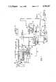
- FIG. 1is a schematic block diagram of a CD player, illustrating the standard components of a CD player and, additionally, incorporating the present invention
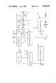
- FIG. 2is a fragmentary diagram of a portion of the system of a CD player, illustrating especially the repositioning and synchronizing arrangement of FIG. 1;
- FIG. 3is a detailed diagram of a block generator for use in the system of the present invention, and as generally shown in FIG. 1.
- FIG. 1illustrates the general structure of a CD player, as well known, and the additional feature in accordance with the present invention. For an understanding of the present invention, it is necessary to describe the well known CD player, however.
- a compact disc 10is placed on a turntable, driven by a motor 11.
- the motoris so controlled by a disc motor servo 12 that the linear speed of the spiral information tracks on the CD 10, in the form of pits carrying the information, will be essentially constant with respect to a scanning optic 13.
- the spiral information tracksrequire a change in operating speed of the motor 11 from between 500 rpm at the inner side of the disc to about 200 rpm at the edge of the disc.
- the scanning opticincludes an optical pick-up 13 which is seated on a slider or carriage 14, radially movable, and shown in FIG. 1 only symbolically by the double arrow.
- the structure and systemis well known.
- the slider 14is controlled by a slider servo 15 which controls a motor to move the slider radially, and thus provides for course tracking of the scanning optic 13 in radial direction with respect to the rotating CD 10.
- the scanning optic 13includes a semiconductor laser diode, of about 1 mW light output power, and operating in the infrared region. The beam emitted by the laser passes through a beam deflection or bending element which generates secondary beams used for tracking.
- a polarization prismprovides for linear polarization of the laser light so that, after passing through a collimated lens to be circularly polarized by a ⁇ /4 plate upon simultaneous rotation of the polarization plane about 45°.
- the ⁇ /4 plateis followed, in the beam direction, by a two-axis element which is shiftable in radial correction as well as axial direction with respect to the CD 10.
- the two-axis elementis used for two purposes: (1) for focussing of the laser beam on the information tracks.
- a focussing servo loop, including a focus servo 16is appropriately controlled to provide for focussing.
- the two-axis elementis additionally used for tracking of the laser beam and is controlled in that direction by a tracking servo 21 in such a manner that the laser beam can be shifted radially with respect to the rotating CD 10.
- the still circularly polarized lightis again linearly polarized and the polarization plane again shifted by 45°. Thereafter, the light passes through the collimating lens arrangement and linearly polarized, but rotated by 90°, impinges on the polarization prism.
- the laser lightis totally reflected and is deflected on a detection plane, which includes four separate detection fields.
- the output voltages derived from the four detection fieldsare proportional to the area scanned by the beam. Addition of the four voltages derived from the four detection fields then provides a signal having, as signal content, the analog output voltage, in radio frequency form, which is applied over a radio frequency amplifier 17 to a signal processing unit 18.
- a focus error detector 19is provided, adding the output voltages of diametrically opposite detection fields. The sums of the diametrically opposite output detection fields are subtracted from each other. Upon incorrect focussing of the two-axis element, an error voltage will result which is applied to the focus servo 16.
- the four detector fieldsdetect the main light beam.
- the detector surface of the scanning optic 13has two further auxiliary light detection fields for the auxiliary or secondary beams. These auxiliary light detection fields are used for tracking of the scanning optic 13 on the information tracks. Upon optimum tracking, the next subsequent bit in advance and behind the scanned bit is scanned at the right edge and the left edge, respectively, by the respective auxiliary beam. The reflected auxiliary beams at the auxiliary light detection fields should, upon central tracking, provide the same output voltages. If there is a tracking error, different output voltages result.
- the tracking error detector 20provides, by means of a differential amplifier, for evaluation of the output voltages of the secondary detector fields, and generates a compensating or correcting voltage, having a polarity proportional to the direction and a level representative of the extent of tracking deviation.
- This tracking correction voltageis applied to the tracking servo 21 and to the slider servo 15.
- Corresponding control voltagesare then generated by the tracking servo for the two-axis element and by the slider servo for the slider or carriage 14 of the optical system 13.
- a mirror detector 22is provided in order to prevent the tracking servo 21 from locking the main beam on the mirror positioned between the information tracks.
- the mirror detector 22is connected through the RF amplifier 17 with the output of the scanning optic 13.
- the mirror detector 22evaluates the RF voltage at the output of the scanning optic, as amplified in the amplifier 17, and provides a mirror signal in form of a recognition pulse, which rovides information if the main beam of the laser is on an information track or between the information tracks on the mirror. If the main beam should be on the information track, a maximum of rectified RA voltage will occur; if the main beam should, however, be positioned on the mirror, the voltages will be a minimum; the respective minimum voltage is detected in the mirror detector 22.
- the scanning optic 13can use the component FOP/LDX-105, commercially provided by the Sony Corporation.
- the operation of the RF amplifier 17, focus detector 19, tracking error detector 20 and mirror detector 22is all contained within an integrating circuit (IC) of the type CX 20109 by Sony.
- the focussing servo 16, tracking servo 21, and slider servo 15are available commercially as the IC CX 20108 by Sony.
- the signal processing unit 18, together with the motor servo 12,is available as the IC CX 23035 by SONY. It is associated with an external 16-kBit space RAM 23, connected thereto by a data bus 24.
- the signal processing unit 18receives the output signal from the scanning optic 13, amplified in the RF amplifier 17.
- the signal processing unit 18, initially at the inputconverts the analog signal into digital data which are processed in blocks, with intermediate storage RAM 23.
- digital audio signalswhich, after filtering in digital filter 25, are converted in a D/A converter 26 into analog output signals for application through respective low-pass filters (LPFs) to output terminals L and R, to energize respective left and right stereo channels of the audio section of a car radio, receiver, or the like.
- LPFslow-pass filters
- a subcode blockis used in the signal processing, for example for control purposes, which is demodulated by a subcode demodulator 27 to obtain a subcode-Q-signal with 98 bits.
- 72 data-Q-bits with 9-Q-data TNO, X, MIN, SEC, FRAME, ZERO, AMIN, ASEC AFRAMEare contained. The function of these Q-data is known and has been described above.
- the entire signal processing unit 18, including the focus servo 16, tracking servo 21 and slider servo 15are controlled by a system control central processing unit (CPU) 28 over a control bus 29.
- the system control CPU 28communicates with an input-output unit 30 which includes a display and an operating control panel.
- the system control CPUincludes a quartz controlled oscillator, as schematically indicated in FIG. 1. So far, the system is standard in the industry.
- a write-read or record-read memory 31is included in the path of the signal.
- the memory 31can be included at any desired position in the data processing path after the initial A/D conversion and before the final D/A conversion in D/A converter 26.
- the memory 31is located between the signal processing unit 18 and the digital filters 25.
- the memory 13can be a random access memory (RAM) or a first-in first-out register (FIFO memory), or may be a combination of both these elements.
- the memory 31is operated at a constant read-out frequency which is provided by a clock generator 32.
- the details of the clock generator 32are shown in FIG. 3, to which reference will be made.
- the clock generator 32includes a quartz oscillator 33 which provides a reference frequency f ref .
- the reference frequencyis divided by a first frequency divider 34 to provide a constant read-out frequency f const .
- the frequency from quartz oscillator 33is divided in a second frequency divider 35 which can be controlled to provide at least two different output frequencies f var , that is, of variable frequency in accordance with an input signal applied to terminal 35a of the frequency divider 35.
- the changeable or variable frequency f varis applied to the signal processing unit 18 and forms the clock frequency for the signal processing unit 18, as seen in FIG. 1.
- a repositioning system 36 and a synchronization system 37are additionally provided.
- the inventionthus, basically requires the memory 31, the repositioning system or means 36 and a synchronization system or means 37 to synchronize writing into the memory after repositioning.
- the repositioning system or arrangement 36is connected via a control bus 38 with the focussing servo 16, the tracking servo 21, and the slider servo 15, and is used to reset the scanning optic after occurrence of a tracking jump.
- the synchronization system 37is connected via control bus 39 with the control and address input of the memory 31.
- the synchronization system 37synchronizes the beginning of writing into the memory after repositioning of the scanning optic 13 by the repositioning system 36 upon termination of a prior recording of data in the memory immediately in advance of the tracking jump.
- the repositioning system 36 and the synchronizing system 37preferably, together are in form of a microprocessor.
- the repositioning system 36is shown in detail in FIG. 2, to which reference will now be made.
- the system 36includes a group of functional components which, together, provide for repositioning of the scanning head 13.
- a tracking loss detector 40is connected to a Q-data memory 41.
- a track jump control unit 43receives input from the track jump computer 42 and provides an output via bus 38 (see FIG. 1) to the servo units 15, 16 and 21.
- a mute logic 44is connected to the tracking loss detector 40, and provides a blocking signal for the stereo channels L, R of the audio portion of the CD player, by controlling a muting circuit 45 (FIG. 1).
- a timer 46is coupled to the tracking loss detector 40 and to the mute logic 44.
- the tracking loss detector 40receives the mirror signal generated by the mirror detector 22 via a signal line 47.
- the tracking loss detector 40further, receives the Q-data over Q-data line 48 from the subcode demodulator 27.
- the tracking loss detector 40is further coupled via line 49 with the control terminal 35 of the controlled frequency divider 35 (FIG. 3) of the clock generator 42.
- Line or bus 28aconnects the tracking loss detector 40 with the system control CPU 28.
- the tracking loss detector 40evaluates the mirror signal and the Q-data and detects loss of tracking of the scanning device 13, and, conversely, retracking of a track by the scanning device 13. In both cases, the tracking loss detector 40 provides a corresponding output signal.
- the Q-data supplied to the tracking loss detector 40are continuously stored in the Q-data memory 41 and applied to the track jump computer 42.
- the Q-data stored in the memory 41include at the same time all the nine Q-data which are part of a data block.
- the track jump computer 42computes the tracks jumped by the scanning optic 13 by comparison of the Q-data immediaely in advance of loss of tracking with the Q-data immediately after finding the track again. Since the Q-data contain information regarding the length of playing, the difference in representative of a time difference and, at uniform linear scanning rate, thus a measure for the number of tracks which have been jumped.
- the track jump control unit 43generates a reset signal, the level or value of which is representative of the number of tracks which have been jumped, and as computed in the track jump computer 42.
- the reset signalis applied via the control bus 38 to the tracking servo 21 (FIG. 1) which, in turn, so controls the two-axis element of the scanning optic 13 that it is moved in radial direction to return the laser beam to the original position in advance of the track jump, that is, radially with respect to the rotating CD 10.
- the synchronizing system 37essentially, includes a memory address logic 50 (FIG. 2), the input of which is coupled to the output of the tracking loss detector 40.
- a tracking loss signalis present, derived from the tracking loss detector 40, writing of digital data in the memory 31 (FIG. 1) is blocked. Blocking is released as soon as the first data word occurs of that data block which follows the entirely stored data block and last stored in the memory 31.
- the memory address logic 50additionally can store the address associated with that last prior complete data block and to so address the memory 31 that, upon reading, an address jump to the next stored address occurs as soon as the last preceding data word, that is, the last data word of the entirely stored data block before tracking loss, appears at the data output of the memory 31.
- the signal provided by the tracking loss detector 40 upon finding again the track, after loss thereof,is provided as a switch-over signal to the controlled second frequency divider 35 (FIG. 3) of the clock 32.
- the division ratio of the second frequency divider 35is so changed that the frequency f var at the output thereof is increased.
- Thisincreases the clock rate for processing of signals within the signal processing unit 18, and thus the scanning frequency of the CD plate 10 and the plate speed.
- the writing process of the digital audio signals available at the output of the signal processing unit for the memory 31is thus increased, so that memory 31 will receive data to be written therein at a higher rate.
- This increased writing frequencycauses the memory 31 to be rapidly filled with new data so that, in case of a new tracking loss, a sufficiently high quantity of data is available within memory 31.
- This sufficiently large quantity of datacan be made audible during the tracking loss and subsequent repositioning of the scanning optic 13 on the previously lost position, by continuous read-out of the memory 31 at its normal or constant reproducing or reading-out rate, as determined by the frequency divider 34 (FIG. 3).
- the elements primarily usedare the memory 31, the repositioning system 36 and the synchronizing system 37.
- memory 31Upon beginning of playing a CD 10, memory 31 is first filled with digital data derived from the signal processing unit 18.
- the memory address logic 50(FIG. 2) releases the output of the memory 31 only after the memory 31 is full.
- the stored datacan then be read-out or reproduced continuously with the constant reading frequency f const , derived from the first frequency divider 34 (FIG. 2), for transmission to the digital filter 25.
- a writing or recording of new digital datacan occur, with a writing frequency f var , so that new digital data obtained from the output of the signal processing unit 18 can be written in the memory 31.
- the tracking loss detector 40supervises the Q-data line 48 and the signalling line 47 to the mirror detector 22 (FIG. 1).
- the Q-data which are applied to the tracking loss detectornamely the data TNO, X, MIN, SEC, FRAME and/or AMIN, ASEC and AFRAME are continuously stored in the Q-data memory 41.
- Tracking lossis sensed by monitoring the RF level at the output of the scanning optic 13. Upon loss of tracking, the RF level at the output of the scanning optic 13 collapses. The mirror signal then will drop below a predetermined or preset level or threshold. Further, the Q-data are no longer available.
- the tracking loss detector 40can readily recognize a tracking loss and provides a tracking loss signal, for example in form of a suitable pulse or pulse sequence or data, to the mute logic 44 which, in turn, provides a blocking signal to the muting circuit 45 (FIG. 1). This blocks the muting circuit so that the muting which would, otherwise, occur, in the CD player, is inhibited, and muting of the audio signal is prevented.
- the tracking loss signalactivates the track jump computer 42 via connecting line 40a.
- the tracking servo 21positions the optical scanner 13 after tracking oss on any randomly available track.
- the new data TN 1 , MIN 1 , SEC 1 , FRAM 1 and/or AMIN 1 , ASEC 1 , AFRAME 1will then be applied to the tracking loss detector 40 as new Q-data. They are, in turn, recorded in the Q-data memory 41, via line 40b and additionally applied via line 40c to the track jump computer 42.
- the last-stored data written into the Q-memory 41 immediately preceding tracking lossare read-out and applied via line 41a to the track jump computer 42.
- the difference of the Q-data prior to loss of tracking and after finding a new trackpermits the track jump computer to calculate the number of the tracks which have been jumped by the scanning optic--considering the aforementioned timing, and hence distance relationships.
- the track jump control unit 43based on the number of computed tracks which have been jumped, then will generate a reset signal via bus 38 to the tracking servo 21 (FIG. 1) of such magnitude and direction that the scanning optic 13 is repositioned on a data block which precedes the data block which was last completely stored in the memory 31 prior to loss of tracking.
- the memory 31must have such a memory capacity that continuous read-out of data from a loss of tracking up to new scanning of the last entirely stored data block BV in advance of tracking loss is insured. During this time, no data are recorded in the memory 31.
- the data writing processis continued as soon as the first data word of the data block B V+1 is available at the input of the memory 31.
- the data block B V+1is that data block which immediately follows the data block B V and last recorded in its entirety in the memory 31 before loss of tracking.
- the memory address logic 50(FIG. 2) stores the address A V+1 which is associated with the data block B V+1 .
- the memory address logic 50As soon as the last data word of the entirely stored data block B V , that is, the data block recorded before loss of tracking, has been read-out from memory 31, the memory address logic 50 generates an address jump to the address A V+1 whichis the first data word of the data block B V+1 . Thus, read-out of the memory 31 is continued with the first and all subsequent data words of the data block B V+1 , and read-out of data will be continuous, thereby insuring continuous supply of data to the digital filter 25, and continued reproduction of the audio signal.
- the tracking loss detectorprovides a control signal over line 49 to the clock generator 32 (FIG. 3), and specifically to terminal 35a of the second and controlled frequency divider 35, to provide for switch-over of the division ratio thereof.
- the frequency divider 35will so change the frequency division that the variable clock frequency f var applied to the signal processing unit 18 (FIG. 1) is increased. This increase in frequency increases the speed of the CD, causing an increase in scanning speed of the CD 10, and a higher writing speed for the memory 31, so that the memory 31 is rapidly refilled again.
- the transfer signal at the input 35a of the second frequency dividerdisappears, and the output of the frequency divider 35 reverts to the standard and old frequency value.
- the memory 31can be placed at any suitable position within the signal processing path of the signal processing unit 18, that is, between the input A/D conversion and the final output D/A converter 26. It is shown separately in the drawings for ease of explanation, although the function thereof is readily combinable with other components, for example with the RAM 23, merely by increasing the memory capacity of the RAM 23 over that otherwise required for mere operation of the signal processing unit 18.
- the mirror detector signalpermits generation of a signal which has information content regarding the presence of the scanning optic on the information track or between tracks, that is, on the metal mirror.
- the level of the mirror signalcollapses since the scanning beams scans a minimum of high-frequency voltages.
- a tracking lossthus can be easily recognized.
- a high-frequency level available at the output of the scanning optic, forming an analog signalcan be used to detect tracking loss.
- the level of the high-frequency signallikewise collapses in similar manner until the scanning optic is again repositioned on a new information track.
- the decoded Q-dataare likewise applied to the tracking loss detector 40. Upon loss of tracking of an information track, the Q-data are no longer available. This loss can be evaluated to form a detection characteristic, separately or in addition to checking the high-frequency signal.
- the mute logic 44connected to the tracking loss detector, is so arranged that, upon tracking loss detection, the mute logic applies a blocking signal to the muting circuit 45 since, otherwise, the muting circuit which is present in the standard CD player and which mutes the output upon sensing of the mirror surface, rather than of a scanned track, would mute the audio output.
- the writing frequency f varis changeable, preferably in at least two frequency steps, although more than two frequency steps may be used; the writing frequency, after a tracking loss, is increased to a higher write-in frequency rate for writing into the write-read memory 31 until the aforementioned increased quantity of data is stored therein.
- the signal processing unit 18 as well as the servo loops for the CD drive motor 11are controlled by a single clock generator.
- This clock generatorpreferably includes a quartz oscillator 33 (FIG. 3) with two frequency dividers connected thereto; the first frequency divider provides a fixed division ratio, for standard read-out of the write-read memory; the second frequency divider 35 is variable, to provide the appropriate operating frequency both for the signal processing unit 18 as well as for the components connected to or controlled thereby, including the motor 11 for the CD 10.
- Tthe division ratio of the second frequency divider 35can be reduced for a predetermined time interval controlled, for example, by timer 46 (FIG. 2) and coupled to the tracking loss detector 40.
- the repositioning system 36 as well as the synchronizing system 37can be combined in a single microprocessor; some of the functional features thereof, shown as specific blocks in FIG. 2, can be realized by software, for example recognition of loss of input of Q-data through input bus 48, level of mirror signal and the like.
- a suitable microprocessor to form the combined repositioning system 36 and the synchronizing system 37is: TMS 7000 (Texas Instruments).
Landscapes
- Engineering & Computer Science (AREA)
- Signal Processing (AREA)
- Multimedia (AREA)
- Optical Recording Or Reproduction (AREA)
- Moving Of The Head For Recording And Reproducing By Optical Means (AREA)
- Optical Record Carriers And Manufacture Thereof (AREA)
- Packaging For Recording Disks (AREA)
Abstract
Description
______________________________________ synchronizing bits control bits monitoring bits 72 data Q bits having 9 Q-data: TNO: number of the music piece X: characteristic of the chopping rate MIN SEC FRAME data regarding playing time and ZERO title in binary coded decimal AMIN (BCD) code ASEC AFRAME ______________________________________
Claims (22)
Applications Claiming Priority (2)
| Application Number | Priority Date | Filing Date | Title |
|---|---|---|---|
| DE3619258 | 1986-06-07 | ||
| DE19863619258DE3619258A1 (en) | 1986-06-07 | 1986-06-07 | COMPACT DISC (CD) PLAYER |
Publications (1)
| Publication Number | Publication Date |
|---|---|
| US4796247Atrue US4796247A (en) | 1989-01-03 |
Family
ID=6302550
Family Applications (1)
| Application Number | Title | Priority Date | Filing Date |
|---|---|---|---|
| US07/054,688Expired - LifetimeUS4796247A (en) | 1986-06-07 | 1987-05-27 | Compact disc (CD) player and method of compensating for tracking jumps |
Country Status (4)
| Country | Link |
|---|---|
| US (1) | US4796247A (en) |
| EP (1) | EP0249781B2 (en) |
| AT (1) | ATE84898T1 (en) |
| DE (2) | DE3619258A1 (en) |
Cited By (59)
| Publication number | Priority date | Publication date | Assignee | Title |
|---|---|---|---|---|
| US4860272A (en)* | 1986-09-19 | 1989-08-22 | Kabushiki Kaisha Toshiba | Erroneous track jump restoration apparatus for optical record disc player |
| US4882642A (en)* | 1987-07-02 | 1989-11-21 | International Business Machines Corporation | Sequentially processing data in a cached data storage system |
| US4932018A (en)* | 1987-11-19 | 1990-06-05 | Sanyo Electric Co., Ltd. | Integrated circuit for generating indexing data in a CD player |
| US4956803A (en)* | 1987-07-02 | 1990-09-11 | International Business Machines Corporation | Sequentially processing data in a cached data storage system |
| DE3936694A1 (en)* | 1989-05-22 | 1990-11-29 | Mitsubishi Electric Corp | SEMICONDUCTOR COMPONENT WITH GRID STRUCTURE |
| US5099464A (en)* | 1987-11-30 | 1992-03-24 | Sony Corporation | Magneto optical disk recording apparatus including a plurality of connected recording unit buffer memories |
| EP0400810A3 (en)* | 1989-05-31 | 1992-05-20 | Sony Corporation | Optical disk reproducing apparatus |
| US5134598A (en)* | 1989-08-18 | 1992-07-28 | Sony Corporation | Disk player with peak level detection during high-speed playback |
| US5134563A (en)* | 1987-07-02 | 1992-07-28 | International Business Machines Corporation | Sequentially processing data in a cached data storage system |
| US5134500A (en)* | 1989-04-03 | 1992-07-28 | Pioneer Electronic Corporation | Video disk player with disk code demodulation using reproduced sync signal |
| US5173888A (en)* | 1989-06-05 | 1992-12-22 | Samsung Electronics Co., Ltd. | Playback system for audio memory disks |
| US5177729A (en)* | 1989-07-10 | 1993-01-05 | Pioneer Electronic Corporation | Method and apparatus for reading information on information recording medium having track structure |
| US5187697A (en)* | 1989-06-12 | 1993-02-16 | Pioneer Electronic Corporation | Method of reading recorded information from information storage medium with tracks |
| US5195068A (en)* | 1988-09-22 | 1993-03-16 | Yamaha Corporation | Track-number computing equipment for CLV disk drives |
| US5199019A (en)* | 1989-06-30 | 1993-03-30 | Matsushita Electric Industrial Co., Ltd. | Digital signal information reproduction apparatus enabling recording medium subsitution during reproduction of a prior recording medium |
| US5214631A (en)* | 1990-06-29 | 1993-05-25 | Sony Corporation | Disc recording/reproducing apparatus having a servo system capable of successively recording and reproducing tracks on a disc irrespective of turbulence of the servo system due to a disturbance |
| US5224089A (en)* | 1989-06-30 | 1993-06-29 | Matsushita Electric Industrial Co., Ltd. | Digital signal information reproduction apparatus |
| US5285432A (en)* | 1989-10-31 | 1994-02-08 | Kabushiki Kaisha Toshiba | Track jump control circuit |
| US5291467A (en)* | 1991-07-16 | 1994-03-01 | Sony Corporation | Disc recording apparatus for recording a signal without losing the signal during an occurrence of a track jump |
| US5337295A (en)* | 1991-05-25 | 1994-08-09 | Sony Corporation | Digital audio signal reproducing apparatus |
| US5406537A (en)* | 1992-07-14 | 1995-04-11 | Samsung Electronics Co., Ltd. | System for reproducing an optical disc |
| JPH07130096A (en)* | 1980-07-16 | 1995-05-19 | Discovision Assoc | Method and apparatus for restoration of information |
| US5436875A (en)* | 1993-07-13 | 1995-07-25 | Sony Corporation | Recording/reproducing apparatus having buffer memory for preventing discontinuity in recording/reproducing operations and method for same |
| US5450388A (en)* | 1991-02-09 | 1995-09-12 | Deutsche Thomson-Brandt Gmbh | Method for correcting tracking errors in a disc record reproduction apparatus |
| US5453964A (en)* | 1992-03-31 | 1995-09-26 | Sony Corporation | Data processing circuit for disc player |
| US5457670A (en)* | 1992-12-09 | 1995-10-10 | Pioneer Electronic Corporation | Optical disk information recording apparatus and reproducing apparatus having a plurality of read or write beams |
| US5485443A (en)* | 1991-06-19 | 1996-01-16 | Mitsubishi Denki Kabushiki Kaisha | Recording and reproducing system |
| US5491676A (en)* | 1991-12-09 | 1996-02-13 | Matsushita Electric Industrial Co., Ltd. | Tracking control apparatus and track jump detection apparatus |
| US5493676A (en)* | 1993-06-29 | 1996-02-20 | Unisys Corporation | Severe environment data recording system |
| US5502701A (en)* | 1992-02-29 | 1996-03-26 | Sony Corporation | Optical disc recording apparatus which controls re-recording after a disturbance as a function of the capacity of an input buffer memory |
| US5502700A (en)* | 1992-07-09 | 1996-03-26 | Sony Corporation | Power saving method and apparatus for intermittently reading reproduction apparatus |
| US5506821A (en)* | 1993-05-27 | 1996-04-09 | Applied Media Technologies Corporation | Optical disk program repeater |
| US5508983A (en)* | 1993-12-22 | 1996-04-16 | Sony Corporation | Optical disc player with shockproof controller and method of processing reproduction data |
| US5517477A (en)* | 1990-01-19 | 1996-05-14 | Sony Corporation | Data recording method and data reproducing apparatus |
| US5590112A (en)* | 1993-12-08 | 1996-12-31 | Yamaha Corporation | Track jump controller for correcting information read errors |
| US5606467A (en)* | 1990-09-17 | 1997-02-25 | Fuji Photo Film Co., Ltd. | Apparatus for continuous recording and reproducing of data from a magnetic tape cassette comprising a semiconductor memory |
| US5699336A (en)* | 1995-01-25 | 1997-12-16 | Sony Corporation | Reproducing apparatus having buffer memory and capable of rapidly restarting reproduction and method of controlling the apparatus |
| WO1998003975A3 (en)* | 1996-07-20 | 1998-02-26 | Philips Electronics Nv | Method and apparatus for reading data from a disc carrier |
| RU2107954C1 (en)* | 1990-08-23 | 1998-03-27 | Сони Корпорейшн | Disk information carrier, writing device, reading device and reading-writing device |
| US5734731A (en)* | 1994-11-29 | 1998-03-31 | Marx; Elliot S. | Real time audio mixer |
| US5870365A (en)* | 1996-04-19 | 1999-02-09 | Matsushita Electric Industrial Co., Ltd. | Start ID recording system for use in a digital audio information recording apparatus |
| US5901119A (en)* | 1996-08-23 | 1999-05-04 | Sony Corporation | Recording apparatus, playback apparatus and recording medium having a management area with program position and playback information |
| USRE36218E (en)* | 1990-06-29 | 1999-06-01 | Sony Corporation | Disc recording/reproducing apparatus having a servo system capable of successively recording and reproducing tracks on a disc irrespective of turbulence of the servo system due to a disturbance |
| US6115337A (en)* | 1994-12-16 | 2000-09-05 | Deutsche Thomson-Brandt Gmbh | Vibration-resistant playback device |
| EP1028415A3 (en)* | 1993-10-07 | 2000-10-04 | Sony Corporation | Rotation servo circuit in disk player |
| US6154429A (en)* | 1997-09-30 | 2000-11-28 | Deutsche Thomson-Brandt Gmbh | Device for reading from and/or writing to optical recording media |
| US6160785A (en)* | 1997-03-12 | 2000-12-12 | Deutsche Thomson-Brandt Gmbh | Method and apparatus for the processing and outputting of data |
| US6181653B1 (en)* | 1991-11-25 | 2001-01-30 | Sony Corporation | Disc reproducing and recording apparatus with display of the amount of data in a buffer memory |
| US6282157B1 (en)* | 1997-11-11 | 2001-08-28 | Samsung Electronics Co., Ltd | Tracking and focusing control apparatus in an optical disk system |
| GB2363556A (en)* | 2000-05-12 | 2001-12-19 | Global Silicon Ltd | Digital audio processing |
| EP1197964A1 (en)* | 1996-07-25 | 2002-04-17 | Sony Corporation | Disk drive device and method of setting rotational speed thereof |
| DE19757058C2 (en)* | 1997-09-23 | 2002-08-29 | United Microelectronics Corp | Compact disc player system with vibration-insensitive, uninterrupted playability |
| US20020161858A1 (en)* | 1994-01-25 | 2002-10-31 | Robert Goldman | Digital audio system for radio stations |
| US6477123B1 (en)* | 1997-03-29 | 2002-11-05 | Thomson Licensing S.A. | Device for CD reproduction with variable speed or direction |
| US20050083809A1 (en)* | 2003-10-15 | 2005-04-21 | Casio Computer Co., Ltd. | Data reproducing apparatus and program for performing a data reproducing process |
| WO2007140524A1 (en)* | 2006-06-05 | 2007-12-13 | Mark Costa | Audio system for vehicles |
| US20090122669A1 (en)* | 2005-11-30 | 2009-05-14 | Junichi Minamino | Optical disc device |
| US20090257330A1 (en)* | 2008-04-11 | 2009-10-15 | Hideki Maruyama | Optical disc drive apparatus and its control method |
| US7881167B1 (en)* | 2005-09-23 | 2011-02-01 | Apple Inc. | Systems and methods of shock recovery in writable optical disc systems |
Families Citing this family (7)
| Publication number | Priority date | Publication date | Assignee | Title |
|---|---|---|---|---|
| WO1991011002A1 (en)* | 1990-01-19 | 1991-07-25 | Sony Corporation | Data recording and reproducing methods |
| CA2047664C (en)* | 1990-01-19 | 1999-09-28 | Yoichiro Sako | Data recording method and data reproducing apparatus |
| JP3049919B2 (en)* | 1992-01-31 | 2000-06-05 | ソニー株式会社 | Data playback device |
| WO1993001596A1 (en)* | 1991-07-02 | 1993-01-21 | Deutsche Thomson-Brandt Gmbh | Process for shortening the access time (track control circuit) |
| EP0607861B1 (en)* | 1993-01-21 | 2000-04-05 | Hitachi, Ltd. | Disk reproducing apparatus |
| DE4445013A1 (en)* | 1994-12-16 | 1996-06-20 | Thomson Brandt Gmbh | Vibration-resistant player with improved synchronization |
| DE19650054B4 (en)* | 1996-12-03 | 2009-04-09 | Robert Bosch Gmbh | Turntable for playing records with optically stored data |
Citations (1)
| Publication number | Priority date | Publication date | Assignee | Title |
|---|---|---|---|---|
| US4698796A (en)* | 1983-08-22 | 1987-10-06 | Sony Corporation | Disk recording and/or reproducing apparatus with compensation for extraneous force during track jump |
Family Cites Families (5)
| Publication number | Priority date | Publication date | Assignee | Title |
|---|---|---|---|---|
| NL8300844A (en)* | 1983-03-09 | 1984-10-01 | Philips Nv | DEVICE FOR READING AN OPTICALLY CODED DISC REGISTRATION CARRIER. |
| NL8303061A (en)* | 1983-09-02 | 1985-04-01 | Philips Nv | DEVICE FOR READING AN OPTICALLY READABLE RECORD CARRIER. |
| NL8303565A (en)* | 1983-10-17 | 1985-05-17 | Philips Nv | Apparatus for displaying information from a plate-shaped optically readable record carrier. |
| JPS60154358A (en)* | 1984-01-20 | 1985-08-14 | Pioneer Electronic Corp | Reproducing device of recorded information |
| NL8502635A (en)* | 1985-09-27 | 1987-04-16 | Philips Nv | DEVICE FOR READING INFORMATION ON A RECORD CARRIER. |
- 1986
- 1986-06-07DEDE19863619258patent/DE3619258A1/ennot_activeCeased
- 1987
- 1987-05-27USUS07/054,688patent/US4796247A/ennot_activeExpired - Lifetime
- 1987-05-29EPEP87107797Apatent/EP0249781B2/ennot_activeExpired - Lifetime
- 1987-05-29ATAT87107797Tpatent/ATE84898T1/ennot_activeIP Right Cessation
- 1987-05-29DEDE8787107797Tpatent/DE3783660D1/ennot_activeExpired - Lifetime
Patent Citations (1)
| Publication number | Priority date | Publication date | Assignee | Title |
|---|---|---|---|---|
| US4698796A (en)* | 1983-08-22 | 1987-10-06 | Sony Corporation | Disk recording and/or reproducing apparatus with compensation for extraneous force during track jump |
Cited By (79)
| Publication number | Priority date | Publication date | Assignee | Title |
|---|---|---|---|---|
| JPH07130096A (en)* | 1980-07-16 | 1995-05-19 | Discovision Assoc | Method and apparatus for restoration of information |
| US4860272A (en)* | 1986-09-19 | 1989-08-22 | Kabushiki Kaisha Toshiba | Erroneous track jump restoration apparatus for optical record disc player |
| US4882642A (en)* | 1987-07-02 | 1989-11-21 | International Business Machines Corporation | Sequentially processing data in a cached data storage system |
| US4956803A (en)* | 1987-07-02 | 1990-09-11 | International Business Machines Corporation | Sequentially processing data in a cached data storage system |
| US5134563A (en)* | 1987-07-02 | 1992-07-28 | International Business Machines Corporation | Sequentially processing data in a cached data storage system |
| US4932018A (en)* | 1987-11-19 | 1990-06-05 | Sanyo Electric Co., Ltd. | Integrated circuit for generating indexing data in a CD player |
| US5099464A (en)* | 1987-11-30 | 1992-03-24 | Sony Corporation | Magneto optical disk recording apparatus including a plurality of connected recording unit buffer memories |
| US5195068A (en)* | 1988-09-22 | 1993-03-16 | Yamaha Corporation | Track-number computing equipment for CLV disk drives |
| US5134500A (en)* | 1989-04-03 | 1992-07-28 | Pioneer Electronic Corporation | Video disk player with disk code demodulation using reproduced sync signal |
| DE3936694A1 (en)* | 1989-05-22 | 1990-11-29 | Mitsubishi Electric Corp | SEMICONDUCTOR COMPONENT WITH GRID STRUCTURE |
| US5148417A (en)* | 1989-05-31 | 1992-09-15 | Sony Corporation | Tracking jump compensator for optical disc reproducing apparatus |
| EP0400810A3 (en)* | 1989-05-31 | 1992-05-20 | Sony Corporation | Optical disk reproducing apparatus |
| US5173888A (en)* | 1989-06-05 | 1992-12-22 | Samsung Electronics Co., Ltd. | Playback system for audio memory disks |
| US5187697A (en)* | 1989-06-12 | 1993-02-16 | Pioneer Electronic Corporation | Method of reading recorded information from information storage medium with tracks |
| US5199019A (en)* | 1989-06-30 | 1993-03-30 | Matsushita Electric Industrial Co., Ltd. | Digital signal information reproduction apparatus enabling recording medium subsitution during reproduction of a prior recording medium |
| US5224089A (en)* | 1989-06-30 | 1993-06-29 | Matsushita Electric Industrial Co., Ltd. | Digital signal information reproduction apparatus |
| US5177729A (en)* | 1989-07-10 | 1993-01-05 | Pioneer Electronic Corporation | Method and apparatus for reading information on information recording medium having track structure |
| US5134598A (en)* | 1989-08-18 | 1992-07-28 | Sony Corporation | Disk player with peak level detection during high-speed playback |
| US5285432A (en)* | 1989-10-31 | 1994-02-08 | Kabushiki Kaisha Toshiba | Track jump control circuit |
| US5517477A (en)* | 1990-01-19 | 1996-05-14 | Sony Corporation | Data recording method and data reproducing apparatus |
| US5214631A (en)* | 1990-06-29 | 1993-05-25 | Sony Corporation | Disc recording/reproducing apparatus having a servo system capable of successively recording and reproducing tracks on a disc irrespective of turbulence of the servo system due to a disturbance |
| USRE36218E (en)* | 1990-06-29 | 1999-06-01 | Sony Corporation | Disc recording/reproducing apparatus having a servo system capable of successively recording and reproducing tracks on a disc irrespective of turbulence of the servo system due to a disturbance |
| EP1526533A2 (en) | 1990-06-29 | 2005-04-27 | Sony Corporation | Disc reproducing apparatus |
| EP1526533A3 (en)* | 1990-06-29 | 2009-09-23 | Sony Corporation | Disc reproducing apparatus |
| EP1526537A2 (en) | 1990-06-29 | 2005-04-27 | Sony Corporation | Disc reproducing apparatus |
| EP0465053B1 (en)* | 1990-06-29 | 2002-08-28 | Sony Corporation | Disc recording/reproducing apparatus |
| AU645579B2 (en)* | 1990-06-29 | 1994-01-20 | Sony Corporation | Disc recording/reproducing apparatus |
| EP1526537A3 (en)* | 1990-06-29 | 2009-09-23 | Sony Corporation | Disc reproducing apparatus |
| RU2107954C1 (en)* | 1990-08-23 | 1998-03-27 | Сони Корпорейшн | Disk information carrier, writing device, reading device and reading-writing device |
| US5606467A (en)* | 1990-09-17 | 1997-02-25 | Fuji Photo Film Co., Ltd. | Apparatus for continuous recording and reproducing of data from a magnetic tape cassette comprising a semiconductor memory |
| US5450388A (en)* | 1991-02-09 | 1995-09-12 | Deutsche Thomson-Brandt Gmbh | Method for correcting tracking errors in a disc record reproduction apparatus |
| US5337295A (en)* | 1991-05-25 | 1994-08-09 | Sony Corporation | Digital audio signal reproducing apparatus |
| US5485443A (en)* | 1991-06-19 | 1996-01-16 | Mitsubishi Denki Kabushiki Kaisha | Recording and reproducing system |
| US5291467A (en)* | 1991-07-16 | 1994-03-01 | Sony Corporation | Disc recording apparatus for recording a signal without losing the signal during an occurrence of a track jump |
| US6181653B1 (en)* | 1991-11-25 | 2001-01-30 | Sony Corporation | Disc reproducing and recording apparatus with display of the amount of data in a buffer memory |
| US5491676A (en)* | 1991-12-09 | 1996-02-13 | Matsushita Electric Industrial Co., Ltd. | Tracking control apparatus and track jump detection apparatus |
| US5502701A (en)* | 1992-02-29 | 1996-03-26 | Sony Corporation | Optical disc recording apparatus which controls re-recording after a disturbance as a function of the capacity of an input buffer memory |
| US5563861A (en)* | 1992-02-29 | 1996-10-08 | Sony Corporation | Optical disc recording apparatus which controls re-recording after a disturbance as a function of the frequency of the detected disturbance |
| US5453964A (en)* | 1992-03-31 | 1995-09-26 | Sony Corporation | Data processing circuit for disc player |
| US5502700A (en)* | 1992-07-09 | 1996-03-26 | Sony Corporation | Power saving method and apparatus for intermittently reading reproduction apparatus |
| US5822288A (en)* | 1992-07-09 | 1998-10-13 | Sony Corporation | Power saving method and apparatus for intermittently reading reproduction apparatus |
| US5615187A (en)* | 1992-07-09 | 1997-03-25 | Sony Corporation | Power saving method and apparatus for intermittently reading reproduction apparatus |
| US5406537A (en)* | 1992-07-14 | 1995-04-11 | Samsung Electronics Co., Ltd. | System for reproducing an optical disc |
| US5572493A (en)* | 1992-12-09 | 1996-11-05 | Pioneer Electronic Corporation | Optical disk information recording apparatus and reproducing apparatus having a plurality of read or write beams |
| US5457670A (en)* | 1992-12-09 | 1995-10-10 | Pioneer Electronic Corporation | Optical disk information recording apparatus and reproducing apparatus having a plurality of read or write beams |
| US5506821A (en)* | 1993-05-27 | 1996-04-09 | Applied Media Technologies Corporation | Optical disk program repeater |
| US5493676A (en)* | 1993-06-29 | 1996-02-20 | Unisys Corporation | Severe environment data recording system |
| US5566144A (en)* | 1993-07-13 | 1996-10-15 | Sony Corporation | Recording/reproducing apparatus having buffer memory for preventing discontinuity in recording/reproducing operations and method for same |
| US5436875A (en)* | 1993-07-13 | 1995-07-25 | Sony Corporation | Recording/reproducing apparatus having buffer memory for preventing discontinuity in recording/reproducing operations and method for same |
| US6269061B1 (en) | 1993-10-07 | 2001-07-31 | Sony Corporation | Servo control system for disk player |
| EP1028415A3 (en)* | 1993-10-07 | 2000-10-04 | Sony Corporation | Rotation servo circuit in disk player |
| US5590112A (en)* | 1993-12-08 | 1996-12-31 | Yamaha Corporation | Track jump controller for correcting information read errors |
| US5508983A (en)* | 1993-12-22 | 1996-04-16 | Sony Corporation | Optical disc player with shockproof controller and method of processing reproduction data |
| US20020161858A1 (en)* | 1994-01-25 | 2002-10-31 | Robert Goldman | Digital audio system for radio stations |
| US5734731A (en)* | 1994-11-29 | 1998-03-31 | Marx; Elliot S. | Real time audio mixer |
| KR100406805B1 (en)* | 1994-12-16 | 2004-03-02 | 도이체 톰손-브란트 게엠베하 | Anti-vibration playback device |
| US6115337A (en)* | 1994-12-16 | 2000-09-05 | Deutsche Thomson-Brandt Gmbh | Vibration-resistant playback device |
| US5699336A (en)* | 1995-01-25 | 1997-12-16 | Sony Corporation | Reproducing apparatus having buffer memory and capable of rapidly restarting reproduction and method of controlling the apparatus |
| US5870365A (en)* | 1996-04-19 | 1999-02-09 | Matsushita Electric Industrial Co., Ltd. | Start ID recording system for use in a digital audio information recording apparatus |
| US5995462A (en)* | 1996-07-20 | 1999-11-30 | U.S. Philips Corporation | Method and apparatus for reading data from a disc carrier |
| WO1998003975A3 (en)* | 1996-07-20 | 1998-02-26 | Philips Electronics Nv | Method and apparatus for reading data from a disc carrier |
| EP1197964A1 (en)* | 1996-07-25 | 2002-04-17 | Sony Corporation | Disk drive device and method of setting rotational speed thereof |
| US5901119A (en)* | 1996-08-23 | 1999-05-04 | Sony Corporation | Recording apparatus, playback apparatus and recording medium having a management area with program position and playback information |
| US6160785A (en)* | 1997-03-12 | 2000-12-12 | Deutsche Thomson-Brandt Gmbh | Method and apparatus for the processing and outputting of data |
| US6477123B1 (en)* | 1997-03-29 | 2002-11-05 | Thomson Licensing S.A. | Device for CD reproduction with variable speed or direction |
| DE19757058C2 (en)* | 1997-09-23 | 2002-08-29 | United Microelectronics Corp | Compact disc player system with vibration-insensitive, uninterrupted playability |
| US6154429A (en)* | 1997-09-30 | 2000-11-28 | Deutsche Thomson-Brandt Gmbh | Device for reading from and/or writing to optical recording media |
| US6282157B1 (en)* | 1997-11-11 | 2001-08-28 | Samsung Electronics Co., Ltd | Tracking and focusing control apparatus in an optical disk system |
| US20040093099A1 (en)* | 2000-05-12 | 2004-05-13 | Brennan Martin John | Digital audio processing |
| GB2363556B (en)* | 2000-05-12 | 2004-12-22 | Global Silicon Ltd | Digital audio processing |
| GB2363556A (en)* | 2000-05-12 | 2001-12-19 | Global Silicon Ltd | Digital audio processing |
| US8010214B2 (en) | 2000-05-12 | 2011-08-30 | Gs Ip Limited Liability Company | Digital audio processing |
| US20050083809A1 (en)* | 2003-10-15 | 2005-04-21 | Casio Computer Co., Ltd. | Data reproducing apparatus and program for performing a data reproducing process |
| US7881167B1 (en)* | 2005-09-23 | 2011-02-01 | Apple Inc. | Systems and methods of shock recovery in writable optical disc systems |
| US20090122669A1 (en)* | 2005-11-30 | 2009-05-14 | Junichi Minamino | Optical disc device |
| US8072852B2 (en)* | 2005-11-30 | 2011-12-06 | Panasonic Corporation | Optical disc device |
| WO2007140524A1 (en)* | 2006-06-05 | 2007-12-13 | Mark Costa | Audio system for vehicles |
| US20090257330A1 (en)* | 2008-04-11 | 2009-10-15 | Hideki Maruyama | Optical disc drive apparatus and its control method |
| US8134902B2 (en)* | 2008-04-11 | 2012-03-13 | Hitachi, Ltd. | Optical disc drive apparatus and its control method |
Also Published As
| Publication number | Publication date |
|---|---|
| EP0249781B1 (en) | 1993-01-20 |
| EP0249781A3 (en) | 1989-12-20 |
| EP0249781A2 (en) | 1987-12-23 |
| DE3783660D1 (en) | 1993-03-04 |
| EP0249781B2 (en) | 1998-07-22 |
| ATE84898T1 (en) | 1993-02-15 |
| DE3619258A1 (en) | 1987-12-10 |
Similar Documents
| Publication | Publication Date | Title |
|---|---|---|
| US4796247A (en) | Compact disc (CD) player and method of compensating for tracking jumps | |
| US4761775A (en) | Optical disc using tracking and clocking prepits and address prepits between adjacent ones of the tracking and clocking prepits, and an optical apparatus using such a disc | |
| US4603412A (en) | Disc rotation servo control apparatus in a disc player | |
| RU2024072C1 (en) | Method of optical recording and device to implement it | |
| EP1118981B1 (en) | Optical disc reading system | |
| CA1319985C (en) | Method of and apparatus for recording an information signal | |
| EP0442566B1 (en) | Information recording device | |
| JP3029201B2 (en) | Optically readable writable record carrier, device for manufacturing such a record carrier, and device for recording / reproducing information using such a record carrier | |
| EP0083475A1 (en) | Optical data recording and reproducing apparatus | |
| EP0178657A2 (en) | Apparatus for recording and/or reproducing data signal on or from disk sharped recording medium | |
| US4688205A (en) | Data demodulation apparatus | |
| EP0193961B1 (en) | Information selection device of disc player | |
| US5642342A (en) | Apparatus for controlling the rotational speed of an optical-disc | |
| EP0714096B1 (en) | Disc player | |
| US6452882B1 (en) | Method of compensating for an eccentricity of an optical disc and apparatus for doing the same | |
| US5402403A (en) | Device for detecting cross talk level of optically read signal | |
| US5737284A (en) | Optical disc drive having accessing from a current position within a lead-in area | |
| US5214629A (en) | Optical disc having a high-speed access capability and reading apparatus therefor | |
| EP0372953B1 (en) | Method of, and apparatus for detecting access speed for a disc player | |
| KR0130474B1 (en) | Apparatus for reading an optically readable record carrier | |
| US5446717A (en) | Optical disc and recording and reproducing method for an optical disc with a high density | |
| US5363364A (en) | Audio data recording/reproducing apparatus having digital high-speed dubbing function | |
| KR19990082315A (en) | Information storage and playback system | |
| US5481369A (en) | Crosstalk detector for optically read signals | |
| US5724326A (en) | Apparatus for generating track count pulse |
Legal Events
| Date | Code | Title | Description |
|---|---|---|---|
| AS | Assignment | Owner name:BLAUPUNKT-WERKE GMBH, ROBERT-BOSCH-STRASSE 200 D-3 Free format text:ASSIGNMENT OF ASSIGNORS INTEREST.;ASSIGNOR:VOGELSANG, ULRICH;REEL/FRAME:004715/0867 Effective date:19870511 Owner name:BLAUPUNKT-WERKE GMBH, GERMANY Free format text:ASSIGNMENT OF ASSIGNORS INTEREST;ASSIGNOR:VOGELSANG, ULRICH;REEL/FRAME:004715/0867 Effective date:19870511 | |
| STCF | Information on status: patent grant | Free format text:PATENTED CASE | |
| FEPP | Fee payment procedure | Free format text:PAYOR NUMBER ASSIGNED (ORIGINAL EVENT CODE: ASPN); ENTITY STATUS OF PATENT OWNER: LARGE ENTITY | |
| FPAY | Fee payment | Year of fee payment:4 | |
| FEPP | Fee payment procedure | Free format text:PAYER NUMBER DE-ASSIGNED (ORIGINAL EVENT CODE: RMPN); ENTITY STATUS OF PATENT OWNER: LARGE ENTITY Free format text:PAYOR NUMBER ASSIGNED (ORIGINAL EVENT CODE: ASPN); ENTITY STATUS OF PATENT OWNER: LARGE ENTITY | |
| FPAY | Fee payment | Year of fee payment:8 | |
| REFU | Refund | Free format text:REFUND - PAYMENT OF MAINTENANCE FEE, 12TH YEAR, LARGE ENTITY (ORIGINAL EVENT CODE: R185); ENTITY STATUS OF PATENT OWNER: LARGE ENTITY Free format text:REFUND - SURCHARGE FOR LATE PAYMENT, LARGE ENTITY (ORIGINAL EVENT CODE: R186); ENTITY STATUS OF PATENT OWNER: LARGE ENTITY | |
| FPAY | Fee payment | Year of fee payment:12 |