US4796110A - System and method for encoding and storing digital information on magnetic tape - Google Patents
System and method for encoding and storing digital information on magnetic tapeDownload PDFInfo
- Publication number
- US4796110A US4796110AUS06/830,559US83055986AUS4796110AUS 4796110 AUS4796110 AUS 4796110AUS 83055986 AUS83055986 AUS 83055986AUS 4796110 AUS4796110 AUS 4796110A
- Authority
- US
- United States
- Prior art keywords
- sectors
- data
- error
- correction
- words
- Prior art date
- Legal status (The legal status is an assumption and is not a legal conclusion. Google has not performed a legal analysis and makes no representation as to the accuracy of the status listed.)
- Expired - Lifetime
Links
Images


Classifications
- G—PHYSICS
- G11—INFORMATION STORAGE
- G11B—INFORMATION STORAGE BASED ON RELATIVE MOVEMENT BETWEEN RECORD CARRIER AND TRANSDUCER
- G11B5/00—Recording by magnetisation or demagnetisation of a record carrier; Reproducing by magnetic means; Record carriers therefor
- G11B5/02—Recording, reproducing, or erasing methods; Read, write or erase circuits therefor
- G11B5/09—Digital recording
- G—PHYSICS
- G11—INFORMATION STORAGE
- G11B—INFORMATION STORAGE BASED ON RELATIVE MOVEMENT BETWEEN RECORD CARRIER AND TRANSDUCER
- G11B20/00—Signal processing not specific to the method of recording or reproducing; Circuits therefor
- G11B20/10—Digital recording or reproducing
- G11B20/18—Error detection or correction; Testing, e.g. of drop-outs
- G11B20/1806—Pulse code modulation systems for audio signals
- G11B20/1809—Pulse code modulation systems for audio signals by interleaving
- G—PHYSICS
- G11—INFORMATION STORAGE
- G11B—INFORMATION STORAGE BASED ON RELATIVE MOVEMENT BETWEEN RECORD CARRIER AND TRANSDUCER
- G11B20/00—Signal processing not specific to the method of recording or reproducing; Circuits therefor
- G11B20/10—Digital recording or reproducing
- G11B20/12—Formatting, e.g. arrangement of data block or words on the record carriers
- G11B20/1201—Formatting, e.g. arrangement of data block or words on the record carriers on tapes
- G11B20/1202—Formatting, e.g. arrangement of data block or words on the record carriers on tapes with longitudinal tracks only
- G11B20/1205—Formatting, e.g. arrangement of data block or words on the record carriers on tapes with longitudinal tracks only for discontinuous data, e.g. digital information signals, computer programme data
- G—PHYSICS
- G11—INFORMATION STORAGE
- G11B—INFORMATION STORAGE BASED ON RELATIVE MOVEMENT BETWEEN RECORD CARRIER AND TRANSDUCER
- G11B20/00—Signal processing not specific to the method of recording or reproducing; Circuits therefor
- G11B20/10—Digital recording or reproducing
- G11B20/12—Formatting, e.g. arrangement of data block or words on the record carriers
- G11B20/1201—Formatting, e.g. arrangement of data block or words on the record carriers on tapes
- G11B20/1202—Formatting, e.g. arrangement of data block or words on the record carriers on tapes with longitudinal tracks only
- G—PHYSICS
- G11—INFORMATION STORAGE
- G11B—INFORMATION STORAGE BASED ON RELATIVE MOVEMENT BETWEEN RECORD CARRIER AND TRANSDUCER
- G11B2220/00—Record carriers by type
- G11B2220/90—Tape-like record carriers
Definitions
- the present inventionrelates to systems and methods for writing digital information on magnetic tapes, and more particularly to such systems and methods for generating and storing redundant information with the digital information on the tape.
- CMOS random access memoryprovides the fastest response time, but has the highest cost per byte.
- magnetic tapehas the slowest response time, but the lowest cost per byte stored.
- diskswhich provide response time and cost per byte in between those for RAM and tape. Such disks include hard disks, "Winchester” disks, and floppy disks.
- CMOS RAMcan lose its information if a circuit malfunctions or if "noise" exists on a communication bus. Information can be lost on disks, tapes, and other magnetic surfaces by a magnetic field, physical damage to the magnetic surface, or noise on the communication bus. Other causes of information loss include software which "goes haywire” or programmer/operator error. This lost information is generally referred to as "erasures”. It is therefore desirable and commonly accepted within the computer industry to provide cost effective “backup” for the various memory devices. "Backup” involves periodically storing the contents of a first storage device on a second storage device, so that the contents of the first storage device can be restored or recovered in the event of damage to, or information loss from, the first storage device.
- Redundant information calculated using this methodtypically requires less space than a complete second copy of the data information, while still enabling recovery from at least some loss of information.
- redundant informationis stored in blocks physically separate from the data blocks; and a look-up table is provided on the tape to provide a mapping between the data blocks and the corresponding redundant blocks.
- This approachalso has its drawbacks. If the look-up table is erased or otherwise lost, it is impossible to determine the correspondence between the data blocks and the redundant blocks required to read the redundant information and restore the data information to the disk. Additionally, both the writing and reading are undesirably slow because the mapping table must be repeatedly consulted and the various data and redundant blocks accessed at separate locations on the tape.
- the data informationis formatted into data sectors
- redundant informationis calculated for a group of data sectors and stored in one or more redundant sectors
- the group of data sectors and the corresponding redundant sectorsare written sequentially to the tape as a block of information.
- the redundant sectorsare written sequentially at the beginning or end of each block.
- the methodincludes the steps of (1) formatting the data information into groups of data words, (2) calculating one or more redundant words for each group using a Reed-Solomon code, and (3) writing the related data and redundant words to the tape as a block of backup information.
- a Reed-Solomon codeimproves both the efficiency and the speed at which the backup system operates.
- the chosen Reed-Solomon codeis a "high rate" code meaning that relatively little redundant information is required to correct a relatively large number of erasures.
- the codeis a "systematic" code meaning that the original data is unchanged during storage, so that decoding is unnecessary if erasures do not occur.
- the redundant informationcan be readily encoded with a relatively fast algorithm and/or a relatively simple hardware configuration.
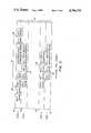
- FIG. 1shows a conceptual block of backup information including data and redundant sectors as generated by the present invention
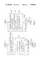
- FIG. 2shows the physical tape format of the backup blocks
- FIGS. 3-7are flow charts showing the progam flow of the encoding and decoding software.
- each data word or redundant wordincludes a single byte.
- the present inventionis applicable to and encompasses multibyte words also.
- the data bytesare arranged or formatted into sectors, each of which contains 1024 (1k) bytes. For every 16 data sectors, two sectors of redundant bytes are created. Each byte in each redundant sector is a function of the corresponding bytes in the sixteen data sectors. A total of 18 sectors--sixteen data sectors and two redundant sectors--comprise a block.
- the format of the tape and the encoding of the redundant informationcomprise two aspects of the present invention.
- the backup system of the present inventionis capable of storing 20 megabytes (20 M) of data information on a single data cartridge.
- the construction of the backup unitis generally well-known to those having ordinary skill in the art, for example as illustrated in the above-noted U.S. patent application No. 589,007 and U.S. Pat. Nos. 4,472,750 and 4,468,712.
- Such data tape driveshave been manufactured and sold by the assignee of the present application as Models 110 and 310.
- the data cartridgesare those sold as Models TC200 and TC400 by Irwin Magnetic Systems, Inc. of Ann Arbor, Mich.; those manufactured and sold as Models DC1000 and DC2000 by Minnesota Mining and Manufacturing Company of Minneapolis, Minn.; and those manufactured and sold as Models Microtape 1000 and Microtape 2000 by Data Electronics, Incorporated of San Diego, Calif.
- FIG. 1The conceptual format of a tape encoded utilizing the system and method of the present invention is illustrated in FIG. 1.
- the data information received from the diskis formatted into sectors, each of which includes 1024 8-bit bytes. Sixteen data sectors are included within each block 10 and are denoted DATA 1 through DATA 16. Consequently, each block 10 includes sixteen kilobytes of data information.
- the words within each sectorare sequentially ordered and denominated 0-1023.
- the sectorsare arranged in table format with corresponding words in each sector (e.g. word 0 of each sector) arranged side by side.
- the bytes within each corresponding sector at a given locationare hereinafter referred to as corresponding data bytes.
- ECC 1 and ECC 2For each group of sixteen corresponding bytes (one byte from each of the sixteen data sectors), two redundant bytes are generated. These bytes are sequentially ordered in two sectors denoted ECC 1 and ECC 2. One byte in each of the ECC sectors corresponds to one byte in each of the sixteen data sectors and therefore to a group of sixteen corresponding data bytes.
- the two ECC sectorsare generated from the sixteen data sectors utilizing a Reed-Solomon encoding scheme.
- Two ECC bytesare generated for each group of corresponding data bytes by "folding" the sixteen data bytes and the two ECC bytes together. Suffice it to say at this point that the two redundant bytes are of such a nature, quality, and/or quantity to enable the unique reconstruction or restoration of any two erased bytes (either data or ECC) based on the remaining sixteen bytes in the group.
- the conceptual block 10 as illustrated in FIG. 1is generated within RAM and subsequently written to the tape 12 as illustrated in FIG. 2. All 18 sectors of the physical block are written sequentially on one track of the tape 12. Physically, the sixteen data sectors are written first followed by the two ECC sectors. The ECC sectors have the same physical location in every block. Consequently, a map is not required between the data sectors and/or the ECC sectors in order to locate and correlate this information.
- the 1024 bytes within each sectorare written sequentially to the tape. As is routine to those having skill in the art, appropriate header information is included at the beginning of each sector; and appropriate header information is written at the beginning of each block, for example at point 26 (FIG. 2).
- the tapepreferably includes 12 tracks denoted track 0 through track 11 identified by designating numerals 28, 30, 32, and 34.
- the blocks 10are written to the tape 12 in serpentine format. Specifically, track 0 is first filled from a first end of the tape to second end of the tape; track one is then filled from the second end of the tape to the first end of the tape; and so forth.
- the physical length of each sector of 1024 bytesis approximately 1 inch.
- the error-correction informationis generated using a Reed-Solomon code.
- the implementation of a Reed-Solomon codeis generally well-known to those having ordinary skill in the data transmission art.
- the symbols or bytes of a codeword in a Reed-Solomon codeare elements in a finite field known as a Galois field.
- the Galois fieldis selected to have 256 elements because the 8-bit data bytes are capable of defining 256 different bytes.
- the 256-element Galois fieldis denoted GF(256).
- a Galois fieldis a finite set of elements with two operations, addition and multiplication, such that each element has an additive inverse and each nonzero element has a multiplicative inverse.
- a primitive root qis an element within the field such that the powers of the primitive element generate all nonzero elements in the filed. At least one primitive element exists for each Galois field.
- Reed-Solomon codewordscan be viewed as polynomials of degree n-1 with coefficients in GF(256), where n is the total number of symbols or bytes, both information and redundant. All Reed-Solomon codewords within a given field are multiples of a polynomial g(x) over GF(256), where g(x) is the codeword generating polynomial.
- the minimum distance of a codeis the minimum number of symbols in which any two codewords differ. As a general rule, if j erasures are to be corrected, the distance must be at least j+1. If two errors are to be corrected, the distance is three.
- the polynomial g(x)generates a Reed-Solomon code with minimum distance d if g(x) has roots q k , q k+1 , . . . , q k+d-2 for any k.
- the polynomial g(x) generating a code with minimum distance dis defined as follows: ##EQU1##
- the coefficient of xis the only coefficient not equal to one.
- the code generating polynomialis given as follows: ##EQU3## Within GF(256), q 127 +q 128 equals q 69 ; and, as stated above, q 255 equals 1. Therefore:
- FIGS. 3-7The software implementing the backup and restoration functions utilizing the present invention are illustrated in FIGS. 3-7.
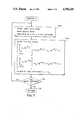
- the flow chart for performing disk backup, or tape write,is illustrated in FIG. 3.
- data bytesare read 302 from the disk into the random access memory (RAM) buffer and arranged or formatted into sixteen sectors of 1024 bytes each.
- the ENCODE subroutineis called 304 to generate or create the two error-correction code (ECC) sectors related to or corresponding to the sixteen data sectors and placed in sectors 17 and 18 of the RAM buffer. All 18 sectors, including the sixteen data sectors and the two ECC sectors, are then written 306 from the RAM buffer onto the tape as a block 10 of information.
- a decision 308is then made to determine whether all disk data has been written to the tape. If so, the backup or write function is complete 310; if not, program flow returns to block 302 wherein additional disk information is backed up onto the tape.
- FIG. 4illustrates the ENCODE subroutine utilized to generate the two ECC sectors based on the sixteen data sectors.
- the next byteis selected 402 from each of the data sectors and designated c 2 through c 17 .
- the first byteis selected from each of the 16 sectors; on the second pass, the second byte is selected from each sector; and so forth.
- the equation: ##EQU4##is then divided 404 by g(x) to produce a remainder c 1 x+c 0 .
- the coefficient c 1 and c 0are the ECC bytes and are placed in order in the two ECC sectors to correspond with the sixteen data bytes.
- a decision 406is made based on whether all 1024 data bytes in the sectors have been encoded. If so, control returns 408 to the WRITE routine; if not, flow returns to block 402 wherein the next bytes in each of the sectors are encoded.
- FIGS. 5-7illustrate the program flow wherein the information is reread from the tape and restored to the disk.
- FIG. 5illustrates the main control during the restoration or READ function and begins by reading 502 the next block of information, including sixteen data sectors and two ECC sectors, from the tape 12.
- a decision 504is made to determine whether all eighteen sectors were read. If so, flow continues to block 506 wherein the data sectors are written to the disk; if not, an attempt is made to reread 508 all unread sectors.
- the attempt to rereadcan be made "in a gulp" or using an odd/even scheme to sequentially access the odd and even sectors.
- a decision 510is made to again query whether all eighteen sectors have now been read.
- the data sectorsare written 506 to the disk; if not, a decision 512 is made to determine whether 16 or 17 sectors have been read. If so, the unread sectors can be restored using the Reed-Solomon code, which as disclosed herein will restore up to two erasures. In such a case, erasure correction is performed 514 by calling the appropriate restoration subroutine, and the data sectors are written 506 to the disk.
- a decision 516is made to determine whether twelve attempts to reread have been made. If not, another attempt to reread 508 is made; if so, a decision 518 is made to determine whether this is the first twelve tries at a reread. If so, the tape is retensioned 520 and the reread loop beginning with block 508 is reinitiated. The tape is retensioned by transporting it first to one end of the tape, then to the opposite end of the tape, and finally returning the tape to the problem block. Frequently, this retensioning of the tape will enable the sectors to be read.
- the subroutineindicates that a failure 520 has occurred and that the data from the tape cannot be recovered. As indicated above, this failure mode has not yet been encountered in rather extensive testing of the present invention. However, if such failure were encountered, extraordinary measures could be taken to read the tape; or the backup information could possibly be recovered from yet another backup media.
- FIG. 6The program flow to recover from a single erasure is illustrated in FIG. 6 and denominated RECOVER 1. Processing begins by selecting 602 the next byte from each sector read. One of the parameters passed to the RECOVER 1 subroutine is the location of the erasure, which is in the jth position. Processing continues by solving the following equation which has a single unknown--namely c j : ##EQU5##
- the polynomial g(x)has roots at q 127 and q 128 in GF(256). Because the polynomial on the left side of the above equation is a multiple of g(x), this polynomial also has roots at q 127 and q 128 .
- the summation term in the above equationis known because all of the c i 's are bytes which can be read. Additionally, since q is a known primitive root, the expression (q 127 ) i is also known. In the second term of the equation, the factor (q 127 ) j is also known. Consequently, the single equation can be solved for the single unknown c j to derive the erased coefficient or missing data byte.
- a decision 606is made to determine whether all 1024 bytes in the unreadable sector have been restored. If so, the subroutine returns 608 to block 514 in FIG. 5; if not, program flow returns to block 602 to continue the data restoration or erasure recovery.
- the RECOVER 2 subroutine for restoring two unreadable or erased sectorsis illustrated in FIG. 7.
- the subroutinebegins by selecting 702 the next byte from each of the sixteen sectors which were read.
- the READ routine(FIG. 5) advises the RECOVER 2 subroutine of the location of the erasures, which are in the jth and kth positions.
- Program flowpasses to block 704 wherein the following two equations are solved for the two unknowns c j and c k : ##EQU6##
- the first summation term of each equationcan be calculated because c i is known (i.e. has been successfully read) for all i not equal to j or k. Also, q 127 and q 128 are known.
- Source code for implementing the flow charts illustrated in FIGS. 3-7is attached hereto as appendix A.
- the source codeis written in C language and will be readily understood and appreciated by those having ordinary skill in the programming art.
- This implementationis for GF(256) generated by the polynomial:
- log f[ ]contains the primitive root logs of the ordered entries. For example, the log of the second entry, or 1, is 255; the log for the third entry, or 2, is 1; and so forth. The first entry is never accessed and therefore is arbitrarily given the value zero.
- the primitive root q of this fieldis binary 00000010.
- the look-up table "exp f[ ]"includes entries which are the powers of the primitive root q. For example, q 0 is 00000001; q 1 is 00000010; q 2 is 00000100; and so forth.
- the described system and method for encoding and storing digital information on tape, and the resulting tapecomprise a significant enhancement of the reliability and recoverability of the stored information.
- the present inventionalso results in significant efficiencies, both in speed and physical tape space.
- a Reed-Solomon codeutilizes relatively little tape space while providing full recoverability from up to two erasures in the sixteen corresponding data bytes.
Landscapes
- Engineering & Computer Science (AREA)
- Signal Processing (AREA)
- General Engineering & Computer Science (AREA)
- Multimedia (AREA)
- Signal Processing For Digital Recording And Reproducing (AREA)
- Error Detection And Correction (AREA)
Abstract
Description
q.sup.2k+1 =1
g(x)=x.sup.2 -q.sup.69 x+1
g(x)=x.sup.2 +q.sup.69 x+1
f(x)=x.sup.8 +x.sup.6 +x.sup.5 +x+1
Claims (20)
Priority Applications (7)
| Application Number | Priority Date | Filing Date | Title |
|---|---|---|---|
| US06/830,559US4796110A (en) | 1986-02-18 | 1986-02-18 | System and method for encoding and storing digital information on magnetic tape |
| AU67841/87AAU6784187A (en) | 1986-02-18 | 1987-01-20 | Storing digital information |
| IE870226AIE870226L (en) | 1986-02-18 | 1987-01-29 | Encoding and storing digital information on magnetic tape |
| BR8700714ABR8700714A (en) | 1986-02-18 | 1987-02-17 | PROCESS OF STORAGE OF DIGITAL DATA WORDS IN A MAGNETIC MEDIA, PROCESS OF STORAGE OF DATA WORDS IN A MAGNETIC MEDIA AND MAGNETIC TAPE |
| KR1019870001277AKR910005557B1 (en) | 1986-02-18 | 1987-02-17 | System and method for encoding and storing digital information on magnetic tape |
| EP87301389AEP0234849A3 (en) | 1986-02-18 | 1987-02-18 | Method of encoding digital information on magnetic tape |
| JP62035431AJPS62192984A (en) | 1986-02-18 | 1987-02-18 | Method and apparatus for storing digital data word |
Applications Claiming Priority (1)
| Application Number | Priority Date | Filing Date | Title |
|---|---|---|---|
| US06/830,559US4796110A (en) | 1986-02-18 | 1986-02-18 | System and method for encoding and storing digital information on magnetic tape |
Publications (1)
| Publication Number | Publication Date |
|---|---|
| US4796110Atrue US4796110A (en) | 1989-01-03 |
Family
ID=25257208
Family Applications (1)
| Application Number | Title | Priority Date | Filing Date |
|---|---|---|---|
| US06/830,559Expired - LifetimeUS4796110A (en) | 1986-02-18 | 1986-02-18 | System and method for encoding and storing digital information on magnetic tape |
Country Status (7)
| Country | Link |
|---|---|
| US (1) | US4796110A (en) |
| EP (1) | EP0234849A3 (en) |
| JP (1) | JPS62192984A (en) |
| KR (1) | KR910005557B1 (en) |
| AU (1) | AU6784187A (en) |
| BR (1) | BR8700714A (en) |
| IE (1) | IE870226L (en) |
Cited By (21)
| Publication number | Priority date | Publication date | Assignee | Title |
|---|---|---|---|---|
| US4852099A (en)* | 1987-02-06 | 1989-07-25 | Sony Corporation | Error correction method using Reed-Solomon code |
| US4958337A (en)* | 1986-02-20 | 1990-09-18 | Sharp Kabushiki Kaisha | Disk recording checking method for determining if a disk is defective by the number of errors present |
| US5067131A (en)* | 1987-10-27 | 1991-11-19 | Sony Corporation | Apparatus and method for recording and/or reproducing a digital signal |
| US5122913A (en)* | 1988-12-29 | 1992-06-16 | Sharp Kabushiki Kaisha | Data recording/reproducing apparatus with error detection and data re-recording |
| US5157670A (en)* | 1989-12-04 | 1992-10-20 | Avasem Corporation | Error correction code interruption system |
| US5182679A (en)* | 1989-03-08 | 1993-01-26 | Hitachi, Ltd. | Information recording/reproducing method and magnetic tape subsystem employing the same |
| US5204708A (en)* | 1991-12-20 | 1993-04-20 | Eastman Kodak Company | Method and apparatus for magnetically communicating via a photographic filmstrip with enhanced reliability |
| US5222086A (en)* | 1989-12-29 | 1993-06-22 | Laboratoire Europeen De Recherches Electroniques Avancees Societe En Nom Collectif | Method for the linking of data during the recording of encoded data on a recordable type optical disk |
| US5263030A (en)* | 1991-02-13 | 1993-11-16 | Digital Equipment Corporation | Method and apparatus for encoding data for storage on magnetic tape |
| US5327305A (en)* | 1992-08-14 | 1994-07-05 | Conner Peripherals, Inc. | Tape format detection system |
| US5335328A (en)* | 1989-06-28 | 1994-08-02 | International Business Machines Corporation | Methods for recording and reading data from a record member having data in any one of a plurality of block formats including determining length of records being transferred |
| US5369652A (en)* | 1993-06-14 | 1994-11-29 | International Business Machines Corporation | Error detection and correction having one data format recordable on record media using a diverse number of concurrently recorded tracks |
| US5461486A (en)* | 1992-12-04 | 1995-10-24 | Matsushita Electric Industrial Co., Ltd. | Apparatus for recording and reproducing digital video signal |
| US5737344A (en)* | 1995-05-25 | 1998-04-07 | International Business Machines Corporation | Digital data storage with increased robustness against data loss |
| US6148430A (en)* | 1998-05-15 | 2000-11-14 | Quantum Corporation | Encoding apparatus for RAID-6 system and tape drives |
| US6172833B1 (en) | 1998-08-05 | 2001-01-09 | International Business Machines Corporation | Retrieval of serpentine pattern data using a memory device of a tape cartridge |
| EP1109320A1 (en)* | 1999-12-17 | 2001-06-20 | Micronas GmbH | Device for converting data for a Reed-Solomon decoder |
| US6349356B2 (en) | 1997-12-10 | 2002-02-19 | International Business Machines Corporation | Host-available device block map for optimized file retrieval from serpentine tape drives |
| US20040172506A1 (en)* | 2001-10-23 | 2004-09-02 | Hitachi, Ltd. | Storage control system |
| US6967802B1 (en)* | 2002-05-15 | 2005-11-22 | Storage Technology Corporation | System and method for reducing latency for serially accessible media |
| WO2012064691A3 (en)* | 2010-11-08 | 2012-12-27 | Jbi Inc. | System and method for reading a magnetic tape |
Families Citing this family (2)
| Publication number | Priority date | Publication date | Assignee | Title |
|---|---|---|---|---|
| US4899232A (en)* | 1987-04-07 | 1990-02-06 | Sony Corporation | Apparatus for recording and/or reproducing digital data information |
| KR101927285B1 (en)* | 2016-12-09 | 2018-12-11 | 주식회사 비엠지코리아 | apparatus for regulating angle and manufacturing apparatus for duct comprising the same |
Citations (9)
| Publication number | Priority date | Publication date | Assignee | Title |
|---|---|---|---|---|
| US3745528A (en)* | 1971-12-27 | 1973-07-10 | Ibm | Error correction for two tracks in a multitrack system |
| US3911402A (en)* | 1974-06-03 | 1975-10-07 | Digital Equipment Corp | Diagnostic circuit for data processing system |
| US4413339A (en)* | 1981-06-24 | 1983-11-01 | Digital Equipment Corporation | Multiple error detecting and correcting system employing Reed-Solomon codes |
| US4468712A (en)* | 1981-07-02 | 1984-08-28 | Irwin International, Inc. | Positioner apparatus for tape recorder heads |
| US4472750A (en)* | 1981-07-02 | 1984-09-18 | Irwin Magnetic Systems, Inc. | Data record with pre-recorded transducer positioning signals, and system for utilizing same |
| US4593394A (en)* | 1982-09-30 | 1986-06-03 | Nec Corporation | Method capable of simultaneously decoding two reproduced sequences |
| US4607367A (en)* | 1983-07-19 | 1986-08-19 | Sony Corporation | Correcting errors in binary data |
| US4637021A (en)* | 1983-09-28 | 1987-01-13 | Pioneer Electronic Corporation | Multiple pass error correction |
| US4646303A (en)* | 1983-10-05 | 1987-02-24 | Nippon Gakki Seizo Kabushiki Kaisha | Data error detection and correction circuit |
Family Cites Families (7)
| Publication number | Priority date | Publication date | Assignee | Title |
|---|---|---|---|---|
| US4375100A (en)* | 1979-10-24 | 1983-02-22 | Matsushita Electric Industrial Company, Limited | Method and apparatus for encoding low redundancy check words from source data |
| JPS56143509A (en)* | 1980-04-10 | 1981-11-09 | Mitsubishi Electric Corp | Recording method for multichannel voice pcm signal |
| JPS5849923A (en)* | 1981-08-24 | 1983-03-24 | Seiko Koki Kk | Electronic shutter for automatic dimming strobe |
| GB2124806B (en)* | 1982-08-06 | 1986-05-14 | Sony Corp | Method of correcting errors in binary data |
| JPS60154371A (en)* | 1984-01-24 | 1985-08-14 | Toshiba Corp | Digital signal error detection method |
| JPH0770177B2 (en)* | 1984-01-25 | 1995-07-31 | 株式会社日立製作所 | Digital signal reproducing device |
| US4586094A (en)* | 1984-03-13 | 1986-04-29 | Irwin Magnetic Systems, Inc. | Method and apparatus for pre-recording tracking information on magnetic media |
- 1986
- 1986-02-18USUS06/830,559patent/US4796110A/ennot_activeExpired - Lifetime
- 1987
- 1987-01-20AUAU67841/87Apatent/AU6784187A/ennot_activeAbandoned
- 1987-01-29IEIE870226Apatent/IE870226L/enunknown
- 1987-02-17BRBR8700714Apatent/BR8700714A/enunknown
- 1987-02-17KRKR1019870001277Apatent/KR910005557B1/ennot_activeExpired
- 1987-02-18EPEP87301389Apatent/EP0234849A3/ennot_activeWithdrawn
- 1987-02-18JPJP62035431Apatent/JPS62192984A/enactivePending
Patent Citations (9)
| Publication number | Priority date | Publication date | Assignee | Title |
|---|---|---|---|---|
| US3745528A (en)* | 1971-12-27 | 1973-07-10 | Ibm | Error correction for two tracks in a multitrack system |
| US3911402A (en)* | 1974-06-03 | 1975-10-07 | Digital Equipment Corp | Diagnostic circuit for data processing system |
| US4413339A (en)* | 1981-06-24 | 1983-11-01 | Digital Equipment Corporation | Multiple error detecting and correcting system employing Reed-Solomon codes |
| US4468712A (en)* | 1981-07-02 | 1984-08-28 | Irwin International, Inc. | Positioner apparatus for tape recorder heads |
| US4472750A (en)* | 1981-07-02 | 1984-09-18 | Irwin Magnetic Systems, Inc. | Data record with pre-recorded transducer positioning signals, and system for utilizing same |
| US4593394A (en)* | 1982-09-30 | 1986-06-03 | Nec Corporation | Method capable of simultaneously decoding two reproduced sequences |
| US4607367A (en)* | 1983-07-19 | 1986-08-19 | Sony Corporation | Correcting errors in binary data |
| US4637021A (en)* | 1983-09-28 | 1987-01-13 | Pioneer Electronic Corporation | Multiple pass error correction |
| US4646303A (en)* | 1983-10-05 | 1987-02-24 | Nippon Gakki Seizo Kabushiki Kaisha | Data error detection and correction circuit |
Non-Patent Citations (10)
| Title |
|---|
| Blahut, Theory and Practice of Error Control Codes , pp. 174 175 (Addison Wesley 1983).* |
| Blahut, Theory and Practice of Error Control Codes, pp. 174-175 (Addison-Wesley 1983). |
| Reed, Polynomial Codes Over Certain Finite Fields , 8 J. Soc. Indust. Appl. Math. 300 (1960).* |
| Reed, Polynomial Codes Over Certain Finite Fields, 8 J. Soc. Indust. Appl. Math. 300 (1960). |
| Technical Support Package on Fast Reed Solomon Decoder for Fall 1985 , NASA Tech Brief vol. 9, No. 3, Item 34 from Jet Propulsion Laboratory Invention Report NPO 15867/5326 (Sep. 1985).* |
| Technical Support Package on Fast Reed-Solomon Decoder for Fall 1985, NASA Tech Brief vol. 9, No. 3, Item #34 from Jet Propulsion Laboratory Invention Report NPO-15867/5326 (Sep. 1985). |
| Technical Support Package on Modular VLSI Reed Solomon Decoder for Fall 1985 , NASA Tech Brief vol. 9, No. 3, Item 51 from Jet Propulsion Laboratory Invention Report NPO 15837/5292 (Sep. 1985).* |
| Technical Support Package on Modular VLSI Reed-Solomon Decoder for Fall 1985, NASA Tech Brief vol. 9, No. 3, Item #51 from Jet Propulsion Laboratory Invention Report NPO-15837/5292 (Sep. 1985). |
| Technical Support Package on Systolic VLSI Reed Solomon Decoder for Fall 1985 , NASA Tech Brief vol. 9, No. 3, Item 110 from Jet Propulsion Laboratory Invention Report NPO 16383/5857 (Sep. 1985).* |
| Technical Support Package on Systolic VLSI Reed-Solomon Decoder for Fall 1985, NASA Tech Brief vol. 9, No. 3, Item #110 from Jet Propulsion Laboratory Invention Report NPO-16383/5857 (Sep. 1985). |
Cited By (23)
| Publication number | Priority date | Publication date | Assignee | Title |
|---|---|---|---|---|
| US4958337A (en)* | 1986-02-20 | 1990-09-18 | Sharp Kabushiki Kaisha | Disk recording checking method for determining if a disk is defective by the number of errors present |
| US4852099A (en)* | 1987-02-06 | 1989-07-25 | Sony Corporation | Error correction method using Reed-Solomon code |
| US5067131A (en)* | 1987-10-27 | 1991-11-19 | Sony Corporation | Apparatus and method for recording and/or reproducing a digital signal |
| US5122913A (en)* | 1988-12-29 | 1992-06-16 | Sharp Kabushiki Kaisha | Data recording/reproducing apparatus with error detection and data re-recording |
| US5182679A (en)* | 1989-03-08 | 1993-01-26 | Hitachi, Ltd. | Information recording/reproducing method and magnetic tape subsystem employing the same |
| US5335328A (en)* | 1989-06-28 | 1994-08-02 | International Business Machines Corporation | Methods for recording and reading data from a record member having data in any one of a plurality of block formats including determining length of records being transferred |
| US5157670A (en)* | 1989-12-04 | 1992-10-20 | Avasem Corporation | Error correction code interruption system |
| US5222086A (en)* | 1989-12-29 | 1993-06-22 | Laboratoire Europeen De Recherches Electroniques Avancees Societe En Nom Collectif | Method for the linking of data during the recording of encoded data on a recordable type optical disk |
| US5263030A (en)* | 1991-02-13 | 1993-11-16 | Digital Equipment Corporation | Method and apparatus for encoding data for storage on magnetic tape |
| US5204708A (en)* | 1991-12-20 | 1993-04-20 | Eastman Kodak Company | Method and apparatus for magnetically communicating via a photographic filmstrip with enhanced reliability |
| US5327305A (en)* | 1992-08-14 | 1994-07-05 | Conner Peripherals, Inc. | Tape format detection system |
| US5461486A (en)* | 1992-12-04 | 1995-10-24 | Matsushita Electric Industrial Co., Ltd. | Apparatus for recording and reproducing digital video signal |
| US5369652A (en)* | 1993-06-14 | 1994-11-29 | International Business Machines Corporation | Error detection and correction having one data format recordable on record media using a diverse number of concurrently recorded tracks |
| US5737344A (en)* | 1995-05-25 | 1998-04-07 | International Business Machines Corporation | Digital data storage with increased robustness against data loss |
| US6349356B2 (en) | 1997-12-10 | 2002-02-19 | International Business Machines Corporation | Host-available device block map for optimized file retrieval from serpentine tape drives |
| US6148430A (en)* | 1998-05-15 | 2000-11-14 | Quantum Corporation | Encoding apparatus for RAID-6 system and tape drives |
| US6172833B1 (en) | 1998-08-05 | 2001-01-09 | International Business Machines Corporation | Retrieval of serpentine pattern data using a memory device of a tape cartridge |
| EP1109320A1 (en)* | 1999-12-17 | 2001-06-20 | Micronas GmbH | Device for converting data for a Reed-Solomon decoder |
| US20040172506A1 (en)* | 2001-10-23 | 2004-09-02 | Hitachi, Ltd. | Storage control system |
| US6981118B2 (en)* | 2001-10-23 | 2005-12-27 | Hitachi, Ltd. | Storage control system |
| US6967802B1 (en)* | 2002-05-15 | 2005-11-22 | Storage Technology Corporation | System and method for reducing latency for serially accessible media |
| WO2012064691A3 (en)* | 2010-11-08 | 2012-12-27 | Jbi Inc. | System and method for reading a magnetic tape |
| US9196296B2 (en) | 2010-11-08 | 2015-11-24 | Jbi Inc | System and method for reading a magnetic tape |
Also Published As
| Publication number | Publication date |
|---|---|
| EP0234849A2 (en) | 1987-09-02 |
| KR910005557B1 (en) | 1991-07-31 |
| IE870226L (en) | 1987-08-18 |
| EP0234849A3 (en) | 1989-11-15 |
| AU6784187A (en) | 1987-08-20 |
| BR8700714A (en) | 1987-12-08 |
| JPS62192984A (en) | 1987-08-24 |
| KR870008278A (en) | 1987-09-25 |
Similar Documents
| Publication | Publication Date | Title |
|---|---|---|
| US4796110A (en) | System and method for encoding and storing digital information on magnetic tape | |
| US4564945A (en) | Error-correction code for digital data on video disc | |
| US7191382B2 (en) | Methods and apparatus for correcting data and error detection codes on the fly | |
| US6661591B1 (en) | Disk drive employing sector-reconstruction-interleave sectors each storing redundancy data generated in response to an interleave of data sectors | |
| JP3405712B2 (en) | Data recovery method and data storage device | |
| US6687850B1 (en) | Disk drive for storing sector-reconstruction sectors and for storing a sector-reconstruction status in sectors distributed around a disk | |
| US4949342A (en) | Code error detecting method | |
| US5629949A (en) | Error correction verification method and apparatus using CRC check remainders | |
| US5757824A (en) | Code error correction apparatus | |
| US6891690B2 (en) | On-drive integrated sector format raid error correction code system and method | |
| US6367047B1 (en) | Multi-level error detection and correction technique for data storage recording device | |
| US9229813B2 (en) | Error correction with on-demand parity sectors in magnetic data storage devices | |
| US5737344A (en) | Digital data storage with increased robustness against data loss | |
| US9286159B2 (en) | Track-band squeezed-sector error correction in magnetic data storage devices | |
| CN101458947B (en) | Recording/reproducing apparatus and recording/reproducing method | |
| EP0335529B1 (en) | Method and apparatus for encoding and mapping magnetic disk sector addresses | |
| US6877128B2 (en) | Weighted error/erasure correction in a multi-track storage medium | |
| US5265104A (en) | Data storage system including redundant storage devices | |
| US4847705A (en) | Method and apparatus for encoding magnetic disk sector addresses | |
| US6044487A (en) | Majority voting scheme for hard error sites | |
| US6769088B1 (en) | Sector-coding technique for reduced read-after-write operations | |
| US4989211A (en) | Sector mis-synchronization detection method | |
| US7131052B2 (en) | Algebraic decoder and method for correcting an arbitrary mixture of burst and random errors | |
| US6128760A (en) | Method and apparatus for calculating a CRC remainder | |
| CA1208794A (en) | Error detection system |
Legal Events
| Date | Code | Title | Description |
|---|---|---|---|
| AS | Assignment | Owner name:IRWIN MAGNETIC SYSTEMS, INC. 2311 GREEN ROAD ANN A Free format text:ASSIGNMENT OF ASSIGNORS INTEREST.;ASSIGNORS:GLASS, EDWARD N.;STARK, WAYNE;REEL/FRAME:004519/0174 Effective date:19860213 Owner name:IRWIN MAGNETIC SYSTEMS, INC., A CORP. OF MICIGAN,M Free format text:ASSIGNMENT OF ASSIGNORS INTEREST;ASSIGNORS:GLASS, EDWARD N.;STARK, WAYNE;REEL/FRAME:004519/0174 Effective date:19860213 | |
| STCF | Information on status: patent grant | Free format text:PATENTED CASE | |
| AS | Assignment | Owner name:BARCLAYS BANK PLC Free format text:SECURITY INTEREST;ASSIGNOR:IRWIN MAGNETIC SYSTEMS, INC.;REEL/FRAME:005281/0484 Effective date:19900424 | |
| FEPP | Fee payment procedure | Free format text:PAT HLDR NO LONGER CLAIMS SMALL ENT STAT AS SMALL BUSINESS (ORIGINAL EVENT CODE: LSM2); ENTITY STATUS OF PATENT OWNER: LARGE ENTITY Free format text:PAYOR NUMBER ASSIGNED (ORIGINAL EVENT CODE: ASPN); ENTITY STATUS OF PATENT OWNER: LARGE ENTITY | |
| AS | Assignment | Owner name:IRWIN MAGNETIC SYSTEMS, INC. A CORPORATION OF DE Free format text:MERGER;ASSIGNOR:IRWIN MAGNETIC SYSTEMS, INC., A CORPORATION OF MI (MERGED INTO);REEL/FRAME:006073/0871 Effective date:19920325 | |
| AS | Assignment | Owner name:ARCHIVE CORPORATION, A DE CORP., CALIFORNIA Free format text:NUNC PRO TUNC ASSIGNMENT;ASSIGNOR:IRWIN MAGNETIC SYSTEMS, INC., A DE CORP.;REEL/FRAME:006139/0340 Effective date:19920430 | |
| FPAY | Fee payment | Year of fee payment:4 | |
| AS | Assignment | Owner name:ARCHIVE CORPORATION, CALIFORNIA Free format text:RELEASE BY SECURED PARTY;ASSIGNOR:BARCLAYS BANK PLC, AS COLLATERAL AGENT;REEL/FRAME:006690/0219 Effective date:19921223 | |
| FEPP | Fee payment procedure | Free format text:PAYER NUMBER DE-ASSIGNED (ORIGINAL EVENT CODE: RMPN); ENTITY STATUS OF PATENT OWNER: LARGE ENTITY Free format text:PAYOR NUMBER ASSIGNED (ORIGINAL EVENT CODE: ASPN); ENTITY STATUS OF PATENT OWNER: LARGE ENTITY | |
| FPAY | Fee payment | Year of fee payment:8 | |
| AS | Assignment | Owner name:SEAGATE TECHNOLOGY, INC., CALIFORNIA Free format text:MERGER;ASSIGNOR:SEAGATE PERIPHERALS,INC.;REEL/FRAME:008587/0277 Effective date:19970115 Owner name:SEAGATE PERIPHERALS, INC., CALIFORNIA Free format text:CHANGE OF NAME;ASSIGNOR:CONNER PERIPHERALS, INC.;REEL/FRAME:008568/0400 Effective date:19960228 | |
| AS | Assignment | Owner name:SEAGATE PERIPHERALS, INC., CALIFORNIA Free format text:;ASSIGNOR:CONNER PERIPHERALS, INC.;REEL/FRAME:008545/0682 Effective date:19960228 | |
| FPAY | Fee payment | Year of fee payment:12 | |
| AS | Assignment | Owner name:SEAGATE REMOVABLE STORAGE SOLUTIONS LLC, CALIFORNI Free format text:ASSIGNMENT OF ASSIGNORS INTEREST;ASSIGNOR:SEAGATE TECHNOLOGY, INC.;REEL/FRAME:011111/0459 Effective date:20000728 | |
| AS | Assignment | Owner name:CHASE MANHATTAN BANK, AS COLLATERAL AGENT, THE, NE Free format text:SECURITY AGREEMENT;ASSIGNOR:SEAGATE REMOVABLE STORAGE SOLUTIONS LLC;REEL/FRAME:011436/0001 Effective date:20001122 | |
| AS | Assignment | Owner name:CERTANCE LLC (FORMERLY SEAGATE REMOVABLE STORAGE S Free format text:RELEASE;ASSIGNOR:JPMORGAN CHASE BANK;REEL/FRAME:015918/0321 Effective date:20041101 |