US4795473A - Extramedullary femoral head-neck prosthesis and method of implanting same - Google Patents
Extramedullary femoral head-neck prosthesis and method of implanting sameDownload PDFInfo
- Publication number
- US4795473A US4795473AUS07/001,827US182787AUS4795473AUS 4795473 AUS4795473 AUS 4795473AUS 182787 AUS182787 AUS 182787AUS 4795473 AUS4795473 AUS 4795473A
- Authority
- US
- United States
- Prior art keywords
- neck
- barrel
- femur
- stem
- prosthesis
- Prior art date
- Legal status (The legal status is an assumption and is not a legal conclusion. Google has not performed a legal analysis and makes no representation as to the accuracy of the status listed.)
- Expired - Lifetime
Links
Images

Classifications
- A—HUMAN NECESSITIES
- A61—MEDICAL OR VETERINARY SCIENCE; HYGIENE
- A61B—DIAGNOSIS; SURGERY; IDENTIFICATION
- A61B17/00—Surgical instruments, devices or methods
- A61B17/56—Surgical instruments or methods for treatment of bones or joints; Devices specially adapted therefor
- A61B17/58—Surgical instruments or methods for treatment of bones or joints; Devices specially adapted therefor for osteosynthesis, e.g. bone plates, screws or setting implements
- A61B17/68—Internal fixation devices, including fasteners and spinal fixators, even if a part thereof projects from the skin
- A61B17/74—Devices for the head or neck or trochanter of the femur
- A61B17/742—Devices for the head or neck or trochanter of the femur having one or more longitudinal elements oriented along or parallel to the axis of the neck
- A61B17/746—Devices for the head or neck or trochanter of the femur having one or more longitudinal elements oriented along or parallel to the axis of the neck the longitudinal elements coupled to a plate opposite the femoral head
- A—HUMAN NECESSITIES
- A61—MEDICAL OR VETERINARY SCIENCE; HYGIENE
- A61B—DIAGNOSIS; SURGERY; IDENTIFICATION
- A61B17/00—Surgical instruments, devices or methods
- A61B17/14—Surgical saws
- A61B17/15—Guides therefor
- A—HUMAN NECESSITIES
- A61—MEDICAL OR VETERINARY SCIENCE; HYGIENE
- A61B—DIAGNOSIS; SURGERY; IDENTIFICATION
- A61B17/00—Surgical instruments, devices or methods
- A61B17/16—Instruments for performing osteoclasis; Drills or chisels for bones; Trepans
- A61B17/17—Guides or aligning means for drills, mills, pins or wires
- A61B17/1739—Guides or aligning means for drills, mills, pins or wires specially adapted for particular parts of the body
- A61B17/1742—Guides or aligning means for drills, mills, pins or wires specially adapted for particular parts of the body for the hip
- A61B17/175—Guides or aligning means for drills, mills, pins or wires specially adapted for particular parts of the body for the hip for preparing the femur for hip prosthesis insertion
- A—HUMAN NECESSITIES
- A61—MEDICAL OR VETERINARY SCIENCE; HYGIENE
- A61F—FILTERS IMPLANTABLE INTO BLOOD VESSELS; PROSTHESES; DEVICES PROVIDING PATENCY TO, OR PREVENTING COLLAPSING OF, TUBULAR STRUCTURES OF THE BODY, e.g. STENTS; ORTHOPAEDIC, NURSING OR CONTRACEPTIVE DEVICES; FOMENTATION; TREATMENT OR PROTECTION OF EYES OR EARS; BANDAGES, DRESSINGS OR ABSORBENT PADS; FIRST-AID KITS
- A61F2/00—Filters implantable into blood vessels; Prostheses, i.e. artificial substitutes or replacements for parts of the body; Appliances for connecting them with the body; Devices providing patency to, or preventing collapsing of, tubular structures of the body, e.g. stents
- A61F2/02—Prostheses implantable into the body
- A61F2/30—Joints
- A61F2/32—Joints for the hip
- A61F2/36—Femoral heads ; Femoral endoprostheses
- A61F2/3601—Femoral heads ; Femoral endoprostheses for replacing only the epiphyseal or metaphyseal parts of the femur, e.g. endoprosthetic femoral heads or necks directly fixed to the natural femur by internal fixation devices
- A—HUMAN NECESSITIES
- A61—MEDICAL OR VETERINARY SCIENCE; HYGIENE
- A61F—FILTERS IMPLANTABLE INTO BLOOD VESSELS; PROSTHESES; DEVICES PROVIDING PATENCY TO, OR PREVENTING COLLAPSING OF, TUBULAR STRUCTURES OF THE BODY, e.g. STENTS; ORTHOPAEDIC, NURSING OR CONTRACEPTIVE DEVICES; FOMENTATION; TREATMENT OR PROTECTION OF EYES OR EARS; BANDAGES, DRESSINGS OR ABSORBENT PADS; FIRST-AID KITS
- A61F2/00—Filters implantable into blood vessels; Prostheses, i.e. artificial substitutes or replacements for parts of the body; Appliances for connecting them with the body; Devices providing patency to, or preventing collapsing of, tubular structures of the body, e.g. stents
- A61F2/02—Prostheses implantable into the body
- A61F2/30—Joints
- A61F2/46—Special tools for implanting artificial joints
- A61F2/4684—Trial or dummy prostheses
- A—HUMAN NECESSITIES
- A61—MEDICAL OR VETERINARY SCIENCE; HYGIENE
- A61F—FILTERS IMPLANTABLE INTO BLOOD VESSELS; PROSTHESES; DEVICES PROVIDING PATENCY TO, OR PREVENTING COLLAPSING OF, TUBULAR STRUCTURES OF THE BODY, e.g. STENTS; ORTHOPAEDIC, NURSING OR CONTRACEPTIVE DEVICES; FOMENTATION; TREATMENT OR PROTECTION OF EYES OR EARS; BANDAGES, DRESSINGS OR ABSORBENT PADS; FIRST-AID KITS
- A61F2/00—Filters implantable into blood vessels; Prostheses, i.e. artificial substitutes or replacements for parts of the body; Appliances for connecting them with the body; Devices providing patency to, or preventing collapsing of, tubular structures of the body, e.g. stents
- A61F2/02—Prostheses implantable into the body
- A61F2/30—Joints
- A61F2/32—Joints for the hip
- A61F2/36—Femoral heads ; Femoral endoprostheses
- A61F2/3609—Femoral heads or necks; Connections of endoprosthetic heads or necks to endoprosthetic femoral shafts
- A61F2002/3625—Necks
- A61F2002/3631—Necks with an integral complete or partial peripheral collar or bearing shoulder at its base
- A—HUMAN NECESSITIES
- A61—MEDICAL OR VETERINARY SCIENCE; HYGIENE
- A61F—FILTERS IMPLANTABLE INTO BLOOD VESSELS; PROSTHESES; DEVICES PROVIDING PATENCY TO, OR PREVENTING COLLAPSING OF, TUBULAR STRUCTURES OF THE BODY, e.g. STENTS; ORTHOPAEDIC, NURSING OR CONTRACEPTIVE DEVICES; FOMENTATION; TREATMENT OR PROTECTION OF EYES OR EARS; BANDAGES, DRESSINGS OR ABSORBENT PADS; FIRST-AID KITS
- A61F2/00—Filters implantable into blood vessels; Prostheses, i.e. artificial substitutes or replacements for parts of the body; Appliances for connecting them with the body; Devices providing patency to, or preventing collapsing of, tubular structures of the body, e.g. stents
- A61F2/02—Prostheses implantable into the body
- A61F2/30—Joints
- A61F2/32—Joints for the hip
- A61F2/36—Femoral heads ; Femoral endoprostheses
- A61F2/3609—Femoral heads or necks; Connections of endoprosthetic heads or necks to endoprosthetic femoral shafts
- A61F2002/365—Connections of heads to necks
- Y—GENERAL TAGGING OF NEW TECHNOLOGICAL DEVELOPMENTS; GENERAL TAGGING OF CROSS-SECTIONAL TECHNOLOGIES SPANNING OVER SEVERAL SECTIONS OF THE IPC; TECHNICAL SUBJECTS COVERED BY FORMER USPC CROSS-REFERENCE ART COLLECTIONS [XRACs] AND DIGESTS
- Y10—TECHNICAL SUBJECTS COVERED BY FORMER USPC
- Y10S—TECHNICAL SUBJECTS COVERED BY FORMER USPC CROSS-REFERENCE ART COLLECTIONS [XRACs] AND DIGESTS
- Y10S623/00—Prosthesis, i.e. artificial body members, parts thereof, or aids and accessories therefor
- Y10S623/902—Method of implanting
- Y10S623/908—Bone
Definitions
- This inventionrelates generally to the art of femoral prosthetics, and more particularly to an improved femoral head-neck prosthesis and a method of implanting such a prosthesis.
- intramedullary femoral head-neck implantsi.e., implants having a long stem secured in the medullary (marrow) canal of the femur, may cause deterioration of the femur since the proximal (upper) end of the femur is shielded from normal stress.
- an intramedullary prosthesishas a relatively short expected lifespan, at least relative to the expected lifespan of younger patients.
- patients having intramedullary implantsmust reduce their activity substantially.
- the Huggler prosthesisincludes a tension or tie rod through the bone, a pressure disc in contact with the femoral neck and a counter plate at the lateral side of the femur.
- One of the advantages of this kind of prosthesisis that there is sufficient supporting bone for an intramedullary implant if it becomes necessary to replace it.
- Huggler's approachincludes positioning the thrust plate perpendicular to the longitudinal axis of the femoral neck and the tie rod along the longitudinal axis of the femoral neck (e.g., approximately 35 degrees from horizontal). According to Huggler, positioning the tie rod along the central longitudinal axis of the femoral neck is desirable to prevent motion of the tie rod relative to the bone and counter plate. More specifically, Huggler's position is that the more vertical the tie rod, the more the distal end of the tie rod will move within the counter plate (i.e., the greater the "micromotion").
- the tie rod of the Huggler prosthesisis aligned with the central longitudinal axis of the femoral neck, the tie rod is not aligned (or near alignment) with the generally vertical load on the femur caused by normal activity, such as walking.
- the tie rodis subjected to a bending moment, which may lead to its fracture. This may have been a contributing cause to the tie rod fracture discussed in Thrust-Plate Prosthesis, at p. 127.
- the Huggler prosthesisis anchored relatively high (proximal) on the lateral side of the femoral shaft where the cortical bone is relatively thin. This may be the reason that one-third of the patients treated with the prosthesis complained of pain in the first 6-8 months (Final Results, at p. 130), the pain apparently abating when the cortical bone has thickened sufficiently according to Wolff's law. Another cause of this pain may be the combination of the high position of the counter plate with its relatively high profile, which may cause irritation of muscles and tendons.
- a femoral head-neck prosthesiswhich loads the femur in a manner similar to the original femoral head and neck thereby minimizing deterioration of the femur; the provision of such a prosthesis which protects the femur from movement of a replacement ball and ball stem relative to the femur as the femur is loaded and unloaded; the provision of such a prosthesis which allows a more normal lifestyle for a person in which it is installed; the provision of such a prosthesis which reduces the pain suffered by a person in which it is installed; and the provision of such a prosthesis that is durable, economical and long-lasting.
- Additional objects which may be notedinclude the provision of a method of installing such a prosthesis which reduces complications and mistakes during installation; the provision of such a method which facilitates the proper alignment of the prosthesis; the provision of such a method which causes a minimum of trauma to a patient; the provision of such a method which allows installation with only a minimum of trial-and-error; and the provision of such a method which reduces the chances of undue heat build-up caused by friction, especially while cutting and drilling the femur, since excessive heat can kill bone cells.
- an extramedullary femoral head-neck prosthesis of the present inventionis implanted in a femur.
- the femurhas a shaft and a neck at the upper end of the shaft at the medial side of the femur.
- the prosthesiscomprises a sideplate and means for securing the sideplate to the femur shaft at the lateral side of the femur.
- a barrelextends obliquely upwardly from the sideplate and has an open upper end. The barrel is adapted to be inserted in a bore extending obliquely upwardly through the shaft of the femur from the lateral side of the shaft to the neck of femur.
- the prosthesisincludes a ball assembly comprising a ball stem adapted to be inserted coaxially into the barrel through the open upper end of the barrel and to be slideably received therein.
- the ball stemis sized for a relatively close clearance fit in the barrel.
- a neckis provided at the upper end of the stem, and is adapted for face-to-face engagement with the neck of the femur.
- a ballis mounted on the neck.
- Retainer meansis provided for holding the ball stem against upward movement of the stem in the barrel.
- a method of this inventioninvolves implanting the extramedullary femoral head-neck prosthesis in the femur, the latter having a shaft and a neck at the upper end of the shaft at the medial side of the femur.
- the methodincludes cutting the neck of the femur to form a generally planar surface, and drilling a bore through the shaft of the femur to extend obliquely from the neck of the femur down to the lateral side of the shaft at an angle of approximately 30° with respect to the central longitudinal axis of the femur shaft.
- a barrel having an open endis inserted into the bore with the open end of the barrel facing upwardly and secured in fixed position in the bore.
- a stem of a ball assemblyis inserted coaxially into the barrel to bring a generally planar surface of the ball assembly into face-to-face engagement with the planar surface of the femur neck.
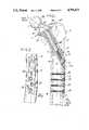
- FIG. 1is a vertical cross-sectional view through a femoral head-neck prosthesis of the present invention as installed on a femur;
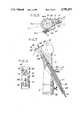
- FIG. 2is a partial side elevation of the prosthesis of FIG. 1 showing a sideplate for securing the prosthesis to the femur;
- FIG. 3is a view similar to FIG. 2, showing a sideplate of another embodiment of a femoral head-neck prosthesis of the present invention
- FIG. 4is a side view of a device used in the method of the present invention holding a saw guide for cutting of the femoral neck;
- FIG. 5is a cross-sectional view along line 5--5 of FIG. 4
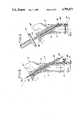
- FIG. 6is a side view of the device of FIG. 4 holding other accessories used in the method of the present invention.
- FIG. 7is a side view of the holding device of FIGS. 4-6 showing the femur being reamed
- FIG. 8is a side view of the sideplate and barrel of the prosthesis of FIG. 1 being positioned on the femur;
- FIG. 9is a front elevation of a femur being planed according to the method of the present invention.
- an extramedullary femoral head-neck prosthesis of the present inventionis designated in its entirety by the reference numeral 1.
- the femoral head-neck prosthesisis designed for implantation in a femur generally designated 3 having a shaft 5 and a neck 7 at the upper end of the shaft at the medial side of the femur.
- the femurincludes hard layer of cortical bone 9 adjacent the surface of the bone and relatively soft cancerous bone 11 inside the femur.
- the prosthesis 1generally comprises a sideplate in the form of an elongate member 13 and a barrel 15 integral with, and extending obliquely upwardly from, the sideplate.
- the barrel 15has an open upper end 17, which is inserted in a bore 19 extending obliquely upwardly through the shaft 5 of the femur from the lateral side 21 of the shaft to the neck 7 of the femur.
- the central longitudinal axis AX-,1 of the barrel 15preferably extends at an angle A1 (FIG. 1) of approximately 150° with respect to the central longitudinal axis AX-5 of the sideplate 13.
- the longitudinal axis AX-2 of th femoral neck 7 and the longitudinal axis AX-1 of bore 19 and barrel 15lie substantially in the same vertical plane P-1 (FIG. 5) as the central longitudinal axis AX-3 of the femoral shaft so that the load on the femur is as near "normal"(i.e., before implanting the prosthesis) as possible.
- meansis provided for securing the sideplate 13 to the femoral shaft 5 so that the sideplate extends along the shaft at the lateral side 21 of the femur.
- self-tapping screws 23 through a lower portion 24 of the side plate 13may secure the sideplate to the thick cortical bone of the femoral shaft.
- the prosthesisincludes a ball assembly 25 comprising a ball stem 27 adapted to be inserted coaxially into the barrel 15 through the open upper end 17 of the barrel.
- the ball stem 27has a flat surface 28 for engaging a corresponding flat portion (not shown)of barrel 15 to prevent rotation of the stem within the barrel.
- the stem 27is sized for a relatively close clearance fit in the barrel, the stem being slideably received in the barrel.
- a at the upper end of the stem 27engages the neck 7 of the femur face-to-face, covering the entire cut surface of the femoral neck 7 so that concentration of stress on only a portion of the neck is avoided.
- a ball 33is removably attached to a neck 29 on the collar 31, the ball size being selected according to the length of the femoral neck and head indicated at 7 and 35, respectively (the femoral head being shown in FIG. 4).
- the central longitudinal axis (i.e., AX-1) of the stem 27 of the ball assembly 25is skewed at an angle A2 (FIG. 1) of about 25° with respect to the central longitudinal axis AX-4 of the neck 29 of the ball assembly so that the center C of the ball is offset medially (to the left as viewed in FIG. 1) from the longitudinal axis AX-1 of the stem.
- A2FIG. 1
- the central longitudinal axis AX-4 of the ball neck 29extends at about a 125° angle with respect to the central longitudinal axis AX-5 of the sideplate 13, the ball neck thus being approximately colinear with the axis AX-2 of the femoral neck 7.
- the collar 31 of the ball assembly 25has a downwardly-facing generally planar surface 37 extending generally at right angles to the central longitudinal axis AX-1 of the ball stem 27.
- the surface 37is adapted for face-to-face engagement with a mating surface 39 on the femoral neck 7 by, for example, having metal beads on the surface or being "porous coated” to allow tissue ingrowth into the interstices of surface 37.
- Retainer meansis provided for holding the ball stem 27 against upward movement of the stem in the barrel 15 and for pulling the ball neck 29 against the femoral neck 7 to compress or preload the femoral neck.
- the retainer meansmay include a set screw 41 threadable into the lower end 43 of the ball stem 27 when the latter is inserted in the barrel 15. The head of the set screw 41 is engageable with the lower end of the barrel 15 for holding the ball stem 27 against upward movement in the barrel.
- the set screw 41merely holds the stem in the barrel and compresses the femoral neck; it does not bear the weight of the patient.
- FIG. 3illustrates another embodiment of the invention generally corresponding to the embodiment of FIGS. 1 and 2, the principal difference being that the sideplate, here designated 13A, has an upper portion 45 above th juncture of the barrel 15A and the side plate in addition to a lower portion 24A below the juncture of the barrel and the sideplate.
- the upper and lower portions 45 and 24A, respectively, of the sideplate 13Ahave holes 47 therethrough for receiving fasteners (e.g., self-tapping screws 49) to secure the sideplate to the femur shaft 5.
- fastenerse.g., self-tapping screws 49
- a special device generally designated 51 and shown in FIGS. 4-7is particularly adapted to be removably secured to the femoral shaft for holding a plurality of cutting, drilling and reaming accessories in position with respect to the femur.
- the holding device 51comprises a body 53 adapted to be removably secured (e.g., by clamp 55) in face-to-face engagement with the femoral shaft 5, and an arm or outrigger portion 57 extending at an angle upwardly and outwardly from the body (e.g., at an angle of approximately 150 degrees with respect to the body) at one side of the femoral shaft 5.
- the upper end 59 of the armis adapted to be centered with respect to the base of the femoral neck 7. When secured in the position shown, the arm 57 is at an angle of approximately 150 degrees with respect to the central longitudinal axis AX-3 of the femoral shaft 5.
- the body 53 of the holding device 51includes a tubular guide member 61 having a bore therethrough for a starter drill (not shown).
- the tubular guide member 61is adapted to be at an angle of approximately 90 degrees with respect to the central longitudinal axis AX-3 of the femur shaft 7 when the holding device is clamped thereto.
- holding device 51includes a guide sleeve 63 for guiding a drill-tipped guide pin 65 into the femoral shaft 5 at an angle of approximately 30 degrees with respect to the central longitudinal axis AX-3 of the shaft.
- the sleeve 63is preferably adapted to be slideably received in a guide barrel 67 formed as an integral part of the body 53 of device 51.
- the sleeve 63is separately removable from the guide barrel 67 so that after the guide pin 65 has passed through the femoral neck 7, the sleeve may be removed while the guide pin remains in position.
- device 51is adapted for holding a variety of different accessories used in implanting the prosthesis 1 of the present invention.
- One such accessoryis a saw guide 69 adapted to be detachably mounted at the upper end 59 of the arm 57 for guiding a saw blade to cut the femoral neck 7 to form surface 39.
- the saw guide 69has a sawcut slot 71 generally perpendicular to the central longitudinal axis of arm 57, the arrangement being such that when the holding device 51 is secured in the position shown, the slot is at an angle of approximately 60 degrees with respect to the central longitudinal axis AX-3 of the femoral shaft 5.
- the slot 71will also be generally perpendicular to the central longitudinal axis of the arm 57.
- the saw guide 69is slideably adjustable along the arm 57 to properly position it with respect to the femoral neck 7.
- a set screw 73is provided for securing the saw guide in adjusted position.
- Accessory 75is slideably adjustable along arm 57 to properly position it with respect to surface 39 of the femoral neck.
- the accessoryi not rotatable with respect to the arm 57.
- a set screw 79is provided for detachably securing the accessory 75 in adjusted position.
- Accessory 75comprises a relatively thin flat member 80 extending laterally outwardly to a position in which it is disposed in a plane generally parallel to and immediately above surface 39.
- Member 80has an opening 81 in alignment with the central longitudinal axis of the guide sleeve 63.
- opening 81is adapted for indicating the location on the cut surface 39 of the femoral neck where the guide pin will come through so that the position of the holding device 51 may be checked for accuracy prior to drilling.
- arm 57 of the holding device 51is preferably parallel to the central longitudinal axis of the guide sleeve and barrel 63 and 67, respectively, so that the sleeve and barrel axis is aligned with the opening 81 regardless of the position of the accessory 75 along the arm.
- a cannular reamer 83(FIG. 7) is sized to be slideably received in the barrel 67.
- a central axial bore 84 through the reamer 83is sized to slideably receive the guide pin 65 therein. It will be observed that the reamer 83 is adapted to slide into the guide barrel 67 over the guide pin 65 so that the guide pin and barrel guide the reamer as it reams the bore 85 created by the guide pin.
- the reamer 83may rotate around a stationary guide pin 65, or the reamer and the guide pin may rotate together. It will be observed that during the reaming process, the guide pin 65 projects through the opening 81 in member 80. This serves to stabilize the guide pin 65 while the femur is being reamed.
- a vertical plane P-1 through the central longitudinal axis AX-2 of the femoral neck 7is typically at an angle of approximately 15 degrees anterior to a lateral-medial plane P-2 through the central longitudinal axis AX-3 of the femoral shaft 5, as shown in FIG. 5. This angle is commonly referred to as the "anteversion" of the femoral neck 7.
- the device 51is positioned radially on the femur such that the vertical axis of body 53 lies in plane P-1 approximately 15 degrees posterior from the lateral-medial plane P-2 (since the body is lateral of axis AX-3 and the femoral neck 7 is medial). In this position, a vertical plane P-3 through arm 57 should be parallel to plane P-1.
- the holding device 51is positioned proximally-distally on the femur such that the upper end 59 of arm 57 is centered with respect to the base of the femoral neck 7, as shown in FIG. 4. The device 51 is then clamped on the femoral shaft 5 by clamp 55.
- the saw guide 69is positioned (proximally-distally) on arm 57 such that the slot 71 is located adjacent the base of the femoral neck 7 and generally aligned with the upper surface of the lateral femoral cortex 87 of the femur, as shown in FIG. 4. In this position, the slot 71 should be at an angle of approximately 60 degrees with respect to the central longitudinal axis AX-3 of the femoral shaft 5. Then set screw 73 is tightened to firmly attach the saw guide 69 to the arm 57.
- the neck 7is cut with an oscillating saw (not shown) by passing the saw through the slot 71 to form surface 39 extending from the lateral femoral cortex 87 at an angle of approximately 60 degrees with respect to the central longitudinal axis AX-3 of the femoral shaft 5.
- the saw guide 69is then removed from the arm 57, leaving the device 51 attached to the femoral shaft in its original position, and the femoral head 35 is removed.
- the opening 81 in member 80 of assessory 75is centered with respect to the surface 39 and secured to the arm 57.
- Some adjustment of the holding device 51may be necessary to center opening 81 with respect to the surface 39 of the femoral neck. This may be accomplished by loosening the clamp 55 and adjusting the body 57 of the device 51. For example, if opening 81 is too medial (i.e., leftward in the drawings), the holding device 51 should be positioned more proximal on the femoral shaft 5 (upward in the drawings), and if the opening is too lateral (rightward in the drawings), the pin should be positioned more distal on the femoral shaft. In addition, if the opening 81 is anterior or posterior to the center of surface 39, the "antevession" may be adjusted by slightly turning the device 51 on the femoral shaft 5.
- a drill(not shown) is inserted through the tubular guide member 61 to make a relatively short starter hole (also not shown) in the lateral femoral cortex.
- the guide pin 65might tend to travel or "walk” along the lateral femoral cortex due to the acute angle of entry, or be deflected from it correct angle (e.g., 30 degrees) through the femur.
- the guide sleeve 63should now be inserted in the guide barrel 67 of the holding device 51.
- the drill-tipped guide pin 65is then inserted into the guide barrel 67, and a bore 85 is drilled up through the lateral femoral cortex and through the cut surface 39 of the femoral neck 7.
- the bore 85extends obliquely from the neck 7 of the femur down to the lateral side of the shaft at an angle of approximately 30° with respect to the central longitudinal axis of the femur shaft.
- the guide pin 65should exit the cut surface 77 of the femoral neck 7 through the opening 81 of accessory 75.
- the holding device 51should be adjusted. For example, if the pin 65 is too medial (i.e., leftward in the drawings), the device 51 should be positioned more proximal on the femoral shaft 5 (upward in the drawings), and if tee pin is too lateral (rightward in the drawings), the pin should be positioned more distal on the femoral shaft. In addition, if the pin 65 extends through surface 39 anterior or posterior of the opening 73, the "anteversion" may be adjusted by slightly turning the device 51 on the femoral shaft 5. It should, however, be noted that device 51 will reduce or eliminate the trial-and-error process discussed in this paragraph.
- the guide pin 65When the guide pin 65 is in the right position, the guide sleeve 63 is removed from the guide barrel, and the guide pin and accessory 75 are left in place. As noted above, accessory 75 stabilizes the proximal end of the guide pin 65.
- the cannular reamer 83is then inserted in the guide barrel 67 over the guide pin 65 to form bore 19 through the lateral femoral cortex at an angle of approximately 30 degrees with respect to the central longitudinal axis AX-3 of the femoral shaft 5. Since the body 53 of the holding device is ante-verted approximately 15 degrees with respect to the femur, the bore 19 lies in plane P-1 (and is approximately 15 degrees anteriorly oriented with respect to the transverse axis of the knee, which is parallel to lateral-medial plane P-2). The holding device 51 is then removed from the femur.
- the barrel 15 of the prosthesis 1is inserted into the bore 19 with the open end 17 of the barrel facing upwardly.
- a pin sleeve 89(FIG. 8) is inserted into the barrel 15, and the guide pin 65 is inserted into the sleeve to recheck the position of the bore 19 with respect to the center of surface 39 of the femoral neck.
- the radial orientation or "anteversion" of bore 19is also checked.
- the longitudinal axis AX-2 of the femoral neck 7 and the axis AX-1 of bore 19should lie in the same vertical plane P-1 as the central longitudinal axis AX-3 of the femoral shaft. This plane is at an angle of approximately 15 degrees with respect to the transverse axis (not shown) of the knees, which is parallel to plane P-2.
- the sideplate 13is clamped in place, and the pin sleeve 89 and guide pin 65 are removed. Holes 91 are then drilled through the screw holes in the sideplate 13, and self-tapping screws 23 of appropriate length are inserted through the sideplate to fasten it to the femoral shaft 5, thereby securing the barrel 15 in fixed position in the bore 19.
- a planing trunnion 93is inserted into and suitably secured to the barrel against rotational and axial movement relative to the barrel so that it projects upwardly from the surface 39 of the femoral neck, as shown in FIG. 9.
- the trunnion 93may be secured against rotational movement by corresponding flat surfaces inside the prosthesis barrel 15 and on the trunnion, and against axial movement by a set screw 95.
- a femoral neck planer 97is then placed on the trunnion 93, and surface 39 of the femoral neck 7 is planed perpendicular to the axis of the barrel while even pressure is applied to the planer. After planing, the planer 97 and trunnion 93 are removed.
- a trial neck-collar-stem assembly(similar to ball assembly 25) is then inserted into the femoral neck and the barrel 15.
- the collar of this assembly(similar to collar 31) is pulled against surface 39 of the femoral neck by tightening a set screw (similar to set screw 41).
- the undersurface of the collarincludes a pressure sensor indicator (e.g., pressure sensitive paper) so that the evenness of the load may be determined. If there is an uneven distribution of load on surface 39 of the femoral neck 7, the planer 97 may be used to plane down the high portions causing the uneven distribution.
- the stem 27 of an appropriate size ball assembly 25is inserted through the femoral neck coaxially into the barrel 15 to bring generally planar surface 37 of the ball assembly into face-to-face engagement with the planar mating surface 39 of the femur neck.
- Set screw 41is inserted through the sideplate 13 into barrel 15, and tightened with a screw driver (not shown) having a torque gauge. The set screw 41 is tightened to compress the femoral neck 7 sufficiently to limit "micromotion" between the prosthesis 1 and the femur 3. Overtightening should be avoided, as bone necrosis (death) may be caused by excessive compression.
- the ball 33 of the prosthesis 11is then placed in the acetabulum (not shown), and the surgically formed opening is closed.
- the prosthesisis properly positioned with respect to the femur with a minimum of trial-and-error, and the femur is loaded in a near "normal" way by the prosthesis, thereby reducing the patient's pain and preventing deterioration of the femur after implantation the prosthesis.
Landscapes
- Health & Medical Sciences (AREA)
- Life Sciences & Earth Sciences (AREA)
- Orthopedic Medicine & Surgery (AREA)
- Surgery (AREA)
- Animal Behavior & Ethology (AREA)
- Public Health (AREA)
- Biomedical Technology (AREA)
- Heart & Thoracic Surgery (AREA)
- Engineering & Computer Science (AREA)
- Veterinary Medicine (AREA)
- General Health & Medical Sciences (AREA)
- Oral & Maxillofacial Surgery (AREA)
- Medical Informatics (AREA)
- Nuclear Medicine, Radiotherapy & Molecular Imaging (AREA)
- Molecular Biology (AREA)
- Transplantation (AREA)
- Cardiology (AREA)
- Vascular Medicine (AREA)
- Dentistry (AREA)
- Neurology (AREA)
- Prostheses (AREA)
- Surgical Instruments (AREA)
Abstract
Description
Claims (9)
Priority Applications (6)
| Application Number | Priority Date | Filing Date | Title |
|---|---|---|---|
| US07/001,827US4795473A (en) | 1987-01-09 | 1987-01-09 | Extramedullary femoral head-neck prosthesis and method of implanting same |
| EP19890900155EP0442869A4 (en) | 1987-01-09 | 1988-11-08 | Extramedullary femoral prosthesis and method of implanting |
| PCT/US1988/003975WO1990004954A1 (en) | 1987-01-09 | 1988-11-08 | Extramedullary femoral prosthesis and method of implanting |
| AU28091/89AAU632268B2 (en) | 1987-01-09 | 1988-11-08 | Extramedullary femoral prosthesis and method of implanting |
| US07/453,689US4998937A (en) | 1987-01-09 | 1989-12-20 | Method of implanting extramedullary femoral head-neck prosthesis |
| PCT/US1991/001617WO1992015265A1 (en) | 1987-01-09 | 1991-03-11 | Method of implanting extramedullary femoral head-neck prosthesis |
Applications Claiming Priority (2)
| Application Number | Priority Date | Filing Date | Title |
|---|---|---|---|
| US07/001,827US4795473A (en) | 1987-01-09 | 1987-01-09 | Extramedullary femoral head-neck prosthesis and method of implanting same |
| US26670088A | 1988-11-03 | 1988-11-03 |
Publications (1)
| Publication Number | Publication Date |
|---|---|
| US4795473Atrue US4795473A (en) | 1989-01-03 |
Family
ID=26669526
Family Applications (2)
| Application Number | Title | Priority Date | Filing Date |
|---|---|---|---|
| US07/001,827Expired - LifetimeUS4795473A (en) | 1987-01-09 | 1987-01-09 | Extramedullary femoral head-neck prosthesis and method of implanting same |
| US07/453,689Expired - LifetimeUS4998937A (en) | 1987-01-09 | 1989-12-20 | Method of implanting extramedullary femoral head-neck prosthesis |
Family Applications After (1)
| Application Number | Title | Priority Date | Filing Date |
|---|---|---|---|
| US07/453,689Expired - LifetimeUS4998937A (en) | 1987-01-09 | 1989-12-20 | Method of implanting extramedullary femoral head-neck prosthesis |
Country Status (4)
| Country | Link |
|---|---|
| US (2) | US4795473A (en) |
| EP (1) | EP0442869A4 (en) |
| AU (1) | AU632268B2 (en) |
| WO (2) | WO1990004954A1 (en) |
Cited By (79)
| Publication number | Priority date | Publication date | Assignee | Title |
|---|---|---|---|---|
| WO1992017113A1 (en)* | 1991-04-05 | 1992-10-15 | N.K. Biotechnical Engineering Company | Knee joint load measuring instrument |
| US5163961A (en)* | 1991-04-17 | 1992-11-17 | Harwin Steven F | Compression-fit hip prosthesis and procedures for implantation thereof |
| WO1993001769A1 (en)* | 1991-07-23 | 1993-02-04 | Aktiebolaget Astra | Hip joint prosthesis |
| WO1993005734A1 (en)* | 1991-09-24 | 1993-04-01 | Bernard Francis Meggitt | Prosthetic joint components |
| US5425775A (en)* | 1992-06-23 | 1995-06-20 | N.K. Biotechnical Engineering Company | Method for measuring patellofemoral forces |
| US5443516A (en)* | 1989-04-11 | 1995-08-22 | Albrektsson; Bjoern | Joint prosthesis |
| EP0668059A1 (en)* | 1994-02-21 | 1995-08-23 | Collux AB | Implant for treating fractures of the femur |
| US5470354A (en)* | 1991-11-12 | 1995-11-28 | Biomet Inc. | Force sensing apparatus and method for orthopaedic joint reconstruction |
| US5571203A (en)* | 1993-06-18 | 1996-11-05 | Masini; Michael A. | Bone-conserving hip system |
| US5741262A (en)* | 1992-02-28 | 1998-04-21 | Astra Aktiebolag | Hip joint prosthesis |
| US5766263A (en)* | 1996-01-16 | 1998-06-16 | Eska Implants Gmbh & Co. | Femur endoprosthesis for artificial hip joint |
| DE19725269A1 (en)* | 1997-06-16 | 1999-01-07 | Gamal Dr Baroud | Prosthesis for human hip |
| US5888206A (en)* | 1994-11-19 | 1999-03-30 | Merck Patent Gmbh | Joint prothesis |
| US5931871A (en)* | 1993-10-21 | 1999-08-03 | Allo Pro Ag | Kit of parts for a modular femur head prosthesis, in particular, a reoperation prosthesis, and a femur head prosthesis from such a kit of parts |
| DE19834277A1 (en)* | 1998-07-30 | 2000-02-17 | Gamal Baroud | Femoral neck endoprosthesis for an artificial hip joint |
| US6156069A (en)* | 1999-02-04 | 2000-12-05 | Amstutz; Harlan C. | Precision hip joint replacement method |
| WO2000072785A2 (en) | 1999-05-27 | 2000-12-07 | Sotereanos Nicholas G | Proximal femoral replacement implant |
| US6273915B1 (en)* | 1996-08-13 | 2001-08-14 | James B. Grimes | Femoral head-neck prosthesis and method of implantation |
| WO2001049218A3 (en)* | 2000-01-03 | 2002-04-11 | Ory Keynan | Improved prosthesis |
| US20020107520A1 (en)* | 2000-11-07 | 2002-08-08 | Hoffman Erik Leonard | Fastening element for an implant, in particular a hip prosthesis |
| EP1240879A2 (en) | 2001-03-13 | 2002-09-18 | Nicholas G. Sotereanos | Hip implant assembly |
| US20030163202A1 (en)* | 2002-02-06 | 2003-08-28 | Lakin Ryan C. | Modular resurfacing prosthetic |
| US20030171819A1 (en)* | 2002-03-11 | 2003-09-11 | Sotereanos Nicholas G. | Modular hip implants |
| WO2003086242A1 (en) | 2002-04-11 | 2003-10-23 | Theodore Crofford | Femoral neck fixation prosthesis |
| US6706073B2 (en)* | 2000-07-29 | 2004-03-16 | Klaus Draenert | Neck-slip-prosthesis |
| US6740120B1 (en) | 1996-08-13 | 2004-05-25 | James B. Grimes | Bone prosthesis and method of Access |
| US6755862B2 (en) | 2000-01-03 | 2004-06-29 | Orthoscope Ltd. | Intramedullary support strut |
| US6783553B2 (en) | 2001-10-24 | 2004-08-31 | James B. Grimes | Prosthesis |
| US20040193168A1 (en)* | 2003-03-31 | 2004-09-30 | Long Jack F. | Arthroplasty instruments and associated method |
| US20050010224A1 (en)* | 2003-07-07 | 2005-01-13 | Watkins William T. | Compression bone screw device |
| US20050010226A1 (en)* | 2003-05-30 | 2005-01-13 | Grady Mark P. | Bone plate |
| US20050165493A1 (en)* | 2004-01-22 | 2005-07-28 | Ries Michael D. | Femoral hip prosthesis and method of implantation |
| US20050171544A1 (en)* | 2004-02-02 | 2005-08-04 | Acumed Llc | Bone plate with toothed aperture |
| US20050197712A1 (en)* | 2004-03-08 | 2005-09-08 | Bigsby Robert John A. | Prosthesis |
| US20060004361A1 (en)* | 2004-06-21 | 2006-01-05 | Garry Hayeck | Bone plate |
| US20060149390A1 (en)* | 2003-03-31 | 2006-07-06 | Long Jack F | Punch, implant and associated method |
| US20070255420A1 (en)* | 2005-08-26 | 2007-11-01 | Johnson James F | Thrust plate hip prosthesis |
| US20080065226A1 (en)* | 2003-03-31 | 2008-03-13 | Depuy Products, Inc. | Prosthetic implant, trial and associated method |
| US20080312749A1 (en)* | 2007-06-15 | 2008-12-18 | Zimmer, Inc. | Single entry portal implant |
| US20090192622A1 (en)* | 2003-03-31 | 2009-07-30 | Depuy Products, Inc. | Extended Articulation Orthopaedic Implant |
| US20090254188A1 (en)* | 2003-03-31 | 2009-10-08 | Maroney Brian J | Articulating Surface Replacement Prosthesis |
| US20090326544A1 (en)* | 2008-06-27 | 2009-12-31 | Ryan Chessar | Knee ligament balancer |
| US7641698B1 (en)* | 2004-06-04 | 2010-01-05 | Biomet Manufacturing Corp. | Modular hip joint implant |
| US20100023131A1 (en)* | 2008-07-24 | 2010-01-28 | Howmedica Osteonics Corp. | Femoral head prosthesis |
| US20100049260A1 (en)* | 2003-03-31 | 2010-02-25 | Depuy Products, Inc. | Extended articulation orthopaedic implant |
| US20100082074A1 (en)* | 2004-03-05 | 2010-04-01 | Depuy Products, Inc. | Extended articulation orthopaedic implant |
| US20100249658A1 (en)* | 2009-03-31 | 2010-09-30 | Sherman Jason T | Device and method for determining force of a knee joint |
| RU2405481C2 (en)* | 2009-02-18 | 2010-12-10 | Анатолий Львович Матвеев | Device for operational prevention of fractures of femoral proximal part resulting from osteoporosis by endoprosthetics of hip joint |
| US20100331992A1 (en)* | 2006-12-07 | 2010-12-30 | Anatol Podolsky | Method and apparatus for total hip replacement |
| US8070755B2 (en) | 2003-03-31 | 2011-12-06 | Depuy Products, Inc. | Joint arthroplasty kit and method |
| US8556830B2 (en) | 2009-03-31 | 2013-10-15 | Depuy | Device and method for displaying joint force data |
| US8579985B2 (en) | 2006-12-07 | 2013-11-12 | Ihip Surgical, Llc | Method and apparatus for hip replacement |
| US8597210B2 (en) | 2009-03-31 | 2013-12-03 | Depuy (Ireland) | System and method for displaying joint force data |
| US20140094855A1 (en)* | 2012-09-28 | 2014-04-03 | Jason M. Chavarria | Adjustable height arthroplasty plate |
| US8721568B2 (en) | 2009-03-31 | 2014-05-13 | Depuy (Ireland) | Method for performing an orthopaedic surgical procedure |
| US8740817B2 (en) | 2009-03-31 | 2014-06-03 | Depuy (Ireland) | Device and method for determining forces of a patient's joint |
| US8974540B2 (en) | 2006-12-07 | 2015-03-10 | Ihip Surgical, Llc | Method and apparatus for attachment in a modular hip replacement or fracture fixation device |
| US9381011B2 (en) | 2012-03-29 | 2016-07-05 | Depuy (Ireland) | Orthopedic surgical instrument for knee surgery |
| US9545459B2 (en) | 2012-03-31 | 2017-01-17 | Depuy Ireland Unlimited Company | Container for surgical instruments and system including same |
| US9561109B2 (en) | 2013-03-13 | 2017-02-07 | Depuy Synthes Products, Inc | Orthopaedic implant and method of installing same |
| US9622870B2 (en) | 2011-03-29 | 2017-04-18 | Depuy (Ireland) | Implant |
| US9877757B2 (en) | 2011-02-04 | 2018-01-30 | Depuy Ireland Unlimited Company | Arthroplasty plate |
| US10070973B2 (en) | 2012-03-31 | 2018-09-11 | Depuy Ireland Unlimited Company | Orthopaedic sensor module and system for determining joint forces of a patient's knee joint |
| US10098761B2 (en) | 2012-03-31 | 2018-10-16 | DePuy Synthes Products, Inc. | System and method for validating an orthopaedic surgical plan |
| US10105242B2 (en) | 2011-09-07 | 2018-10-23 | Depuy Ireland Unlimited Company | Surgical instrument and method |
| US10206792B2 (en) | 2012-03-31 | 2019-02-19 | Depuy Ireland Unlimited Company | Orthopaedic surgical system for determining joint forces of a patients knee joint |
| US10335211B2 (en) | 2004-01-26 | 2019-07-02 | DePuy Synthes Products, Inc. | Highly-versatile variable-angle bone plate system |
| US10342586B2 (en) | 2003-08-26 | 2019-07-09 | DePuy Synthes Products, Inc. | Bone plate |
| US10624686B2 (en) | 2016-09-08 | 2020-04-21 | DePuy Synthes Products, Inc. | Variable angel bone plate |
| US10772665B2 (en) | 2018-03-29 | 2020-09-15 | DePuy Synthes Products, Inc. | Locking structures for affixing bone anchors to a bone plate, and related systems and methods |
| US10820930B2 (en) | 2016-09-08 | 2020-11-03 | DePuy Synthes Products, Inc. | Variable angle bone plate |
| US20200390559A1 (en)* | 2019-06-12 | 2020-12-17 | United States Government As Represented By The Department Of Veterans Affairs | Femoral head arthroplasty system |
| US10905476B2 (en) | 2016-09-08 | 2021-02-02 | DePuy Synthes Products, Inc. | Variable angle bone plate |
| US10925651B2 (en) | 2018-12-21 | 2021-02-23 | DePuy Synthes Products, Inc. | Implant having locking holes with collection cavity for shavings |
| US11013541B2 (en) | 2018-04-30 | 2021-05-25 | DePuy Synthes Products, Inc. | Threaded locking structures for affixing bone anchors to a bone plate, and related systems and methods |
| US11026727B2 (en) | 2018-03-20 | 2021-06-08 | DePuy Synthes Products, Inc. | Bone plate with form-fitting variable-angle locking hole |
| US11259851B2 (en) | 2003-08-26 | 2022-03-01 | DePuy Synthes Products, Inc. | Bone plate |
| US11291484B2 (en) | 2004-01-26 | 2022-04-05 | DePuy Synthes Products, Inc. | Highly-versatile variable-angle bone plate system |
| US12053189B2 (en) | 2020-11-19 | 2024-08-06 | DePuy Synthes Products, Inc. | Orthopaedic broach extraction tool |
Families Citing this family (17)
| Publication number | Priority date | Publication date | Assignee | Title |
|---|---|---|---|---|
| US5169401A (en)* | 1991-12-20 | 1992-12-08 | Zimmer, Inc. | Surgical reamer assembly |
| US5336226A (en)* | 1992-08-11 | 1994-08-09 | Chapman Lake Instruments, Inc. | Bone face cutter |
| US5658339A (en)* | 1996-01-05 | 1997-08-19 | Wright Medical Technology, Inc. | Compression hip screw plate |
| US7530999B2 (en)* | 2000-08-28 | 2009-05-12 | Biomet Sports Medicine, Llc | Method and implant for securing ligament replacement into the knee |
| US6878166B2 (en)* | 2000-08-28 | 2005-04-12 | Ron Clark | Method and implant for securing ligament replacement into the knee |
| US20060206206A1 (en) | 2003-06-06 | 2006-09-14 | Peyman Gholam A | Intraocular telescope |
| US7033364B1 (en)* | 2002-01-31 | 2006-04-25 | Arthrotek, Inc. | Apparatus and method for manipulating a flexible strand and soft tissue replacement during surgery |
| US7713300B2 (en)* | 2002-01-31 | 2010-05-11 | Biomet Sports Medicince, LLC | Apparatus and method for manipulating a flexible strand and soft tissue replacement during surgery |
| US7341592B1 (en) | 2003-10-15 | 2008-03-11 | Biomet Sports Medicine, Inc. | Method and apparatus for graft fixation |
| US7896917B2 (en)* | 2003-10-15 | 2011-03-01 | Biomet Sports Medicine, Llc | Method and apparatus for graft fixation |
| US7294133B2 (en)* | 2004-06-03 | 2007-11-13 | Zimmer Technology, Inc. | Method and apparatus for preparing a glenoid surface |
| US8002778B1 (en) | 2004-06-28 | 2011-08-23 | Biomet Sports Medicine, Llc | Crosspin and method for inserting the same during soft ligament repair |
| US7601175B2 (en)* | 2006-03-14 | 2009-10-13 | Synthes Usa, Llc | Condylar head add-on system |
| US8147546B2 (en) | 2007-03-13 | 2012-04-03 | Biomet Sports Medicine, Llc | Method and apparatus for graft fixation |
| US8137359B2 (en)* | 2008-04-28 | 2012-03-20 | Depuy (Ireland) | Variable offset reamer assembly for modular humeral component |
| US8246621B2 (en)* | 2008-04-28 | 2012-08-21 | Depuy (Ireland) | Reamer guide for revision procedure |
| DE102010049886B4 (en)* | 2010-11-01 | 2014-01-09 | Ernst-Moritz-Arndt-Universität Greifswald | Surgical tool for performing a bone resection |
Citations (3)
| Publication number | Priority date | Publication date | Assignee | Title |
|---|---|---|---|---|
| US4129903A (en)* | 1976-06-03 | 1978-12-19 | Huggler Arnold H | Hinge prosthetic joint with ball head |
| GB2166359A (en)* | 1984-11-06 | 1986-05-08 | Bristol Myers Co | Compression hip screw assembly |
| WO1986003962A1 (en)* | 1985-01-11 | 1986-07-17 | S.A. Manufacture Belge De Gembloux | Joint member for a hip prosthesis |
Family Cites Families (9)
| Publication number | Priority date | Publication date | Assignee | Title |
|---|---|---|---|---|
| US2612159A (en)* | 1949-03-01 | 1952-09-30 | Marie B Collison | Trochanteric plate for bone surgery |
| US2785673A (en)* | 1952-05-06 | 1957-03-19 | Anderson Roger | Femoral prosthesis |
| GB764438A (en)* | 1954-01-29 | 1956-12-28 | Chevalier Et Fils E | Improved artificial femoral heads |
| DE2356464A1 (en)* | 1973-11-12 | 1975-05-22 | Rosenthal Technik Ag | SIMPLE FEMORAL HEAD DROSTHESIS AND DRILLING DEVICE FOR ITS FIXING |
| US4187559A (en)* | 1975-04-04 | 1980-02-12 | Sybron Corporation | Body joint endoprosthesis |
| EP0099167A1 (en)* | 1982-05-14 | 1984-01-25 | Carbomedics Inc. | Proximal femur implant |
| US4530114A (en)* | 1982-07-16 | 1985-07-23 | Slobodan Tepic | Total hip joint prostheses |
| GB8501907D0 (en)* | 1985-01-25 | 1985-02-27 | Thackray C F Ltd | Surgical instruments |
| DE3538346C2 (en)* | 1985-10-29 | 1996-07-11 | Ingo Kliefoth | Hip prosthesis |
- 1987
- 1987-01-09USUS07/001,827patent/US4795473A/ennot_activeExpired - Lifetime
- 1988
- 1988-11-08EPEP19890900155patent/EP0442869A4/ennot_activeCeased
- 1988-11-08AUAU28091/89Apatent/AU632268B2/ennot_activeCeased
- 1988-11-08WOPCT/US1988/003975patent/WO1990004954A1/ennot_activeApplication Discontinuation
- 1989
- 1989-12-20USUS07/453,689patent/US4998937A/ennot_activeExpired - Lifetime
- 1991
- 1991-03-11WOPCT/US1991/001617patent/WO1992015265A1/enactiveApplication Filing
Patent Citations (3)
| Publication number | Priority date | Publication date | Assignee | Title |
|---|---|---|---|---|
| US4129903A (en)* | 1976-06-03 | 1978-12-19 | Huggler Arnold H | Hinge prosthetic joint with ball head |
| GB2166359A (en)* | 1984-11-06 | 1986-05-08 | Bristol Myers Co | Compression hip screw assembly |
| WO1986003962A1 (en)* | 1985-01-11 | 1986-07-17 | S.A. Manufacture Belge De Gembloux | Joint member for a hip prosthesis |
Cited By (167)
| Publication number | Priority date | Publication date | Assignee | Title |
|---|---|---|---|---|
| US5443516A (en)* | 1989-04-11 | 1995-08-22 | Albrektsson; Bjoern | Joint prosthesis |
| US5360016A (en)* | 1991-04-05 | 1994-11-01 | N. K. Biotechnical Engineering Company | Force transducer for a joint prosthesis |
| WO1992017113A1 (en)* | 1991-04-05 | 1992-10-15 | N.K. Biotechnical Engineering Company | Knee joint load measuring instrument |
| US5197488A (en)* | 1991-04-05 | 1993-03-30 | N. K. Biotechnical Engineering Co. | Knee joint load measuring instrument and joint prosthesis |
| US5163961A (en)* | 1991-04-17 | 1992-11-17 | Harwin Steven F | Compression-fit hip prosthesis and procedures for implantation thereof |
| US5800553A (en)* | 1991-07-23 | 1998-09-01 | Aktiebolaget Astra | Hip joint prosthesis to be permanently anchored within a femur of a patient |
| WO1993001769A1 (en)* | 1991-07-23 | 1993-02-04 | Aktiebolaget Astra | Hip joint prosthesis |
| WO1993005734A1 (en)* | 1991-09-24 | 1993-04-01 | Bernard Francis Meggitt | Prosthetic joint components |
| US5470354A (en)* | 1991-11-12 | 1995-11-28 | Biomet Inc. | Force sensing apparatus and method for orthopaedic joint reconstruction |
| EP1120096A1 (en) | 1992-02-28 | 2001-08-01 | AstraZeneca AB | Fixture for a hip joint prosthesis |
| US5980575A (en)* | 1992-02-28 | 1999-11-09 | Astra Aktiebolag | Hip joint prosthesis |
| US5741262A (en)* | 1992-02-28 | 1998-04-21 | Astra Aktiebolag | Hip joint prosthesis |
| US5425775A (en)* | 1992-06-23 | 1995-06-20 | N.K. Biotechnical Engineering Company | Method for measuring patellofemoral forces |
| US5571203A (en)* | 1993-06-18 | 1996-11-05 | Masini; Michael A. | Bone-conserving hip system |
| US5931871A (en)* | 1993-10-21 | 1999-08-03 | Allo Pro Ag | Kit of parts for a modular femur head prosthesis, in particular, a reoperation prosthesis, and a femur head prosthesis from such a kit of parts |
| US5728099A (en)* | 1994-02-21 | 1998-03-17 | Collux A.B. | Implant |
| US5973223A (en)* | 1994-02-21 | 1999-10-26 | Collux Ab | Implant for fixing femoral fractures |
| WO1995022293A1 (en)* | 1994-02-21 | 1995-08-24 | Collux Ab | Implant for treating fractures of the femur |
| EP0668059A1 (en)* | 1994-02-21 | 1995-08-23 | Collux AB | Implant for treating fractures of the femur |
| US5888206A (en)* | 1994-11-19 | 1999-03-30 | Merck Patent Gmbh | Joint prothesis |
| US5766263A (en)* | 1996-01-16 | 1998-06-16 | Eska Implants Gmbh & Co. | Femur endoprosthesis for artificial hip joint |
| US6740120B1 (en) | 1996-08-13 | 2004-05-25 | James B. Grimes | Bone prosthesis and method of Access |
| US6273915B1 (en)* | 1996-08-13 | 2001-08-14 | James B. Grimes | Femoral head-neck prosthesis and method of implantation |
| DE19725269C2 (en)* | 1997-06-16 | 1999-11-04 | Gamal Baroud | Femoral neck total hip endoprosthesis |
| DE19725269A1 (en)* | 1997-06-16 | 1999-01-07 | Gamal Dr Baroud | Prosthesis for human hip |
| DE19834277C2 (en)* | 1998-07-30 | 2000-08-10 | Gamal Baroud | Femoral neck endoprosthesis for an artificial hip joint |
| DE19834277A1 (en)* | 1998-07-30 | 2000-02-17 | Gamal Baroud | Femoral neck endoprosthesis for an artificial hip joint |
| US6156069A (en)* | 1999-02-04 | 2000-12-05 | Amstutz; Harlan C. | Precision hip joint replacement method |
| US20040193281A1 (en)* | 1999-02-19 | 2004-09-30 | Grimes James B. | Bone prosthesis and method of implantation |
| WO2000072785A2 (en) | 1999-05-27 | 2000-12-07 | Sotereanos Nicholas G | Proximal femoral replacement implant |
| WO2001049218A3 (en)* | 2000-01-03 | 2002-04-11 | Ory Keynan | Improved prosthesis |
| US6755862B2 (en) | 2000-01-03 | 2004-06-29 | Orthoscope Ltd. | Intramedullary support strut |
| US6706073B2 (en)* | 2000-07-29 | 2004-03-16 | Klaus Draenert | Neck-slip-prosthesis |
| US20020107520A1 (en)* | 2000-11-07 | 2002-08-08 | Hoffman Erik Leonard | Fastening element for an implant, in particular a hip prosthesis |
| US6616697B2 (en) | 2001-03-13 | 2003-09-09 | Nicholas G. Sotereanos | Hip implant assembly |
| EP1240879A2 (en) | 2001-03-13 | 2002-09-18 | Nicholas G. Sotereanos | Hip implant assembly |
| US6783553B2 (en) | 2001-10-24 | 2004-08-31 | James B. Grimes | Prosthesis |
| US7621962B2 (en) | 2002-02-06 | 2009-11-24 | Biomet Manufacturing Corp. | Modular resurfacing prosthetic |
| US20030163202A1 (en)* | 2002-02-06 | 2003-08-28 | Lakin Ryan C. | Modular resurfacing prosthetic |
| US20060241779A1 (en)* | 2002-02-06 | 2006-10-26 | Lakin Ryan C | Modular resurfacing prosthetic |
| US20030171819A1 (en)* | 2002-03-11 | 2003-09-11 | Sotereanos Nicholas G. | Modular hip implants |
| US7247171B2 (en) | 2002-03-11 | 2007-07-24 | Sotereanos Nicholas G | Modular hip implants |
| US20070162035A1 (en)* | 2002-04-11 | 2007-07-12 | Crofford Theodore W | Method of preparing an acetabulum for receiving a head of a femoral prosthesis |
| US7104995B2 (en)* | 2002-04-11 | 2006-09-12 | Crofford Theodore W | Method of preparing an acetabulum for receiving a head of a femoral prosthesis |
| WO2003086242A1 (en) | 2002-04-11 | 2003-10-23 | Theodore Crofford | Femoral neck fixation prosthesis |
| US20050010230A1 (en)* | 2002-04-11 | 2005-01-13 | Crofford Theodore W. | Method of implanting a femoral neck fixation prosthesis |
| US20100114101A1 (en)* | 2002-04-11 | 2010-05-06 | Howmedica Osteonics Corp. | Method of resecting a femoral head for implantation of a femoral neck fixation prosthesis |
| US20050049714A1 (en)* | 2002-04-11 | 2005-03-03 | Crofford Theodore W. | Method of resecting a femoral head for implantation of a femoral neck fixation prosthesis |
| US7695474B2 (en) | 2002-04-11 | 2010-04-13 | Howmedica Osteonics Corp. | Method of preparing an acetabulum for receiving a head of a femoral prosthesis |
| US6695883B2 (en) | 2002-04-11 | 2004-02-24 | Theodore W. Crofford | Femoral neck fixation prosthesis |
| US20080208200A1 (en)* | 2002-04-11 | 2008-08-28 | Howmedica Osteonics Corp. | Drilling guide for use in implanting a femoral neck fixation prosthesis |
| US20050010232A1 (en)* | 2002-04-11 | 2005-01-13 | Crofford Theodre W. | Method of implanting a femoral neck fixation prosthesis |
| US20040162621A1 (en)* | 2002-04-11 | 2004-08-19 | Crofford Theodore W. | Femoral neck fixation prosthesis |
| US9254135B2 (en) | 2003-03-31 | 2016-02-09 | DePuy Synthes Products, Inc. | Arthroplasty instruments and associated method |
| US20090254188A1 (en)* | 2003-03-31 | 2009-10-08 | Maroney Brian J | Articulating Surface Replacement Prosthesis |
| US20040193168A1 (en)* | 2003-03-31 | 2004-09-30 | Long Jack F. | Arthroplasty instruments and associated method |
| US8070755B2 (en) | 2003-03-31 | 2011-12-06 | Depuy Products, Inc. | Joint arthroplasty kit and method |
| US8105327B2 (en)* | 2003-03-31 | 2012-01-31 | Depuy Products, Inc. | Punch, implant and associated method |
| US9445911B2 (en) | 2003-03-31 | 2016-09-20 | DePuy Synthes Products, Inc. | Bone preparation tool kit and associated method |
| US20060149390A1 (en)* | 2003-03-31 | 2006-07-06 | Long Jack F | Punch, implant and associated method |
| US9849000B2 (en) | 2003-03-31 | 2017-12-26 | DePuy Synthes Products, Inc. | Punch, implant and associated method |
| US20080065226A1 (en)* | 2003-03-31 | 2008-03-13 | Depuy Products, Inc. | Prosthetic implant, trial and associated method |
| US8814943B2 (en) | 2003-03-31 | 2014-08-26 | DePuy Synthes Products,LLC | Bone preparation tool kit and associated method |
| US8882776B2 (en) | 2003-03-31 | 2014-11-11 | DePuy Synthes Products, LLC | Extended articulation orthopaedic implant |
| US8182541B2 (en) | 2003-03-31 | 2012-05-22 | Depuy Products, Inc. | Extended articulation orthopaedic implant |
| US11147691B2 (en) | 2003-03-31 | 2021-10-19 | DePuy Synthes Products, Inc. | Punch, implant and associated method |
| US20090192622A1 (en)* | 2003-03-31 | 2009-07-30 | Depuy Products, Inc. | Extended Articulation Orthopaedic Implant |
| US10517742B2 (en) | 2003-03-31 | 2019-12-31 | DePuy Synthes Products, Inc. | Punch, implant and associated method |
| US20090198238A1 (en)* | 2003-03-31 | 2009-08-06 | Depuy Products, Inc. | Bone Preparation Tool Kit and Associated Method |
| US9107758B2 (en) | 2003-03-31 | 2015-08-18 | DePuy Synthes Products, Inc. | Bone preparation tool kit and associated method |
| US8366713B2 (en) | 2003-03-31 | 2013-02-05 | Depuy Products, Inc. | Arthroplasty instruments and associated method |
| US8974458B2 (en) | 2003-03-31 | 2015-03-10 | DePuy Synthes Products, LLC | Arthroplasty instruments and associated method |
| US8545506B2 (en) | 2003-03-31 | 2013-10-01 | DePuy Synthes Products, LLC | Cutting guide for use with an extended articulation orthopaedic implant |
| US8444646B2 (en) | 2003-03-31 | 2013-05-21 | Depuy Products, Inc. | Bone preparation tool kit and associated method |
| US20100049260A1 (en)* | 2003-03-31 | 2010-02-25 | Depuy Products, Inc. | Extended articulation orthopaedic implant |
| US7951176B2 (en) | 2003-05-30 | 2011-05-31 | Synthes Usa, Llc | Bone plate |
| US10231768B2 (en) | 2003-05-30 | 2019-03-19 | DePuy Synthes Products, Inc. | Methods for implanting bone plates |
| US20050010226A1 (en)* | 2003-05-30 | 2005-01-13 | Grady Mark P. | Bone plate |
| US9931148B2 (en) | 2003-05-30 | 2018-04-03 | DePuy Synthes Products, Inc. | Bone plate |
| US10653466B2 (en) | 2003-05-30 | 2020-05-19 | DePuy Synthes Products, Inc. | Bone plate |
| US11419647B2 (en) | 2003-05-30 | 2022-08-23 | DePuy Synthes Products, Inc. | Bone plate |
| US9308034B2 (en) | 2003-05-30 | 2016-04-12 | DePuy Synthes Products, Inc. | Bone plate |
| US20050010224A1 (en)* | 2003-07-07 | 2005-01-13 | Watkins William T. | Compression bone screw device |
| US7135023B2 (en)* | 2003-07-07 | 2006-11-14 | Watkins William T | Compression bone screw device |
| US11259851B2 (en) | 2003-08-26 | 2022-03-01 | DePuy Synthes Products, Inc. | Bone plate |
| US10342586B2 (en) | 2003-08-26 | 2019-07-09 | DePuy Synthes Products, Inc. | Bone plate |
| US7374576B1 (en) | 2004-01-22 | 2008-05-20 | Medicinelodge, Inc | Polyaxial orthopedic fastening apparatus with independent locking modes |
| US20050165493A1 (en)* | 2004-01-22 | 2005-07-28 | Ries Michael D. | Femoral hip prosthesis and method of implantation |
| US20110004319A1 (en)* | 2004-01-22 | 2011-01-06 | Michael D. Ries | Femoral Hip Prosthesis and Method of Implantation |
| US8157871B2 (en) | 2004-01-22 | 2012-04-17 | Michael D Ries | Femoral HIP prosthesis and method of implantation |
| US20090216335A1 (en)* | 2004-01-22 | 2009-08-27 | Smith & Nephew | Femoral Hip Prosthesis and Method of Implantation |
| US7534271B2 (en) | 2004-01-22 | 2009-05-19 | Smith + Nephew | Femoral hip prosthesis and method of implantation |
| US10335211B2 (en) | 2004-01-26 | 2019-07-02 | DePuy Synthes Products, Inc. | Highly-versatile variable-angle bone plate system |
| US11291484B2 (en) | 2004-01-26 | 2022-04-05 | DePuy Synthes Products, Inc. | Highly-versatile variable-angle bone plate system |
| US20050171544A1 (en)* | 2004-02-02 | 2005-08-04 | Acumed Llc | Bone plate with toothed aperture |
| WO2005074580A3 (en)* | 2004-02-02 | 2006-08-31 | Acumed Llc | Bone plate with toothed aperture |
| US7879042B2 (en) | 2004-03-05 | 2011-02-01 | Depuy Products, Inc. | Surface replacement extractor device and associated method |
| US8282649B2 (en) | 2004-03-05 | 2012-10-09 | Depuy Products, Inc. | Extended articulation orthopaedic implant |
| US20100082074A1 (en)* | 2004-03-05 | 2010-04-01 | Depuy Products, Inc. | Extended articulation orthopaedic implant |
| US20050197712A1 (en)* | 2004-03-08 | 2005-09-08 | Bigsby Robert John A. | Prosthesis |
| US20100114324A1 (en)* | 2004-06-04 | 2010-05-06 | Biomet Manufacturing Corp. | Modular Hip Joint Implant |
| US7641698B1 (en)* | 2004-06-04 | 2010-01-05 | Biomet Manufacturing Corp. | Modular hip joint implant |
| US8066779B2 (en) | 2004-06-04 | 2011-11-29 | Biomet Manufacturing Corp. | Modular hip joint implant |
| US20060004361A1 (en)* | 2004-06-21 | 2006-01-05 | Garry Hayeck | Bone plate |
| US7229445B2 (en) | 2004-06-21 | 2007-06-12 | Synthes (Usa) | Bone plate with bladed portion |
| US7569075B2 (en) | 2005-08-26 | 2009-08-04 | Johnson James F | Thrust plate hip prosthesis |
| US20070255420A1 (en)* | 2005-08-26 | 2007-11-01 | Johnson James F | Thrust plate hip prosthesis |
| US9237949B2 (en) | 2006-12-07 | 2016-01-19 | Ihip Surgical, Llc | Method and apparatus for hip replacement |
| US8211183B2 (en) | 2006-12-07 | 2012-07-03 | Ihip Surgical, Llc | Methods and systems for total hip replacement |
| US8795381B2 (en)* | 2006-12-07 | 2014-08-05 | Ihip Surgical, Llc | Methods and systems for hip replacement |
| US20110166665A1 (en)* | 2006-12-07 | 2011-07-07 | Anatol Podolsky | Methods and systems for total hip replacement |
| US8579985B2 (en) | 2006-12-07 | 2013-11-12 | Ihip Surgical, Llc | Method and apparatus for hip replacement |
| US20100331992A1 (en)* | 2006-12-07 | 2010-12-30 | Anatol Podolsky | Method and apparatus for total hip replacement |
| US8974540B2 (en) | 2006-12-07 | 2015-03-10 | Ihip Surgical, Llc | Method and apparatus for attachment in a modular hip replacement or fracture fixation device |
| US20120226361A1 (en)* | 2006-12-07 | 2012-09-06 | Ihip Surgical, Llc | Methods and systems for hip replacement |
| US8029573B2 (en)* | 2006-12-07 | 2011-10-04 | Ihip Surgical, Llc | Method and apparatus for total hip replacement |
| US7854767B2 (en) | 2007-06-15 | 2010-12-21 | Zimmer, Inc. | Single entry portal implant |
| US20080312749A1 (en)* | 2007-06-15 | 2008-12-18 | Zimmer, Inc. | Single entry portal implant |
| US8197489B2 (en) | 2008-06-27 | 2012-06-12 | Depuy Products, Inc. | Knee ligament balancer |
| US8562617B2 (en) | 2008-06-27 | 2013-10-22 | DePuy Synthes Products, LLC | Knee ligament balancer |
| US20090326544A1 (en)* | 2008-06-27 | 2009-12-31 | Ryan Chessar | Knee ligament balancer |
| US20100023131A1 (en)* | 2008-07-24 | 2010-01-28 | Howmedica Osteonics Corp. | Femoral head prosthesis |
| US8801799B2 (en) | 2008-07-24 | 2014-08-12 | Howmedica Osteonics Corp. | Femoral head prosthesis |
| RU2405481C2 (en)* | 2009-02-18 | 2010-12-10 | Анатолий Львович Матвеев | Device for operational prevention of fractures of femoral proximal part resulting from osteoporosis by endoprosthetics of hip joint |
| US20100249658A1 (en)* | 2009-03-31 | 2010-09-30 | Sherman Jason T | Device and method for determining force of a knee joint |
| US9649119B2 (en) | 2009-03-31 | 2017-05-16 | Depuy Ireland Unlimited Company | Method for performing an orthopaedic surgical procedure |
| US9538953B2 (en) | 2009-03-31 | 2017-01-10 | Depuy Ireland Unlimited Company | Device and method for determining force of a knee joint |
| US8721568B2 (en) | 2009-03-31 | 2014-05-13 | Depuy (Ireland) | Method for performing an orthopaedic surgical procedure |
| US8597210B2 (en) | 2009-03-31 | 2013-12-03 | Depuy (Ireland) | System and method for displaying joint force data |
| US8740817B2 (en) | 2009-03-31 | 2014-06-03 | Depuy (Ireland) | Device and method for determining forces of a patient's joint |
| US8551023B2 (en) | 2009-03-31 | 2013-10-08 | Depuy (Ireland) | Device and method for determining force of a knee joint |
| US8556830B2 (en) | 2009-03-31 | 2013-10-15 | Depuy | Device and method for displaying joint force data |
| US9877757B2 (en) | 2011-02-04 | 2018-01-30 | Depuy Ireland Unlimited Company | Arthroplasty plate |
| US9622870B2 (en) | 2011-03-29 | 2017-04-18 | Depuy (Ireland) | Implant |
| US11458022B2 (en) | 2011-03-29 | 2022-10-04 | Depuy Ireland Unlimited Company | Implant |
| US10010424B2 (en) | 2011-03-29 | 2018-07-03 | Depuy Ireland Unlimited Company | Implant |
| US10105242B2 (en) | 2011-09-07 | 2018-10-23 | Depuy Ireland Unlimited Company | Surgical instrument and method |
| US10485530B2 (en) | 2012-03-29 | 2019-11-26 | Depuy Ireland Unlimited Company | Orthopedic surgical instrument for knee surgery |
| US12161314B2 (en) | 2012-03-29 | 2024-12-10 | Depuy Ireland Unlimited Company | Orthopedic surgical instrument for knee surgery |
| US11589857B2 (en) | 2012-03-29 | 2023-02-28 | Depuy Ireland Unlimited Company | Orthopedic surgical instrument for knee surgery |
| US9381011B2 (en) | 2012-03-29 | 2016-07-05 | Depuy (Ireland) | Orthopedic surgical instrument for knee surgery |
| US11051955B2 (en) | 2012-03-31 | 2021-07-06 | DePuy Synthes Products, Inc. | System and method for validating an orthopaedic surgical plan |
| US10098761B2 (en) | 2012-03-31 | 2018-10-16 | DePuy Synthes Products, Inc. | System and method for validating an orthopaedic surgical plan |
| US10070973B2 (en) | 2012-03-31 | 2018-09-11 | Depuy Ireland Unlimited Company | Orthopaedic sensor module and system for determining joint forces of a patient's knee joint |
| US12324752B2 (en) | 2012-03-31 | 2025-06-10 | Depuy Ireland Unlimited Company | Orthopaedic surgical system for determining joint forces of a patient's knee joint |
| US10206792B2 (en) | 2012-03-31 | 2019-02-19 | Depuy Ireland Unlimited Company | Orthopaedic surgical system for determining joint forces of a patients knee joint |
| US9545459B2 (en) | 2012-03-31 | 2017-01-17 | Depuy Ireland Unlimited Company | Container for surgical instruments and system including same |
| US11096801B2 (en) | 2012-03-31 | 2021-08-24 | Depuy Ireland Unlimited Company | Orthopaedic surgical system for determining joint forces of a patient's knee joint |
| US9398928B2 (en)* | 2012-09-28 | 2016-07-26 | DePuy Synthes Products, Inc. | Adjustable height arthroplasty plate |
| US11229523B2 (en) | 2012-09-28 | 2022-01-25 | DePuy Synthes Products, Inc. | Adjustable height arthroplasty plate |
| US10342668B2 (en)* | 2012-09-28 | 2019-07-09 | DePuy Synthes Products, Inc. | Adjustable height arthroplasty plate |
| US20180153702A1 (en)* | 2012-09-28 | 2018-06-07 | DePuy Synthes Products, Inc. | Adjustable height arthroplasty plate |
| US9883948B2 (en) | 2012-09-28 | 2018-02-06 | DePuy Synthes Products, Inc. | Adjustable height arthroplasty plate |
| US20140094855A1 (en)* | 2012-09-28 | 2014-04-03 | Jason M. Chavarria | Adjustable height arthroplasty plate |
| US10070967B2 (en) | 2013-03-13 | 2018-09-11 | DePuy Synthes Products, Inc. | Orthopaedic implant and method of installing same |
| US9561109B2 (en) | 2013-03-13 | 2017-02-07 | Depuy Synthes Products, Inc | Orthopaedic implant and method of installing same |
| US11529176B2 (en) | 2016-09-08 | 2022-12-20 | DePuy Synthes Products, Inc. | Variable angle bone plate |
| US10820930B2 (en) | 2016-09-08 | 2020-11-03 | DePuy Synthes Products, Inc. | Variable angle bone plate |
| US10624686B2 (en) | 2016-09-08 | 2020-04-21 | DePuy Synthes Products, Inc. | Variable angel bone plate |
| US10905476B2 (en) | 2016-09-08 | 2021-02-02 | DePuy Synthes Products, Inc. | Variable angle bone plate |
| US11026727B2 (en) | 2018-03-20 | 2021-06-08 | DePuy Synthes Products, Inc. | Bone plate with form-fitting variable-angle locking hole |
| US10772665B2 (en) | 2018-03-29 | 2020-09-15 | DePuy Synthes Products, Inc. | Locking structures for affixing bone anchors to a bone plate, and related systems and methods |
| US11013541B2 (en) | 2018-04-30 | 2021-05-25 | DePuy Synthes Products, Inc. | Threaded locking structures for affixing bone anchors to a bone plate, and related systems and methods |
| US10925651B2 (en) | 2018-12-21 | 2021-02-23 | DePuy Synthes Products, Inc. | Implant having locking holes with collection cavity for shavings |
| US20200390559A1 (en)* | 2019-06-12 | 2020-12-17 | United States Government As Represented By The Department Of Veterans Affairs | Femoral head arthroplasty system |
| US12403009B2 (en)* | 2019-06-12 | 2025-09-02 | United States Government As Represented By The Department Of Veterans Affairs | Femoral head arthroplasty system |
| US12053189B2 (en) | 2020-11-19 | 2024-08-06 | DePuy Synthes Products, Inc. | Orthopaedic broach extraction tool |
Also Published As
| Publication number | Publication date |
|---|---|
| EP0442869A1 (en) | 1991-08-28 |
| AU632268B2 (en) | 1992-12-24 |
| WO1992015265A1 (en) | 1992-09-17 |
| AU2809189A (en) | 1990-05-28 |
| WO1990004954A1 (en) | 1990-05-17 |
| EP0442869A4 (en) | 1991-09-11 |
| US4998937A (en) | 1991-03-12 |
Similar Documents
| Publication | Publication Date | Title |
|---|---|---|
| US4795473A (en) | Extramedullary femoral head-neck prosthesis and method of implanting same | |
| EP0959821B1 (en) | Femoral head-neck prosthesis | |
| US6146424A (en) | Offset press-fit tibial stem | |
| US5370706A (en) | Modular hip prosthesis | |
| CA2101249C (en) | Endoprosthesis, especially for the hip joint | |
| CA2009665C (en) | Femoral osteotomy guide assembly | |
| US6149687A (en) | Offset trial stem | |
| EP1482878B1 (en) | Intramedullary trial fixation device | |
| US4738256A (en) | Surgical tool | |
| CA2043906C (en) | Intramedullary referenced humeral head resection guide | |
| US5957925A (en) | Orthopaedic milling instrument | |
| US20070233136A1 (en) | Tool | |
| US20070162038A1 (en) | Tool | |
| Paavilainen | Total hip replacement for developmental dysplasia of the hip: How I do it | |
| US20050245936A1 (en) | Tool | |
| US5888245A (en) | Rotational alignment guide for a prosthetic hip stem implant and method of using same | |
| DE10036985A1 (en) | Femur component of artificial hip joint for cement-free implantation comprises prosthesis whose shaft has no bearing collar and whose constructional axis coincides with the femur channel axis | |
| US20090164026A1 (en) | Femoral Stem for Artificial Hip Joint and Artificial Hip Joint Including the Same | |
| EP0940126A1 (en) | An improved modular joint prosthesis | |
| EP0339879B1 (en) | Hip prosthesis | |
| US20050197712A1 (en) | Prosthesis | |
| US6379390B1 (en) | Stemless hip prosthesis | |
| CA1305584C (en) | Extramedullary femoral head-neck prosthesis and method of implanting same | |
| US20030018391A1 (en) | Total hip joint replacement prosthesis | |
| US20250041065A1 (en) | Total hip arthroplasty system |
Legal Events
| Date | Code | Title | Description |
|---|---|---|---|
| STCF | Information on status: patent grant | Free format text:PATENTED CASE | |
| FEPP | Fee payment procedure | Free format text:PAYOR NUMBER ASSIGNED (ORIGINAL EVENT CODE: ASPN); ENTITY STATUS OF PATENT OWNER: SMALL ENTITY | |
| FPAY | Fee payment | Year of fee payment:4 | |
| FPAY | Fee payment | Year of fee payment:8 | |
| FPAY | Fee payment | Year of fee payment:12 | |
| AS | Assignment | Owner name:NEXUS CONSULTING LIMITED, SAINT KITTS AND NEVIS Free format text:ASSIGNMENT OF ASSIGNORS INTEREST;ASSIGNOR:GRIMES, JAMES B;REEL/FRAME:015469/0040 Effective date:20041004 | |
| AS | Assignment | Owner name:ZIMMER AUSTIN, INC., TEXAS Free format text:CHANGE OF NAME;ASSIGNOR:CENTERPULSE ORTHOPEDICS INC.;REEL/FRAME:016263/0264 Effective date:20040602 | |
| AS | Assignment | Owner name:ZIMMER, INC., INDIANA Free format text:CHANGE OF NAME;ASSIGNOR:ZIMMER AUSTIN, INC.;REEL/FRAME:017435/0714 Effective date:20060208 | |
| AS | Assignment | Owner name:THE JAMES B. GRIMES AND TRACIE LYNN GRIMES 1998 TR Free format text:ASSIGNMENT OF ASSIGNORS INTEREST;ASSIGNOR:NEXUS CONSULTING LIMITED;REEL/FRAME:020385/0821 Effective date:20070123 |