US4795385A - Diving fin - Google Patents
Diving finDownload PDFInfo
- Publication number
- US4795385A US4795385AUS07/143,754US14375488AUS4795385AUS 4795385 AUS4795385 AUS 4795385AUS 14375488 AUS14375488 AUS 14375488AUS 4795385 AUS4795385 AUS 4795385A
- Authority
- US
- United States
- Prior art keywords
- coupling member
- strap
- fin
- latch
- opposite sides
- Prior art date
- Legal status (The legal status is an assumption and is not a legal conclusion. Google has not performed a legal analysis and makes no representation as to the accuracy of the status listed.)
- Expired - Lifetime
Links
Images


Classifications
- A—HUMAN NECESSITIES
- A63—SPORTS; GAMES; AMUSEMENTS
- A63B—APPARATUS FOR PHYSICAL TRAINING, GYMNASTICS, SWIMMING, CLIMBING, OR FENCING; BALL GAMES; TRAINING EQUIPMENT
- A63B31/00—Swimming aids
- A63B31/08—Swim fins, flippers or other swimming aids held by, or attachable to, the hands, arms, feet or legs
- A63B31/10—Swim fins, flippers or other swimming aids held by, or attachable to, the hands, arms, feet or legs held by, or attachable to, the hands or feet
- A63B31/11—Swim fins, flippers or other swimming aids held by, or attachable to, the hands, arms, feet or legs held by, or attachable to, the hands or feet attachable only to the feet
Definitions
- the present inventionrelates to diving fins (or flippers) for divers and more particularly to means by which a heel strap can be releasably coupled to the associated fin and a fastening effect thereof can be adjusted when a diver desires to fasten the heel after the front of the foot has been inserted into a foot pocket of this fin.
- Coupling and adjustable fastening of the heel strap in such finhave usually been achieved by means such as a connector ring or a buckle.
- said means of prior arthave generally required relatively complicated handling and said adjustment of the fastening effect has been possible only before diving.
- such means of prior arthave been extremely inconvenient in that not only it is impossible to meet a demand in case of emergency but also it is impossible to refasten the heel strap during diving when the strap has been loosened due to factors such as a violent movement of the diver in water or a Water pressure.
- a principal object of this inventionis to provide improved diving fin which can solve the above-mentioned problems by coupling the heel strap to the fin through use of a novel buckle.
- the diving fin according to the present inventionincludes a heel strap coupled to opposite sides of a foot pocket wherein coupling of at least one end of said strap to at least one of said opposite sides of the foot pocket as well as adjustment of fastening effect of said strap on the diver's heel can be achieved by a buckle.
- Said strapcarries on one side a plurality of first latch teeth arranged to be spaced from one another longitudinally of said strap.
- Said bucklecomprises a first coupling member of sheath-like configuration and a second coupling member having a plug portion adapted to be releasably engaged into said first coupling member and a retaining frame movably supporting therearound said strap.
- the diving fin constructed in accordance with the present inventionthus solves the problems as have been set forth and provides significant advantages in practical use.
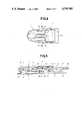
- a diving fin (or flipper) 1is made of relatively soft synthetic resin or rubber and provided with a heel strap 3 to fasten the heel after a diver has inserted the front of the foot into a foot pocket 2.
- the strap 3is coupled to said fin 1 by a buckle 6 consisting of a pair of first coupling members 4 respectively mounted on opposite sides of the foot pocket 2 and a pair of second coupling members 5 carried by opposite ends of said strap.
- the pin 19is partially surrounded by said strap 3 carrying on one side thereof a group of first latch teeth 21 spaced from one another longitudinally of said strap 3 and each having a cross-section shaped in an in equilateral triangle so that said first latch teeth confront the inner surface of the outer wall of the retaining frame 15
- the strap 3is provided adjacent each end thereof on the same side as the first latch teeth 21 with a stopper 22 serving to prevent the strap 3 from slipping off from the retaining frame 15 when said stopper 22 advances into said retaining frame 15 and thereby to prevent the front of the diver's foot from slipping off from the associated fin 1 due to said strap being excessively loosened
- the strap 3is further provided on both sides thereof adjacent each end with ridges 30 functioing as antiskid means for the driver's fingers when the driver handles the strap 3.
- the strap 3is coupled to the fin 1 by the respective buckles 6 at the opposite ends. According to the present invention, however, it is also possible that at least one end of the strap 3 is coupled by said buckle 6 to the fin 1 while the other end is unreleasably coupled to the fin 1 by suitable means and thereby the desired effect is achieved.
- the first coupling member 4is coupled to the fin 1, as previously mentioned, by pressing the first coupling member 4 towards the fin 1 with the projection 12d being maintained i alignment With the notch 10 so as to insert the flange 9 into the first coupling member 4 through the guide aperture 12a, then rotating the first coupling member 4 with respect to the fin 1 by a predetermined angle so that said projection 12d is angularly displaced with respect to said notch 10, and finally pulling the first coupling member 4 rearwardly with respect to the fin 1 to urge the neck portion 8 against its own elasticity through the constricted passage 12b into tight engagement with the interlocking aperture 12c.
Landscapes
- Health & Medical Sciences (AREA)
- General Health & Medical Sciences (AREA)
- Physical Education & Sports Medicine (AREA)
- Buckles (AREA)
- Switch Cases, Indication, And Locking (AREA)
Abstract
Description
Claims (5)
Applications Claiming Priority (2)
| Application Number | Priority Date | Filing Date | Title |
|---|---|---|---|
| JP62007716AJPS63174674A (en) | 1987-01-14 | 1987-01-14 | Diving fin |
| JP62-7716 | 1987-01-14 |
Publications (1)
| Publication Number | Publication Date |
|---|---|
| US4795385Atrue US4795385A (en) | 1989-01-03 |
Family
ID=11673460
Family Applications (1)
| Application Number | Title | Priority Date | Filing Date |
|---|---|---|---|
| US07/143,754Expired - LifetimeUS4795385A (en) | 1987-01-14 | 1988-01-14 | Diving fin |
Country Status (2)
| Country | Link |
|---|---|
| US (1) | US4795385A (en) |
| JP (1) | JPS63174674A (en) |
Cited By (36)
| Publication number | Priority date | Publication date | Assignee | Title |
|---|---|---|---|---|
| US5083954A (en)* | 1990-01-19 | 1992-01-28 | Jacobs Edward R | Swim fin retainer |
| EP0687484A1 (en)* | 1994-06-16 | 1995-12-20 | HTM SPORT S.p.A. | Swimming fin with buckle for fastening the heel strap |
| EP0721787A1 (en)* | 1995-01-11 | 1996-07-17 | HTM SPORT S.p.A. | Means for fastening the heel strap to a swim fin |
| US5657493A (en)* | 1994-03-25 | 1997-08-19 | Dacor Corporation | Diving mask with quick-release strap attachment |
| EP0792666A3 (en)* | 1996-02-23 | 1997-09-10 | TECHNISUB S.p.A. | Adjustable back strap for diving and swimming equipment |
| EP0884072A1 (en)* | 1997-06-13 | 1998-12-16 | Salvas Sub spa | Buckle particularly for the heel strap of open heel swim fins |
| US5868592A (en)* | 1997-05-13 | 1999-02-09 | Zeagle Systems, Inc. | Swim fin |
| US6179675B1 (en)* | 1998-09-10 | 2001-01-30 | Cressi-Sub S.P.A. | Swimming fin and manufacture process thereof |
| US6227924B1 (en) | 2000-03-06 | 2001-05-08 | Philip W. Miller | Swim fin heel strap |
| US6247983B1 (en)* | 2000-04-04 | 2001-06-19 | Tzong In Yeh | Adjusting strap structure for swim fins |
| WO2001052941A1 (en)* | 2000-01-17 | 2001-07-26 | Tabata Co., Ltd. | Buckle with strap for diving fin |
| US6341383B1 (en) | 1996-02-23 | 2002-01-29 | Technisub S.P.A. | Adjustable back strap for diving and swimming equipment |
| US6463640B1 (en)* | 2000-01-13 | 2002-10-15 | Douglas J. Toth | Strap connecting buckle |
| US6477717B1 (en)* | 2000-10-10 | 2002-11-12 | Q.D.S. Injection Molding, Inc. | Swim mask having virtual buckle pivot point |
| US20040127117A1 (en)* | 2002-07-19 | 2004-07-01 | Mccarthy Peter T. | High deflection hydrofoils and swim fins |
| US20050003719A1 (en)* | 1998-05-14 | 2005-01-06 | Mccarthy Peter T. | Methods for creating large scale focused blade deflections |
| US6884136B1 (en) | 2004-01-20 | 2005-04-26 | Mccarthy Peter T. | Dual adjustable strap designs for swim fins |
| US6923697B1 (en) | 2002-06-18 | 2005-08-02 | John L. Wagner | Universal open-heel dive fin replacement heel strap |
| US20050181689A1 (en)* | 1998-05-14 | 2005-08-18 | Mccarthy Peter T. | Methods for creating consistent large scale blade deflections |
| US20060107497A1 (en)* | 2004-11-23 | 2006-05-25 | Chin-Hsien Wung | Fastener with tie belt adjustment function |
| US20070173143A1 (en)* | 1996-01-11 | 2007-07-26 | Mccarthy Peter T | High efficiency hydrofoil and swim fin designs |
| US20100200078A1 (en)* | 2002-01-18 | 2010-08-12 | Swagelok Company | Method of assembling a ball valve |
| US20110065343A1 (en)* | 2009-09-11 | 2011-03-17 | Hsu Chien-Cheng | Detachable swim fin |
| US20110219590A1 (en)* | 2010-03-15 | 2011-09-15 | Joseph Anscher | Quick release buckle assembly |
| US8667651B2 (en)* | 2012-02-10 | 2014-03-11 | Ching-Wen Wang | Combined diving utensil |
| USD717694S1 (en) | 2013-09-05 | 2014-11-18 | National Molding, Llc | Release mechanism for a buckle assembly |
| US9364717B2 (en) | 2014-01-16 | 2016-06-14 | Kathleen Davis | Swimming fin |
| WO2016116785A1 (en) | 2015-01-23 | 2016-07-28 | Mares Spa | A swim or a scuba diving fin |
| US10029148B2 (en)* | 2016-12-15 | 2018-07-24 | Shin-Shi Shieh | Heel protective adjustable shoelace |
| CN108502128A (en)* | 2017-06-21 | 2018-09-07 | 广州琪高投资有限公司 | Detachable frog shoes |
| USD886223S1 (en) | 2019-02-08 | 2020-06-02 | Tyr Sport, Inc. | Swim fin |
| US10744374B1 (en) | 2019-04-08 | 2020-08-18 | Tyr Sport, Inc. | Swim fin with an upper portion having debossed regions and triple-bladed rails |
| US10905175B1 (en) | 2020-05-21 | 2021-02-02 | Tyr Sport, Inc. | Swimsuit with tension bands and reinforcement liners |
| US20220184459A1 (en)* | 2020-12-15 | 2022-06-16 | Cressi-Sub S.P.A. | Swimming and scuba diving fin with an adjustable elastic heel strap |
| USD985704S1 (en)* | 2021-08-10 | 2023-05-09 | Dongguan City Ren Tong Swimming & Diving Products Co., Ltd. | Swim fin |
| USD1073838S1 (en)* | 2021-08-18 | 2025-05-06 | Arturo Jesus FARIAS SERRA | Pair of swim fins |
Citations (6)
| Publication number | Priority date | Publication date | Assignee | Title |
|---|---|---|---|---|
| US2737668A (en)* | 1953-08-31 | 1956-03-13 | Cressi Giovanni | Fins for swimmers |
| US2779077A (en)* | 1952-02-23 | 1957-01-29 | Richard M Kline | Foot attachment for facilitating swimming |
| US3112503A (en)* | 1962-08-01 | 1963-12-03 | Barney B Girden | Swimming device |
| US3183529A (en)* | 1964-03-16 | 1965-05-18 | Beuchat Georges | Swimmer's foot-fin with thrust-accelerating device |
| US3940815A (en)* | 1973-05-03 | 1976-03-02 | Imperial Manufacturing Company | Quick foot release for swim fin |
| US4251894A (en)* | 1977-01-19 | 1981-02-24 | Farallon Industries, Inc. | Self-adjusting swim fin strap |
- 1987
- 1987-01-14JPJP62007716Apatent/JPS63174674A/enactiveGranted
- 1988
- 1988-01-14USUS07/143,754patent/US4795385A/ennot_activeExpired - Lifetime
Patent Citations (6)
| Publication number | Priority date | Publication date | Assignee | Title |
|---|---|---|---|---|
| US2779077A (en)* | 1952-02-23 | 1957-01-29 | Richard M Kline | Foot attachment for facilitating swimming |
| US2737668A (en)* | 1953-08-31 | 1956-03-13 | Cressi Giovanni | Fins for swimmers |
| US3112503A (en)* | 1962-08-01 | 1963-12-03 | Barney B Girden | Swimming device |
| US3183529A (en)* | 1964-03-16 | 1965-05-18 | Beuchat Georges | Swimmer's foot-fin with thrust-accelerating device |
| US3940815A (en)* | 1973-05-03 | 1976-03-02 | Imperial Manufacturing Company | Quick foot release for swim fin |
| US4251894A (en)* | 1977-01-19 | 1981-02-24 | Farallon Industries, Inc. | Self-adjusting swim fin strap |
Cited By (58)
| Publication number | Priority date | Publication date | Assignee | Title |
|---|---|---|---|---|
| US5083954A (en)* | 1990-01-19 | 1992-01-28 | Jacobs Edward R | Swim fin retainer |
| US5657493A (en)* | 1994-03-25 | 1997-08-19 | Dacor Corporation | Diving mask with quick-release strap attachment |
| EP0687484A1 (en)* | 1994-06-16 | 1995-12-20 | HTM SPORT S.p.A. | Swimming fin with buckle for fastening the heel strap |
| US5545067A (en)* | 1994-06-16 | 1996-08-13 | Htm Sport S.P.A | Swimming fin with buckle for fastening the heel strap |
| EP0721787A1 (en)* | 1995-01-11 | 1996-07-17 | HTM SPORT S.p.A. | Means for fastening the heel strap to a swim fin |
| US5607334A (en)* | 1995-01-11 | 1997-03-04 | Htm Sport S.P.A. | Swim fin equiped with buckle for the fastening of the heel strap |
| US20070173143A1 (en)* | 1996-01-11 | 2007-07-26 | Mccarthy Peter T | High efficiency hydrofoil and swim fin designs |
| US6341383B1 (en) | 1996-02-23 | 2002-01-29 | Technisub S.P.A. | Adjustable back strap for diving and swimming equipment |
| EP0792666A3 (en)* | 1996-02-23 | 1997-09-10 | TECHNISUB S.p.A. | Adjustable back strap for diving and swimming equipment |
| US5868592A (en)* | 1997-05-13 | 1999-02-09 | Zeagle Systems, Inc. | Swim fin |
| EP0884072A1 (en)* | 1997-06-13 | 1998-12-16 | Salvas Sub spa | Buckle particularly for the heel strap of open heel swim fins |
| US6185794B1 (en) | 1997-06-13 | 2001-02-13 | Salvas Sub S.P.A. | Buckle, particularly for the heel strap of open heel swim fins |
| US7465205B2 (en) | 1998-05-14 | 2008-12-16 | Mccarthy Peter T | Methods for creating consistent large scale blade deflections |
| US7581997B2 (en) | 1998-05-14 | 2009-09-01 | Mccarthy Peter T | Method for creating consistent large scale blade deflections |
| US7018256B2 (en) | 1998-05-14 | 2006-03-28 | Mccarthy Peter T | Methods for creating large scale focused blade deflections |
| US20080045095A1 (en)* | 1998-05-14 | 2008-02-21 | Mccarthy Peter T | Methods for creating consistent large scale blade deflections |
| US20050181689A1 (en)* | 1998-05-14 | 2005-08-18 | Mccarthy Peter T. | Methods for creating consistent large scale blade deflections |
| US20070173142A1 (en)* | 1998-05-14 | 2007-07-26 | Mccarthy Peter T | Methods for creating consistent large scale blade deflections |
| US7862395B2 (en) | 1998-05-14 | 2011-01-04 | Mccarthy Peter T | Methods for creating consistent large scale blade deflections |
| US20050003719A1 (en)* | 1998-05-14 | 2005-01-06 | Mccarthy Peter T. | Methods for creating large scale focused blade deflections |
| US20080032574A1 (en)* | 1998-05-14 | 2008-02-07 | Amy L. Goldman | Method for creating consistent large scale blade deflections |
| US6179675B1 (en)* | 1998-09-10 | 2001-01-30 | Cressi-Sub S.P.A. | Swimming fin and manufacture process thereof |
| US6463640B1 (en)* | 2000-01-13 | 2002-10-15 | Douglas J. Toth | Strap connecting buckle |
| WO2001052941A1 (en)* | 2000-01-17 | 2001-07-26 | Tabata Co., Ltd. | Buckle with strap for diving fin |
| US6398604B1 (en) | 2000-01-17 | 2002-06-04 | Tabata Co., Ltd. | Combination of strap and buckle for diving fins |
| US6227924B1 (en) | 2000-03-06 | 2001-05-08 | Philip W. Miller | Swim fin heel strap |
| US6247983B1 (en)* | 2000-04-04 | 2001-06-19 | Tzong In Yeh | Adjusting strap structure for swim fins |
| US6477717B1 (en)* | 2000-10-10 | 2002-11-12 | Q.D.S. Injection Molding, Inc. | Swim mask having virtual buckle pivot point |
| US20100200078A1 (en)* | 2002-01-18 | 2010-08-12 | Swagelok Company | Method of assembling a ball valve |
| US6923697B1 (en) | 2002-06-18 | 2005-08-02 | John L. Wagner | Universal open-heel dive fin replacement heel strap |
| US20070049140A1 (en)* | 2002-07-19 | 2007-03-01 | Mccarthy Peter T | High deflection hydrofoils and swim fins |
| US20070037459A1 (en)* | 2002-07-19 | 2007-02-15 | Mccarthy Peter T | High deflection hydrofoils and swim fins |
| US20050176318A1 (en)* | 2002-07-19 | 2005-08-11 | Mccarthy Peter T. | High deflection hydrofoils and swim fins |
| US7601041B2 (en) | 2002-07-19 | 2009-10-13 | Mccarthy Peter T | High deflection hydrofoils and swim fins |
| US6884134B2 (en) | 2002-07-19 | 2005-04-26 | Mccarthy Peter T. | High deflection hydrofoils and swim fins |
| US20040127117A1 (en)* | 2002-07-19 | 2004-07-01 | Mccarthy Peter T. | High deflection hydrofoils and swim fins |
| US20050186866A1 (en)* | 2004-01-20 | 2005-08-25 | Mccarthy Peter T. | Dual adjustable strap designs for swim fins |
| US6884136B1 (en) | 2004-01-20 | 2005-04-26 | Mccarthy Peter T. | Dual adjustable strap designs for swim fins |
| US20060107497A1 (en)* | 2004-11-23 | 2006-05-25 | Chin-Hsien Wung | Fastener with tie belt adjustment function |
| US20110065343A1 (en)* | 2009-09-11 | 2011-03-17 | Hsu Chien-Cheng | Detachable swim fin |
| US8087959B2 (en)* | 2009-09-11 | 2012-01-03 | Hsu Chien-Cheng | Detachable swim fin |
| US20110219590A1 (en)* | 2010-03-15 | 2011-09-15 | Joseph Anscher | Quick release buckle assembly |
| US8191213B2 (en)* | 2010-03-15 | 2012-06-05 | National Molding Llc | Quick release buckle assembly |
| US8667651B2 (en)* | 2012-02-10 | 2014-03-11 | Ching-Wen Wang | Combined diving utensil |
| USD717694S1 (en) | 2013-09-05 | 2014-11-18 | National Molding, Llc | Release mechanism for a buckle assembly |
| US9364717B2 (en) | 2014-01-16 | 2016-06-14 | Kathleen Davis | Swimming fin |
| WO2016116785A1 (en) | 2015-01-23 | 2016-07-28 | Mares Spa | A swim or a scuba diving fin |
| US10086235B2 (en)* | 2015-01-23 | 2018-10-02 | Mares S.P.A. | Swim or a scuba diving fin |
| US10029148B2 (en)* | 2016-12-15 | 2018-07-24 | Shin-Shi Shieh | Heel protective adjustable shoelace |
| CN108502128A (en)* | 2017-06-21 | 2018-09-07 | 广州琪高投资有限公司 | Detachable frog shoes |
| USD886223S1 (en) | 2019-02-08 | 2020-06-02 | Tyr Sport, Inc. | Swim fin |
| US10744374B1 (en) | 2019-04-08 | 2020-08-18 | Tyr Sport, Inc. | Swim fin with an upper portion having debossed regions and triple-bladed rails |
| US10905175B1 (en) | 2020-05-21 | 2021-02-02 | Tyr Sport, Inc. | Swimsuit with tension bands and reinforcement liners |
| US11058157B1 (en) | 2020-05-21 | 2021-07-13 | Tyr Sport, Inc. | Swimsuit with tension bands and reinforcement liners |
| US20220184459A1 (en)* | 2020-12-15 | 2022-06-16 | Cressi-Sub S.P.A. | Swimming and scuba diving fin with an adjustable elastic heel strap |
| US12145026B2 (en)* | 2020-12-15 | 2024-11-19 | Cressi-Sub S.P.A. | Swimming and scuba diving fin with an adjustable elastic heel strap |
| USD985704S1 (en)* | 2021-08-10 | 2023-05-09 | Dongguan City Ren Tong Swimming & Diving Products Co., Ltd. | Swim fin |
| USD1073838S1 (en)* | 2021-08-18 | 2025-05-06 | Arturo Jesus FARIAS SERRA | Pair of swim fins |
Also Published As
| Publication number | Publication date |
|---|---|
| JPS63174674A (en) | 1988-07-19 |
| JPH0138510B2 (en) | 1989-08-15 |
Similar Documents
| Publication | Publication Date | Title |
|---|---|---|
| US4795385A (en) | Diving fin | |
| US5320097A (en) | Endotracheal tube holding and securing device | |
| US4321734A (en) | Clasp assembly | |
| US3789467A (en) | Helmet chin strap | |
| US4608735A (en) | Sliding bar buckle | |
| US4999846A (en) | Strap and buckle assembly | |
| US4903378A (en) | Strap adjustment assembly | |
| US5379496A (en) | Cord release buckle | |
| CA2759930C (en) | Locking device for a buckle | |
| US3686715A (en) | Strap system for material handling | |
| US3605207A (en) | Safety belt buckle | |
| US4501027A (en) | Quick release weight belt and buckle therefor | |
| US4110847A (en) | Quick fastening and adjusting safety clasp especially for safety helmets | |
| US7836561B2 (en) | Buckle for diving goggles or the like | |
| CA2103544A1 (en) | Lock for safety belt, particularly for children | |
| KR900008811Y1 (en) | Pull tab attachment for slide fastener slider | |
| US6327751B1 (en) | Code holding buckle | |
| US6185794B1 (en) | Buckle, particularly for the heel strap of open heel swim fins | |
| JP2001198236A (en) | Buckle with strap | |
| GB2150632A (en) | Buckles | |
| US20130092139A1 (en) | Quick release buckle | |
| US5083954A (en) | Swim fin retainer | |
| US5531622A (en) | Quick disconnect leash for surfboard and the like | |
| US4502192A (en) | Separable fastener | |
| US3979800A (en) | Buckle |
Legal Events
| Date | Code | Title | Description |
|---|---|---|---|
| STCF | Information on status: patent grant | Free format text:PATENTED CASE | |
| AS | Assignment | Owner name:TABATA CO. LTD., 1-3-17, HIGASHI-KOMAGATA, SUMIDA- Free format text:ASSIGNMENT OF ASSIGNORS INTEREST.;ASSIGNOR:MATSUOKA, MITSUSHIRO;REEL/FRAME:004997/0620 Effective date:19880804 | |
| FEPP | Fee payment procedure | Free format text:PAYOR NUMBER ASSIGNED (ORIGINAL EVENT CODE: ASPN); ENTITY STATUS OF PATENT OWNER: SMALL ENTITY | |
| FPAY | Fee payment | Year of fee payment:4 | |
| FEPP | Fee payment procedure | Free format text:PAYER NUMBER DE-ASSIGNED (ORIGINAL EVENT CODE: RMPN); ENTITY STATUS OF PATENT OWNER: SMALL ENTITY Free format text:PAYOR NUMBER ASSIGNED (ORIGINAL EVENT CODE: ASPN); ENTITY STATUS OF PATENT OWNER: SMALL ENTITY | |
| FPAY | Fee payment | Year of fee payment:8 | |
| FEPP | Fee payment procedure | Free format text:PAT HOLDER CLAIMS SMALL ENTITY STATUS - SMALL BUSINESS (ORIGINAL EVENT CODE: SM02); ENTITY STATUS OF PATENT OWNER: SMALL ENTITY | |
| FPAY | Fee payment | Year of fee payment:12 |