US4794649A - Radio communication system with power saving disablement prior to call handling processes - Google Patents
Radio communication system with power saving disablement prior to call handling processesDownload PDFInfo
- Publication number
- US4794649A US4794649AUS07/043,866US4386687AUS4794649AUS 4794649 AUS4794649 AUS 4794649AUS 4386687 AUS4386687 AUS 4386687AUS 4794649 AUS4794649 AUS 4794649A
- Authority
- US
- United States
- Prior art keywords
- power saving
- signal
- station
- disabling
- relayed
- Prior art date
- Legal status (The legal status is an assumption and is not a legal conclusion. Google has not performed a legal analysis and makes no representation as to the accuracy of the status listed.)
- Expired - Lifetime
Links
- 238000004891communicationMethods0.000titleclaimsabstractdescription20
- 238000000034methodMethods0.000titleclaimsdescription6
- 230000008569processEffects0.000titledescription2
- 230000004044responseEffects0.000claimsabstractdescription16
- 230000005540biological transmissionEffects0.000claimsdescription13
- 238000001514detection methodMethods0.000claimsdescription10
- 230000007704transitionEffects0.000claimsdescription7
- 230000000737periodic effectEffects0.000claimsdescription5
- 238000011084recoveryMethods0.000description11
- 238000010586diagramMethods0.000description6
- 238000011144upstream manufacturingMethods0.000description4
- 230000009471actionEffects0.000description3
- 230000008859changeEffects0.000description2
- 230000001143conditioned effectEffects0.000description2
- 230000008054signal transmissionEffects0.000description2
- 230000011664signalingEffects0.000description2
- 230000001360synchronised effectEffects0.000description2
- 239000012141concentrateSubstances0.000description1
- 238000005259measurementMethods0.000description1
- 238000012986modificationMethods0.000description1
- 230000004048modificationEffects0.000description1
- 231100000989no adverse effectToxicity0.000description1
- 238000012545processingMethods0.000description1
- 230000001960triggered effectEffects0.000description1
Images


Classifications
- H—ELECTRICITY
- H04—ELECTRIC COMMUNICATION TECHNIQUE
- H04B—TRANSMISSION
- H04B7/00—Radio transmission systems, i.e. using radiation field
- H04B7/14—Relay systems
- H—ELECTRICITY
- H04—ELECTRIC COMMUNICATION TECHNIQUE
- H04B—TRANSMISSION
- H04B7/00—Radio transmission systems, i.e. using radiation field
- H04B7/14—Relay systems
- H04B7/15—Active relay systems
- H04B7/155—Ground-based stations
- H—ELECTRICITY
- H04—ELECTRIC COMMUNICATION TECHNIQUE
- H04B—TRANSMISSION
- H04B7/00—Radio transmission systems, i.e. using radiation field
- H—ELECTRICITY
- H04—ELECTRIC COMMUNICATION TECHNIQUE
- H04B—TRANSMISSION
- H04B7/00—Radio transmission systems, i.e. using radiation field
- H04B7/24—Radio transmission systems, i.e. using radiation field for communication between two or more posts
- H04B7/26—Radio transmission systems, i.e. using radiation field for communication between two or more posts at least one of which is mobile
- H—ELECTRICITY
- H04—ELECTRIC COMMUNICATION TECHNIQUE
- H04W—WIRELESS COMMUNICATION NETWORKS
- H04W52/00—Power management, e.g. Transmission Power Control [TPC] or power classes
- H04W52/02—Power saving arrangements
- H04W52/0209—Power saving arrangements in terminal devices
- H04W52/0225—Power saving arrangements in terminal devices using monitoring of external events, e.g. the presence of a signal
- H04W52/0229—Power saving arrangements in terminal devices using monitoring of external events, e.g. the presence of a signal where the received signal is a wanted signal
- H—ELECTRICITY
- H04—ELECTRIC COMMUNICATION TECHNIQUE
- H04W—WIRELESS COMMUNICATION NETWORKS
- H04W52/00—Power management, e.g. Transmission Power Control [TPC] or power classes
- H04W52/02—Power saving arrangements
- H04W52/0209—Power saving arrangements in terminal devices
- H04W52/0225—Power saving arrangements in terminal devices using monitoring of external events, e.g. the presence of a signal
- H04W52/0238—Power saving arrangements in terminal devices using monitoring of external events, e.g. the presence of a signal where the received signal is an unwanted signal, e.g. interference or idle signal
- H—ELECTRICITY
- H04—ELECTRIC COMMUNICATION TECHNIQUE
- H04W—WIRELESS COMMUNICATION NETWORKS
- H04W76/00—Connection management
- H04W76/10—Connection setup
- H—ELECTRICITY
- H04—ELECTRIC COMMUNICATION TECHNIQUE
- H04W—WIRELESS COMMUNICATION NETWORKS
- H04W88/00—Devices specially adapted for wireless communication networks, e.g. terminals, base stations or access point devices
- H04W88/02—Terminal devices
- H04W88/04—Terminal devices adapted for relaying to or from another terminal or user
- Y—GENERAL TAGGING OF NEW TECHNOLOGICAL DEVELOPMENTS; GENERAL TAGGING OF CROSS-SECTIONAL TECHNOLOGIES SPANNING OVER SEVERAL SECTIONS OF THE IPC; TECHNICAL SUBJECTS COVERED BY FORMER USPC CROSS-REFERENCE ART COLLECTIONS [XRACs] AND DIGESTS
- Y02—TECHNOLOGIES OR APPLICATIONS FOR MITIGATION OR ADAPTATION AGAINST CLIMATE CHANGE
- Y02D—CLIMATE CHANGE MITIGATION TECHNOLOGIES IN INFORMATION AND COMMUNICATION TECHNOLOGIES [ICT], I.E. INFORMATION AND COMMUNICATION TECHNOLOGIES AIMING AT THE REDUCTION OF THEIR OWN ENERGY USE
- Y02D30/00—Reducing energy consumption in communication networks
- Y02D30/70—Reducing energy consumption in communication networks in wireless communication networks
Definitions
- the present inventionrelates to power saving for radio communication systems.
- origination of a callrequires transmission of a long packet of data from terminal stations during an active interval of the system to request the base station to issue a series of signals according to protocols.
- the transmission of a call origination request signalresults in the disablement of power saving in the repeater and terminal stations to permit them to process the signals.
- call origination attempts from terminal stationstend to concentrate during the limited time interval and encouter data collision.
- the base stationwould generate a series of protocols, resulting in fruitless data exchanges along the network causing a systemwide traffic congestion.
- the above objectis obtained by transmitting a disabling signal during the limited active period from a terminal station to a repeater station prior to the transmission of a call request signal.
- the disabling signaldisables the power saving operations of the repeater station and the own terminal station and allows the latter to receive signals relayed through the active repeater station and send a call request signal to it so that a series of call processing signals can be handled during the power saving disabled period. Since the power saving disabling signal can be a short packet of data and induces no protocol actions in the base station, its probability of encountering collision is very slight and hence a systemwide traffic congestion cannot occur even if data collision occurs.
- the power saving disabling signalis transmitted after a randomly determined period of time following a transition from an inactive period to an active period.
- the terminal stationis arranged to transmit a call request signal after a randomly determined period following the reception of a signal relayed by the repeater station which is rendered active in response to the disabling signal.
- a radio communication system of the inventioncomprises a base station for transmitting a power saving signal and an information signal, a repeater station for relaying the signals, and a plurality of terminal stations for communicating with the base station through the repeater station.
- the repeater stationincludes power saving circuitry responsive to the power saving signal to cut off power supplies to its major power consumptive components during a preset interval which alternates with an active interval during which power is supplied to the components.
- Each terminal stationincludes power saving circuitry responsive to the power saving signal relayed by the repeater station to cut off power supplies to its major power consumptive components during the preset interval and power saving disabling circuitry for transmitting a power saving disabling signal to the repeater station during the active interval in response to a request for call and disabling its power saving circuitry for the duration of the preset interval.
- the repeater stationincludes power saving disabling circuitry which is responsive to the power saving disabling signal from a terminal station to disable its power saving circuitry for the duration of the preset interval to thereby permit the information signal to be relayed to the terminal station which has transmitted the power saving disabling signal.
- Each terminal stationtransmits a call request signal to the repeater station to thereby permit it to be handled during the interval in which power saving is disabled.
- FIG. 1is an illustration of a digital radio concentrator system
- FIG. 2is a block diagram of a base station
- FIG. 3is an illustration of the format of data transmitted constantly from the base station
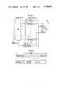
- FIG. 4is a block diagram of a repeater station
- FIG. 5is a circuit diagram of a battery saving code detector
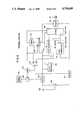
- FIG 6is a block diagram of a terminal station
- FIGS. 7a and 7bare illustrations of the formats of data transmitted from the terminal station according to the invention.
- FIG. 8is a time diagram useful for a full understanding of the present invention.
- a time division multiple access (TDMA) radio concentrator system of the inventioncomprises a base station 10 connected to subscriber line terminals of an end office switching system 11 of the public telecommunication network, repeater stations 12 and 13 and terminal stations 14 and 15 which are located in remote, thinnly populated areas.
- Terminal stations 14are located in an area that is appropriate for establishing communications with the repeater station 12 and terminal stations 15 are located in another area approprite for communications with the repeater station 13. All the terminal stations 14 and 15 have their corresponding subscriber line terminals at the end office switching system 11.
- the base station 10provides line concentration by switching the subscriber lines to a smaller number of "downstream" TDMA channels and as viewed from the terminal stations it provides deconcentration by switching the "upstream" TDMA channels to the subscriber lines.
- Each terminal stationhas connected to it a subscriber station such as telephone and telefax machine. All the repeater and terminal stations operate on individual battery supplies.
- the base stationcomprises a line concentrator 20, a plurality of PCM codecs (coder/decoders) 21 provided in number corresponding to the number of two-way TDMA channels and a time slot controller 22.
- Time slot controller 22is associated with each of the codecs 21, concentrator 20, radio transmitter 23 and radio receiver 24.
- Each codec 21has a hybrid, a PCM coder for encoding an outgoing analog signal coupled through the hybrid from the concentrator 20 and applying the encoded outgoing signal on a specified outgoing time slot to transmitter 23 and a PCM decoder for decoding an incoming digital signal from receiver 24 on a specified incoming time slot and applying the decoded signal through the hybrid to the concentrator 20.
- Transmitter 23modulates a carrier with the TDM bit stream using a digital modulation technique and amplifies the modulated carrier to a level sufficient for transmission, the output of transmitter 23 being coupled through duplexer 25 to antenna 26.
- Receiver 24amplifies and demodulates a digitally modulated RF signal received by antenna 26 to recover baseband TDM signals.
- time-slot controller 22generates a timing reference to permit each codec to determine a particular one of the time slots TS0 to TSn of a "frame".
- Time slot TS0comprises a plurality of "fields".
- the first fieldcontains a preamble from which the receiving stations recover clock signals.
- the preambleconsists of a series of 16 bits of alternating binary 1's and 0's.
- a frame sync codewhich is also a 16-bit series of a unique code format (typically, "1010010100110110", is inserted to the second field of the time slot TS0.
- a battery saving (BS) codeis inserted to the third field of the first time slot and is followed by a control field in which signaling and time slot assignment information is inserted.
- the BS codedetermines the timing reference with which all the repeater and terminal stations are synchronized to cut off their battery supplies at periodic intervals to conserve their power.
- the BS codecomprises "1010" (BS-ON) for power cut-off and "0101" (BS-OFF) for power restoration. To achieve most efficient power savings, frames containing the BS-ON code are repeated so as to continue for a period of time much longer than the period in which frames having the BS-OFF code continue.
- the time slot TS0is followed by a series of information carrying time slots TS1 to TSn each having a 16-bit time-slot sync having a bit pattern "101001010011011" which differs from the frame sync in that the least significant bit is a binary 1.
- the time slots TS1 to TSncorrespond respectively to the codecs 21.
- a consecutive series of power-cutoff D-framesalternates with a consecutive series of power-restoration C-frames and transmitted from the antenna 26 on a broadcast mode through repeater stations 12 and 13 to all terminal stations 14 and 15.
- FIG. 4illustrates details of each repeater station.
- the broadcast time-division multiplexed signalis intercepted by an antenna 30 and applied through duplexer 31 to a radio receiver 32 and applied on a "downstream" signal transmission path including a delay 33 and a gate 34 to a radio transmitter 35 whose output is coupled through duplexer 36 to antenna 37.
- Burst signals transmitted on assigned time slots from the associated terminal stationare received by antenna 37, passed through duplexer 36 to a radio receiver and applied on an "upstream" signal transmission path including a delay 39 and a gate 40 to a radio transmitter 41 and thence to duplexer 31.
- Receivers 32, 38 and transmitters 35 and 41which are the main power consumptive components of the repeater station, are powered from a power source, or storage batteries 42 through normally open contacts of a power-saving switch 43 which is controlled in a manner as will be described.
- Receiver 32amplifies the downstream radio-frequency TDM signal and demodulates it to recover the baseband TDM signal.
- the output of receiver 32is applied to a clock recovery circuit 44, a sync detector 45 and a BS detector 46.
- Clock recovery circuit 44detects a preamble from the received bit stream to recover clock timing and supplies clock pulses to sync detector 45 and BS detector 46.
- Sync detector 45essentially comprises a shift register which is clocked by the clock recovery circuit 44 to accept the output of receiver 32 and a digital comparator which compares the binary states of the loaded data bit stream with the code format of the sync and generates an equality output when they match, this output being applied as a trigger signal to a monostable multivibrator 47 and as an enabling signal to the BS detector 46.
- the downstream TDM output of receiver 32is timed by delay 33 so that it passes to the transmitter 35 through gate 34 in response to a gate-on pulse from the monostable 47.
- Transmitter 35modulates the output of gate 34 upon a carrier frequency different from the carrier frequency transmitted from the base station and applies it through duplexer 36 to antenna 37.
- the BS detector 46is constructed in a manner similar to sync detector to detect the BS-ON code immediately following the detection of a sync code by sync detector 45.
- a timer 48is connected to the output of BS detector 46 to operate the battery-saving switch 43 through an OR gate 49.
- Timer 48may be formed of a monostable multivibrator and an inverter connected to the output of the monostable to generate a logical 0 output (power cutoff signal) of a duration slightly longer than the duration of a series of D-frames in response to the receipt of a single BS-ON code that occurs at the first of the series of D-frames.
- BS detector 46is implemented by a shift register 54 which is clocked by the clock recovery circuit 44 to receive the output of receiver 32.
- a digital comparator 55compares the common bit pattern (i.e., the 15-bit pattern of "10100101001101") of the frame and time-slot sync codes with the contents of the binary positions Q0 to Q14 of the shift register 54 to supply a coincidence output upon the arrival of each frame and time-slot sync code to an AND gate 57 to which the clock pulses are also applied through an inverter 58.
- a second digital comparator 56makes comparison with the BS-ON code pattern "1010" with the contents of the binary positions Q16 to Q19 of the shift register to supply a coincidence output at the beginning of each frame to the D input of a D-flip-flop 59 having a clock input to which the output of AND gate 57 is applied.
- the output of timer 48is connected to the reset input of D-flip-flop 59 to prevent it from responding to BS-ON codes that occur after the timer 48 has been activated in response to the detection of a BS-ON code of first occurrence during the power saving disablement.
- D-flip-flop 59switches to a significant binary level at the trailing edge of a pulse from clock recovery circuit 44 when the flip-flop is supplied with logical 1 outputs from both comparators during the first time slot TS0 and switches to an insignificant binary level at the trailing edge of a subsequent clock pulse when the flip-flop is supplied with logical 1 and 0 outputs from comparators 55 and 56, respectively, during the second time slot TS1.
- D-flip-flop 59generates an output pulse with a duration of a single time slot at the starting point of each D-frame.
- the switch 43remains open to cut off power supplies to the power consumptive units.
- the output of timer 48automatically switches to a logical 1 level to cause the switch 43 to close its contacts to reactivate the power consumptive units.
- the receiver 38In the "upstream" section of the repeater station, the receiver 38 amplifies the radio-frequency TDM signal from antenna 37 and demodulates it to recover the baseband TDM signal which is applied to a clock recovery circuit 50.
- Clock recovery circuit 50detects a preamble from the bit stream received from the terminal stations and recovers clock timing.
- a sync detector 51is synchronized to the clock pulse from the clock recovery circuit 50 and detects a sync code contained in the received TDM bit stream.
- the output of sync detector 51drives a monostable multivibrator 52 to open the gate 40 to pass the TDM bit stream, which is appropriately timed by the delay 39, to transmitter 41 where it is modulated upon a particular carrier frequency and amplified for transmission to the base station.
- a battery saving inhibit flip-flop 53is provided. This flip-flop responds to the output of sync detector 51 by supplying a logical 1 output through 0R gate 49 to switch 43 to inhibit battery saving operation and further responds to the logical 1 output (power restoring signal) of timer 48 by supplying a logical 0 output to switch 43 to allow it to open its contacts to resume battery saving operation.
- each terminal stationcouples battery supplies to a receiver 60 and a transmitter 61 from a storage battery 62 through a power saving switch 63.
- the relayed radio-frequency TDM signalis intercepted by antenna 64 and applied through duplexer 65 to receiver 60 where it is amplified and demodulated.
- the output of receiver 60is applied to the decoder input of a PCM codec 66, the encoder output of which is connected to transmitter 61.
- Codec 66is connected over a subscriber line to a telephone set 67 to convert the analog speech signal into digital form and insert the digital signal to a time slot specified by a controller 68 for application to transmitter 61.
- Codec 66detects a digital signal on a specified time slot of the recovered TDM baseband signal and converts it to an analog form for application to the telephone 67.
- a clock recovery circuit 69derives clock timing from the preamble of the relayed bit stream and causes a sync detector 70 to detect a sync code immediately following the preamble.
- Sync detector 70enables a BS detector 71 to detect a BS-ON code from the battery saving field of the bit stream.
- the BS detector 71drives a timer 72 upon detection of a BS-ON code to cause a power cutoff signal of the same duration as in the repeater station to be ggenerated. This power cutoff signal is applied through an OR gate 73 to power saving switch 63.
- Controller 68is responsive to the outputs of clock recovery circuit 69 and sync detector 70 to detect the time slot on which the "downstream" signal is carried to cause the codec 66 to decode the digital signal on the detected time slot to analog form for application to telephone 67 and specify a time slot on which the "upstream" digital signal to be inserted.
- a code generator 74is connected to the controller 68 to generate a bit sequence comprising a preamble and a sync code to be inserted to the beginning of a specified time slot to permit the receiving stations to establish clock and frame synchronization whenever speech or signaling information is transmitted.
- controller 68monitors the output of timer 72 to detect a transition from an active interval (BS-OFF) to an inactive interval (BS-ON) and generates a battery saving inhibit command signal after a random time period following the detection of the transition which occurs after telephone 67 goes off hook for call origination.
- This BS inhibit command signalis applied to the code generator 74 to cause a BS inhibit code to be generated.
- This inhibit codecomprises a preamble, a sync code and a dummy code as shown in FIG. 7a to be transmitted to the repeater station to inhibit its battery saving operation.
- This BS inhibit command signalis also applied to the set input of a battery saving inhibit flip-flop 75 to cause it to apply a logical 1 output through OR gate 73 to switch 63 to close its contacts.
- Flip-flop 75is reset in response to a power cutoff signal from timer 72 to apply a logical 0 output to switch 63 to resume battery saving operation.
- controller 68is conditioned to monitor the arrival of a sync code contained in a received bit stream to recognize that the battery saving operation is inhibited in the associated repeater station. On recognizing this fact, the controller 68 proceeds to apply a call request command signal to the code generator 74 after a random time period following the detection of a "downstream" sync code to cause a call request code to be generated.
- This call request signalcomprises a preamble, a sync code and control codes as shown in FIG. 7b. The length of this signal is much longer than the BS inhibit signal of FIG. 7a.
- Base station 10constantly broadcasts a series of C-frames and a series of D-frames during alternate periods, so that power supplies are cut off in synchronism in all the repeater and terminal stations. More specifically, in each repeater station, sync detector 45 monitors the BS field of each frame. When the repeater station is in receipt of a series of C-frames, timer 48 causes a power supply signal to be applied to switch 43 to supply power to its power consumptive units. When it is receiving a series of D-frames, timer 48 switches its output state to cause a power cutoff signal to be applied to switch 43 to cut off power supplies to the power consumptive units.
- sync detector 71monitors the BS field of each frame relayed from the associated repeater station.
- timer 72causes a power supply signal to be applied to switch 63 to supply power to its power consumptive units.
- timer 72switches its output state to cause a power cutoff signal to be applied to switch 63 to cut off power supplies to the power consumptive units.
- Controller 68monitors the output of timer 72 and generates a BS inhibit command signal after a random time period T 1 following the occurrence of a power supply signal (logical 0) at the output of timer 72 at time t 1 , whereupon the system enters an active mode.
- the BS inhibit command signalis applied to the code generator 74 to cause a BS inhibit signal (FIG. 7a) to be applied to transmitter 61 and transmitted and received by the associated repeater station.
- the BS inhibit commandcauses a power-saving disablement signal (logical 1) to be supplied from flip-flop 75 through OR gate 73 to the switch 63 so that its contacts are kept closed during the period following the termination of the power supply signal from the timer 72.
- clock timingis recovered from the preamble of the received inhibit signal by the clock recovery circuit 50 and fed to the sync detector 51 to enable it to detect a sync code.
- Flip-flop 53is triggered into set condition in response to the sync code, applying a power-saving disablement signal (logical 1) through OR gate 49 to switch 43 to keep its contacts closed during the period following the termination of the power supply signal from the timer 48 in a manner similar to the terminal station.
- a power-saving disablement signal(logical 1) through OR gate 49 to switch 43 to keep its contacts closed during the period following the termination of the power supply signal from the timer 48 in a manner similar to the terminal station.
- the "downstream" TDMA signalchanges from C-frames to D-frames and timers 48 and 72 of the repeater and terminal stations change their outputs to logical 0. Therefore, the other repeater station and terminal stations enter an inactive mode at time t 2 .
- the controller 68 of the terminal stationAfter transmission of a BS inhibit signal, the controller 68 of the terminal station is conditioned to monitor the output of sync detector 70. If it detects a sync code from the "downstream" TDMA signal at time t 2 , the controller 68 recognizes that the repeater station is still active and initiates measurement of the length of time elapsed from time t 2 . When a randomly determined amount of time T 2 is reached, the controller 68 issues a call request command to the code generator 74 to cause a call request signal (FIG. 7b) to be transmitted and received by the repeater station and relayed to the base station 10 to permit it to handle the call request signal during the time period in which the repeater and terminal stations concerned would otherwise remain inactive.
- a call request signalFOG. 7b
- This power saving disablementexpires at time t 3 and the whole system again enters an active state to allow various stations to reinitiate call handling actions.
- the BS inhibit signalrequires no protocol operation. Thus, collisiosn of a BS inhibit signal does not result in a system failure. Since the call request signal is processed when power saving is disabled and this interval is much longer than the active interval, there is a freedom of choice for the determination of the time at which the call request signal can be transmitted. Since the call request signal has a long wordlength which implies a high likelihood of data collision and this type of signal induces protocol operations in the base station, data collision of the call request signal would result in transmissions of meaningless data bits causing a systemwide traffic congestion.
- the freedom of choice allowed for the transmission of the call request signalserves to avoid data collision and hence systewide congestion.
- the BS inhibit signal and call request signalare transmitted at randomly determined times T 1 and T 2 , there is a very slight chance of collision with signals transmitted from other stations. To further decrease the chance of data collision, it is preferred that such signals be transmitted in succession at random times.
Landscapes
- Engineering & Computer Science (AREA)
- Computer Networks & Wireless Communication (AREA)
- Signal Processing (AREA)
- Mobile Radio Communication Systems (AREA)
- Radio Relay Systems (AREA)
Abstract
Description
Claims (14)
Applications Claiming Priority (2)
| Application Number | Priority Date | Filing Date | Title |
|---|---|---|---|
| JP61-103592 | 1986-05-06 | ||
| JP61103592AJPH06105884B2 (en) | 1986-05-06 | 1986-05-06 | Wireless telephone system |
Publications (1)
| Publication Number | Publication Date |
|---|---|
| US4794649Atrue US4794649A (en) | 1988-12-27 |
Family
ID=14358037
Family Applications (1)
| Application Number | Title | Priority Date | Filing Date |
|---|---|---|---|
| US07/043,866Expired - LifetimeUS4794649A (en) | 1986-05-06 | 1987-04-29 | Radio communication system with power saving disablement prior to call handling processes |
Country Status (7)
| Country | Link |
|---|---|
| US (1) | US4794649A (en) |
| EP (1) | EP0245024B1 (en) |
| JP (1) | JPH06105884B2 (en) |
| KR (1) | KR910000304B1 (en) |
| AU (1) | AU585810B2 (en) |
| CA (1) | CA1257653A (en) |
| DE (1) | DE3782850T2 (en) |
Cited By (99)
| Publication number | Priority date | Publication date | Assignee | Title |
|---|---|---|---|---|
| US4918431A (en)* | 1988-10-31 | 1990-04-17 | Motorola, Inc. | Method and apparatus for automatically adjusting the output power of a transmitter |
| US4921464A (en)* | 1987-03-12 | 1990-05-01 | Kabushiki Kaisha Toshiba | Radio channel search system |
| US4977611A (en)* | 1987-02-20 | 1990-12-11 | Nec Corporation | Portable radio apparatus having battery saved channel scanning function |
| US5005198A (en)* | 1988-07-11 | 1991-04-02 | Sharp Kabushiki Kaisha | Cordless telephone apparatus |
| US5054052A (en)* | 1989-04-03 | 1991-10-01 | Mitsubishi Denki Kabushiki Kaisha | Mobile telephone device with low power consumption |
| US5077830A (en)* | 1988-02-17 | 1991-12-31 | Indesys, Inc. | Method and apparatus to selectively address recipients and recover missing messages on a broadcast distribution network |
| US5081667A (en)* | 1989-05-01 | 1992-01-14 | Clifford Electronics, Inc. | System for integrating a cellular telephone with a vehicle security system |
| WO1992009146A1 (en)* | 1990-10-31 | 1992-05-29 | Motorola, Inc. | Battery saver for a communication device |
| US5128938A (en)* | 1989-03-03 | 1992-07-07 | Motorola, Inc. | Energy saving protocol for a communication system |
| US5140589A (en)* | 1989-11-01 | 1992-08-18 | Nec Corporation | Battery saving system for interrupting power supplies at intervals variable with traffic pattern |
| US5140698A (en)* | 1989-03-31 | 1992-08-18 | Mitsubishi Denki Kabushiki Kaisha | Mobile telephone system with intermittent control of receiver components in standby state |
| US5150361A (en)* | 1989-01-23 | 1992-09-22 | Motorola, Inc. | Energy saving protocol for a TDM radio |
| US5241542A (en)* | 1991-08-23 | 1993-08-31 | International Business Machines Corporation | Battery efficient operation of scheduled access protocol |
| US5349694A (en)* | 1990-08-22 | 1994-09-20 | Mitsubishi Denki Kabushiki Kaisha | Radio relay system with a multiplex separation circuit and control for providing time delay multiplex operation of receiver and transmitter |
| WO1994022239A1 (en)* | 1993-03-24 | 1994-09-29 | Telefonaktiebolaget Lm Ericsson | Control of a radio communications system base station |
| US5359594A (en)* | 1992-05-15 | 1994-10-25 | International Business Machines Corporation | Power-saving full duplex nodal communications systems |
| US5442681A (en)* | 1991-09-24 | 1995-08-15 | Motorola Inc. | Method of exchanging communicated signals between a remote base site and a central site in a communication system |
| US5444444A (en)* | 1993-05-14 | 1995-08-22 | Worldwide Notification Systems, Inc. | Apparatus and method of notifying a recipient of an unscheduled delivery |
| WO1996003811A1 (en)* | 1994-07-21 | 1996-02-08 | Interdigital Technology Corporation | Power consumption control method and apparatus for a communication system subscriber unit |
| US5524211A (en)* | 1991-02-13 | 1996-06-04 | Hewlett Packard Company | System for employing select, pause, and identification registers to control communication among plural processors |
| US5584048A (en)* | 1990-08-17 | 1996-12-10 | Motorola, Inc. | Beacon based packet radio standby energy saver |
| US5590396A (en)* | 1994-04-20 | 1996-12-31 | Ericsson Inc. | Method and apparatus for a deep-sleep mode in a digital cellular communication system |
| US5655219A (en)* | 1993-03-05 | 1997-08-05 | Hitachi, Ltd. | Wireless LAN system capable of re-transmission under management of a base station device to a destination mobile terminal device |
| US5678192A (en)* | 1992-11-27 | 1997-10-14 | Nokia Telecommunications Oy | Radio system |
| US5714948A (en)* | 1993-05-14 | 1998-02-03 | Worldwide Notifications Systems, Inc. | Satellite based aircraft traffic control system |
| US5838257A (en)* | 1996-05-24 | 1998-11-17 | Trw Inc. | Keyless vehicle entry system employing portable transceiver having low power consumption |
| US5892817A (en)* | 1995-07-10 | 1999-04-06 | Will; Craig Alexander | Wireless system for alerting individual to incoming telephone call |
| US5974325A (en)* | 1991-09-24 | 1999-10-26 | Motorola, Inc. | Cellular radio system using common radio backbone |
| US5991635A (en)* | 1996-12-18 | 1999-11-23 | Ericsson, Inc. | Reduced power sleep modes for mobile telephones |
| WO2001003326A1 (en)* | 1996-12-20 | 2001-01-11 | Airnet Communications Corporation | Time slot recovery for remote in-band translator in time division multiple access wireless system |
| US6192230B1 (en)* | 1993-03-06 | 2001-02-20 | Lucent Technologies, Inc. | Wireless data communication system having power saving function |
| US6243399B1 (en) | 1994-07-21 | 2001-06-05 | Interdigital Technology Corporation | Ring signal generator |
| US20010008519A1 (en)* | 1987-11-20 | 2001-07-19 | Kaewell John David | Base station emulator |
| US20010031624A1 (en)* | 1999-12-29 | 2001-10-18 | Schmutz Thomas R. | Discrete power level coding for indicating uplink mobile receive level in a wireless repeater system |
| US6314366B1 (en) | 1993-05-14 | 2001-11-06 | Tom S. Farmakis | Satellite based collision avoidance system |
| US20010051530A1 (en)* | 2000-06-01 | 2001-12-13 | Fujitsu Limited | Communication monitoring and controlling for prevention of RF signal interference in information processing device having plural wireless communication units |
| US6339694B1 (en)* | 1998-03-30 | 2002-01-15 | Airnet Communications Corporation | Method and apparatus employing automatic RF muting and wireless remote control of RF downlink transmission for a wireless repeater |
| US20020016180A1 (en)* | 2000-07-25 | 2002-02-07 | Derosier J. David | Communication device intervention system and method |
| US6374311B1 (en)* | 1991-10-01 | 2002-04-16 | Intermec Ip Corp. | Communication network having a plurality of bridging nodes which transmit a beacon to terminal nodes in power saving state that it has messages awaiting delivery |
| US20020044595A1 (en)* | 2000-10-13 | 2002-04-18 | Ulrich Friedrich | Method for transmitting a plurality of information symbols |
| WO2002056485A1 (en)* | 2001-01-09 | 2002-07-18 | Koninklijke Philips Electronics N.V. | Method and circuit arrangement for detecting synchronization patterns in a receiver |
| US20020190770A1 (en)* | 1999-06-28 | 2002-12-19 | Broadcom Corporation | Current -controlled CMOS circuit using higher voltage supply in low voltage CMOS process |
| US20020196742A1 (en)* | 2001-04-04 | 2002-12-26 | Koninklijke Philips Electronics N.V. | Radio communication system |
| US6501968B1 (en)* | 1997-04-21 | 2002-12-31 | Canon Kabushiki Kaisha | Battery-powered communications apparatus |
| US6522873B1 (en)* | 1999-12-30 | 2003-02-18 | Samsung Electronics Co., Ltd. | System and method for changing a wireless mobile station between slotted mode operation and non-slotted mode operation |
| US6560208B1 (en)* | 1999-06-10 | 2003-05-06 | Mitsubishi Denki Kabushiki Kaisha | Wireless repeating apparatus |
| US6584330B1 (en) | 2000-07-18 | 2003-06-24 | Telefonaktiebolaget Lm Ericsson (Publ) | Adaptive power management for a node of a cellular telecommunications network |
| WO2003052950A1 (en)* | 2001-12-13 | 2003-06-26 | Motorola Inc. | Beacon assisted asynchronous wireless communications protocol |
| US20030174764A1 (en)* | 1989-08-03 | 2003-09-18 | Mahany Ronald L. | Radio frequency communication network having adaptive communication parameters |
| US6665520B2 (en)* | 1997-10-03 | 2003-12-16 | Hewlett-Packard Development Company, L.C. | Power management method of and apparatus for use in a wireless local area network (LAN) |
| US20030231597A1 (en)* | 2002-05-23 | 2003-12-18 | Hester Lance Eric | Quality of service (QoS) control mechanisms using mediation devices in an asynchronous network |
| US6690657B1 (en)* | 2000-02-25 | 2004-02-10 | Berkeley Concept Research Corporation | Multichannel distributed wireless repeater network |
| US20040029621A1 (en)* | 2002-08-12 | 2004-02-12 | Jeyhan Karaoguz | Method for selective power management for a hand held host |
| US20040042501A1 (en)* | 2002-05-23 | 2004-03-04 | Hester Lance Eric | Media access control and distributed data processing using mediation devices in an asynchronous network |
| US20040056717A1 (en)* | 2001-10-25 | 2004-03-25 | Broadcom Corporation | Current-controlled CMOS wideband data amplifier circuits |
| US20040147277A1 (en)* | 1994-07-21 | 2004-07-29 | Interdigital Technology Corporation | Subscriber terminal temperature regulation |
| US20040204175A1 (en)* | 2002-08-12 | 2004-10-14 | Jeyhan Karaoguz | Device for selective power management for a hand held host |
| US20040207040A1 (en)* | 2001-05-17 | 2004-10-21 | Broadcom Corporation | Layout technique for C3MOS inductive broadbanding |
| US20040217777A1 (en)* | 1999-06-28 | 2004-11-04 | Armond Hairapetian | Universal single-ended parallel bus |
| US20040224695A1 (en)* | 1995-02-27 | 2004-11-11 | Schloemer Jerry R. | Method of call routing and connection |
| US6826165B1 (en) | 1991-10-01 | 2004-11-30 | Broadcom Corporation | Radio frequency local area network |
| US20050102443A1 (en)* | 1991-05-13 | 2005-05-12 | Mahany Ronald L. | Radio frequency local area network |
| US6900670B2 (en) | 1999-06-28 | 2005-05-31 | Broadcom Corporation | Current-controlled CMOS logic family |
| US20050118949A1 (en)* | 2003-09-16 | 2005-06-02 | Spotwave Wireless Inc. | Method for detecting an oscillation in an on-frequency repeater |
| US6909309B2 (en) | 2000-02-24 | 2005-06-21 | Broadcom Corporation | Current-controlled CMOS circuits with inductive broadbanding |
| US6911855B2 (en) | 1999-06-28 | 2005-06-28 | Broadcom Corporation | Current-controlled CMOS circuit using higher voltage supply in low voltage CMOS process |
| US20060015655A1 (en)* | 2002-08-30 | 2006-01-19 | Zur Uri E | Method and system for supporting read operations with CRC for iSCSI and iSCSI chimney |
| US7002933B1 (en)* | 2000-10-06 | 2006-02-21 | Mitsubishi Electric Research Laboratories, Inc. | Wireless mobile network with an adaptive locally linked mobile network for locally routing multimedia content |
| US20070237163A1 (en)* | 2001-07-23 | 2007-10-11 | Broadcom Corporation | Multiple virtual channels for use in network devices |
| USRE40032E1 (en)* | 1993-03-06 | 2008-01-22 | Agere Systems Inc. | Wireless data communication system having power saving function |
| US20080025315A1 (en)* | 2002-03-08 | 2008-01-31 | Broadcom Corporation | System and method for identifying upper layer protocol message boundaries |
| US20080031174A1 (en)* | 2006-06-30 | 2008-02-07 | Nokia Corporation | Relay |
| USRE40117E1 (en) | 1998-09-14 | 2008-02-26 | Schloemer Jerry R | Cellular radio routing system |
| US7362174B2 (en) | 2005-07-29 | 2008-04-22 | Broadcom Corporation | Current-controlled CMOS (C3MOS) wideband input data amplifier for reduced differential and common-mode reflection |
| US20080095182A1 (en)* | 2002-08-30 | 2008-04-24 | Uri Elzur | System and method for tcp/ip offload independent of bandwidth delay product |
| US20080151922A1 (en)* | 2002-08-30 | 2008-06-26 | Uri Elzur | System and method for tcp offload |
| US20080181282A1 (en)* | 2007-01-25 | 2008-07-31 | Adc Telecommunications, Inc. | Modular wireless communications platform |
| US20080181171A1 (en)* | 2007-01-25 | 2008-07-31 | Adc Telecommunications, Inc. | Distributed remote base station system |
| US20080298369A1 (en)* | 2002-08-30 | 2008-12-04 | Uri Elzur | System and method for handling out-of-order frames |
| US7536167B2 (en) | 1991-05-13 | 2009-05-19 | Broadcom Corporation | Network supporting roaming, sleeping terminals |
| US20090247072A1 (en)* | 2008-03-28 | 2009-10-01 | Fujitsu Limited | Relay station, radio communication system, and control method of relay station |
| US7598811B2 (en) | 2005-07-29 | 2009-10-06 | Broadcom Corporation | Current-controlled CMOS (C3MOS) fully differential integrated wideband amplifier/equalizer with adjustable gain and frequency response without additional power or loading |
| US7598788B2 (en) | 2005-09-06 | 2009-10-06 | Broadcom Corporation | Current-controlled CMOS (C3MOS) fully differential integrated delay cell with variable delay and high bandwidth |
| US20090254647A1 (en)* | 2002-08-29 | 2009-10-08 | Uri Elzur | System and method for network interfacing |
| US7606575B2 (en) | 1988-08-04 | 2009-10-20 | Broadcom Corporation | Remote radio data communication system with data rate switching |
| US7633919B2 (en) | 1991-10-01 | 2009-12-15 | Broadcom Corporation | Communication network providing wireless and hard-wired dynamic routing |
| EP2180605A1 (en) | 2008-10-27 | 2010-04-28 | Andrew Wireless Systems GmbH | Repeater and method for operating such a repeater |
| US20110045763A1 (en)* | 2009-08-24 | 2011-02-24 | Shantidev Mohanty | Device, system and method of power-saving for wireless communication |
| US7917145B2 (en) | 1992-11-02 | 2011-03-29 | Broadcom Corporation | Radio frequency local area network |
| US20110182217A1 (en)* | 2008-04-09 | 2011-07-28 | Andrew Llc | Tdd repeater for a wireless network and method for operating said repeater |
| US20110256826A1 (en)* | 2009-01-29 | 2011-10-20 | Fujitsu Limited | Wireless communication system |
| US20120015609A1 (en)* | 2009-03-26 | 2012-01-19 | Kyocera Corporation | Radio communication terminal |
| US20130130670A1 (en)* | 2009-10-28 | 2013-05-23 | Nec Europe Ltd. | Method for operating an energy management system in a wireless radio network |
| US8750320B2 (en) | 1997-01-23 | 2014-06-10 | Broadcom Corporation | Fibre channel arbitrated loop bufferless switch circuitry to increase bandwidth without significant increase in cost |
| US8798091B2 (en) | 1998-11-19 | 2014-08-05 | Broadcom Corporation | Fibre channel arbitrated loop bufferless switch circuitry to increase bandwidth without significant increase in cost |
| US20170265087A1 (en)* | 2014-12-02 | 2017-09-14 | Dimitris Kolokotronis | Dynamic azimuth adjustment for cellular repeater antenna systems |
| US20190097718A1 (en)* | 2015-12-07 | 2019-03-28 | Hytera Communications Corporation Limited | Call processing method and device |
| US10499269B2 (en) | 2015-11-12 | 2019-12-03 | Commscope Technologies Llc | Systems and methods for assigning controlled nodes to channel interfaces of a controller |
| US10645667B2 (en) | 2009-04-21 | 2020-05-05 | Commscope Technologies Llc | System for automatic configuration of a mobile communication system |
Families Citing this family (3)
| Publication number | Priority date | Publication date | Assignee | Title |
|---|---|---|---|---|
| JPH0650840B2 (en)* | 1987-02-27 | 1994-06-29 | 日本電気株式会社 | Wireless selective calling system |
| US5446453A (en)* | 1992-04-09 | 1995-08-29 | Matsushita Electric Industrial Co., Ltd. | Residential facility control system |
| SE9300162L (en)* | 1993-01-21 | 1994-07-22 | Televerket | Device for mobile communication systems to extend the range between one or more mobile devices and base station |
Citations (4)
| Publication number | Priority date | Publication date | Assignee | Title |
|---|---|---|---|---|
| US4449248A (en)* | 1982-02-01 | 1984-05-15 | General Electric Company | Battery saving radio circuit and system |
| US4509199A (en)* | 1982-02-01 | 1985-04-02 | Nippon Electric Co., Ltd. | Power supply systems for use in radio communication systems |
| US4577315A (en)* | 1983-07-25 | 1986-03-18 | Nec Corporation | Power saving system for time-division multiple access radiocommunication network |
| US4679244A (en)* | 1984-02-29 | 1987-07-07 | Nippon Telegraph & Telephone Public Corporation | Method of transmitting terminating call signals within a restricted duration and a base station and a portable unit for use in the same |
Family Cites Families (2)
| Publication number | Priority date | Publication date | Assignee | Title |
|---|---|---|---|---|
| DE3133347A1 (en)* | 1981-08-22 | 1983-03-10 | TE KA DE Felten & Guilleaume Fernmeldeanlagen GmbH, 8500 Nürnberg | METHOD FOR ACCESSING TRANSMISSION CHANNELS OF A MESSAGE TRANSMISSION SYSTEM |
| JPS6143025A (en)* | 1984-08-07 | 1986-03-01 | Nec Corp | Radio communication system |
- 1986
- 1986-05-06JPJP61103592Apatent/JPH06105884B2/ennot_activeExpired - Lifetime
- 1987
- 1987-04-29USUS07/043,866patent/US4794649A/ennot_activeExpired - Lifetime
- 1987-04-29DEDE8787303847Tpatent/DE3782850T2/ennot_activeExpired - Lifetime
- 1987-04-29EPEP87303847Apatent/EP0245024B1/ennot_activeExpired - Lifetime
- 1987-05-04KRKR1019870004335Apatent/KR910000304B1/ennot_activeExpired
- 1987-05-05AUAU72496/87Apatent/AU585810B2/ennot_activeExpired
- 1987-05-05CACA000536367Apatent/CA1257653A/ennot_activeExpired
Patent Citations (4)
| Publication number | Priority date | Publication date | Assignee | Title |
|---|---|---|---|---|
| US4449248A (en)* | 1982-02-01 | 1984-05-15 | General Electric Company | Battery saving radio circuit and system |
| US4509199A (en)* | 1982-02-01 | 1985-04-02 | Nippon Electric Co., Ltd. | Power supply systems for use in radio communication systems |
| US4577315A (en)* | 1983-07-25 | 1986-03-18 | Nec Corporation | Power saving system for time-division multiple access radiocommunication network |
| US4679244A (en)* | 1984-02-29 | 1987-07-07 | Nippon Telegraph & Telephone Public Corporation | Method of transmitting terminating call signals within a restricted duration and a base station and a portable unit for use in the same |
Cited By (210)
| Publication number | Priority date | Publication date | Assignee | Title |
|---|---|---|---|---|
| US4977611A (en)* | 1987-02-20 | 1990-12-11 | Nec Corporation | Portable radio apparatus having battery saved channel scanning function |
| US4921464A (en)* | 1987-03-12 | 1990-05-01 | Kabushiki Kaisha Toshiba | Radio channel search system |
| US20010053137A1 (en)* | 1987-11-20 | 2001-12-20 | Kaewell John David | Base station emulator |
| US7106819B1 (en)* | 1987-11-20 | 2006-09-12 | Interdigital Technology Corporation | Plural subscriber system utilizing synchronized timeslots on a single frequency |
| US6711223B2 (en) | 1987-11-20 | 2004-03-23 | Interdigital Technology Corporation | Base station emulator |
| US20010008519A1 (en)* | 1987-11-20 | 2001-07-19 | Kaewell John David | Base station emulator |
| US5077830A (en)* | 1988-02-17 | 1991-12-31 | Indesys, Inc. | Method and apparatus to selectively address recipients and recover missing messages on a broadcast distribution network |
| US5005198A (en)* | 1988-07-11 | 1991-04-02 | Sharp Kabushiki Kaisha | Cordless telephone apparatus |
| US7606575B2 (en) | 1988-08-04 | 2009-10-20 | Broadcom Corporation | Remote radio data communication system with data rate switching |
| US4918431A (en)* | 1988-10-31 | 1990-04-17 | Motorola, Inc. | Method and apparatus for automatically adjusting the output power of a transmitter |
| WO1990005431A1 (en)* | 1988-10-31 | 1990-05-17 | Motorola, Inc. | Method and apparatus for automatically adjusting the output power of a transmitter |
| US5150361A (en)* | 1989-01-23 | 1992-09-22 | Motorola, Inc. | Energy saving protocol for a TDM radio |
| US5128938A (en)* | 1989-03-03 | 1992-07-07 | Motorola, Inc. | Energy saving protocol for a communication system |
| US5140698A (en)* | 1989-03-31 | 1992-08-18 | Mitsubishi Denki Kabushiki Kaisha | Mobile telephone system with intermittent control of receiver components in standby state |
| US5054052A (en)* | 1989-04-03 | 1991-10-01 | Mitsubishi Denki Kabushiki Kaisha | Mobile telephone device with low power consumption |
| USRE36056E (en)* | 1989-04-03 | 1999-01-19 | Mitsubishi Denki Kabushiki Kaisha | Mobile telephone device with low power consumption |
| US5081667A (en)* | 1989-05-01 | 1992-01-14 | Clifford Electronics, Inc. | System for integrating a cellular telephone with a vehicle security system |
| US20030174764A1 (en)* | 1989-08-03 | 2003-09-18 | Mahany Ronald L. | Radio frequency communication network having adaptive communication parameters |
| US7606287B2 (en) | 1989-08-03 | 2009-10-20 | Broadcom Corporation | Radio frequency communication network having adaptive communication parameters |
| US5140589A (en)* | 1989-11-01 | 1992-08-18 | Nec Corporation | Battery saving system for interrupting power supplies at intervals variable with traffic pattern |
| AU636176B2 (en)* | 1989-11-01 | 1993-04-22 | Nec Corporation | Battery saving system for interrupting power supplies at intervals variable with traffic pattern |
| US5584048A (en)* | 1990-08-17 | 1996-12-10 | Motorola, Inc. | Beacon based packet radio standby energy saver |
| US5349694A (en)* | 1990-08-22 | 1994-09-20 | Mitsubishi Denki Kabushiki Kaisha | Radio relay system with a multiplex separation circuit and control for providing time delay multiplex operation of receiver and transmitter |
| WO1992009146A1 (en)* | 1990-10-31 | 1992-05-29 | Motorola, Inc. | Battery saver for a communication device |
| US5524211A (en)* | 1991-02-13 | 1996-06-04 | Hewlett Packard Company | System for employing select, pause, and identification registers to control communication among plural processors |
| US20050102443A1 (en)* | 1991-05-13 | 2005-05-12 | Mahany Ronald L. | Radio frequency local area network |
| US20090046602A1 (en)* | 1991-05-13 | 2009-02-19 | Broadcom Corporation | Radio frequency local area network |
| US7536167B2 (en) | 1991-05-13 | 2009-05-19 | Broadcom Corporation | Network supporting roaming, sleeping terminals |
| US7552246B2 (en) | 1991-05-13 | 2009-06-23 | Broadcom Corporation | Communication network having a plurality of bridging nodes which transmit a beacon to terminal nodes in power saving state that it has messages awaiting delivery |
| US7457646B2 (en) | 1991-05-13 | 2008-11-25 | Broadcom Corporation | Radio frequency local area network |
| US7415548B2 (en) | 1991-05-13 | 2008-08-19 | Broadcom Corporation | Communication network having a plurality of bridging nodes which transmits a polling message with backward learning technique to determine communication pathway |
| US7899951B2 (en) | 1991-05-13 | 2011-03-01 | Broadcom Corporation | Communication network having a plurality of bridging nodes which transmits a polling message with backward learning technique to determine communication pathway |
| US20050086399A1 (en)* | 1991-05-13 | 2005-04-21 | Mahany Ronald L. | Radio frequency local area network |
| US5241542A (en)* | 1991-08-23 | 1993-08-31 | International Business Machines Corporation | Battery efficient operation of scheduled access protocol |
| US5506867A (en)* | 1991-09-24 | 1996-04-09 | Motorola, Inc. | Cellular radio system using common radio backbone |
| US5442681A (en)* | 1991-09-24 | 1995-08-15 | Motorola Inc. | Method of exchanging communicated signals between a remote base site and a central site in a communication system |
| US5974325A (en)* | 1991-09-24 | 1999-10-26 | Motorola, Inc. | Cellular radio system using common radio backbone |
| US20090172189A1 (en)* | 1991-10-01 | 2009-07-02 | Broadcom Corporation | Radio frequency local area network |
| US7483397B2 (en) | 1991-10-01 | 2009-01-27 | Broadcom Corporation | Radio frequency local area network |
| US7633919B2 (en) | 1991-10-01 | 2009-12-15 | Broadcom Corporation | Communication network providing wireless and hard-wired dynamic routing |
| US20030051080A1 (en)* | 1991-10-01 | 2003-03-13 | Mahany Ronald L. | Radio frequency local area network |
| US6826165B1 (en) | 1991-10-01 | 2004-11-30 | Broadcom Corporation | Radio frequency local area network |
| US6895450B2 (en) | 1991-10-01 | 2005-05-17 | Broadcom Corporation | Communication network having a plurality of bridging nodes which transmit a beacon to terminal nodes in power saving state that it has messages awaiting delivery |
| US20050078647A1 (en)* | 1991-10-01 | 2005-04-14 | Meier Robert C. | Radio frequency local area network |
| US7907577B2 (en) | 1991-10-01 | 2011-03-15 | Broadcom Corporation | Communication network providing wireless and hard-wired dynamic routing |
| US7873343B2 (en) | 1991-10-01 | 2011-01-18 | Broadcom Corporation | Communication network terminal with sleep capability |
| US6374311B1 (en)* | 1991-10-01 | 2002-04-16 | Intermec Ip Corp. | Communication network having a plurality of bridging nodes which transmit a beacon to terminal nodes in power saving state that it has messages awaiting delivery |
| US7558557B1 (en) | 1991-11-12 | 2009-07-07 | Broadcom Corporation | Low-power messaging in a network supporting roaming terminals |
| US5359594A (en)* | 1992-05-15 | 1994-10-25 | International Business Machines Corporation | Power-saving full duplex nodal communications systems |
| US7917145B2 (en) | 1992-11-02 | 2011-03-29 | Broadcom Corporation | Radio frequency local area network |
| US5678192A (en)* | 1992-11-27 | 1997-10-14 | Nokia Telecommunications Oy | Radio system |
| US5655219A (en)* | 1993-03-05 | 1997-08-05 | Hitachi, Ltd. | Wireless LAN system capable of re-transmission under management of a base station device to a destination mobile terminal device |
| US6192230B1 (en)* | 1993-03-06 | 2001-02-20 | Lucent Technologies, Inc. | Wireless data communication system having power saving function |
| USRE40032E1 (en)* | 1993-03-06 | 2008-01-22 | Agere Systems Inc. | Wireless data communication system having power saving function |
| AU675836B2 (en)* | 1993-03-24 | 1997-02-20 | Telefonaktiebolaget Lm Ericsson (Publ) | Control of a radio communications system base station |
| US5410740A (en)* | 1993-03-24 | 1995-04-25 | Telefonaktiebolaget L M Ericsson | Control of a radio communications system base station |
| WO1994022239A1 (en)* | 1993-03-24 | 1994-09-29 | Telefonaktiebolaget Lm Ericsson | Control of a radio communications system base station |
| US5444444A (en)* | 1993-05-14 | 1995-08-22 | Worldwide Notification Systems, Inc. | Apparatus and method of notifying a recipient of an unscheduled delivery |
| US5714948A (en)* | 1993-05-14 | 1998-02-03 | Worldwide Notifications Systems, Inc. | Satellite based aircraft traffic control system |
| US6314366B1 (en) | 1993-05-14 | 2001-11-06 | Tom S. Farmakis | Satellite based collision avoidance system |
| US5590396A (en)* | 1994-04-20 | 1996-12-31 | Ericsson Inc. | Method and apparatus for a deep-sleep mode in a digital cellular communication system |
| US6243399B1 (en) | 1994-07-21 | 2001-06-05 | Interdigital Technology Corporation | Ring signal generator |
| WO1996003811A1 (en)* | 1994-07-21 | 1996-02-08 | Interdigital Technology Corporation | Power consumption control method and apparatus for a communication system subscriber unit |
| US5666355A (en)* | 1994-07-21 | 1997-09-09 | Interdigital Technology Corporation | Power consumption control method and apparatus for a communication system subscriber unit |
| US20040147277A1 (en)* | 1994-07-21 | 2004-07-29 | Interdigital Technology Corporation | Subscriber terminal temperature regulation |
| US6775531B1 (en) | 1994-07-21 | 2004-08-10 | Interdigital Technology Corporation | Subscriber terminal temperature regulation |
| US20040224695A1 (en)* | 1995-02-27 | 2004-11-11 | Schloemer Jerry R. | Method of call routing and connection |
| US7916648B2 (en) | 1995-02-27 | 2011-03-29 | Jsdq One, Llc | Method of call routing and connection |
| US8774006B2 (en) | 1995-02-27 | 2014-07-08 | JSDQ Mesh Technologies, LLC | Wireless mesh routing method |
| US20080220785A1 (en)* | 1995-02-27 | 2008-09-11 | Schloemer Jerry R | Method of call routing and connection |
| US7286828B2 (en)* | 1995-02-27 | 2007-10-23 | Schloemer Jerry R | Method of call routing and connection |
| US5892817A (en)* | 1995-07-10 | 1999-04-06 | Will; Craig Alexander | Wireless system for alerting individual to incoming telephone call |
| US5838257A (en)* | 1996-05-24 | 1998-11-17 | Trw Inc. | Keyless vehicle entry system employing portable transceiver having low power consumption |
| US5991635A (en)* | 1996-12-18 | 1999-11-23 | Ericsson, Inc. | Reduced power sleep modes for mobile telephones |
| WO2001003326A1 (en)* | 1996-12-20 | 2001-01-11 | Airnet Communications Corporation | Time slot recovery for remote in-band translator in time division multiple access wireless system |
| US8750320B2 (en) | 1997-01-23 | 2014-06-10 | Broadcom Corporation | Fibre channel arbitrated loop bufferless switch circuitry to increase bandwidth without significant increase in cost |
| US8774199B2 (en) | 1997-01-23 | 2014-07-08 | Broadcom Corporation | Fibre channel arbitrated loop bufferless switch circuitry to increase bandwidth without significant increase in cost |
| US8767756B2 (en) | 1997-01-23 | 2014-07-01 | Broadcom Corporation | Fibre channel arbitrated loop bufferless switch circuitry to increase bandwidth without significant increase in cost |
| US6501968B1 (en)* | 1997-04-21 | 2002-12-31 | Canon Kabushiki Kaisha | Battery-powered communications apparatus |
| US6665520B2 (en)* | 1997-10-03 | 2003-12-16 | Hewlett-Packard Development Company, L.C. | Power management method of and apparatus for use in a wireless local area network (LAN) |
| US6339694B1 (en)* | 1998-03-30 | 2002-01-15 | Airnet Communications Corporation | Method and apparatus employing automatic RF muting and wireless remote control of RF downlink transmission for a wireless repeater |
| USRE43675E1 (en)* | 1998-09-14 | 2012-09-18 | JSDQ Mesh Technologies, LLC | Wireless radio routing system |
| USRE44607E1 (en) | 1998-09-14 | 2013-11-19 | JSDQ Mesh Technologies, LLC | Wireless mesh routing method |
| USRE41781E1 (en)* | 1998-09-14 | 2010-09-28 | Jsdq Two, Llc | Cellular radio routing system |
| USRE40258E1 (en) | 1998-09-14 | 2008-04-22 | Schloemer Jerry R | Cellular radio routing system |
| USRE40117E1 (en) | 1998-09-14 | 2008-02-26 | Schloemer Jerry R | Cellular radio routing system |
| US8798091B2 (en) | 1998-11-19 | 2014-08-05 | Broadcom Corporation | Fibre channel arbitrated loop bufferless switch circuitry to increase bandwidth without significant increase in cost |
| US6560208B1 (en)* | 1999-06-10 | 2003-05-06 | Mitsubishi Denki Kabushiki Kaisha | Wireless repeating apparatus |
| US6937080B2 (en) | 1999-06-28 | 2005-08-30 | Broadcom Corporation | Current-controlled CMOS logic family |
| US20040217777A1 (en)* | 1999-06-28 | 2004-11-04 | Armond Hairapetian | Universal single-ended parallel bus |
| US10396763B2 (en) | 1999-06-28 | 2019-08-27 | Avago Technologies International Sales Pte. Limited | Current-controlled CMOS logic family |
| US20020190770A1 (en)* | 1999-06-28 | 2002-12-19 | Broadcom Corporation | Current -controlled CMOS circuit using higher voltage supply in low voltage CMOS process |
| US9831853B2 (en) | 1999-06-28 | 2017-11-28 | Avago Technologies General Ip (Singapore) Pte. Ltd. | Current-controlled CMOS logic family |
| US20100237921A1 (en)* | 1999-06-28 | 2010-09-23 | Broadcom Corporation | Current-controlled CMOS logic family |
| US7135889B2 (en) | 1999-06-28 | 2006-11-14 | Broadcom Corporation | Universal single-ended parallel bus |
| US20100225355A1 (en)* | 1999-06-28 | 2010-09-09 | Broadcom Corporation | Current-controlled CMOS logic family |
| US7724057B2 (en) | 1999-06-28 | 2010-05-25 | Broadcom Corporation | Current-controlled CMOS logic family |
| US6911855B2 (en) | 1999-06-28 | 2005-06-28 | Broadcom Corporation | Current-controlled CMOS circuit using higher voltage supply in low voltage CMOS process |
| US8823435B2 (en) | 1999-06-28 | 2014-09-02 | Broadcom Corporation | Current-controlled CMOS logic family |
| US20090128380A1 (en)* | 1999-06-28 | 2009-05-21 | Broadcom Corporation | Current-controlled CMOS logic family |
| US6897697B2 (en) | 1999-06-28 | 2005-05-24 | Broadcom Corporation | Current-controlled CMOS circuit using higher voltage supply in low voltage CMOS process |
| US8299834B2 (en) | 1999-06-28 | 2012-10-30 | Broadcom Corporation | Current-controlled CMOS logic family |
| US6900670B2 (en) | 1999-06-28 | 2005-05-31 | Broadcom Corporation | Current-controlled CMOS logic family |
| US6982583B2 (en) | 1999-06-28 | 2006-01-03 | Broadcom Corporation | Current-controlled CMOS circuit using higher voltage supply in low voltage CMOS process |
| US9112487B2 (en) | 1999-06-28 | 2015-08-18 | Broadcom Corporation | Current-controlled CMOS logic family |
| US7020436B2 (en)* | 1999-12-29 | 2006-03-28 | Airnet Communications Corporation | Discrete power level coding for indicating uplink mobile receive level in a wireless repeater system |
| USRE44357E1 (en) | 1999-12-29 | 2013-07-09 | Treble Investments Limited Liability Company | Discrete power level coding for indicating uplink mobile receive level in a wireless repeater system |
| US20010031624A1 (en)* | 1999-12-29 | 2001-10-18 | Schmutz Thomas R. | Discrete power level coding for indicating uplink mobile receive level in a wireless repeater system |
| US6522873B1 (en)* | 1999-12-30 | 2003-02-18 | Samsung Electronics Co., Ltd. | System and method for changing a wireless mobile station between slotted mode operation and non-slotted mode operation |
| US6909309B2 (en) | 2000-02-24 | 2005-06-21 | Broadcom Corporation | Current-controlled CMOS circuits with inductive broadbanding |
| US20090140771A1 (en)* | 2000-02-24 | 2009-06-04 | Broadcom Corporation | Current-controlled CMOS circuits with inductive broadbanding |
| US7919985B2 (en) | 2000-02-24 | 2011-04-05 | Broadcom Corporation | Current-controlled CMOS circuits with inductive broadbanding |
| US6690657B1 (en)* | 2000-02-25 | 2004-02-10 | Berkeley Concept Research Corporation | Multichannel distributed wireless repeater network |
| US6993358B2 (en)* | 2000-06-01 | 2006-01-31 | Fujitsu Limited | Communication monitoring and controlling for prevention of RF signal interference in information processing device having plural wireless communication units |
| US20010051530A1 (en)* | 2000-06-01 | 2001-12-13 | Fujitsu Limited | Communication monitoring and controlling for prevention of RF signal interference in information processing device having plural wireless communication units |
| US6584330B1 (en) | 2000-07-18 | 2003-06-24 | Telefonaktiebolaget Lm Ericsson (Publ) | Adaptive power management for a node of a cellular telecommunications network |
| US20020016180A1 (en)* | 2000-07-25 | 2002-02-07 | Derosier J. David | Communication device intervention system and method |
| US7002933B1 (en)* | 2000-10-06 | 2006-02-21 | Mitsubishi Electric Research Laboratories, Inc. | Wireless mobile network with an adaptive locally linked mobile network for locally routing multimedia content |
| US20020044595A1 (en)* | 2000-10-13 | 2002-04-18 | Ulrich Friedrich | Method for transmitting a plurality of information symbols |
| US7675964B2 (en)* | 2000-10-13 | 2010-03-09 | Atmel Automotive Gmbh | Method for transmitting a plurality of information symbols |
| US7099423B2 (en)* | 2001-01-09 | 2006-08-29 | Koninklijke Philips Electronics N.V. | Method and circuit arrangement for detecting synchronization patterns in a receiver |
| US20030054785A1 (en)* | 2001-01-09 | 2003-03-20 | Wolfgang Tobergte | Method and circuit arrangement for detecting synchronization patterns in a receiver |
| WO2002056485A1 (en)* | 2001-01-09 | 2002-07-18 | Koninklijke Philips Electronics N.V. | Method and circuit arrangement for detecting synchronization patterns in a receiver |
| US20020196742A1 (en)* | 2001-04-04 | 2002-12-26 | Koninklijke Philips Electronics N.V. | Radio communication system |
| US7554953B2 (en)* | 2001-04-04 | 2009-06-30 | Koninklijke Philips Electronics N.V. | Radio communication system |
| US20040207040A1 (en)* | 2001-05-17 | 2004-10-21 | Broadcom Corporation | Layout technique for C3MOS inductive broadbanding |
| US6864558B2 (en) | 2001-05-17 | 2005-03-08 | Broadcom Corporation | Layout technique for C3MOS inductive broadbanding |
| US7132727B2 (en) | 2001-05-17 | 2006-11-07 | Broadcom Corporation | Layout technique for C3MOS inductive broadbanding |
| US20070237163A1 (en)* | 2001-07-23 | 2007-10-11 | Broadcom Corporation | Multiple virtual channels for use in network devices |
| US8493857B2 (en) | 2001-07-23 | 2013-07-23 | Broadcom Corporation | Multiple logical channels for use in network devices |
| US20110110236A1 (en)* | 2001-07-23 | 2011-05-12 | Shiri Kadambi | Multiple Logical Channels for Use in Network Devices |
| US8116203B2 (en) | 2001-07-23 | 2012-02-14 | Broadcom Corporation | Multiple virtual channels for use in network devices |
| US9036643B2 (en) | 2001-07-23 | 2015-05-19 | Broadcom Corporation | Multiple logical channels for use in network devices |
| US7109799B2 (en) | 2001-10-25 | 2006-09-19 | Broadcom Corporation | Current-controlled CMOS wideband data amplifier circuits |
| US20040056717A1 (en)* | 2001-10-25 | 2004-03-25 | Broadcom Corporation | Current-controlled CMOS wideband data amplifier circuits |
| US6671525B2 (en) | 2001-12-13 | 2003-12-30 | Motorola, Inc. | Beacon assisted hybrid asynchronous wireless communications protocol |
| WO2003052950A1 (en)* | 2001-12-13 | 2003-06-26 | Motorola Inc. | Beacon assisted asynchronous wireless communications protocol |
| US8345689B2 (en) | 2002-03-08 | 2013-01-01 | Broadcom Corporation | System and method for identifying upper layer protocol message boundaries |
| US20100220729A1 (en)* | 2002-03-08 | 2010-09-02 | Uri Elzur | System and method for identifying upper layer protocol message boundaries |
| US20100223540A1 (en)* | 2002-03-08 | 2010-09-02 | Uri Elzur | System and method for identifying upper layer protocol message boundaries |
| US8958440B2 (en) | 2002-03-08 | 2015-02-17 | Broadcom Corporation | System and method for identifying upper layer protocol message boundaries |
| US8451863B2 (en) | 2002-03-08 | 2013-05-28 | Broadcom Corporation | System and method for identifying upper layer protocol message boundaries |
| US8135016B2 (en) | 2002-03-08 | 2012-03-13 | Broadcom Corporation | System and method for identifying upper layer protocol message boundaries |
| US20080025315A1 (en)* | 2002-03-08 | 2008-01-31 | Broadcom Corporation | System and method for identifying upper layer protocol message boundaries |
| US7492773B2 (en) | 2002-05-23 | 2009-02-17 | Motorola, Inc. | Media access control and distributed data processing using mediation devices in an asynchronous network |
| US20030231597A1 (en)* | 2002-05-23 | 2003-12-18 | Hester Lance Eric | Quality of service (QoS) control mechanisms using mediation devices in an asynchronous network |
| US20040042501A1 (en)* | 2002-05-23 | 2004-03-04 | Hester Lance Eric | Media access control and distributed data processing using mediation devices in an asynchronous network |
| US7440462B2 (en) | 2002-05-23 | 2008-10-21 | Motorola, Inc. | Quality of service (QOS) control mechanisms using mediation devices in an asynchronous network |
| US7941180B2 (en) | 2002-08-12 | 2011-05-10 | Broadcom Corporation | Device for selective power management for a hand held host |
| US20040029621A1 (en)* | 2002-08-12 | 2004-02-12 | Jeyhan Karaoguz | Method for selective power management for a hand held host |
| US7421291B2 (en)* | 2002-08-12 | 2008-09-02 | Broadcom Corporation | Method for selective power management for a hand held host |
| US20070298847A1 (en)* | 2002-08-12 | 2007-12-27 | Jeyhan Karaoguz | Device for selective power management for a hand held host |
| US7266389B2 (en) | 2002-08-12 | 2007-09-04 | Broadcom Corporation | Device for selective power management for a hand held host |
| US20040204175A1 (en)* | 2002-08-12 | 2004-10-14 | Jeyhan Karaoguz | Device for selective power management for a hand held host |
| US7934021B2 (en) | 2002-08-29 | 2011-04-26 | Broadcom Corporation | System and method for network interfacing |
| US20090254647A1 (en)* | 2002-08-29 | 2009-10-08 | Uri Elzur | System and method for network interfacing |
| US20080095182A1 (en)* | 2002-08-30 | 2008-04-24 | Uri Elzur | System and method for tcp/ip offload independent of bandwidth delay product |
| US7929540B2 (en) | 2002-08-30 | 2011-04-19 | Broadcom Corporation | System and method for handling out-of-order frames |
| US20100250783A1 (en)* | 2002-08-30 | 2010-09-30 | Uri Elzur | System and method for tcp/ip offload independent of bandwidth delay product |
| US20080151922A1 (en)* | 2002-08-30 | 2008-06-26 | Uri Elzur | System and method for tcp offload |
| US20060015655A1 (en)* | 2002-08-30 | 2006-01-19 | Zur Uri E | Method and system for supporting read operations with CRC for iSCSI and iSCSI chimney |
| US7849208B2 (en) | 2002-08-30 | 2010-12-07 | Broadcom Corporation | System and method for TCP offload |
| US20100142534A1 (en)* | 2002-08-30 | 2010-06-10 | Uri Elzur | System and method for handling out-of-order frames |
| US8180928B2 (en) | 2002-08-30 | 2012-05-15 | Broadcom Corporation | Method and system for supporting read operations with CRC for iSCSI and iSCSI chimney |
| US8549152B2 (en) | 2002-08-30 | 2013-10-01 | Broadcom Corporation | System and method for TCP/IP offload independent of bandwidth delay product |
| US7912064B2 (en) | 2002-08-30 | 2011-03-22 | Broadcom Corporation | System and method for handling out-of-order frames |
| US20080298369A1 (en)* | 2002-08-30 | 2008-12-04 | Uri Elzur | System and method for handling out-of-order frames |
| US8677010B2 (en) | 2002-08-30 | 2014-03-18 | Broadcom Corporation | System and method for TCP offload |
| US20110040891A1 (en)* | 2002-08-30 | 2011-02-17 | Uri Elzur | System and Method for TCP Offload |
| US8402142B2 (en) | 2002-08-30 | 2013-03-19 | Broadcom Corporation | System and method for TCP/IP offload independent of bandwidth delay product |
| US7593689B2 (en)* | 2003-09-16 | 2009-09-22 | Spotwave Wireless Inc. | Method for detecting an oscillation in an on-frequency repeater |
| US20050118949A1 (en)* | 2003-09-16 | 2005-06-02 | Spotwave Wireless Inc. | Method for detecting an oscillation in an on-frequency repeater |
| US7362174B2 (en) | 2005-07-29 | 2008-04-22 | Broadcom Corporation | Current-controlled CMOS (C3MOS) wideband input data amplifier for reduced differential and common-mode reflection |
| US7598811B2 (en) | 2005-07-29 | 2009-10-06 | Broadcom Corporation | Current-controlled CMOS (C3MOS) fully differential integrated wideband amplifier/equalizer with adjustable gain and frequency response without additional power or loading |
| US7598788B2 (en) | 2005-09-06 | 2009-10-06 | Broadcom Corporation | Current-controlled CMOS (C3MOS) fully differential integrated delay cell with variable delay and high bandwidth |
| US20080031174A1 (en)* | 2006-06-30 | 2008-02-07 | Nokia Corporation | Relay |
| US8737454B2 (en) | 2007-01-25 | 2014-05-27 | Adc Telecommunications, Inc. | Modular wireless communications platform |
| US20080181171A1 (en)* | 2007-01-25 | 2008-07-31 | Adc Telecommunications, Inc. | Distributed remote base station system |
| US8583100B2 (en) | 2007-01-25 | 2013-11-12 | Adc Telecommunications, Inc. | Distributed remote base station system |
| US9585193B2 (en) | 2007-01-25 | 2017-02-28 | Commscope Technologies Llc | Modular wireless communications platform |
| US9941921B2 (en) | 2007-01-25 | 2018-04-10 | Commscope Technologies Llc | Modular wireless communications platform |
| US20080181282A1 (en)* | 2007-01-25 | 2008-07-31 | Adc Telecommunications, Inc. | Modular wireless communications platform |
| US10554242B2 (en) | 2007-01-25 | 2020-02-04 | Commscope Technologies Llc | Modular wireless communications platform |
| US20090247072A1 (en)* | 2008-03-28 | 2009-10-01 | Fujitsu Limited | Relay station, radio communication system, and control method of relay station |
| US8401463B2 (en) | 2008-03-28 | 2013-03-19 | Fujitsu Limited | Relay station, radio communication system, and control method of relay station |
| US10651893B2 (en) | 2008-04-09 | 2020-05-12 | Andrew Wireless Systems Gmbh | TDD repeater for a wireless network and method for operating said repeater |
| US20110182217A1 (en)* | 2008-04-09 | 2011-07-28 | Andrew Llc | Tdd repeater for a wireless network and method for operating said repeater |
| US9774368B2 (en) | 2008-04-09 | 2017-09-26 | Andrew Wireless Systems Gmbh | TDD repeater for a wireless network and method for operating said repeater |
| US8730848B2 (en)* | 2008-04-09 | 2014-05-20 | Andrew Llc | TDD repeater for a wireless network and method for operating said repeater |
| US9219524B2 (en) | 2008-04-09 | 2015-12-22 | Andrew Wireless Systems Gmbh | TDD repeater for a wireless network and method for operating said repeater |
| AT13329U1 (en)* | 2008-10-27 | 2013-10-15 | Andrew Wireless Systems Gmbh | Repeater and method for operating such a repeater |
| EP2180605A1 (en) | 2008-10-27 | 2010-04-28 | Andrew Wireless Systems GmbH | Repeater and method for operating such a repeater |
| WO2010049054A1 (en)* | 2008-10-27 | 2010-05-06 | Andrew Wireless Systems Gmbh | Repeater and method for operating such a repeater |
| CN102246431B (en)* | 2008-10-27 | 2016-06-22 | 安德鲁无线系统有限公司 | Relay station and the method making this relay station run |
| US8830882B2 (en) | 2008-10-27 | 2014-09-09 | Andrew Wireless Systems Gmbh | Repeater and method for operating such a repeater |
| US10511376B2 (en) | 2008-10-27 | 2019-12-17 | Andrew Wireless Systems Gmbh | Repeater and method for operating such a repeater |
| US9083433B2 (en)* | 2009-01-29 | 2015-07-14 | Fujitsu Limited | Wireless communication system |
| US20110256826A1 (en)* | 2009-01-29 | 2011-10-20 | Fujitsu Limited | Wireless communication system |
| US8781405B2 (en)* | 2009-03-26 | 2014-07-15 | Kyocera Corporation | Radio communication terminal |
| US20120015609A1 (en)* | 2009-03-26 | 2012-01-19 | Kyocera Corporation | Radio communication terminal |
| US10645667B2 (en) | 2009-04-21 | 2020-05-05 | Commscope Technologies Llc | System for automatic configuration of a mobile communication system |
| US8351848B2 (en)* | 2009-08-24 | 2013-01-08 | Intel Corporation | Device, system and method of power-saving for wireless communication |
| US20110045763A1 (en)* | 2009-08-24 | 2011-02-24 | Shantidev Mohanty | Device, system and method of power-saving for wireless communication |
| US8886262B2 (en)* | 2009-10-28 | 2014-11-11 | Nec Europe Ltd. | Method for operating a wireless radio network and a network |
| US20130130670A1 (en)* | 2009-10-28 | 2013-05-23 | Nec Europe Ltd. | Method for operating an energy management system in a wireless radio network |
| US20170265087A1 (en)* | 2014-12-02 | 2017-09-14 | Dimitris Kolokotronis | Dynamic azimuth adjustment for cellular repeater antenna systems |
| US10098013B2 (en)* | 2014-12-02 | 2018-10-09 | Dimitris Kolokotronis | Dynamic azimuth adjustment for cellular repeater antenna systems |
| US10499269B2 (en) | 2015-11-12 | 2019-12-03 | Commscope Technologies Llc | Systems and methods for assigning controlled nodes to channel interfaces of a controller |
| US20190097718A1 (en)* | 2015-12-07 | 2019-03-28 | Hytera Communications Corporation Limited | Call processing method and device |
| US11239907B2 (en)* | 2015-12-07 | 2022-02-01 | Hytera Communications Corporation Limited | Call processing method and device |
Also Published As
| Publication number | Publication date |
|---|---|
| KR910000304B1 (en) | 1991-01-24 |
| DE3782850D1 (en) | 1993-01-14 |
| AU585810B2 (en) | 1989-06-22 |
| CA1257653A (en) | 1989-07-18 |
| EP0245024A3 (en) | 1989-08-09 |
| JPS62260437A (en) | 1987-11-12 |
| EP0245024A2 (en) | 1987-11-11 |
| EP0245024B1 (en) | 1992-12-02 |
| JPH06105884B2 (en) | 1994-12-21 |
| DE3782850T2 (en) | 1993-06-17 |
| AU7249687A (en) | 1987-11-12 |
| KR870011764A (en) | 1987-12-26 |
Similar Documents
| Publication | Publication Date | Title |
|---|---|---|
| US4794649A (en) | Radio communication system with power saving disablement prior to call handling processes | |
| EP0132406B1 (en) | Power saving system for time-division multiple access radiocommunication network | |
| EP0154288B1 (en) | Method of transmitting terminating call signals within a restricted duration and a base station and a portable unit for use in the same | |
| US4964121A (en) | Battery saver for a TDM system | |
| US5584048A (en) | Beacon based packet radio standby energy saver | |
| EP0085575B1 (en) | Power supply systems for use in radio communication systems | |
| JPH0418491B2 (en) | ||
| CA2399729A1 (en) | Method and apparatus for reducing radio link supervision time in a high data rate system | |
| EP0426452B1 (en) | Battery saving system for interrupting power supplies at intervals variable with traffic pattern | |
| EP0218450B2 (en) | Control system of a radio telephone apparatus | |
| US4611334A (en) | Message capturing radio data system | |
| US6801754B2 (en) | Intelligent repeater and method to provide increased signaling | |
| EP0920148B1 (en) | Method for controlling communication of mobile equipment and mobile equipment | |
| US5502437A (en) | Receiver isolation scheme | |
| JP2788902B2 (en) | Group communication synchronization method | |
| JPS61172442A (en) | Radio relay system | |
| JP2658879B2 (en) | MONITORING METHOD, MONITORING METHOD, AND TERMINAL OF MULTI-DIRECTIONAL MULTIPLE COMMUNICATION SYSTEM | |
| JP2585810B2 (en) | Intermittent reception identification device | |
| JP3093669B2 (en) | TDMA communication system | |
| JPS61245744A (en) | Station apparatus for communication system for transmitting speech and digital data integrally | |
| JPH0823319A (en) | Synchronous control method | |
| JPS61281629A (en) | Radio communication equipment | |
| JP3018376B2 (en) | Wireless relay system | |
| JPS62128238A (en) | Data collection system | |
| JPH09238119A (en) | Wireless relay device |
Legal Events
| Date | Code | Title | Description |
|---|---|---|---|
| AS | Assignment | Owner name:NEC CORPORATION, 33-1, SHIBA 5-CHOME, MINATO-KU, T Free format text:ASSIGNMENT OF ASSIGNORS INTEREST.;ASSIGNOR:FUJIWARA, RYUHEI;REEL/FRAME:004699/0937 Effective date:19870424 Owner name:NEC CORPORATION,JAPAN Free format text:ASSIGNMENT OF ASSIGNORS INTEREST;ASSIGNOR:FUJIWARA, RYUHEI;REEL/FRAME:004699/0937 Effective date:19870424 | |
| STCF | Information on status: patent grant | Free format text:PATENTED CASE | |
| FEPP | Fee payment procedure | Free format text:PAYOR NUMBER ASSIGNED (ORIGINAL EVENT CODE: ASPN); ENTITY STATUS OF PATENT OWNER: LARGE ENTITY | |
| FEPP | Fee payment procedure | Free format text:PAYER NUMBER DE-ASSIGNED (ORIGINAL EVENT CODE: RMPN); ENTITY STATUS OF PATENT OWNER: LARGE ENTITY Free format text:PAYOR NUMBER ASSIGNED (ORIGINAL EVENT CODE: ASPN); ENTITY STATUS OF PATENT OWNER: LARGE ENTITY | |
| FPAY | Fee payment | Year of fee payment:4 | |
| FPAY | Fee payment | Year of fee payment:8 | |
| FEPP | Fee payment procedure | Free format text:PAYER NUMBER DE-ASSIGNED (ORIGINAL EVENT CODE: RMPN); ENTITY STATUS OF PATENT OWNER: LARGE ENTITY | |
| FEPP | Fee payment procedure | Free format text:PAYOR NUMBER ASSIGNED (ORIGINAL EVENT CODE: ASPN); ENTITY STATUS OF PATENT OWNER: LARGE ENTITY | |
| FPAY | Fee payment | Year of fee payment:12 |