US4794262A - Method and apparatus for measuring profile of three-dimensional object - Google Patents
Method and apparatus for measuring profile of three-dimensional objectDownload PDFInfo
- Publication number
- US4794262A US4794262AUS06/934,834US93483486AUS4794262AUS 4794262 AUS4794262 AUS 4794262AUS 93483486 AUS93483486 AUS 93483486AUS 4794262 AUS4794262 AUS 4794262A
- Authority
- US
- United States
- Prior art keywords
- slit
- ray
- scanning
- photosensors
- measuring
- Prior art date
- Legal status (The legal status is an assumption and is not a legal conclusion. Google has not performed a legal analysis and makes no representation as to the accuracy of the status listed.)
- Expired - Lifetime
Links
Images


Classifications
- G—PHYSICS
- G01—MEASURING; TESTING
- G01B—MEASURING LENGTH, THICKNESS OR SIMILAR LINEAR DIMENSIONS; MEASURING ANGLES; MEASURING AREAS; MEASURING IRREGULARITIES OF SURFACES OR CONTOURS
- G01B11/00—Measuring arrangements characterised by the use of optical techniques
- G01B11/24—Measuring arrangements characterised by the use of optical techniques for measuring contours or curvatures
- G01B11/25—Measuring arrangements characterised by the use of optical techniques for measuring contours or curvatures by projecting a pattern, e.g. one or more lines, moiré fringes on the object
- G01B11/2518—Projection by scanning of the object
Definitions
- the present inventionrelates to a method and apparatus for measuring the profile of a three-dimensional object and, more particularly, to improvements in a method and apparatus for measuring a profile in a noncontact manner in which a light beam is projected onto the surface of a target and scanned over the surface of the target and the profile of the target is measured from the optical image of the surface of the target.
- a stereo systemis known as a typical system in several optical methods of measuring a profile. According to the stereo system, photographs of a target are taken from a plurality of visual angles by a plurality of industrial cameras, and a profile is obtained from these images.
- This systemis based on the principle of binocular stereoscopy, and the image data of the taken photographs are input in the form of lightness signal data over the entire imaging plane. In order to extract only a necessary profile from these data, it is inevitable to detect the correspondnng points, which requires various kinds of image processings and, hence, a large amount of memory capacity and a long processing time. Therefore, this system has not been embodied as a high-speed and simple apparatus.
- a light intersection systemis most general and has been considered to be considerably practical.
- a spot-like or slit-like light beamis projected to a target, and image signals based on the optical image of the surface of the target are input to a computer by an image grabber. Then, from the positional information on the optical image on the imaging plane obtained as a result of processing these signals and the relative positional relationship between the light beam and the image grabber, the space coordinates of the surface of the target are obtained.
- a light beam deflected for scanningis projected onto the surface of a target, and the optical image of the surface of the target formed by the light beam is inputted to a computer in the form of image signals by a scanning type image input device such as an ITV camera or a CCD camera.
- the position of the optical image of the targetis specified by subsequently electrically scanning the entire imaging plane, and this procedure is repeated for each light beam deflected for scanning.
- the profile of the three-dimensional objectis measured from the multiplicity of data obtained in this way.
- the conventional light intersection systemis disadvantageous in that it is necessary to scan the entire imaging plane every time each point of the surface of a target is detected and specified and, hence, it takes a very long time to measure the profile, thereby making it impossible to measure the profile in real time.
- the time required for scanning one fieldis approximately 1/60 to 1/30 second in the case of an ordinary industrial TV camera, and such slow scanning operation makes it almost impossible to measure the profile of an object at real time or to measure a moving object.
- a method and apparatusare characterized in that the surface of a target is stroked over with a slit-like light beam (hereinunder referred to as "slit-ray"), and the positional information on the optical image of the surface of the target and the identifying information on the slit-ray are detected without repeating electrical scannings on the entire imaging plane as in the prior art, thereby enabling the surface profile to be subsequently measured at the real time.
- slit-rayslit-like light beam
- the process of stroking over the surface of the target by slit-rayresembles the conventional light intersection system, but a method according to the present invention is characterized in that while the surface is stroked over with the slit-ray, the positional information on the imaging plane of the optical image of the surface of the object corresponding to the slit-ray is detected without electrical scanning of the entire imaging plane, and in that all the image addresses corresponding to each optical image are simultaneously detected.
- the imaging planeis constituted by a plurality of photosensors.
- the positional information of an optical image on itis detected in real time on the basis of the output signal of each photosensor individually from another photosensor when it receives the light caused by the optical image.
- the surface profileis subsequently obtained from this positional information and the identifying information on the slit-ray itself.
- a method of stroking over the object with a spot-like light beammay also be considered to be suitable, but in this case, the entire surface of the target must be scanned two-dimensionally. Such scanning requires a considerable time and it cannot therefore be expected that the measuring time is greatly reduced.
- the method of using slit-ray described aboveenables one scanning to stroke over the entire surface of the target, thereby greatly reducing the measuring time. Therefore, the use of a slit-ray is preferable in the present invention.
- the slit-rayis deflected for scanning according to a predetermined scheme. This light deflecting operation for scanning is preferably carried out by rotating light source or a mirror. Needless to say, that operation with slit-ray in the present invention may be carried out by other scanning systems, for example, by moving the slit-ray in parallel or in a fan shape toward a predetermined point.
- An identification signal on a slit-rayis used to identify the position of the slit-ray deflected for scanning. For example, if the slit-ray is fixed, a constant identification signal corresponds to the slit-ray, while at under scanning, different identification signals correspond to the different positions of the deflected slit-rays.
- the identification signalwhen the slit-ray is deflected for scanning by rotating a mirror, the identification signal may be electrically detected as an rotational angle signal which represents the rotational angle of the mirror.
- the elapsed time counted from a predetermined reset timing positionmay be output as the identification signal. In this way, it is possible to easily detect and output identifying information on the slit-ray in real time by using a timer, a counter, and so forth.
- the optical imageis formed on the imaging plane of a non-scanning type image sensor.
- the imaging plane of this non-scanning type sensoris constituted by a multiplicity of mutually independent arrayed photosensors. Therefore, the positional information on the optical image on the imaging plane corresponds to the address of the photosensor.
- each of the photosensorsdetects the light caused by the optical image and outputs a signal individually from another sensor, the above-described merits obtained by the use of the slit-ray are utilized.
- the optical image on the imaging planemoves with the scanning of the slit-ray over the surface of the target, the positional information on the moving optical image is detected by means of a light response output signal from each photosensor constituting the imaging plane.
- the present inventionit is possible to obtain the positional information on the optical image at the real time without electrically scanning the entire imaging plane.
- the position of the optical image of the surface of the target on the imaging plane produced by the slit-rayis definitely specified by the surface profile of the target itself. Therefore, it is very easy to measure the surface profile from the identifying information on the slit-ray and the positional information on the optical image of the surface of the target on the imaging plane of the image sensor obtained in the above-described way.
- slit-rayis formed by using a laser or the like and is projected to a target by a light deflector and scanner.
- the reflected image from the surface of the target produced by the slit-rayis formed on the imaging plane which is composed of mutually independent arrayed photosensors.
- the identifying information on the slit-rayis stored in the array of storage cells consisting of analog or digital memories, flip-flops, shift registers, etc. which correspond to the respective photosensors, triggered by the light response output signal of the photosensor supplied when the optical image passes each photosensor on the imaging plane. Accordingly, the address of each memory element corresponds to the positional information on the optical image on the imaging plane and the data which the memory element holds corresponds to the slit-ray identifying information.
- a slit-rayis projected onto the surface of a target to stroke over the surface thereof during scanning by deflecting the slit-ray.
- the optical image at the imaging plane caused by that slit-ray projectionmoves on the imaging plane in correspondence with scanning of the slit-ray.
- the position of this moving optical image on the imaging planeis detected at the real time by means of the light response output signal from each photosensor constituting the imaging plane, without repeating the electrical scanning over the entire imaging plane as in the prior art. From this positional information and the slit-ray identifying information which is also detected in real time, the space coordinates of the surface of the target are specified.
- the present inventionenables the configuration of a measuring apparatus which is sufficiently capable of following high-speed scanning of slit-ray and, hence, enables high-speed measurement of the surface profile of a three-dimensional object.
- FIG. 1is an explanatory. view of an embodiment of a measuring apparatus used in a method of measuring the surface profile of a three-dimensional object according to the present invention
- FIGS. 2 and 3are explanatory views of the principle of the method of measuring the surface profile of a three-dimensional object using the apparatus shown in FIG. 1;
- FIG. 4is an explanatory view of an example of preferred image sensors suitable for the apparatus shown in FIG. 1;
- FIG. 5is a more detailed explanatory view of another example of image sensors which resembles that shown in FIG. 4;
- FIG. 6shows the arrangement of image sensors of an imaging device
- FIG. 7is an explanatory view of another example of imaging devices which use an optical fiber.
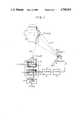
- FIG. 1shows a fucctional structure of a system for measuring the surface profile of a target by a light beam consisting of slit-ray.
- the laser beam from laser source 1is perpendicularly magnified by a lens system 2 including a cylindrical lens and constitutes slit-ray, which is projected onto the surface of a target 4 through a polygonal mirror 3.
- the slit-rayis deflected by projection angle sequentially by the rotation of the polygonal mirror 3, as shown in FIG. 1, whereby the surface of the target 4 is stroked over.
- the deflection angle of the slit-rayis definitely determined by the rotational angle of the polygonal mirror. Therefore, the slit-ray may be identified by directly measuring the rotational angle of the polygonal mirror.
- the polygonal mirroris ordinarily controlled to have rotational movement at a constant angular velocity and the slit-ray is thereby also deflected for scanning at a constant angular velocity and the slit-ray is thereby also deflected for scanning at a constant angular velocity ⁇
- it is possible to identify the slit-rayby measuring the elapsed time t from a reset (trigger) signal 6 which is output when the slit-ray passes a certain reference position. Since the identifying information on the slit-ray deflected in this way is dependent upon the time t, the time t is represented as the identifying information on the slit-ray and is used in the later calculation.
- the slit-ray itselfis represented by n(t) in FIG. 1.
- a photosensor 5such as a phototransistor is provided for detecting a reference position, and when the slit-ray passes across the photosensor 5, the reset (trigger) sigaal 6 is output, which triggers a timer 7 and a clock counter 8.
- the clock counter 8outputs a signal representing the elapsed time t which gives the identifying information on the slit-ray n(t) in real time.
- the deflection angle of the slit-ray n(t) which strokes over the surface of the target 4is specified by the identiyying information of the elapsed time t.
- the reflected light which is reflected from the surface of the target 4is received by an imaging device 9, and the slit-like optical image of the surface of the target 4 which corresponds to the slit-ray n(t) is formed on the imaging plane 11 of an image sensor 10.
- the image sensor 10is composed of a non-scanning image sensor such as a picture synchronous image sensor, and the imaging plane 11 is composed of mutually independent one-dimensionally or two-dimensionally arrayed separate photosensors. Each photosensor corresponds to each picture element. Since the image information on the imaging plane 11 is individually detected for each picture element, parallel processing is enabled. Therefore, when the slit-like optical image moves on the imaging plane 11, it is possible to detect the positional information on the entire slit-like optical iaage, for example, all the addresses of the picture elements corresponding to the slit-like optical image, simultaneously and in real time, on the basis of the output signal supplied when each photosensor on the imaging plane 11 receives the light caused by the optical image.
- a non-scanning image sensorsuch as a picture synchronous image sensor
- the imaging plane 11is composed of mutually independent one-dimensionally or two-dimensionally arrayed separate photosensors. Each photosensor corresponds to each picture element. Since the image information on the imaging plane 11 is individually detected for each
- the positional information on the optical image of the surface of the target 4is detected without electrically scanning the imaging plane 11 each time as in the prior art.
- the identifying information t on the slit-ray n(t) detected in the above-described way and the corresponding positional information on the imaging plane 11 on the optical image of the surface of the targetare coordinatingly latched in a memory unit 12 of the image sensor 10, and is operated by a combine processing part 13 to be converted to the space coordinates of the surface of the target.
- the present inventionit is possible to coordinatingly detect both the identifying information t on the slit-ray n(t) and the corresponding positional information on the slit-like optical image in real time, and thereby to measure the surface profile of the object 4 at a high speed.
- the surface profile of the objcct 4 in the embodiment shown in FIG. 1is specified from the identifying information on the slit-ray and the positional information on the optical image.
- the geo-optical relationship between the slit-ray n(t) reflected from the center M (xm, ym, zm) of mirror reflection shown in FIG. 1, the point P (X, Y, Z) on the surface of the target 4 which is irradiated with the slit-ray n(t), and the optical image I (x, 0, zi) on the imaging planeis projected on the plane xy (FIG. 2) and the plane xz (FIG. 3).
- the solid lines in FIGS. 2 and 3denote a state in which the target is scanned with a single slit beam by using a single light projection device
- the dot-dashed linesdenote a state in which the target is scanned with a second slit-ray beam by providing a second light projection device at a different position from that of the first one.
- the origin of the orthogonal coordinate system (x, y, z)is set, for example, at the center 0 of the imaging plane 11, the axis x is set in the horizontal direction and in parallel to the imaging plane 11, the axis y is set in coincidence with the optical axis and the axis z is perpendicular to the xy plane.
- the coordinate value (X, Y, Z) of the point P on the surface of the target 4is specified by the slit-ray n(t) and the reflected light R(t), as shown in the drawings, and is obtained in the following way by using the coordinate values of the positions of the lens L and the mirror M, and the angular velocity ⁇ of the slit-ray, all of which are set as the measuring conditinns, and the identifying information t on the slit-ray n(t) and the coordinate value (xi, 0, zi) of the optical image I of the point P, all of which are obtained as the results of measurement:
- P.D.the reference point of a light beam (the position of counter set timing)
- ⁇ 0 , ⁇ 0'the angle between the reference position of the slit-ray and the axis x
- ⁇ , ⁇ 'the angular velocity of the slit-ray
- subscript xy, subscript xzthe projected point of each of the points L, M, M', P, P', I' I on the plane xy and the plane xz, respectively ##EQU1##
- the three-dimensional coordinate value (X, Y, Z) at the point P on the surface of the target 4is determined by both the identifying information on the slit-ray n(t), namely, the elapsed time t from a predetermined reset timing and the positional information (xi, 0, zi) on the optical image I on the imaging plane 11.
- FIG. 4shows an example of a non-scanning type image sensor for latching and storing the identifying information on the slit-ray n(t) and the positional information on the optical image on the imaging plane 11 of the image sensor 10.
- the non-scanning type image sensoris composed of the imaging plane 11 and the memory unit 12.
- the imaging plane 11is composed of a plurality of mutually independent arrayed phototransistors 15.
- the light reflected from the target 4is received by the imaging device 9, and the optical image of the surface of the target 4 is formed on one of the phototransistors 15 on the imaging plane 11.
- the light response output of the phototransistor 15is supplied to the memory unit 12.
- the memory unit 12is composed of storage cells 16 arranged in correspondence with respective phototransistors 15 on the imaging plane 11.
- Each of the storage cells 16 of the memory unit 12is composed of, for example, D type flip-flops of a plurality of bits or shift registers.
- the memrry unit 12may also be composed of analog storage cells.
- the storage cell 16is provided in correspondence with the phototransistor 15, and into its write control input terminal is input a light response output from the corresponding phototransistor 15. Further, the identifying information 14 on the slit-ray n(t) is input to a data input bus 17 of the storage cell 16.
- the identifying information 14consists of the output of the counter 8 which starts counting in accordance with the set trigger signal 6 obtained from the light projection device.
- the counter 8starts to count from the initial position of the polygonal mirror 3, and the elapsed time signal t, which is the output of the counter 8, is supplied from the input bus 17 to each storage cell 16 as the identifying information on the slit-ray n(t).
- the phototransistor 15 on which the optical image is formedoutputs a light response signal, and triggers the corresponding storage cell 16.
- the thus-triggered storage cell 16latches the corresponding elapsed time as the identifying information on the slit-ray n(t).
- each identifying information on the slit-ray n(t)is stored and held in the storage cell 16 corresponding to each position of the formed image during scanning.
- the above-described processis a process for storing and holding the identifying information on the slit-ray n(t) coordinatingly with the positional information on the corresponding optical image on the imaging plane.
- this information storing processdoes not include any process for electrically scanning the image sensor unlike the prior art, it is quite possible for the scanning of the surface of the target to catch up with high-speed scanning of the surface of the target 4 with the slit-ray.
- the data stored in this wayare read from each storage cell 16 by a known method, and is converted to the space coordinates (X, Y, Z) of the surface of the three-dimensional object on the basis of the above-described measuring principle.
- FIG. 5shows another example of the image sensors which resembles the one shown in FIG. 4.
- this image sensormutually nndependent arrayed photodiodes are used.
- the image snnsor 10is composed of arrayed photodiodes 20, the output thereof is amplified by transistors 21.
- Each of the photodiodes 2 and a resistor 22are conneoted to the base and the collector of each transistor 21 in series. The emitter of each transistor 21 is grounded.
- the memory unit 12composed of D type flip-flops or resistors, as is the case that shown in FIG. 4, is coordinatingly connected to each group of the photodiode and transistor, and the collector terminal of the transistor 21 is connected to the write control input terminal of each of the storage cell 16.
- the transistor 21 which is connected to the photodiode 20is switched on, and the output voltage of the collector is changed from the "H" level to the "L” level, whereby the coreesponding storage cell 16 is triggered and the time data representing the identifying information of the slit-ray which is connected to the data input bus 17 is latched and stored, in the same way as in the case shown in FIG. 4.
- both the identifying information on the slit-ray and the positional information on the optical imageare also stored and held without delay and, as a result, it is possible to control the speed of scanning the surface of the target 4 by the slit-ray n(t) at a high speed.
- the non-scanning type image sensors shown in FIGS. 4 and 5can be integrated into IC chips in the present art, and there is every reason to expect a miniaturized image pickup device.
- These photosensor groupis divided into sub-groups in accordance with the row address i, and are selectively energized by a switching element 31 such as a multiplexer.
- a switching element 31such as a multiplexer.
- the divided sub-groups of photosensorsare selectively energized by the switching element 31, they are controlled by a row address signal which is supplied from a row address signal line 32 to a switching element 31.
- the output terminals of the photosensors of a sub-group having the same column address jare connected to a common output line 33.
- N sub-groups of photosensors having the same column address jare formed by N common output lines 33.
- the outputs of the photosensor sub-groups fetched from the respective common output lines 33are supplied to the write control input terminals of the respective memory units 35 through respective signal processing elements 34.
- the number of the signal processing elements 34 and the memory units 35 providedare respectively N in correspondence with the common output lines 33.
- a row address signalis supplied from the row address signal line 32 to the address bus of the memory unit 35, and a slit-ray identifying signal is suppled to a data bus 36.
- the storage cell which corresponds to the selected row address in the memory unit 35is energized.
- the slit-ray identifying signalwhich is output at the moment when the optical image has passed the picture element photosensor of the row address group which is selectively being energized, is stored and held in the memory unit 35, as described above.
- FIG. 7shows an example of imaging devices adopting an optical fiber which are suitable for the present invention.
- One end surface of each of the optical fibers 51is arrayed on an imaging plane 50, on which the optical image is formed.
- the other end of the optical fiber 51is led to the arranging surface of arrayed photosensors 52.
- the arrayed photosensors 52are actuated by the light introduced through the optical fibers 51.
- the surface of a targetis stroked over by slit-ray, and the positional information on the optical image which moves on the imaging plane with the movement of the scanned light is detected at the real time on the basis of an output signal supplied when each photosensor which constitutes the imaging plane receives the light caused by the optical image, without the need for repeated electrical scanning on the entire imaging plane as in the prior art. It is possible to measure the surface profile of the target at a high speed from this positional information and the identifying information on the slit-ray which is also detected at the real time. Such high-speed scanning of the surface of a target with the slit-ray also enables very accurate profile measurement with respect to a moving target.
Landscapes
- Engineering & Computer Science (AREA)
- Computer Vision & Pattern Recognition (AREA)
- Physics & Mathematics (AREA)
- General Physics & Mathematics (AREA)
- Length Measuring Devices By Optical Means (AREA)
Abstract
Description
O (0, 0, 0)
L (0, y.sub.1, 0)
M (xm, ym, zm)
M' (xm , ym', zm')
P (X, Y, Z)
P' (X', Y', Z')
I (xi, yi, zi)
I' (xi', yi', zi')
I (xi, yi, zi)
I' (xi', yi, zi')
Claims (13)
Applications Claiming Priority (6)
| Application Number | Priority Date | Filing Date | Title |
|---|---|---|---|
| JP60-272254 | 1985-12-03 | ||
| JP60272253AJPS62131674A (en) | 1985-12-03 | 1985-12-03 | Video synchronizing type image pickup element |
| JP60-272253 | 1985-12-03 | ||
| JP27225485 | 1985-12-03 | ||
| JP61271251AJPH0625653B2 (en) | 1985-12-03 | 1986-11-13 | Shape measuring method and device |
| JP61-271251 | 1986-11-13 |
Publications (1)
| Publication Number | Publication Date |
|---|---|
| US4794262Atrue US4794262A (en) | 1988-12-27 |
Family
ID=27335902
Family Applications (1)
| Application Number | Title | Priority Date | Filing Date |
|---|---|---|---|
| US06/934,834Expired - LifetimeUS4794262A (en) | 1985-12-03 | 1986-11-25 | Method and apparatus for measuring profile of three-dimensional object |
Country Status (1)
| Country | Link |
|---|---|
| US (1) | US4794262A (en) |
Cited By (144)
| Publication number | Priority date | Publication date | Assignee | Title |
|---|---|---|---|---|
| US4894551A (en)* | 1987-06-05 | 1990-01-16 | Anima Corporation | Sectional form measuring apparatus |
| US4900146A (en)* | 1988-03-18 | 1990-02-13 | General Electric Company | Multiple channel optical flying spot triangulation ranger system |
| US4937766A (en)* | 1986-07-23 | 1990-06-26 | Mannesmann Ag | Acquiring dimensions of a large object |
| US4982102A (en)* | 1989-06-27 | 1991-01-01 | Mitsubishi Denki Kabushiki Kaisha | Apparatus for detecting three-dimensional configuration of object employing optical cutting method |
| US4993835A (en)* | 1989-06-16 | 1991-02-19 | Mitsubishi Denki Kabushiki Kaisha | Apparatus for detecting three-dimensional configuration of object employing optical cutting method |
| EP0391532A3 (en)* | 1989-04-05 | 1991-02-27 | Nkk Corporation | Apparatus for measuring three-dimensional curved surface shapes |
| US5046851A (en)* | 1987-03-18 | 1991-09-10 | Davy Mckee (Poole) Limited | Position sensing method and apparatus |
| US5056914A (en)* | 1990-07-12 | 1991-10-15 | Ball Corporation | Charge integration range detector |
| US5061860A (en)* | 1988-06-22 | 1991-10-29 | Hamamatsu Photonics Kabushiki Kaisha | Deformation measuring method and device using comb-type photosensitive element array |
| US5102223A (en)* | 1988-03-31 | 1992-04-07 | Nkk Corporation | Method and apparatus for measuring a three-dimensional curved surface shape |
| US5129010A (en)* | 1989-12-15 | 1992-07-07 | Kabushiki Kaisha Toyoto Chuo Kenkyusho | System for measuring shapes and dimensions of gaps and flushnesses on three dimensional surfaces of objects |
| US5168217A (en)* | 1990-05-10 | 1992-12-01 | Matsushita Electric Industrial Co., Ltd. | Method of detecting floated lead of electrical component |
| US5172001A (en)* | 1989-01-30 | 1992-12-15 | Aeroel S.R.L. | System to automatically compensate the transversal oscillation of the scanning plane in a laser scanner used for profile measurement using reference element |
| EP0462289A4 (en)* | 1989-12-28 | 1993-02-24 | Kabushiki Kaisha Toyota Chuo Kenkyusho | Apparatus for measuring three-dimensional coordinate |
| US5198877A (en)* | 1990-10-15 | 1993-03-30 | Pixsys, Inc. | Method and apparatus for three-dimensional non-contact shape sensing |
| US5243665A (en)* | 1990-03-07 | 1993-09-07 | Fmc Corporation | Component surface distortion evaluation apparatus and method |
| US5280436A (en)* | 1990-04-18 | 1994-01-18 | Matsushita Electric Industrial Co., Ltd. | Method for measuring three-dimensional position of object to be captured and method for capturing the object |
| US5381235A (en)* | 1991-12-26 | 1995-01-10 | Mitsubishi Denki Kabushiki Kaisha | Three-dimensional shape measuring device and three-dimensional shape measuring sensor |
| US5383454A (en)* | 1990-10-19 | 1995-01-24 | St. Louis University | System for indicating the position of a surgical probe within a head on an image of the head |
| US5408324A (en)* | 1992-03-19 | 1995-04-18 | Sony Corporation | Distance measuring method and apparatus that compares signals from plural photocells |
| US5414647A (en)* | 1992-11-23 | 1995-05-09 | Ford Motor Company | Non-contact method and system for building CAD models by integrating high density data scans |
| US5436727A (en)* | 1993-03-08 | 1995-07-25 | Sony Corporation | Distance measuring method and apparatus |
| EP0608634A3 (en)* | 1993-01-12 | 1995-09-06 | Toshiba Kk | Surface shape measurement device. |
| FR2718521A1 (en)* | 1994-04-08 | 1995-10-13 | Cabloptic Sa | Dimension and surface variation detection of fibres & tubes |
| WO1996025764A1 (en)* | 1995-02-16 | 1996-08-22 | Environmental Research Institute Of Michigan | System and method for three-dimensional imaging of opaque objects |
| US5568258A (en)* | 1992-08-25 | 1996-10-22 | Asahi Glass Company Ltd. | Method and device for measuring distortion of a transmitting beam or a surface shape of a three-dimensional object |
| US5661561A (en)* | 1995-06-02 | 1997-08-26 | Accu-Sort Systems, Inc. | Dimensioning system |
| US5668631A (en)* | 1993-12-20 | 1997-09-16 | Minolta Co., Ltd. | Measuring system with improved method of reading image data of an object |
| WO1998002764A1 (en)* | 1996-07-12 | 1998-01-22 | Real-Time Geometry Corporation | Portable 3-d scanning system and method for rapid shape digitizing and adaptive mesh generation |
| US5748767A (en)* | 1988-02-01 | 1998-05-05 | Faro Technology, Inc. | Computer-aided surgery apparatus |
| US5747822A (en)* | 1994-10-26 | 1998-05-05 | Georgia Tech Research Corporation | Method and apparatus for optically digitizing a three-dimensional object |
| US5800352A (en)* | 1994-09-15 | 1998-09-01 | Visualization Technology, Inc. | Registration system for use with position tracking and imaging system for use in medical applications |
| US5829444A (en)* | 1994-09-15 | 1998-11-03 | Visualization Technology, Inc. | Position tracking and imaging system for use in medical applications |
| US5850289A (en)* | 1994-08-24 | 1998-12-15 | Tricorder Technology Plc | Scanning arrangement and method |
| US5848967A (en)* | 1991-01-28 | 1998-12-15 | Cosman; Eric R. | Optically coupled frameless stereotactic system and method |
| US5871445A (en)* | 1993-04-26 | 1999-02-16 | St. Louis University | System for indicating the position of a surgical probe within a head on an image of the head |
| US5969822A (en)* | 1994-09-28 | 1999-10-19 | Applied Research Associates Nz Ltd. | Arbitrary-geometry laser surface scanner |
| US6006126A (en)* | 1991-01-28 | 1999-12-21 | Cosman; Eric R. | System and method for stereotactic registration of image scan data |
| US6044170A (en)* | 1996-03-21 | 2000-03-28 | Real-Time Geometry Corporation | System and method for rapid shape digitizing and adaptive mesh generation |
| US6049385A (en)* | 1996-06-05 | 2000-04-11 | Minolta Co., Ltd. | Three dimensional measurement system and pickup apparatus |
| US6128405A (en)* | 1996-08-30 | 2000-10-03 | Minolta Co., Ltd. | System for processing three-dimensional shape data |
| US6141105A (en)* | 1995-11-17 | 2000-10-31 | Minolta Co., Ltd. | Three-dimensional measuring device and three-dimensional measuring method |
| US6146390A (en)* | 1992-04-21 | 2000-11-14 | Sofamor Danek Holdings, Inc. | Apparatus and method for photogrammetric surgical localization |
| US6151118A (en)* | 1996-11-19 | 2000-11-21 | Minolta Co., Ltd | Three-dimensional measuring system and method of measuring the shape of an object |
| US6167295A (en)* | 1991-01-28 | 2000-12-26 | Radionics, Inc. | Optical and computer graphic stereotactic localizer |
| US6167145A (en)* | 1996-03-29 | 2000-12-26 | Surgical Navigation Technologies, Inc. | Bone navigation system |
| US6233049B1 (en)* | 1998-03-25 | 2001-05-15 | Minolta Co., Ltd. | Three-dimensional measurement apparatus |
| US6236875B1 (en) | 1994-10-07 | 2001-05-22 | Surgical Navigation Technologies | Surgical navigation systems including reference and localization frames |
| US6268918B1 (en)* | 1998-06-18 | 2001-07-31 | Minolta Co., Ltd. | Three-dimensional input device |
| US6296613B1 (en) | 1997-08-22 | 2001-10-02 | Synthes (U.S.A.) | 3D ultrasound recording device |
| US6347240B1 (en) | 1990-10-19 | 2002-02-12 | St. Louis University | System and method for use in displaying images of a body part |
| US20020050988A1 (en)* | 2000-03-28 | 2002-05-02 | Michael Petrov | System and method of three-dimensional image capture and modeling |
| US6405072B1 (en) | 1991-01-28 | 2002-06-11 | Sherwood Services Ag | Apparatus and method for determining a location of an anatomical target with reference to a medical apparatus |
| US6407817B1 (en)* | 1993-12-20 | 2002-06-18 | Minolta Co., Ltd. | Measuring system with improved method of reading image data of an object |
| US6421629B1 (en)* | 1999-04-30 | 2002-07-16 | Nec Corporation | Three-dimensional shape measurement method and apparatus and computer program product |
| US6421132B1 (en) | 1999-10-15 | 2002-07-16 | Vladimir M. Brajovic | Method and apparatus for rapid range imaging |
| US6424877B1 (en) | 1997-04-04 | 2002-07-23 | Minolta Co., Ltd. | Reproduction apparatus |
| US6448572B1 (en)* | 1999-09-29 | 2002-09-10 | Innovative Technology Licensing, Llc | Ranging three-dimensional laser imager and method |
| US6470293B1 (en)* | 1998-09-02 | 2002-10-22 | Casio Computer Co., Ltd. | Volume calculating apparatus and storage medium |
| US6549288B1 (en) | 1998-05-14 | 2003-04-15 | Viewpoint Corp. | Structured-light, triangulation-based three-dimensional digitizer |
| US6585651B2 (en) | 1999-04-20 | 2003-07-01 | Synthes Ag Chur | Method and device for percutaneous determination of points associated with the surface of an organ |
| WO2003065886A1 (en)* | 2002-02-05 | 2003-08-14 | Technische Universität Ilmenau | Method and arrangement for the contactless determination of the direction of viewing |
| US6675040B1 (en) | 1991-01-28 | 2004-01-06 | Sherwood Services Ag | Optical object tracking system |
| US6674893B1 (en)* | 1999-10-19 | 2004-01-06 | Fuji Xerox Co., Ltd. | Three-dimensional shape measuring apparatus |
| US6694168B2 (en) | 1998-06-22 | 2004-02-17 | Synthes (U.S.A.) | Fiducial matching using fiducial implants |
| US6725082B2 (en) | 1999-03-17 | 2004-04-20 | Synthes U.S.A. | System and method for ligament graft placement |
| US6763133B1 (en)* | 1999-05-29 | 2004-07-13 | Sun Moon University | Moire image capturing apparatus and method therefor |
| US6798528B1 (en) | 2000-09-20 | 2004-09-28 | Richard L. Hartman | System and method for measuring the dimensions of moving packages |
| US6888640B2 (en) | 2000-02-04 | 2005-05-03 | Mario J. Spina | Body spatial dimension mapper |
| US6978166B2 (en) | 1994-10-07 | 2005-12-20 | Saint Louis University | System for use in displaying images of a body part |
| US7002623B1 (en)* | 1998-09-08 | 2006-02-21 | Olympus Optical Co., Ltd. | Image processing apparatus for correcting a color and texture of an image and displaying the corrected image |
| US20060188133A1 (en)* | 2003-01-13 | 2006-08-24 | Schallig Michiel A A | Method of and apparatus for determing height or profile of an object |
| US7217276B2 (en) | 1999-04-20 | 2007-05-15 | Surgical Navigational Technologies, Inc. | Instrument guidance method and system for image guided surgery |
| US7277594B2 (en) | 1999-05-03 | 2007-10-02 | Ao Technology Ag | System and method for preparing an image corrected for the presence of a gravity induced distortion |
| US20070273687A1 (en)* | 2003-10-15 | 2007-11-29 | Ron Daniel | Device for Scanning Three-Dimensional Objects |
| US20070288135A1 (en)* | 2006-06-08 | 2007-12-13 | Kidd Scott D | Method and apparatus for obtaining photogrammetric data to estimate impact severity |
| US7313430B2 (en) | 2003-08-28 | 2007-12-25 | Medtronic Navigation, Inc. | Method and apparatus for performing stereotactic surgery |
| US7366562B2 (en) | 2003-10-17 | 2008-04-29 | Medtronic Navigation, Inc. | Method and apparatus for surgical navigation |
| US7542791B2 (en) | 2003-01-30 | 2009-06-02 | Medtronic Navigation, Inc. | Method and apparatus for preplanning a surgical procedure |
| US7567834B2 (en) | 2004-05-03 | 2009-07-28 | Medtronic Navigation, Inc. | Method and apparatus for implantation between two vertebral bodies |
| US7570791B2 (en) | 2003-04-25 | 2009-08-04 | Medtronic Navigation, Inc. | Method and apparatus for performing 2D to 3D registration |
| US7599730B2 (en) | 2002-11-19 | 2009-10-06 | Medtronic Navigation, Inc. | Navigation system for cardiac therapies |
| US7606613B2 (en) | 1999-03-23 | 2009-10-20 | Medtronic Navigation, Inc. | Navigational guidance via computer-assisted fluoroscopic imaging |
| US7630753B2 (en) | 2002-02-28 | 2009-12-08 | Medtronic Navigation, Inc. | Method and apparatus for perspective inversion |
| US7636595B2 (en) | 2004-10-28 | 2009-12-22 | Medtronic Navigation, Inc. | Method and apparatus for calibrating non-linear instruments |
| US7657300B2 (en) | 1999-10-28 | 2010-02-02 | Medtronic Navigation, Inc. | Registration of human anatomy integrated for electromagnetic localization |
| US7660623B2 (en) | 2003-01-30 | 2010-02-09 | Medtronic Navigation, Inc. | Six degree of freedom alignment display for medical procedures |
| US7697972B2 (en) | 2002-11-19 | 2010-04-13 | Medtronic Navigation, Inc. | Navigation system for cardiac therapies |
| US7763035B2 (en) | 1997-12-12 | 2010-07-27 | Medtronic Navigation, Inc. | Image guided spinal surgery guide, system and method for use thereof |
| US7797032B2 (en) | 1999-10-28 | 2010-09-14 | Medtronic Navigation, Inc. | Method and system for navigating a catheter probe in the presence of field-influencing objects |
| US7831082B2 (en) | 2000-06-14 | 2010-11-09 | Medtronic Navigation, Inc. | System and method for image based sensor calibration |
| US7835784B2 (en) | 2005-09-21 | 2010-11-16 | Medtronic Navigation, Inc. | Method and apparatus for positioning a reference frame |
| US7835778B2 (en) | 2003-10-16 | 2010-11-16 | Medtronic Navigation, Inc. | Method and apparatus for surgical navigation of a multiple piece construct for implantation |
| US7840253B2 (en) | 2003-10-17 | 2010-11-23 | Medtronic Navigation, Inc. | Method and apparatus for surgical navigation |
| US7853305B2 (en) | 2000-04-07 | 2010-12-14 | Medtronic Navigation, Inc. | Trajectory storage apparatus and method for surgical navigation systems |
| US7881770B2 (en) | 2000-03-01 | 2011-02-01 | Medtronic Navigation, Inc. | Multiple cannula image guided tool for image guided procedures |
| USRE42194E1 (en) | 1997-09-24 | 2011-03-01 | Medtronic Navigation, Inc. | Percutaneous registration apparatus and method for use in computer-assisted surgical navigation |
| US7998062B2 (en) | 2004-03-29 | 2011-08-16 | Superdimension, Ltd. | Endoscope structures and techniques for navigating to a target in branched structure |
| US8057407B2 (en) | 1999-10-28 | 2011-11-15 | Medtronic Navigation, Inc. | Surgical sensor |
| US8074662B2 (en) | 1999-10-28 | 2011-12-13 | Medtronic Navigation, Inc. | Surgical communication and power system |
| US8112292B2 (en) | 2006-04-21 | 2012-02-07 | Medtronic Navigation, Inc. | Method and apparatus for optimizing a therapy |
| US8165658B2 (en) | 2008-09-26 | 2012-04-24 | Medtronic, Inc. | Method and apparatus for positioning a guide relative to a base |
| USRE43328E1 (en) | 1997-11-20 | 2012-04-24 | Medtronic Navigation, Inc | Image guided awl/tap/screwdriver |
| US8175681B2 (en) | 2008-12-16 | 2012-05-08 | Medtronic Navigation Inc. | Combination of electromagnetic and electropotential localization |
| US8200314B2 (en) | 1992-08-14 | 2012-06-12 | British Telecommunications Public Limited Company | Surgical navigation |
| US8239001B2 (en) | 2003-10-17 | 2012-08-07 | Medtronic Navigation, Inc. | Method and apparatus for surgical navigation |
| USRE43952E1 (en) | 1989-10-05 | 2013-01-29 | Medtronic Navigation, Inc. | Interactive system for local intervention inside a non-homogeneous structure |
| US8452068B2 (en) | 2008-06-06 | 2013-05-28 | Covidien Lp | Hybrid registration method |
| US8473032B2 (en) | 2008-06-03 | 2013-06-25 | Superdimension, Ltd. | Feature-based registration method |
| US8494613B2 (en) | 2009-08-31 | 2013-07-23 | Medtronic, Inc. | Combination localization system |
| US8494614B2 (en) | 2009-08-31 | 2013-07-23 | Regents Of The University Of Minnesota | Combination localization system |
| US8611984B2 (en) | 2009-04-08 | 2013-12-17 | Covidien Lp | Locatable catheter |
| US8644907B2 (en) | 1999-10-28 | 2014-02-04 | Medtronic Navigaton, Inc. | Method and apparatus for surgical navigation |
| US8660635B2 (en) | 2006-09-29 | 2014-02-25 | Medtronic, Inc. | Method and apparatus for optimizing a computer assisted surgical procedure |
| US8663088B2 (en) | 2003-09-15 | 2014-03-04 | Covidien Lp | System of accessories for use with bronchoscopes |
| US8764725B2 (en) | 2004-02-09 | 2014-07-01 | Covidien Lp | Directional anchoring mechanism, method and applications thereof |
| US8768437B2 (en) | 1998-08-20 | 2014-07-01 | Sofamor Danek Holdings, Inc. | Fluoroscopic image guided surgery system with intraoperative registration |
| US8838199B2 (en) | 2002-04-04 | 2014-09-16 | Medtronic Navigation, Inc. | Method and apparatus for virtual digital subtraction angiography |
| US8905920B2 (en) | 2007-09-27 | 2014-12-09 | Covidien Lp | Bronchoscope adapter and method |
| US8932207B2 (en) | 2008-07-10 | 2015-01-13 | Covidien Lp | Integrated multi-functional endoscopic tool |
| US9055881B2 (en) | 2004-04-26 | 2015-06-16 | Super Dimension Ltd. | System and method for image-based alignment of an endoscope |
| US9163936B1 (en)* | 2012-05-07 | 2015-10-20 | Physical Optics Corporation | Three-dimensional profilometer |
| US9168102B2 (en) | 2006-01-18 | 2015-10-27 | Medtronic Navigation, Inc. | Method and apparatus for providing a container to a sterile environment |
| US20160063716A1 (en)* | 2014-08-29 | 2016-03-03 | Leica Geosystems Ag | Line parametric object estimation |
| US9575140B2 (en) | 2008-04-03 | 2017-02-21 | Covidien Lp | Magnetic interference detection system and method |
| US9675424B2 (en) | 2001-06-04 | 2017-06-13 | Surgical Navigation Technologies, Inc. | Method for calibrating a navigation system |
| US10418705B2 (en) | 2016-10-28 | 2019-09-17 | Covidien Lp | Electromagnetic navigation antenna assembly and electromagnetic navigation system including the same |
| US10426555B2 (en) | 2015-06-03 | 2019-10-01 | Covidien Lp | Medical instrument with sensor for use in a system and method for electromagnetic navigation |
| US10446931B2 (en) | 2016-10-28 | 2019-10-15 | Covidien Lp | Electromagnetic navigation antenna assembly and electromagnetic navigation system including the same |
| US10478254B2 (en) | 2016-05-16 | 2019-11-19 | Covidien Lp | System and method to access lung tissue |
| US10517505B2 (en) | 2016-10-28 | 2019-12-31 | Covidien Lp | Systems, methods, and computer-readable media for optimizing an electromagnetic navigation system |
| US10582834B2 (en) | 2010-06-15 | 2020-03-10 | Covidien Lp | Locatable expandable working channel and method |
| US10615500B2 (en) | 2016-10-28 | 2020-04-07 | Covidien Lp | System and method for designing electromagnetic navigation antenna assemblies |
| US10638952B2 (en) | 2016-10-28 | 2020-05-05 | Covidien Lp | Methods, systems, and computer-readable media for calibrating an electromagnetic navigation system |
| US10722311B2 (en) | 2016-10-28 | 2020-07-28 | Covidien Lp | System and method for identifying a location and/or an orientation of an electromagnetic sensor based on a map |
| US10751126B2 (en) | 2016-10-28 | 2020-08-25 | Covidien Lp | System and method for generating a map for electromagnetic navigation |
| US10792106B2 (en) | 2016-10-28 | 2020-10-06 | Covidien Lp | System for calibrating an electromagnetic navigation system |
| US10952593B2 (en) | 2014-06-10 | 2021-03-23 | Covidien Lp | Bronchoscope adapter |
| US11006914B2 (en) | 2015-10-28 | 2021-05-18 | Medtronic Navigation, Inc. | Apparatus and method for maintaining image quality while minimizing x-ray dosage of a patient |
| US11054249B2 (en)* | 2018-11-09 | 2021-07-06 | Keyence Corporation | Profile measuring apparatus |
| US11219489B2 (en) | 2017-10-31 | 2022-01-11 | Covidien Lp | Devices and systems for providing sensors in parallel with medical tools |
| US20220086404A1 (en)* | 2020-09-17 | 2022-03-17 | Iview Displays (Shenzhen) Company Ltd. | Dynamic projection method for target tracking and a dynamic projection equipment |
| US11331150B2 (en) | 1999-10-28 | 2022-05-17 | Medtronic Navigation, Inc. | Method and apparatus for surgical navigation |
| US12089902B2 (en) | 2019-07-30 | 2024-09-17 | Coviden Lp | Cone beam and 3D fluoroscope lung navigation |
Citations (3)
| Publication number | Priority date | Publication date | Assignee | Title |
|---|---|---|---|---|
| US4472056A (en)* | 1980-07-23 | 1984-09-18 | Hitachi, Ltd. | Shape detecting apparatus |
| US4494874A (en)* | 1981-07-07 | 1985-01-22 | Robotic Vision Systems, Inc. | Detection of three-dimensional information using a projected point or line of light |
| FR2560472A1 (en)* | 1984-02-23 | 1985-08-30 | Proge | FAST PROFILE TAKING DEVICE |
- 1986
- 1986-11-25USUS06/934,834patent/US4794262A/ennot_activeExpired - Lifetime
Patent Citations (3)
| Publication number | Priority date | Publication date | Assignee | Title |
|---|---|---|---|---|
| US4472056A (en)* | 1980-07-23 | 1984-09-18 | Hitachi, Ltd. | Shape detecting apparatus |
| US4494874A (en)* | 1981-07-07 | 1985-01-22 | Robotic Vision Systems, Inc. | Detection of three-dimensional information using a projected point or line of light |
| FR2560472A1 (en)* | 1984-02-23 | 1985-08-30 | Proge | FAST PROFILE TAKING DEVICE |
Cited By (265)
| Publication number | Priority date | Publication date | Assignee | Title |
|---|---|---|---|---|
| US4937766A (en)* | 1986-07-23 | 1990-06-26 | Mannesmann Ag | Acquiring dimensions of a large object |
| US5046851A (en)* | 1987-03-18 | 1991-09-10 | Davy Mckee (Poole) Limited | Position sensing method and apparatus |
| US4894551A (en)* | 1987-06-05 | 1990-01-16 | Anima Corporation | Sectional form measuring apparatus |
| US5748767A (en)* | 1988-02-01 | 1998-05-05 | Faro Technology, Inc. | Computer-aided surgery apparatus |
| US4900146A (en)* | 1988-03-18 | 1990-02-13 | General Electric Company | Multiple channel optical flying spot triangulation ranger system |
| US5102223A (en)* | 1988-03-31 | 1992-04-07 | Nkk Corporation | Method and apparatus for measuring a three-dimensional curved surface shape |
| US5061860A (en)* | 1988-06-22 | 1991-10-29 | Hamamatsu Photonics Kabushiki Kaisha | Deformation measuring method and device using comb-type photosensitive element array |
| US5172001A (en)* | 1989-01-30 | 1992-12-15 | Aeroel S.R.L. | System to automatically compensate the transversal oscillation of the scanning plane in a laser scanner used for profile measurement using reference element |
| EP0391532A3 (en)* | 1989-04-05 | 1991-02-27 | Nkk Corporation | Apparatus for measuring three-dimensional curved surface shapes |
| US5102224A (en)* | 1989-04-05 | 1992-04-07 | Nkk Corporation | Apparatus for measuring three-dimensional curved surface shapes |
| US5104227A (en)* | 1989-04-05 | 1992-04-14 | Nkk Corporation | Apparatus for measuring three-dimensional curved surface shapes |
| US4993835A (en)* | 1989-06-16 | 1991-02-19 | Mitsubishi Denki Kabushiki Kaisha | Apparatus for detecting three-dimensional configuration of object employing optical cutting method |
| US4982102A (en)* | 1989-06-27 | 1991-01-01 | Mitsubishi Denki Kabushiki Kaisha | Apparatus for detecting three-dimensional configuration of object employing optical cutting method |
| USRE43952E1 (en) | 1989-10-05 | 2013-01-29 | Medtronic Navigation, Inc. | Interactive system for local intervention inside a non-homogeneous structure |
| US5129010A (en)* | 1989-12-15 | 1992-07-07 | Kabushiki Kaisha Toyoto Chuo Kenkyusho | System for measuring shapes and dimensions of gaps and flushnesses on three dimensional surfaces of objects |
| EP0462289A4 (en)* | 1989-12-28 | 1993-02-24 | Kabushiki Kaisha Toyota Chuo Kenkyusho | Apparatus for measuring three-dimensional coordinate |
| US5280542A (en)* | 1989-12-28 | 1994-01-18 | Kabushiki Kaisha Toyota Chuo Kenkyusho | XYZ coordinates measuring system |
| US5243665A (en)* | 1990-03-07 | 1993-09-07 | Fmc Corporation | Component surface distortion evaluation apparatus and method |
| US5280436A (en)* | 1990-04-18 | 1994-01-18 | Matsushita Electric Industrial Co., Ltd. | Method for measuring three-dimensional position of object to be captured and method for capturing the object |
| US5168217A (en)* | 1990-05-10 | 1992-12-01 | Matsushita Electric Industrial Co., Ltd. | Method of detecting floated lead of electrical component |
| US5056914A (en)* | 1990-07-12 | 1991-10-15 | Ball Corporation | Charge integration range detector |
| US5198877A (en)* | 1990-10-15 | 1993-03-30 | Pixsys, Inc. | Method and apparatus for three-dimensional non-contact shape sensing |
| USRE35816E (en)* | 1990-10-15 | 1998-06-02 | Image Guided Technologies Inc. | Method and apparatus for three-dimensional non-contact shape sensing |
| US6490467B1 (en) | 1990-10-19 | 2002-12-03 | Surgical Navigation Technologies, Inc. | Surgical navigation systems including reference and localization frames |
| US6434415B1 (en) | 1990-10-19 | 2002-08-13 | St. Louis University | System for use in displaying images of a body part |
| US5891034A (en)* | 1990-10-19 | 1999-04-06 | St. Louis University | System for indicating the position of a surgical probe within a head on an image of the head |
| US6463319B1 (en) | 1990-10-19 | 2002-10-08 | St. Louis University | System for indicating the position of a surgical probe within a head on an image of the head |
| US5383454A (en)* | 1990-10-19 | 1995-01-24 | St. Louis University | System for indicating the position of a surgical probe within a head on an image of the head |
| US6347240B1 (en) | 1990-10-19 | 2002-02-12 | St. Louis University | System and method for use in displaying images of a body part |
| US6076008A (en)* | 1990-10-19 | 2000-06-13 | St. Louis University | System for indicating the position of a surgical probe within a head on an image of the head |
| US5851183A (en)* | 1990-10-19 | 1998-12-22 | St. Louis University | System for indicating the position of a surgical probe within a head on an image of the head |
| US6678545B2 (en) | 1990-10-19 | 2004-01-13 | Saint Louis University | System for determining the position in a scan image corresponding to the position of an imaging probe |
| US20060241400A1 (en)* | 1990-10-19 | 2006-10-26 | St. Louis University | Method of determining the position of an instrument relative to a body of a patient |
| US6374135B1 (en) | 1990-10-19 | 2002-04-16 | Saint Louis University | System for indicating the position of a surgical probe within a head on an image of the head |
| US7072704B2 (en) | 1990-10-19 | 2006-07-04 | St. Louis University | System for indicating the position of a surgical probe within a head on an image of the head |
| US6662036B2 (en) | 1991-01-28 | 2003-12-09 | Sherwood Services Ag | Surgical positioning system |
| US6167295A (en)* | 1991-01-28 | 2000-12-26 | Radionics, Inc. | Optical and computer graphic stereotactic localizer |
| US6675040B1 (en) | 1991-01-28 | 2004-01-06 | Sherwood Services Ag | Optical object tracking system |
| US6351661B1 (en) | 1991-01-28 | 2002-02-26 | Sherwood Services Ag | Optically coupled frameless stereotactic space probe |
| US5848967A (en)* | 1991-01-28 | 1998-12-15 | Cosman; Eric R. | Optically coupled frameless stereotactic system and method |
| US6006126A (en)* | 1991-01-28 | 1999-12-21 | Cosman; Eric R. | System and method for stereotactic registration of image scan data |
| US6405072B1 (en) | 1991-01-28 | 2002-06-11 | Sherwood Services Ag | Apparatus and method for determining a location of an anatomical target with reference to a medical apparatus |
| US6275725B1 (en) | 1991-01-28 | 2001-08-14 | Radionics, Inc. | Stereotactic optical navigation |
| US5381235A (en)* | 1991-12-26 | 1995-01-10 | Mitsubishi Denki Kabushiki Kaisha | Three-dimensional shape measuring device and three-dimensional shape measuring sensor |
| US5408324A (en)* | 1992-03-19 | 1995-04-18 | Sony Corporation | Distance measuring method and apparatus that compares signals from plural photocells |
| US6165181A (en)* | 1992-04-21 | 2000-12-26 | Sofamor Danek Holdings, Inc. | Apparatus and method for photogrammetric surgical localization |
| US6146390A (en)* | 1992-04-21 | 2000-11-14 | Sofamor Danek Holdings, Inc. | Apparatus and method for photogrammetric surgical localization |
| US8200314B2 (en) | 1992-08-14 | 2012-06-12 | British Telecommunications Public Limited Company | Surgical navigation |
| US5568258A (en)* | 1992-08-25 | 1996-10-22 | Asahi Glass Company Ltd. | Method and device for measuring distortion of a transmitting beam or a surface shape of a three-dimensional object |
| US5414647A (en)* | 1992-11-23 | 1995-05-09 | Ford Motor Company | Non-contact method and system for building CAD models by integrating high density data scans |
| EP0608634A3 (en)* | 1993-01-12 | 1995-09-06 | Toshiba Kk | Surface shape measurement device. |
| US5436727A (en)* | 1993-03-08 | 1995-07-25 | Sony Corporation | Distance measuring method and apparatus |
| EP0618461A3 (en)* | 1993-03-08 | 1997-11-19 | Sony Corporation | Distance measuring method and apparatus |
| US5871445A (en)* | 1993-04-26 | 1999-02-16 | St. Louis University | System for indicating the position of a surgical probe within a head on an image of the head |
| US7139601B2 (en) | 1993-04-26 | 2006-11-21 | Surgical Navigation Technologies, Inc. | Surgical navigation systems including reference and localization frames |
| US20020131056A1 (en)* | 1993-12-20 | 2002-09-19 | Eiro Fujii | Measuring system with improved method of reading image data of an object |
| US5668631A (en)* | 1993-12-20 | 1997-09-16 | Minolta Co., Ltd. | Measuring system with improved method of reading image data of an object |
| US6775010B2 (en) | 1993-12-20 | 2004-08-10 | Minolta Co., Ltd. | Measuring system with improved method of reading image data of an object |
| US6674534B2 (en) | 1993-12-20 | 2004-01-06 | Minolta Co., Ltd. | Measuring system with improved method of reading image data of an object |
| US6522412B2 (en) | 1993-12-20 | 2003-02-18 | Minolta Co., Ltd. | Measuring system with improved method of reading image data of an object |
| US6480288B1 (en) | 1993-12-20 | 2002-11-12 | Minolta Co., Ltd. | Measuring system with improved method of reading image data of an object |
| US6407817B1 (en)* | 1993-12-20 | 2002-06-18 | Minolta Co., Ltd. | Measuring system with improved method of reading image data of an object |
| US6243165B1 (en) | 1993-12-20 | 2001-06-05 | Minolta Co., Ltd. | Measuring system with improved method of reading image data of an object |
| FR2718521A1 (en)* | 1994-04-08 | 1995-10-13 | Cabloptic Sa | Dimension and surface variation detection of fibres & tubes |
| US6128086A (en)* | 1994-08-24 | 2000-10-03 | Tricorder Technology Plc | Scanning arrangement and method |
| US5850289A (en)* | 1994-08-24 | 1998-12-15 | Tricorder Technology Plc | Scanning arrangement and method |
| US6694167B1 (en) | 1994-09-15 | 2004-02-17 | Ge Medical Systems Global Technology Company, Llc | System for monitoring a position of a medical instrument with respect to a patient's head |
| US8473026B2 (en) | 1994-09-15 | 2013-06-25 | Ge Medical Systems Global Technology Company | System for monitoring a position of a medical instrument with respect to a patient's body |
| US6738656B1 (en) | 1994-09-15 | 2004-05-18 | Ge Medical Systems Global Technology Company, Llc | Automatic registration system for use with position tracking an imaging system for use in medical applications |
| US6341231B1 (en) | 1994-09-15 | 2002-01-22 | Visualization Technology, Inc. | Position tracking and imaging system for use in medical applications |
| US6687531B1 (en) | 1994-09-15 | 2004-02-03 | Ge Medical Systems Global Technology Company, Llc | Position tracking and imaging system for use in medical applications |
| US5800352A (en)* | 1994-09-15 | 1998-09-01 | Visualization Technology, Inc. | Registration system for use with position tracking and imaging system for use in medical applications |
| US5967980A (en)* | 1994-09-15 | 1999-10-19 | Visualization Technology, Inc. | Position tracking and imaging system for use in medical applications |
| US5829444A (en)* | 1994-09-15 | 1998-11-03 | Visualization Technology, Inc. | Position tracking and imaging system for use in medical applications |
| US6175756B1 (en) | 1994-09-15 | 2001-01-16 | Visualization Technology Inc. | Position tracking and imaging system for use in medical applications |
| US6934575B2 (en) | 1994-09-15 | 2005-08-23 | Ge Medical Systems Global Technology Company, Llc | Position tracking and imaging system for use in medical applications |
| US5873822A (en)* | 1994-09-15 | 1999-02-23 | Visualization Technology, Inc. | Automatic registration system for use with position tracking and imaging system for use in medical applications |
| US6445943B1 (en) | 1994-09-15 | 2002-09-03 | Visualization Technology, Inc. | Position tracking and imaging system for use in medical applications |
| US5969822A (en)* | 1994-09-28 | 1999-10-19 | Applied Research Associates Nz Ltd. | Arbitrary-geometry laser surface scanner |
| US8046053B2 (en) | 1994-10-07 | 2011-10-25 | Foley Kevin T | System and method for modifying images of a body part |
| US6978166B2 (en) | 1994-10-07 | 2005-12-20 | Saint Louis University | System for use in displaying images of a body part |
| US6236875B1 (en) | 1994-10-07 | 2001-05-22 | Surgical Navigation Technologies | Surgical navigation systems including reference and localization frames |
| US5747822A (en)* | 1994-10-26 | 1998-05-05 | Georgia Tech Research Corporation | Method and apparatus for optically digitizing a three-dimensional object |
| WO1996025764A1 (en)* | 1995-02-16 | 1996-08-22 | Environmental Research Institute Of Michigan | System and method for three-dimensional imaging of opaque objects |
| US5661561A (en)* | 1995-06-02 | 1997-08-26 | Accu-Sort Systems, Inc. | Dimensioning system |
| US5969823A (en)* | 1995-06-02 | 1999-10-19 | Accu-Sort Systems, Inc. | Dimensioning system |
| US6775012B2 (en) | 1995-06-02 | 2004-08-10 | Accu-Sort Systems, Inc. | System for dimensioning objects using at least one light beam offset relative to a perpendicular from an object supporting surface |
| US6177999B1 (en) | 1995-06-02 | 2001-01-23 | Accu-Sort Systems, Inc. | Dimensioning system |
| US6529280B1 (en) | 1995-11-17 | 2003-03-04 | Minolta Co., Ltd. | Three-dimensional measuring device and three-dimensional measuring method |
| US6141105A (en)* | 1995-11-17 | 2000-10-31 | Minolta Co., Ltd. | Three-dimensional measuring device and three-dimensional measuring method |
| US6044170A (en)* | 1996-03-21 | 2000-03-28 | Real-Time Geometry Corporation | System and method for rapid shape digitizing and adaptive mesh generation |
| US6167145A (en)* | 1996-03-29 | 2000-12-26 | Surgical Navigation Technologies, Inc. | Bone navigation system |
| US6172755B1 (en) | 1996-06-05 | 2001-01-09 | Minolta Company, Ltd. | Three dimensional measurement system and pickup apparatus |
| US6049385A (en)* | 1996-06-05 | 2000-04-11 | Minolta Co., Ltd. | Three dimensional measurement system and pickup apparatus |
| US5870220A (en)* | 1996-07-12 | 1999-02-09 | Real-Time Geometry Corporation | Portable 3-D scanning system and method for rapid shape digitizing and adaptive mesh generation |
| WO1998002764A1 (en)* | 1996-07-12 | 1998-01-22 | Real-Time Geometry Corporation | Portable 3-d scanning system and method for rapid shape digitizing and adaptive mesh generation |
| US6128405A (en)* | 1996-08-30 | 2000-10-03 | Minolta Co., Ltd. | System for processing three-dimensional shape data |
| US6151118A (en)* | 1996-11-19 | 2000-11-21 | Minolta Co., Ltd | Three-dimensional measuring system and method of measuring the shape of an object |
| US6424877B1 (en) | 1997-04-04 | 2002-07-23 | Minolta Co., Ltd. | Reproduction apparatus |
| US6296613B1 (en) | 1997-08-22 | 2001-10-02 | Synthes (U.S.A.) | 3D ultrasound recording device |
| USRE42194E1 (en) | 1997-09-24 | 2011-03-01 | Medtronic Navigation, Inc. | Percutaneous registration apparatus and method for use in computer-assisted surgical navigation |
| USRE42226E1 (en) | 1997-09-24 | 2011-03-15 | Medtronic Navigation, Inc. | Percutaneous registration apparatus and method for use in computer-assisted surgical navigation |
| USRE44305E1 (en) | 1997-09-24 | 2013-06-18 | Medtronic Navigation, Inc. | Percutaneous registration apparatus and method for use in computer-assisted surgical navigation |
| USRE46409E1 (en) | 1997-11-20 | 2017-05-23 | Medtronic Navigation, Inc. | Image guided awl/tap/screwdriver |
| USRE43328E1 (en) | 1997-11-20 | 2012-04-24 | Medtronic Navigation, Inc | Image guided awl/tap/screwdriver |
| USRE46422E1 (en) | 1997-11-20 | 2017-06-06 | Medtronic Navigation, Inc. | Image guided awl/tap/screwdriver |
| US7763035B2 (en) | 1997-12-12 | 2010-07-27 | Medtronic Navigation, Inc. | Image guided spinal surgery guide, system and method for use thereof |
| US8105339B2 (en) | 1997-12-12 | 2012-01-31 | Sofamor Danek Holdings, Inc. | Image guided spinal surgery guide system and method for use thereof |
| US6233049B1 (en)* | 1998-03-25 | 2001-05-15 | Minolta Co., Ltd. | Three-dimensional measurement apparatus |
| US6549288B1 (en) | 1998-05-14 | 2003-04-15 | Viewpoint Corp. | Structured-light, triangulation-based three-dimensional digitizer |
| US6268918B1 (en)* | 1998-06-18 | 2001-07-31 | Minolta Co., Ltd. | Three-dimensional input device |
| US6694168B2 (en) | 1998-06-22 | 2004-02-17 | Synthes (U.S.A.) | Fiducial matching using fiducial implants |
| US8768437B2 (en) | 1998-08-20 | 2014-07-01 | Sofamor Danek Holdings, Inc. | Fluoroscopic image guided surgery system with intraoperative registration |
| US6470293B1 (en)* | 1998-09-02 | 2002-10-22 | Casio Computer Co., Ltd. | Volume calculating apparatus and storage medium |
| US7002623B1 (en)* | 1998-09-08 | 2006-02-21 | Olympus Optical Co., Ltd. | Image processing apparatus for correcting a color and texture of an image and displaying the corrected image |
| US6725082B2 (en) | 1999-03-17 | 2004-04-20 | Synthes U.S.A. | System and method for ligament graft placement |
| US7606613B2 (en) | 1999-03-23 | 2009-10-20 | Medtronic Navigation, Inc. | Navigational guidance via computer-assisted fluoroscopic imaging |
| US7996064B2 (en) | 1999-03-23 | 2011-08-09 | Medtronic Navigation, Inc. | System and method for placing and determining an appropriately sized surgical implant |
| US6585651B2 (en) | 1999-04-20 | 2003-07-01 | Synthes Ag Chur | Method and device for percutaneous determination of points associated with the surface of an organ |
| US7217276B2 (en) | 1999-04-20 | 2007-05-15 | Surgical Navigational Technologies, Inc. | Instrument guidance method and system for image guided surgery |
| US8845655B2 (en) | 1999-04-20 | 2014-09-30 | Medtronic Navigation, Inc. | Instrument guide system |
| US6421629B1 (en)* | 1999-04-30 | 2002-07-16 | Nec Corporation | Three-dimensional shape measurement method and apparatus and computer program product |
| US7277594B2 (en) | 1999-05-03 | 2007-10-02 | Ao Technology Ag | System and method for preparing an image corrected for the presence of a gravity induced distortion |
| US6763133B1 (en)* | 1999-05-29 | 2004-07-13 | Sun Moon University | Moire image capturing apparatus and method therefor |
| US6448572B1 (en)* | 1999-09-29 | 2002-09-10 | Innovative Technology Licensing, Llc | Ranging three-dimensional laser imager and method |
| US6421132B1 (en) | 1999-10-15 | 2002-07-16 | Vladimir M. Brajovic | Method and apparatus for rapid range imaging |
| US6674893B1 (en)* | 1999-10-19 | 2004-01-06 | Fuji Xerox Co., Ltd. | Three-dimensional shape measuring apparatus |
| US7657300B2 (en) | 1999-10-28 | 2010-02-02 | Medtronic Navigation, Inc. | Registration of human anatomy integrated for electromagnetic localization |
| US8074662B2 (en) | 1999-10-28 | 2011-12-13 | Medtronic Navigation, Inc. | Surgical communication and power system |
| US8548565B2 (en) | 1999-10-28 | 2013-10-01 | Medtronic Navigation, Inc. | Registration of human anatomy integrated for electromagnetic localization |
| US8644907B2 (en) | 1999-10-28 | 2014-02-04 | Medtronic Navigaton, Inc. | Method and apparatus for surgical navigation |
| US9504530B2 (en) | 1999-10-28 | 2016-11-29 | Medtronic Navigation, Inc. | Method and apparatus for surgical navigation |
| US8290572B2 (en) | 1999-10-28 | 2012-10-16 | Medtronic Navigation, Inc. | Method and system for navigating a catheter probe in the presence of field-influencing objects |
| US8057407B2 (en) | 1999-10-28 | 2011-11-15 | Medtronic Navigation, Inc. | Surgical sensor |
| US11331150B2 (en) | 1999-10-28 | 2022-05-17 | Medtronic Navigation, Inc. | Method and apparatus for surgical navigation |
| US7797032B2 (en) | 1999-10-28 | 2010-09-14 | Medtronic Navigation, Inc. | Method and system for navigating a catheter probe in the presence of field-influencing objects |
| US6888640B2 (en) | 2000-02-04 | 2005-05-03 | Mario J. Spina | Body spatial dimension mapper |
| US10898153B2 (en) | 2000-03-01 | 2021-01-26 | Medtronic Navigation, Inc. | Multiple cannula image guided tool for image guided procedures |
| US7881770B2 (en) | 2000-03-01 | 2011-02-01 | Medtronic Navigation, Inc. | Multiple cannula image guided tool for image guided procedures |
| US7065242B2 (en) | 2000-03-28 | 2006-06-20 | Viewpoint Corporation | System and method of three-dimensional image capture and modeling |
| US7453456B2 (en) | 2000-03-28 | 2008-11-18 | Enliven Marketing Technologies Corporation | System and method of three-dimensional image capture and modeling |
| US20020050988A1 (en)* | 2000-03-28 | 2002-05-02 | Michael Petrov | System and method of three-dimensional image capture and modeling |
| US7474803B2 (en) | 2000-03-28 | 2009-01-06 | Enliven Marketing Technologies Corporation | System and method of three-dimensional image capture and modeling |
| US20060232583A1 (en)* | 2000-03-28 | 2006-10-19 | Michael Petrov | System and method of three-dimensional image capture and modeling |
| US7853305B2 (en) | 2000-04-07 | 2010-12-14 | Medtronic Navigation, Inc. | Trajectory storage apparatus and method for surgical navigation systems |
| US8634897B2 (en) | 2000-04-07 | 2014-01-21 | Medtronic Navigation, Inc. | Trajectory storage apparatus and method for surgical navigation systems |
| US8320653B2 (en) | 2000-06-14 | 2012-11-27 | Medtronic Navigation, Inc. | System and method for image based sensor calibration |
| US7831082B2 (en) | 2000-06-14 | 2010-11-09 | Medtronic Navigation, Inc. | System and method for image based sensor calibration |
| US6798528B1 (en) | 2000-09-20 | 2004-09-28 | Richard L. Hartman | System and method for measuring the dimensions of moving packages |
| US9675424B2 (en) | 2001-06-04 | 2017-06-13 | Surgical Navigation Technologies, Inc. | Method for calibrating a navigation system |
| WO2003065886A1 (en)* | 2002-02-05 | 2003-08-14 | Technische Universität Ilmenau | Method and arrangement for the contactless determination of the direction of viewing |
| US7630753B2 (en) | 2002-02-28 | 2009-12-08 | Medtronic Navigation, Inc. | Method and apparatus for perspective inversion |
| US9757087B2 (en) | 2002-02-28 | 2017-09-12 | Medtronic Navigation, Inc. | Method and apparatus for perspective inversion |
| US8838199B2 (en) | 2002-04-04 | 2014-09-16 | Medtronic Navigation, Inc. | Method and apparatus for virtual digital subtraction angiography |
| US8696548B2 (en) | 2002-04-17 | 2014-04-15 | Covidien Lp | Endoscope structures and techniques for navigating to a target in branched structure |
| US10743748B2 (en) | 2002-04-17 | 2020-08-18 | Covidien Lp | Endoscope structures and techniques for navigating to a target in branched structure |
| US9642514B2 (en) | 2002-04-17 | 2017-05-09 | Covidien Lp | Endoscope structures and techniques for navigating to a target in a branched structure |
| US8696685B2 (en) | 2002-04-17 | 2014-04-15 | Covidien Lp | Endoscope structures and techniques for navigating to a target in branched structure |
| US8046052B2 (en) | 2002-11-19 | 2011-10-25 | Medtronic Navigation, Inc. | Navigation system for cardiac therapies |
| US8467853B2 (en) | 2002-11-19 | 2013-06-18 | Medtronic Navigation, Inc. | Navigation system for cardiac therapies |
| US8401616B2 (en) | 2002-11-19 | 2013-03-19 | Medtronic Navigation, Inc. | Navigation system for cardiac therapies |
| US8060185B2 (en) | 2002-11-19 | 2011-11-15 | Medtronic Navigation, Inc. | Navigation system for cardiac therapies |
| US7599730B2 (en) | 2002-11-19 | 2009-10-06 | Medtronic Navigation, Inc. | Navigation system for cardiac therapies |
| US7697972B2 (en) | 2002-11-19 | 2010-04-13 | Medtronic Navigation, Inc. | Navigation system for cardiac therapies |
| US20060188133A1 (en)* | 2003-01-13 | 2006-08-24 | Schallig Michiel A A | Method of and apparatus for determing height or profile of an object |
| US7660623B2 (en) | 2003-01-30 | 2010-02-09 | Medtronic Navigation, Inc. | Six degree of freedom alignment display for medical procedures |
| US7974677B2 (en) | 2003-01-30 | 2011-07-05 | Medtronic Navigation, Inc. | Method and apparatus for preplanning a surgical procedure |
| US9867721B2 (en) | 2003-01-30 | 2018-01-16 | Medtronic Navigation, Inc. | Method and apparatus for post-operative tuning of a spinal implant |
| US11707363B2 (en) | 2003-01-30 | 2023-07-25 | Medtronic Navigation, Inc. | Method and apparatus for post-operative tuning of a spinal implant |
| US11684491B2 (en) | 2003-01-30 | 2023-06-27 | Medtronic Navigation, Inc. | Method and apparatus for post-operative tuning of a spinal implant |
| US7542791B2 (en) | 2003-01-30 | 2009-06-02 | Medtronic Navigation, Inc. | Method and apparatus for preplanning a surgical procedure |
| US7570791B2 (en) | 2003-04-25 | 2009-08-04 | Medtronic Navigation, Inc. | Method and apparatus for performing 2D to 3D registration |
| US7925328B2 (en) | 2003-08-28 | 2011-04-12 | Medtronic Navigation, Inc. | Method and apparatus for performing stereotactic surgery |
| US7313430B2 (en) | 2003-08-28 | 2007-12-25 | Medtronic Navigation, Inc. | Method and apparatus for performing stereotactic surgery |
| US9089261B2 (en) | 2003-09-15 | 2015-07-28 | Covidien Lp | System of accessories for use with bronchoscopes |
| US8663088B2 (en) | 2003-09-15 | 2014-03-04 | Covidien Lp | System of accessories for use with bronchoscopes |
| US10383509B2 (en) | 2003-09-15 | 2019-08-20 | Covidien Lp | System of accessories for use with bronchoscopes |
| US20070273687A1 (en)* | 2003-10-15 | 2007-11-29 | Ron Daniel | Device for Scanning Three-Dimensional Objects |
| US7620235B2 (en)* | 2003-10-15 | 2009-11-17 | Isis Innovation Ltd. | Device for scanning three-dimensional objects |
| US7835778B2 (en) | 2003-10-16 | 2010-11-16 | Medtronic Navigation, Inc. | Method and apparatus for surgical navigation of a multiple piece construct for implantation |
| US8706185B2 (en) | 2003-10-16 | 2014-04-22 | Medtronic Navigation, Inc. | Method and apparatus for surgical navigation of a multiple piece construct for implantation |
| US7971341B2 (en) | 2003-10-17 | 2011-07-05 | Medtronic Navigation, Inc. | Method of forming an electromagnetic sensing coil in a medical instrument for a surgical navigation system |
| US8549732B2 (en) | 2003-10-17 | 2013-10-08 | Medtronic Navigation, Inc. | Method of forming an electromagnetic sensing coil in a medical instrument |
| US7751865B2 (en) | 2003-10-17 | 2010-07-06 | Medtronic Navigation, Inc. | Method and apparatus for surgical navigation |
| US7818044B2 (en) | 2003-10-17 | 2010-10-19 | Medtronic Navigation, Inc. | Method and apparatus for surgical navigation |
| US7366562B2 (en) | 2003-10-17 | 2008-04-29 | Medtronic Navigation, Inc. | Method and apparatus for surgical navigation |
| US8271069B2 (en) | 2003-10-17 | 2012-09-18 | Medtronic Navigation, Inc. | Method and apparatus for surgical navigation |
| US7840253B2 (en) | 2003-10-17 | 2010-11-23 | Medtronic Navigation, Inc. | Method and apparatus for surgical navigation |
| US8359730B2 (en) | 2003-10-17 | 2013-01-29 | Medtronic Navigation, Inc. | Method of forming an electromagnetic sensing coil in a medical instrument |
| US8239001B2 (en) | 2003-10-17 | 2012-08-07 | Medtronic Navigation, Inc. | Method and apparatus for surgical navigation |
| US8764725B2 (en) | 2004-02-09 | 2014-07-01 | Covidien Lp | Directional anchoring mechanism, method and applications thereof |
| US7998062B2 (en) | 2004-03-29 | 2011-08-16 | Superdimension, Ltd. | Endoscope structures and techniques for navigating to a target in branched structure |
| US9055881B2 (en) | 2004-04-26 | 2015-06-16 | Super Dimension Ltd. | System and method for image-based alignment of an endoscope |
| US10321803B2 (en) | 2004-04-26 | 2019-06-18 | Covidien Lp | System and method for image-based alignment of an endoscope |
| US7567834B2 (en) | 2004-05-03 | 2009-07-28 | Medtronic Navigation, Inc. | Method and apparatus for implantation between two vertebral bodies |
| US7953471B2 (en) | 2004-05-03 | 2011-05-31 | Medtronic Navigation, Inc. | Method and apparatus for implantation between two vertebral bodies |
| US7636595B2 (en) | 2004-10-28 | 2009-12-22 | Medtronic Navigation, Inc. | Method and apparatus for calibrating non-linear instruments |
| US8467851B2 (en) | 2005-09-21 | 2013-06-18 | Medtronic Navigation, Inc. | Method and apparatus for positioning a reference frame |
| US7835784B2 (en) | 2005-09-21 | 2010-11-16 | Medtronic Navigation, Inc. | Method and apparatus for positioning a reference frame |
| US10597178B2 (en) | 2006-01-18 | 2020-03-24 | Medtronic Navigation, Inc. | Method and apparatus for providing a container to a sterile environment |
| US9168102B2 (en) | 2006-01-18 | 2015-10-27 | Medtronic Navigation, Inc. | Method and apparatus for providing a container to a sterile environment |
| US8112292B2 (en) | 2006-04-21 | 2012-02-07 | Medtronic Navigation, Inc. | Method and apparatus for optimizing a therapy |
| US20070288135A1 (en)* | 2006-06-08 | 2007-12-13 | Kidd Scott D | Method and apparatus for obtaining photogrammetric data to estimate impact severity |
| US9228834B2 (en) | 2006-06-08 | 2016-01-05 | Ccc Information Services Inc. | Method and apparatus for obtaining photogrammetric data to estimate impact severity |
| US8239220B2 (en)* | 2006-06-08 | 2012-08-07 | Injury Sciences Llc | Method and apparatus for obtaining photogrammetric data to estimate impact severity |
| US8660635B2 (en) | 2006-09-29 | 2014-02-25 | Medtronic, Inc. | Method and apparatus for optimizing a computer assisted surgical procedure |
| US9597154B2 (en) | 2006-09-29 | 2017-03-21 | Medtronic, Inc. | Method and apparatus for optimizing a computer assisted surgical procedure |
| US9668639B2 (en) | 2007-09-27 | 2017-06-06 | Covidien Lp | Bronchoscope adapter and method |
| US10390686B2 (en) | 2007-09-27 | 2019-08-27 | Covidien Lp | Bronchoscope adapter and method |
| US10980400B2 (en) | 2007-09-27 | 2021-04-20 | Covidien Lp | Bronchoscope adapter and method |
| US9986895B2 (en) | 2007-09-27 | 2018-06-05 | Covidien Lp | Bronchoscope adapter and method |
| US8905920B2 (en) | 2007-09-27 | 2014-12-09 | Covidien Lp | Bronchoscope adapter and method |
| US9575140B2 (en) | 2008-04-03 | 2017-02-21 | Covidien Lp | Magnetic interference detection system and method |
| US8473032B2 (en) | 2008-06-03 | 2013-06-25 | Superdimension, Ltd. | Feature-based registration method |
| US9117258B2 (en) | 2008-06-03 | 2015-08-25 | Covidien Lp | Feature-based registration method |
| US9659374B2 (en) | 2008-06-03 | 2017-05-23 | Covidien Lp | Feature-based registration method |
| US11074702B2 (en) | 2008-06-03 | 2021-07-27 | Covidien Lp | Feature-based registration method |
| US10096126B2 (en) | 2008-06-03 | 2018-10-09 | Covidien Lp | Feature-based registration method |
| US11783498B2 (en) | 2008-06-03 | 2023-10-10 | Covidien Lp | Feature-based registration method |
| US8467589B2 (en) | 2008-06-06 | 2013-06-18 | Covidien Lp | Hybrid registration method |
| US9271803B2 (en) | 2008-06-06 | 2016-03-01 | Covidien Lp | Hybrid registration method |
| US10674936B2 (en) | 2008-06-06 | 2020-06-09 | Covidien Lp | Hybrid registration method |
| US8452068B2 (en) | 2008-06-06 | 2013-05-28 | Covidien Lp | Hybrid registration method |
| US10285623B2 (en) | 2008-06-06 | 2019-05-14 | Covidien Lp | Hybrid registration method |
| US10478092B2 (en) | 2008-06-06 | 2019-11-19 | Covidien Lp | Hybrid registration method |
| US11931141B2 (en) | 2008-06-06 | 2024-03-19 | Covidien Lp | Hybrid registration method |
| US10070801B2 (en) | 2008-07-10 | 2018-09-11 | Covidien Lp | Integrated multi-functional endoscopic tool |
| US10912487B2 (en) | 2008-07-10 | 2021-02-09 | Covidien Lp | Integrated multi-function endoscopic tool |
| US8932207B2 (en) | 2008-07-10 | 2015-01-13 | Covidien Lp | Integrated multi-functional endoscopic tool |
| US11234611B2 (en) | 2008-07-10 | 2022-02-01 | Covidien Lp | Integrated multi-functional endoscopic tool |
| US11241164B2 (en) | 2008-07-10 | 2022-02-08 | Covidien Lp | Integrated multi-functional endoscopic tool |
| US8165658B2 (en) | 2008-09-26 | 2012-04-24 | Medtronic, Inc. | Method and apparatus for positioning a guide relative to a base |
| US8175681B2 (en) | 2008-12-16 | 2012-05-08 | Medtronic Navigation Inc. | Combination of electromagnetic and electropotential localization |
| US8731641B2 (en) | 2008-12-16 | 2014-05-20 | Medtronic Navigation, Inc. | Combination of electromagnetic and electropotential localization |
| US8611984B2 (en) | 2009-04-08 | 2013-12-17 | Covidien Lp | Locatable catheter |
| US9113813B2 (en) | 2009-04-08 | 2015-08-25 | Covidien Lp | Locatable catheter |
| US10154798B2 (en) | 2009-04-08 | 2018-12-18 | Covidien Lp | Locatable catheter |
| US8494613B2 (en) | 2009-08-31 | 2013-07-23 | Medtronic, Inc. | Combination localization system |
| US8494614B2 (en) | 2009-08-31 | 2013-07-23 | Regents Of The University Of Minnesota | Combination localization system |
| US10582834B2 (en) | 2010-06-15 | 2020-03-10 | Covidien Lp | Locatable expandable working channel and method |
| US9163936B1 (en)* | 2012-05-07 | 2015-10-20 | Physical Optics Corporation | Three-dimensional profilometer |
| US10952593B2 (en) | 2014-06-10 | 2021-03-23 | Covidien Lp | Bronchoscope adapter |
| US9443312B2 (en)* | 2014-08-29 | 2016-09-13 | Leica Geosystems Ag | Line parametric object estimation |
| US20160063716A1 (en)* | 2014-08-29 | 2016-03-03 | Leica Geosystems Ag | Line parametric object estimation |
| US10426555B2 (en) | 2015-06-03 | 2019-10-01 | Covidien Lp | Medical instrument with sensor for use in a system and method for electromagnetic navigation |
| US11801024B2 (en) | 2015-10-28 | 2023-10-31 | Medtronic Navigation, Inc. | Apparatus and method for maintaining image quality while minimizing x-ray dosage of a patient |
| US11006914B2 (en) | 2015-10-28 | 2021-05-18 | Medtronic Navigation, Inc. | Apparatus and method for maintaining image quality while minimizing x-ray dosage of a patient |
| US11160617B2 (en) | 2016-05-16 | 2021-11-02 | Covidien Lp | System and method to access lung tissue |
| US10478254B2 (en) | 2016-05-16 | 2019-11-19 | Covidien Lp | System and method to access lung tissue |
| US11786317B2 (en) | 2016-05-16 | 2023-10-17 | Covidien Lp | System and method to access lung tissue |
| US10722311B2 (en) | 2016-10-28 | 2020-07-28 | Covidien Lp | System and method for identifying a location and/or an orientation of an electromagnetic sensor based on a map |
| US10517505B2 (en) | 2016-10-28 | 2019-12-31 | Covidien Lp | Systems, methods, and computer-readable media for optimizing an electromagnetic navigation system |
| US10418705B2 (en) | 2016-10-28 | 2019-09-17 | Covidien Lp | Electromagnetic navigation antenna assembly and electromagnetic navigation system including the same |
| US10446931B2 (en) | 2016-10-28 | 2019-10-15 | Covidien Lp | Electromagnetic navigation antenna assembly and electromagnetic navigation system including the same |
| US10638952B2 (en) | 2016-10-28 | 2020-05-05 | Covidien Lp | Methods, systems, and computer-readable media for calibrating an electromagnetic navigation system |
| US11672604B2 (en) | 2016-10-28 | 2023-06-13 | Covidien Lp | System and method for generating a map for electromagnetic navigation |
| US10615500B2 (en) | 2016-10-28 | 2020-04-07 | Covidien Lp | System and method for designing electromagnetic navigation antenna assemblies |
| US10751126B2 (en) | 2016-10-28 | 2020-08-25 | Covidien Lp | System and method for generating a map for electromagnetic navigation |
| US11759264B2 (en) | 2016-10-28 | 2023-09-19 | Covidien Lp | System and method for identifying a location and/or an orientation of an electromagnetic sensor based on a map |
| US11786314B2 (en) | 2016-10-28 | 2023-10-17 | Covidien Lp | System for calibrating an electromagnetic navigation system |
| US10792106B2 (en) | 2016-10-28 | 2020-10-06 | Covidien Lp | System for calibrating an electromagnetic navigation system |
| US11219489B2 (en) | 2017-10-31 | 2022-01-11 | Covidien Lp | Devices and systems for providing sensors in parallel with medical tools |
| US11054249B2 (en)* | 2018-11-09 | 2021-07-06 | Keyence Corporation | Profile measuring apparatus |
| US12089902B2 (en) | 2019-07-30 | 2024-09-17 | Coviden Lp | Cone beam and 3D fluoroscope lung navigation |
| US20220086404A1 (en)* | 2020-09-17 | 2022-03-17 | Iview Displays (Shenzhen) Company Ltd. | Dynamic projection method for target tracking and a dynamic projection equipment |
Similar Documents
| Publication | Publication Date | Title |
|---|---|---|
| US4794262A (en) | Method and apparatus for measuring profile of three-dimensional object | |
| US4534650A (en) | Device for the determination of the position of points on the surface of a body | |
| JPH0625653B2 (en) | Shape measuring method and device | |
| JP2680224B2 (en) | Three-dimensional shape detection method and apparatus | |
| US4660969A (en) | Device for searching objects within wide visual field | |
| US6838650B1 (en) | Confocal imaging | |
| US5463227A (en) | Method for obtaining three-dimensional data from multiple parts or devices in a multi-pocketed tray | |
| US5633487A (en) | Multi-focal vision system | |
| US20170350983A1 (en) | Multiple Pixel Scanning LIDAR | |
| US4891772A (en) | Point and line range sensors | |
| US7151568B2 (en) | Displacement sensor | |
| US3726591A (en) | Stereoplotting apparatus for correlating image points disposed along epipolar lines | |
| EP0549736B1 (en) | Image reading system | |
| JPH0318707A (en) | Three-dimensional shape detection device for objects using optical sectioning method | |
| US4341447A (en) | Infrared camera ranging system | |
| US4973156A (en) | Linear direction sensor cameras for position measurement | |
| CA1312755C (en) | Synchronous optical scanning apparatus | |
| EP1060432A1 (en) | System and method for selective scanning of an object or pattern including scan correction | |
| Araki et al. | High speed rangefinder | |
| EP0224901B1 (en) | High resolution optical fiber array and article position determining system | |
| US4747574A (en) | Apparatus for acquisition of the surface shape of a distant object by means of picture element scanning | |
| WO2006041140A1 (en) | 3d measurement sensor | |
| JP2731681B2 (en) | 3D measurement system | |
| CN108181005A (en) | A kind of method and system for the debugging of TDI ccd detectors focal plane | |
| Echtle | Distance agreement protocols |
Legal Events
| Date | Code | Title | Description |
|---|---|---|---|
| AS | Assignment | Owner name:SATO, YUKIO, WAKAMIZU-JUTAKU #1-45, 2-2-8, WAKAMIZ Free format text:ASSIGNMENT OF ASSIGNORS INTEREST.;ASSIGNORS:SATO, YUKIO;ARAKI, KAZUO;REEL/FRAME:004649/0626 Effective date:19861126 Owner name:CADIX INC., 2-26-15, SHIN-MACHI, SETAGAYA-KU, TOKY Free format text:ASSIGNMENT OF ASSIGNORS INTEREST.;ASSIGNORS:SATO, YUKIO;ARAKI, KAZUO;REEL/FRAME:004649/0626 Effective date:19861126 Owner name:ARAKI, KAZUO, CHAYAGASAKAKOEN HEIGHTS #B-211, 1-23 Free format text:ASSIGNMENT OF ASSIGNORS INTEREST.;ASSIGNORS:SATO, YUKIO;ARAKI, KAZUO;REEL/FRAME:004649/0626 Effective date:19861126 | |
| STCF | Information on status: patent grant | Free format text:PATENTED CASE | |
| FEPP | Fee payment procedure | Free format text:PAYOR NUMBER ASSIGNED (ORIGINAL EVENT CODE: ASPN); ENTITY STATUS OF PATENT OWNER: SMALL ENTITY | |
| FPAY | Fee payment | Year of fee payment:4 | |
| FPAY | Fee payment | Year of fee payment:8 | |
| AS | Assignment | Owner name:SATO, YUKIO, JAPAN Free format text:ASSIGNMENT OF ASSIGNORS INTEREST;ASSIGNORS:SATO, YUKIO;ARAKI, KAZUO;CADIX INC.;REEL/FRAME:008261/0238;SIGNING DATES FROM 19961109 TO 19961114 | |
| FEPP | Fee payment procedure | Free format text:PAT HOLDER CLAIMS SMALL ENTITY STATUS - SMALL BUSINESS (ORIGINAL EVENT CODE: SM02); ENTITY STATUS OF PATENT OWNER: SMALL ENTITY | |
| FPAY | Fee payment | Year of fee payment:12 |