US4793204A - Tilt and telescope steering column having a single control - Google Patents
Tilt and telescope steering column having a single controlDownload PDFInfo
- Publication number
- US4793204A US4793204AUS07/125,565US12556587AUS4793204AUS 4793204 AUS4793204 AUS 4793204AUS 12556587 AUS12556587 AUS 12556587AUS 4793204 AUS4793204 AUS 4793204A
- Authority
- US
- United States
- Prior art keywords
- housing assembly
- tilt
- lock pawl
- movement
- control member
- Prior art date
- Legal status (The legal status is an assumption and is not a legal conclusion. Google has not performed a legal analysis and makes no representation as to the accuracy of the status listed.)
- Expired - Fee Related
Links
- 230000007935neutral effectEffects0.000claimsabstractdescription23
- 230000000712assemblyEffects0.000claimsdescription10
- 238000000429assemblyMethods0.000claimsdescription10
- 230000007246mechanismEffects0.000abstractdescription20
- 230000009471actionEffects0.000description2
- 238000012423maintenanceMethods0.000description2
- 238000004519manufacturing processMethods0.000description2
- 230000006835compressionEffects0.000description1
- 238000007906compressionMethods0.000description1
- 230000000694effectsEffects0.000description1
- 230000004048modificationEffects0.000description1
- 238000012986modificationMethods0.000description1
- 230000008707rearrangementEffects0.000description1
Images


Classifications
- B—PERFORMING OPERATIONS; TRANSPORTING
- B62—LAND VEHICLES FOR TRAVELLING OTHERWISE THAN ON RAILS
- B62D—MOTOR VEHICLES; TRAILERS
- B62D1/00—Steering controls, i.e. means for initiating a change of direction of the vehicle
- B62D1/02—Steering controls, i.e. means for initiating a change of direction of the vehicle vehicle-mounted
- B62D1/16—Steering columns
- B62D1/18—Steering columns yieldable or adjustable, e.g. tiltable
- B62D1/184—Mechanisms for locking columns at selected positions
- Y—GENERAL TAGGING OF NEW TECHNOLOGICAL DEVELOPMENTS; GENERAL TAGGING OF CROSS-SECTIONAL TECHNOLOGIES SPANNING OVER SEVERAL SECTIONS OF THE IPC; TECHNICAL SUBJECTS COVERED BY FORMER USPC CROSS-REFERENCE ART COLLECTIONS [XRACs] AND DIGESTS
- Y10—TECHNICAL SUBJECTS COVERED BY FORMER USPC
- Y10T—TECHNICAL SUBJECTS COVERED BY FORMER US CLASSIFICATION
- Y10T74/00—Machine element or mechanism
- Y10T74/20—Control lever and linkage systems
- Y10T74/20576—Elements
- Y10T74/20636—Detents
- Y10T74/20672—Lever engaging rack
- Y10T74/20684—Lever carried pawl
- Y—GENERAL TAGGING OF NEW TECHNOLOGICAL DEVELOPMENTS; GENERAL TAGGING OF CROSS-SECTIONAL TECHNOLOGIES SPANNING OVER SEVERAL SECTIONS OF THE IPC; TECHNICAL SUBJECTS COVERED BY FORMER USPC CROSS-REFERENCE ART COLLECTIONS [XRACs] AND DIGESTS
- Y10—TECHNICAL SUBJECTS COVERED BY FORMER USPC
- Y10T—TECHNICAL SUBJECTS COVERED BY FORMER US CLASSIFICATION
- Y10T74/00—Machine element or mechanism
- Y10T74/20—Control lever and linkage systems
- Y10T74/20576—Elements
- Y10T74/20636—Detents
- Y10T74/20714—Lever carried rack
Definitions
- This inventionrelates generally to vehicle steering columns, and more particularly to a novel and improved tilt and telescope steering column in which the locking of the tilt structure and the telescoping structure is controlled by a single control member.
- the steering column disclosed in U.S. Pat. No. 4,649,769provides sliding latches which operate to lock the column in its adjusted position.
- Sliding latchesrequire bearing surfaces which are relatively expensive if close tolerances are provided. If close tolerances are not maintained, objectionable looseness exists.
- the present inventionprovides a novel and improved tilt and telescope steering column having a single control for locking and releasing both the tilt lock and the telescoping lock.
- a simplified, lowcost, and reliable structureis provided in which a single control lever directly operates separate pivotally mounted locking pawls which, in turn, separately operate to lock the column in the adjusted tilt position and in the adjusted telescoped position.
- the pivotal mounting of pawlsprovides a mounting system which can be manufactured to close tolerances at low cost to avoid objectionable looseness in the system, and which provides superior wear characteristics.
- a drivercan position the column, and in turn the steering wheel, in any one of a large number of positions for maximum comfort, and can easily reposition the steering wheel to minimize strain and fatigue.
- the tilt position lock mechanismprovides a toothed sector and a toothed, pivotally mounted pawl which interfit for locking in any one of a plurality of tilt positions.
- a toothed rack and a toothed, pivotally mounted pawlinterfit to lock the column in any one of a plurality of telescoped positions.
- a single leveris pivoted on the column for limited pivotal movement in both directions from a neutral position. Pivotal movement of the control lever in one direction from the neutral position causes the release of the tilt lock pawl and permits tilt adjustment while the telescope lock remains locked. Pivotal movement from the neutral position in the opposite direction causes release of the telescope lock pawl and permits telescoping adjustment while the tilt lock remains locked.
- Spring meansnormally maintain the two pawls in the locked position, and also function to normally maintain the control lever in its neutral position.
- control leveris pivoted for motion about a first axis, and the two pawls are pivoted for movement about axes contained in planes perpendicular to the first axis.
- a single springoperates to normally maintain both pawls in their locked position, and also to maintain the control lever in its neutral position.
- the pawlsare journaled directly on the control lever, and the pawls and control lever all pivot about the same axis.
- a lock system operated by a single lever controlis provided with a minimum number of components, and a low-cost, reliable system is provided.
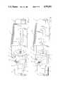
- FIG. 1is a side elevation of a first embodiment of a steering column incorporating the present invention
- FIG. 2is a plan view of the steering column illustrated in FIG. 1;
- FIG. 3is an enlarged, fragmentary side elevation, illustrating the locking pawls in their locked position
- FIG. 4is an enlarged, fragmentary view, similar to FIG. 3, but illustrating the telescope locking pawl in its released position, in which telescoping movement of the column is permitted;
- FIG. 5is an enlarged, fragmentary section similar to FIGS. 3 and 4, with the telescope locking structure removed so as to illustrate the tilt lock structure in its locked position;
- FIG. 6is an enlarged, fragmentary, section similar to FIG. 5, illustrating the tilt lock pawl in its released position, in which tilt adjustment of the steering column is permitted;
- FIG. 7is an enlarged, fragmentary plan view illustrating the mounting of the control lever
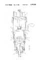
- FIG. 8is a schematic, longitudinal section of the steering column, with parts removed for purposes of clarity and illustrating the internal components of the steering column;
- FIG. 9is a cross section, taken along line 9--9 of FIG. 8;
- FIG. 10is a plan view, partially in section, of a second embodiment of this invention.
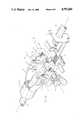
- FIG. 11is a schematic, perspective view illustrating the general arrangement of the lock mechanism of the second embodiment
- FIG. 12is a fragmentary side elevation illustrating the tilt lock mechanism
- FIG. 13is a fragmentary side elevation, with parts removed, illustrating the tilt lock mechanism.
- FIGS. 1 through 9illustrate a first embodiment of this invention, which includes three housing assemblies interconnected to provide both tilting adjustment of the column and longitudinal telescoping adjustment of the column.
- a first housing assembly 10is mounted on the vehicle and is pivotally connected to a second housing assembly 11 by a pivot 12. This pivot permits pivotal movement of the second housing assembly 11 relative to the first housing assembly 10 through an angle A in both directions from the aligned position illustrated in the drawings.
- a third housing assembly 13is mounted on the second housing assembly 11 for longitudinal telescoping movement relative thereto between the retracted position illustrated in the drawings and a plurality of extended positions illustrated in phantom within the bracket 14.
- the third housing assemblycan be locked in any one of eleven positions of extension, as discussed in detail below.
- the second housing assembly 11, and in turn the third housing assembly 13can be locked in any one of seven tilt positions, with three tilt positions provided on each side of the straight positions.
- the manner in which the tilting lock functionsis described in detail below.
- FIG. 8schematically illustrates the internal structure of the steering column.
- the first housing assembly 10includes a tubular member 16 having a trunnion 17 mounted thereon by a weld 18.
- the trunnion 17provides opposed, longitudinally extending side portions 19.
- the second housing assembly 11also provides a tubular member 20 having a bracket 21 secured thereto by a weld 22.
- the bracket 21provides a pair of longitudinally extending, parallel sides 23 which extend along the inner sides of the associated side portions 19 of the trunnion 17 and are connected by the pivots 12 for relative rotation about a lateral tilt pivot axis 24.
- the tubular member 20 of the second housing assemblyextends into a tubular member 26 which is part of the third housing assembly 13.
- a relatively close fitis provided between the two tubular members 20 and 26 so that they are maintained in axial alignment but they are free to telescope axially relative to each other.
- a steering shaft system 31which is adapted at one end 32 to be connected to the vehicle steering linkage and is adapted at its other end 33 for the mounting of a steering wheel (not illustrated).
- the shaft system 31includes three shaft members 34, 36, and 37.
- the shaft member 34is journaled adjacent to its end 32 in a bearing 38 mounted at the end of the tubular member 16 and extends along the tubular member 16 into the trunnion 17.
- a universal joint 39having an operating axis coaxial with the pivot axis 24 connects the inner end of the shaft member 34 to the shaft member 36.
- the shaft member 36extends from the universal joint 39 along the tubular member 20, and is axially and laterally fixed therein by the bearings 41.
- the shaft member 36is provided with a non-circular, double D-shape, best illustrated in FIG. 9, and extends into the inner end 42 of the third shaft member 17.
- the inner end of the shaft member 37is also formed with a non-circular double D shape, best illustrated in FIG. 9, and closely fits the periphery of the shaft member 36. Therefore, the two shaft members 36 and 37 are locked against relative rotation, although they are free to move axially relative to each other with telescoping movement.
- a third bearing 43journals the shaft member 37 at the outer end of the tubular member 26 and prevents relative axial movement therebetween while permitting relative rotation therebetween.
- the tilt lock system(described in detail below) is released and the housing assembly 11, and in turn the housing assembly 13, along with the two shafts 36 and 37, are pivoted about the axis 24 to the desired adjusted position, and then locked in such adjusted position by the tilt lock mechanism. Because the universal joint 39 is aligned with the pivot axis 24, the operation of the shaft system is not affected by the tilt adjustment.
- a telescope lock mechanism(described in detail below) is released and the third housing assembly 13, along with the shaft member 37, is free for movement longitudinally to the desired adjusted position and is then locked by the telescope lock mechanism in the adjusted telescoped position.
- the telescope lock mechanism 46is best illustrated in FIGS. 3 and 4, and includes a telescope lock pawl 47 and a toothed rack 48.
- the toothed rack 48is welded to one side of the tubular member 26 at 49, and provides an offset 51, best illustrated in FIG. 7, from which a toothed rack portion 52 extends along the side of one of the side portions 19 of the trunnion 17.
- the toothed rack portion 52is provided with longitudinally spaced teeth 53 along its length. In the illustrated embodiment, there are eleven teeth 53, permitting the steering column to be locked in any one of eleven telescoped positions.
- the telescope lock pawl 47is mounted on the bracket 21 by a pivot screw 54 which extends through an arcuate slot 56 formed in the adjacent side portion 19 of the trunnion 17 and is threaded into the adjacent side 23 of the bracket 21.
- This pivotal mounting of the telescope pawl 47permits pivotal movement of the pawl about a pivot axis 57, which is spaced from the pivot axis 24, and, in the illustrated embodiment, is parallel thereto.
- the telescope lock pawl 47is provided with a tooth 58, sized and shaped to mate with any one of the teeth 53 on the rack 48, and, when the pawl is in the locked position of FIG. 3, prevents relative axial telescoping movement between the second housing 11 and the third housing 13. However, when the pawl 47 is pivoted clockwise from the position of FIG. 3 to the position of FIG. 4, the tooth 58 is lifted clear of the rack 48 and the column is free to be telescoped in or out to any desired adjusted position. After adjustment, the pawl 47 returns to the locked position and maintains the column in the adjusted position.
- Movement of the telescope lock pawl 47 from its locked position of FIG. 3 to its released position of FIG. 4is provided by a control lever 59, as discussed below, and a spring 61 which engages the pawl 47 at one end functions to return the pawl to its locked position after telescoping adjustment is completed.
- the toothed rack 48is provided with a lateral projection 62 which engages the pawl 47 adjacent to the pivot member 54 to limit extension of the steering column. Inward telescoping movmement is limited by engagement between the inner end of the tubular member 26 and the bracket 21. The rack 48 also prevents rotation of the third housing assembly 13 relative to the second housing assembly 11.
- a tilt lock mechanism 63is best illustrated in FIGS. 5 and 6, and includes a tilt lock pawl 64.
- the pawl 64is pivotally mounted on the bracket 21 by a pivot screw 66 for limited pivotal movement about a pivot axis 67.
- the end of the adjacent side portion 19 of the trunnionis provided with a toothed sector 68 having a plurality of teeth 69 equally spaced from the tilt pivot axis 24 and radially positioned with respect to such axis.
- the teeth 69provide seven tilt positions in which the tilt lock mechanism 63 can lock the column.
- the tilt lock pawl 64is provided with a tooth 71 sized to interfit and mate with the teeth 69 when the pawl is in the tilt lock position of FIG. 5 and which is moved clear of the tooth sector 68 when it is pivoted in an anticlockwise direction to the position of FIG. 6.
- the movement of the tilt lock pawl between the locked position of FIG. 5 and the release position of FIG. 6is provided by the control lever 59, as discussed below.
- the spring 61which extends between the pawl 64 and the pawl 47, operates to return the tilt lock pawl to its locked position of FIG. 5 when the control lever 59 is released.
- the pivot fastener 54which extends through the arcuate slot 56, functions to limit the amount of tilt movement in both directions from the neutral position illustrated.
- the control lever 59is pivoted on the bracket 21 by a pivot pin 72, as illustrated in FIG. 7, and extends laterally between the two pawls 47 and 64.
- a pivot pin 72When the control lever 59 is pivoted in a clockwise direction from its neutral position illustrated in FIG. 7 to the phantom position 59a, it engages the tilt lock pawl and moves it to the release position. Such movement, however, has no effect on the telescope lock pawl 47, and therefore the column remains locked against telescoping movement during tilt adjustment.
- control leverwhen the control lever is rotated about the pivot 72 in the opposite direction to the phantom line position 59b, it engages the telescope lock pawl 47 and moves such pawl to its release position, allowing telescope adjustment of the column. In such position 59b, however, the tilt lock pawl 64 remains in the locked position, so the column is locked against tilting adjustment while telescope adjustment is taking place.
- a compression spring 73 positioned within the tubular shaft member 37engages the end of the shaft member 36 and provides a resilient force urging the column toward the maximum extended position so that the column moves to such extended position without effort on the part of the operator when the telescope lock pawl is released.
- the vehicle operatormerely releases the telescope lock pawl by moving the control lever 59 to the position 59b and presses inwardly on the steering wheel until the desired telescope lock position is reached. Release of the control lever relocks the telescope lock pawl 47 and locks the column in the adjusted telescope position.
- a tension spring 74is connected between the trunnion 17 and the bracket 21, and resiliently urges the column toward the maximum up-tilt position.
- the vehicle operatormerely releases the tilt lock mechanism 63 and presses downwardly on the steering wheel until the desired tilt position is reached, after which the control lever 59 is released and the tilt lock mechanism re-engages to lock the column in the adjusted tilt position.
- the single spring 61serves three functions: it biases the telescope lock pawl 47 to its normal locked position; it biases the tilt lock pawl 64 toward its normal locked position; and it also normally maintains the control lever 59 in the neutral position in which both lock mechanisms remain locked.
- a light spring 76is preferably provided to apply a light clockwise bias to the control lever 59 to prevent rattle. However, such spring 76 is not sufficiently strong to overcome the action of the spring 61 in maintaining the tilt lock pawl in its locked position.
- FIGS. 10 through 13illustrate a second embodiment of a tilt and telescope steering column in accordance with this invention.
- the columnagain provides three housing assemblies 81, 82, and 83, which for purposes of illustration are schematically illustrated.
- the housing assembly 82includes an inner housing part interconnected to an outer housing part.
- the housing assembly 81is fixed to the vehicle to provide the support for the steering column.
- the housing assembly 82is pivotally mounted on the housing assembly 81 by a pivot 80 including a male pivot part mounted on the housing 82 and an opening in the housing 81 for pivotal movement about a pivot axis 84. Such pivot permits the tilting of the housing assembly 82 with respect to the housing assembly 81.
- the housing 81is formed with arcuate slots 81a through which a pin 82a on the housing 82 extends to limit the pivotal movement between the two housings 81 and 82.
- the housing assembly 83is longitudinally movable relative to the housing assembly 82 to provide the telescoping adjustment of the steering column.
- the shaft systemagain provides two shafts 86 and 87 connected by a universal joint 88 having an operating axis coaxial with the pivot axis 84.
- the shaft 86is journaled in a bearing 86a in the housing 81.
- a third shaft 89telescopes into the shaft 87 and is axially movable relative to the shaft 87 during the telescoping adjustment.
- a non-circular configurationis provided in both of the shafts 87 and 89, as illustrated in FIG. 9 of the first embodiment, so that they are fixed against relative rotation but are axially movable relative to each other.
- a control lever assembly 91includes a shaft 92 journaled on the housing assembly 82 for oscillating rotation about a pivot axis 93 which is spaced from and parallel to the main pivot axis 84.
- the tilt lockincludes a pair of laterally spaced pawls 96 which are mounted on the shaft 92 on opposite sides of the steering column.
- Each of the pawls 96is provided with teeth 98 which interfit with teeth 99 formed in the end of the first housing 81 to prevent tilting movement of the second housing assembly 82 about the pivot axis 84 when the pawls 96 and 97 are in the locked position illustrated in FIG. 11.
- the telescoping lock systemincludes a toothed rack 101 which is provided with a lateral portion 102 mounted on the third housing assembly 83 by fasteners 100 illustrated in FIGS. 12 and 13.
- the lateral portion 102is also connected to the third shaft 89 and locked against relative axial movement while permitting relative rotation therebetween.
- a telescope lock pawl 103is also mounted on the shaft 92 for limited pivotal movement relative thereto, and is provided with a tooth 104 which interfits with the teeth formed in the rack 101 to lock the rack against axial movement when in the locked position illustrated in FIG. 11.
- a strap 106 mounted on the second housing assembly 82supports the side of the rack 101 opposite the pawl 103 and prevents lateral movement of the rack away from the pawl while permitting axial movement of the rack with respect to the pawl during the telescoping adjustment of the column.
- the rack 101prevents relative rotation between the two housing assemblies 82 and 83.
- the locking and release movement of the pawl 96is best illustrated in FIG. 12, in which the pawl 96 is illustrated in its locked position in which its teeth 98 engage the teeth 99.
- a spring 107 associated with the pawl 96normally maintains the associated pawl in its locked position.
- a cross-pin 108is mounted on the shaft 92 and extends beyond the periphery thereof at both ends into associated slots 109 formed in the associated pawl 96.
- the slotsare sized and positioned with respect to the pin so that when the control lever 91 is in its neutral position 91a, as illustrated in FIG. 12, the spring 107 maintains the two pawls in their locked position. However, when the control lever is moved in a clockwise direction, as illustrated in FIG.
- the pins 108 associated with the pawlsengage the end of the associated slots 109 and cause the two pawls to rotate in a clockwise direction, lifting the teeth 98 of the pawls away from the teeth 99 on the first housing assembly 81 so that the column is released for tilting adjustment.
- the control leveris released, and the springs 107 return the two pawls to the locked condition and lock the column in the desired adjusted tilt position.
- a similar structureis provided for causing the control lever 91 to release the telescope lock pawl 103.
- the telescope lock pawlis normally maintained in the locked position illustrated in FIG. 13 by a spring 110.
- a pin 111is mounted in the shaft 92 and extends into an opening 112 formed in the pawl 103. This opening 112 is sized and positioned with respect to the pin 111 so that clockwise rotation of the shaft 92 to release the tilt lock pawls 96 and 97 does not cause movement of the telescope lock pawl 103.
- anticlockwise rotation from the control lever position 91aillustrated in phantom in FIG.
- the springs 107 and 110which normally maintain the associated pawls in their locked position operate to normally maintain the control lever 91 in its neutral position. Further, when the column is released for tilting adjustment, the telescoping lock mechanism remains locked. Conversely, when the telescoping lock system is released for telescoping adjustment, the tilt lock remains locked.
Landscapes
- Engineering & Computer Science (AREA)
- Chemical & Material Sciences (AREA)
- Combustion & Propulsion (AREA)
- Transportation (AREA)
- Mechanical Engineering (AREA)
- Steering Controls (AREA)
Abstract
Description
Claims (15)
Priority Applications (1)
| Application Number | Priority Date | Filing Date | Title |
|---|---|---|---|
| US07/125,565US4793204A (en) | 1987-11-25 | 1987-11-25 | Tilt and telescope steering column having a single control |
Applications Claiming Priority (1)
| Application Number | Priority Date | Filing Date | Title |
|---|---|---|---|
| US07/125,565US4793204A (en) | 1987-11-25 | 1987-11-25 | Tilt and telescope steering column having a single control |
Publications (1)
| Publication Number | Publication Date |
|---|---|
| US4793204Atrue US4793204A (en) | 1988-12-27 |
Family
ID=22420327
Family Applications (1)
| Application Number | Title | Priority Date | Filing Date |
|---|---|---|---|
| US07/125,565Expired - Fee RelatedUS4793204A (en) | 1987-11-25 | 1987-11-25 | Tilt and telescope steering column having a single control |
Country Status (1)
| Country | Link |
|---|---|
| US (1) | US4793204A (en) |
Cited By (57)
| Publication number | Priority date | Publication date | Assignee | Title |
|---|---|---|---|---|
| US5029489A (en)* | 1989-05-03 | 1991-07-09 | Lemforder Metallwaren Ag | Steering column with vertically adjustable steering wheel for motor vehicles |
| WO1992004222A1 (en)* | 1990-08-31 | 1992-03-19 | Imo Industries, Inc. | Tiltable marine steering helm |
| US5161425A (en)* | 1990-01-27 | 1992-11-10 | Ford Motor Company | Adjustable steering column mechanism |
| US5168769A (en)* | 1991-05-24 | 1992-12-08 | The United States Of America As Represented By The Secretary Of The Army | Dual acting brake actuator |
| US5168768A (en)* | 1992-01-14 | 1992-12-08 | Deere & Company | Tilt steering column assembly |
| US5339706A (en)* | 1993-03-26 | 1994-08-23 | Chrysler Corporation | Latchable steering column tilt mechanism |
| EP0641705A1 (en)* | 1993-09-01 | 1995-03-08 | The Torrington Company Limited | Adjustable steering column assembly for a vehicle |
| EP0749087A2 (en) | 1995-05-01 | 1996-12-18 | UNITED TECHNOLOGIES AUTOMOTIVE, Inc. | Electrical switch for use in an automotive vehicle |
| US5711189A (en)* | 1996-05-20 | 1998-01-27 | Trw Inc. | Steering column |
| US5813289A (en)* | 1996-05-14 | 1998-09-29 | Trw Inc. | Steering column |
| US5813699A (en)* | 1994-10-10 | 1998-09-29 | Leopold Kostal Gmbh & Co. Kg | Steering device for motor vehicles |
| US5829311A (en)* | 1996-08-15 | 1998-11-03 | Roberson; Jarried E. | Motorized tilt steering device |
| US5899497A (en)* | 1997-09-24 | 1999-05-04 | Douglas Autotech Corp. | Tilt-adjustable steering column assembly |
| US20040012184A1 (en)* | 2000-06-02 | 2004-01-22 | Hege Reitan | Device for allowing adjustment of the position of a steering member in a vehicle |
| US6695349B2 (en)* | 2000-08-16 | 2004-02-24 | Daimlerchrysler Ag | Positional adjustment apparatus for a steering column |
| US20050145056A1 (en)* | 2003-12-08 | 2005-07-07 | Maida Robert D. | Tilt control lever assembly for steering column |
| US20050199087A1 (en)* | 2004-03-11 | 2005-09-15 | Xiaoyu Li | Single-motor power telescope and tilt steering column |
| US20060076763A1 (en)* | 2004-10-07 | 2006-04-13 | Delphi Technologies, Inc. | Rake and telescope column lock safety function |
| US20060082119A1 (en)* | 2004-10-14 | 2006-04-20 | Tinnin Melvin L | Lock for tilting and telescoping steering column |
| US20060266152A1 (en)* | 2005-05-26 | 2006-11-30 | Armstrong Ray G | One lever tilt and telescope mechanism |
| US20080060467A1 (en)* | 2006-09-13 | 2008-03-13 | Manwaring Marvin V | Central lock device of an adjustable steering column assembly |
| US20080141815A1 (en)* | 2006-10-12 | 2008-06-19 | Ridgway Jason R | Steering column assembly for a vehicle |
| US20080150269A1 (en)* | 2006-11-14 | 2008-06-26 | Biagio Longo | Steering column |
| US20080191456A1 (en)* | 2007-02-09 | 2008-08-14 | Ridgway Jason R | Steering column assembly |
| US20080191457A1 (en)* | 2007-02-09 | 2008-08-14 | Ridgway Jason R | Adjustable steering column assembly for a vehicle |
| US20080229865A1 (en)* | 2007-03-21 | 2008-09-25 | Manwaring Marvin V | Central lock device of an adjustable steering column assembly |
| US20080231031A1 (en)* | 2007-03-21 | 2008-09-25 | Manwaring Marvin V | Releasable push/pull lock device of an adjustable steering column assembly |
| US20080238068A1 (en)* | 2007-03-30 | 2008-10-02 | Nissan Technical Center North America, Inc. | Vehicle steering column structure |
| US20080236325A1 (en)* | 2007-03-30 | 2008-10-02 | Delphi Technologies, Inc. | Lock mechanism for an adjustable steering column assembly |
| US20080238069A1 (en)* | 2007-03-30 | 2008-10-02 | Nissan Technical Center North America, Inc. | Vehicle steering column structure |
| US20080245176A1 (en)* | 2007-04-04 | 2008-10-09 | Manwaring Marvin V | Steering column assembly having an actuation mechanism for telescoping and tilting movement |
| WO2009121386A1 (en)* | 2008-03-31 | 2009-10-08 | Thyssenkrupp Presta Aktiengesellschaft | Steering column for a motor vehicle |
| US20090250916A1 (en)* | 2008-04-07 | 2009-10-08 | Delphi Technologies, Inc. | Adjustable steering column assembly for a vehicle |
| US20090266195A1 (en)* | 2008-04-23 | 2009-10-29 | Delphi Technologies, Inc. | Adjustable steering column assembly |
| US7635149B2 (en) | 2007-03-21 | 2009-12-22 | Gm Global Technology Operations, Inc. | Rocker-arm lock device of an adjustable steering column assembly |
| US20110163206A1 (en)* | 2009-12-30 | 2011-07-07 | Agusta S.P.A. | Helicopter control stick support assembly |
| ITMI20100655A1 (en)* | 2010-04-16 | 2011-10-17 | A M A S P A | STEERING COLUMN |
| US20120125140A1 (en)* | 2010-11-23 | 2012-05-24 | Gm Global Technology Operations, Inc. | Telescope positive lock for steering column |
| US20120125139A1 (en)* | 2010-11-23 | 2012-05-24 | Gm Global Technology Operations, Inc. | Steering column telescope lock |
| US20120234985A1 (en)* | 2011-03-18 | 2012-09-20 | Eurocopter | Cyclic stick for mechanically transmitting commands for controlling a rotorcraft, the stick having a lever arm that is amplified selectively in the event of an emergency |
| EP2121412A4 (en)* | 2007-02-22 | 2012-12-05 | Scania Cv Abp | Steering column for a vehicle |
| US20130205935A1 (en)* | 2012-02-15 | 2013-08-15 | Steering Solutions Ip Holding Corporation | Steering column telescope and e/a locking device |
| US20130298717A1 (en)* | 2012-05-10 | 2013-11-14 | Steering Solutions Ip Holding Corporation | Locking Device for Steering Column |
| US20140070050A1 (en)* | 2007-08-09 | 2014-03-13 | Lta Corporation | Lenticular airship and associated controls |
| US20140076092A1 (en)* | 2012-09-18 | 2014-03-20 | Mando Corporation | Steering column for vehicle |
| US8827311B2 (en) | 2010-05-25 | 2014-09-09 | Thyssenkrupp Presta Aktiengesellschaft | Spring element |
| US8894097B2 (en) | 2010-06-28 | 2014-11-25 | Thyssenkrupp Presta Aktiengesellschaft | Adjustable steering column for a motor vehicle |
| US8967724B2 (en) | 2012-09-20 | 2015-03-03 | Steelcase Inc. | Chair arm assembly |
| US9233707B2 (en) | 2010-12-15 | 2016-01-12 | Thyssenkrupp Presta Aktiengesellschaft | Steering column for a motor vehicle |
| US20160075367A1 (en)* | 2014-09-17 | 2016-03-17 | Jtekt Corporation | Steering device |
| EP3178723A1 (en)* | 2015-12-10 | 2017-06-14 | A.M.A. S.p.A. | Steering column for vehicles |
| CN108290597A (en)* | 2015-11-06 | 2018-07-17 | Mmx-麦肯诺普拉斯特有限责任公司 | Steering column |
| US10113573B2 (en)* | 2015-11-05 | 2018-10-30 | Raytheon Company | Sequencing locking mechanism for telescoging structures |
| US10654513B2 (en) | 2016-03-23 | 2020-05-19 | Trw Automotive Gmbh | Steering column assembly |
| WO2020251490A1 (en)* | 2019-06-14 | 2020-12-17 | İleri̇ Mekani̇k Maki̇na Kalip İmalat Sanayi̇ Ve Ti̇caret Anoni̇m Şi̇rketi̇ | Interlock system by means of single-lever gear mechanism in steering columns capable of tilt telescopic adjustment |
| US11304528B2 (en) | 2012-09-20 | 2022-04-19 | Steelcase Inc. | Chair assembly with upholstery covering |
| US11370472B2 (en)* | 2019-12-12 | 2022-06-28 | Mahindra N.A. Tech Center | Steering column tilt lock |
Citations (1)
| Publication number | Priority date | Publication date | Assignee | Title |
|---|---|---|---|---|
| US3285090A (en)* | 1965-05-20 | 1966-11-15 | Gen Motors Corp | Adjustable steering column |
- 1987
- 1987-11-25USUS07/125,565patent/US4793204A/ennot_activeExpired - Fee Related
Patent Citations (1)
| Publication number | Priority date | Publication date | Assignee | Title |
|---|---|---|---|---|
| US3285090A (en)* | 1965-05-20 | 1966-11-15 | Gen Motors Corp | Adjustable steering column |
Cited By (101)
| Publication number | Priority date | Publication date | Assignee | Title |
|---|---|---|---|---|
| US5029489A (en)* | 1989-05-03 | 1991-07-09 | Lemforder Metallwaren Ag | Steering column with vertically adjustable steering wheel for motor vehicles |
| US5161425A (en)* | 1990-01-27 | 1992-11-10 | Ford Motor Company | Adjustable steering column mechanism |
| WO1992004222A1 (en)* | 1990-08-31 | 1992-03-19 | Imo Industries, Inc. | Tiltable marine steering helm |
| US5136894A (en)* | 1990-08-31 | 1992-08-11 | Imo Industries, Inc. | Tiltable marine steering helm |
| US5168769A (en)* | 1991-05-24 | 1992-12-08 | The United States Of America As Represented By The Secretary Of The Army | Dual acting brake actuator |
| US5168768A (en)* | 1992-01-14 | 1992-12-08 | Deere & Company | Tilt steering column assembly |
| US5339706A (en)* | 1993-03-26 | 1994-08-23 | Chrysler Corporation | Latchable steering column tilt mechanism |
| US5524927A (en)* | 1993-09-01 | 1996-06-11 | The Torrington Company | Adjustable steering column assembly for a vehicle |
| EP0641705A1 (en)* | 1993-09-01 | 1995-03-08 | The Torrington Company Limited | Adjustable steering column assembly for a vehicle |
| US5744769A (en)* | 1993-09-13 | 1998-04-28 | United Technologies Automotive, Inc. | Electrical switch for use in an automotive vehicle |
| US5813699A (en)* | 1994-10-10 | 1998-09-29 | Leopold Kostal Gmbh & Co. Kg | Steering device for motor vehicles |
| EP0749087A2 (en) | 1995-05-01 | 1996-12-18 | UNITED TECHNOLOGIES AUTOMOTIVE, Inc. | Electrical switch for use in an automotive vehicle |
| US5813289A (en)* | 1996-05-14 | 1998-09-29 | Trw Inc. | Steering column |
| AU698974B2 (en)* | 1996-05-14 | 1998-11-12 | Trw Inc. | Steering column |
| US5711189A (en)* | 1996-05-20 | 1998-01-27 | Trw Inc. | Steering column |
| AU696464B2 (en)* | 1996-05-20 | 1998-09-10 | Trw Inc. | Steering column |
| US5829311A (en)* | 1996-08-15 | 1998-11-03 | Roberson; Jarried E. | Motorized tilt steering device |
| US5899497A (en)* | 1997-09-24 | 1999-05-04 | Douglas Autotech Corp. | Tilt-adjustable steering column assembly |
| US20040012184A1 (en)* | 2000-06-02 | 2004-01-22 | Hege Reitan | Device for allowing adjustment of the position of a steering member in a vehicle |
| US6966580B2 (en)* | 2000-06-02 | 2005-11-22 | Scania Cv Ab (Publ) | Device for allowing adjustment of the position of a steering member in a vehicle |
| US6695349B2 (en)* | 2000-08-16 | 2004-02-24 | Daimlerchrysler Ag | Positional adjustment apparatus for a steering column |
| US7263910B2 (en)* | 2003-12-08 | 2007-09-04 | Delphi Technologies, Inc. | Tilt control lever assembly for steering column |
| US20050145056A1 (en)* | 2003-12-08 | 2005-07-07 | Maida Robert D. | Tilt control lever assembly for steering column |
| US20050199087A1 (en)* | 2004-03-11 | 2005-09-15 | Xiaoyu Li | Single-motor power telescope and tilt steering column |
| US7293481B2 (en)* | 2004-03-11 | 2007-11-13 | Delphi Technologies, Inc. | Single-motor power telescope and tilt steering column |
| US7278660B2 (en) | 2004-10-07 | 2007-10-09 | Delphi Technologies, Inc. | Rake and telescope column lock safety function |
| US20060076763A1 (en)* | 2004-10-07 | 2006-04-13 | Delphi Technologies, Inc. | Rake and telescope column lock safety function |
| US20060082119A1 (en)* | 2004-10-14 | 2006-04-20 | Tinnin Melvin L | Lock for tilting and telescoping steering column |
| US7306259B2 (en)* | 2004-10-14 | 2007-12-11 | Delphi Technologies, Inc. | Lock for tilting and telescoping steering column |
| US20060266152A1 (en)* | 2005-05-26 | 2006-11-30 | Armstrong Ray G | One lever tilt and telescope mechanism |
| US7503234B2 (en)* | 2005-05-26 | 2009-03-17 | Delphi Technologies, Inc. | One lever tilt and telescope mechanism |
| US20080060467A1 (en)* | 2006-09-13 | 2008-03-13 | Manwaring Marvin V | Central lock device of an adjustable steering column assembly |
| US7640824B2 (en) | 2006-09-13 | 2010-01-05 | Gm Global Technology Operations, Inc. | Central lock device of an adjustable steering column assembly |
| US20080141815A1 (en)* | 2006-10-12 | 2008-06-19 | Ridgway Jason R | Steering column assembly for a vehicle |
| US20080150269A1 (en)* | 2006-11-14 | 2008-06-26 | Biagio Longo | Steering column |
| US7621562B2 (en)* | 2006-11-14 | 2009-11-24 | A.M.A. S.P.A. | Steering column |
| US7735868B2 (en)* | 2007-02-09 | 2010-06-15 | Gm Global Technology Operations, Inc. | Adjustable steering column assembly for a vehicle |
| US7587959B2 (en) | 2007-02-09 | 2009-09-15 | Delphi Technologies, Inc. | Steering column assembly |
| US20080191456A1 (en)* | 2007-02-09 | 2008-08-14 | Ridgway Jason R | Steering column assembly |
| US20080191457A1 (en)* | 2007-02-09 | 2008-08-14 | Ridgway Jason R | Adjustable steering column assembly for a vehicle |
| EP2121412A4 (en)* | 2007-02-22 | 2012-12-05 | Scania Cv Abp | Steering column for a vehicle |
| US7730804B2 (en)* | 2007-03-21 | 2010-06-08 | Gm Global Technology Operations, Inc. | Central lock device of an adjustable steering column assembly |
| US7621197B2 (en) | 2007-03-21 | 2009-11-24 | Gm Global Technology Operations, Inc. | Releasable push/pull lock device of an adjustable steering column assembly |
| US7635149B2 (en) | 2007-03-21 | 2009-12-22 | Gm Global Technology Operations, Inc. | Rocker-arm lock device of an adjustable steering column assembly |
| US20080231031A1 (en)* | 2007-03-21 | 2008-09-25 | Manwaring Marvin V | Releasable push/pull lock device of an adjustable steering column assembly |
| US20080229865A1 (en)* | 2007-03-21 | 2008-09-25 | Manwaring Marvin V | Central lock device of an adjustable steering column assembly |
| US8047096B2 (en)* | 2007-03-30 | 2011-11-01 | Nexteer (Beijing) Technology Co., Ltd. | Lock mechanism for an adjustable steering column assembly |
| US20080236325A1 (en)* | 2007-03-30 | 2008-10-02 | Delphi Technologies, Inc. | Lock mechanism for an adjustable steering column assembly |
| US20080238069A1 (en)* | 2007-03-30 | 2008-10-02 | Nissan Technical Center North America, Inc. | Vehicle steering column structure |
| US20080238068A1 (en)* | 2007-03-30 | 2008-10-02 | Nissan Technical Center North America, Inc. | Vehicle steering column structure |
| US7770487B2 (en) | 2007-03-30 | 2010-08-10 | Nissan Technical Center North America, Inc. | Vehicle steering column structure |
| US7823479B2 (en) | 2007-03-30 | 2010-11-02 | Nissan Technical Center North America, Inc. | Vehicle steering column structure |
| US20080245176A1 (en)* | 2007-04-04 | 2008-10-09 | Manwaring Marvin V | Steering column assembly having an actuation mechanism for telescoping and tilting movement |
| US7743681B2 (en)* | 2007-04-04 | 2010-06-29 | Gm Global Technology Operations, Inc. | Steering column assembly having an actuation mechanism for telescoping and tilting movement |
| US20140070050A1 (en)* | 2007-08-09 | 2014-03-13 | Lta Corporation | Lenticular airship and associated controls |
| US9840318B2 (en)* | 2007-08-09 | 2017-12-12 | Pierre Balaskovic | Lenticular airship and associated controls |
| RU2488507C2 (en)* | 2008-03-31 | 2013-07-27 | Тиссенкрупп Преста Акциенгезельшафт | Automotive steering column |
| US9610969B2 (en) | 2008-03-31 | 2017-04-04 | Thyssenkrupp Presta Aktiengesellschaft | Steering column for a motor vehicle |
| CN102015414B (en)* | 2008-03-31 | 2015-07-29 | 蒂森克鲁伯普雷斯塔公司 | car steering column |
| WO2009121386A1 (en)* | 2008-03-31 | 2009-10-08 | Thyssenkrupp Presta Aktiengesellschaft | Steering column for a motor vehicle |
| US9399481B2 (en) | 2008-03-31 | 2016-07-26 | Thyssenkrupp Presta Aktiengesellschaft | Steering column for a motor vehicle |
| US20100282016A1 (en)* | 2008-03-31 | 2010-11-11 | Oehri Martin | Steering column for a motor vehicle |
| US7914043B2 (en) | 2008-04-07 | 2011-03-29 | Nexteer (Beijing) Technology Co., Ltd. | Adjustable steering column assembly for a vehicle |
| US20090250916A1 (en)* | 2008-04-07 | 2009-10-08 | Delphi Technologies, Inc. | Adjustable steering column assembly for a vehicle |
| US20090266195A1 (en)* | 2008-04-23 | 2009-10-29 | Delphi Technologies, Inc. | Adjustable steering column assembly |
| US8359945B2 (en)* | 2008-04-23 | 2013-01-29 | Steering Solutions Ip Holding Corporation | Adjustable steering column assembly |
| US8991770B2 (en) | 2009-12-30 | 2015-03-31 | Agusta S.P.A. | Helicopter control stick support assembly |
| US20110163206A1 (en)* | 2009-12-30 | 2011-07-07 | Agusta S.P.A. | Helicopter control stick support assembly |
| US8556216B2 (en)* | 2009-12-30 | 2013-10-15 | Agusta S.P.A. | Helicopter control stick support assembly |
| EP2377741A1 (en)* | 2010-04-16 | 2011-10-19 | A.M.A. S.p.A. | Steering column |
| ITMI20100655A1 (en)* | 2010-04-16 | 2011-10-17 | A M A S P A | STEERING COLUMN |
| US8827311B2 (en) | 2010-05-25 | 2014-09-09 | Thyssenkrupp Presta Aktiengesellschaft | Spring element |
| US8894097B2 (en) | 2010-06-28 | 2014-11-25 | Thyssenkrupp Presta Aktiengesellschaft | Adjustable steering column for a motor vehicle |
| US8438944B2 (en)* | 2010-11-23 | 2013-05-14 | Steering Solutions Ip Holding Corporation | Telescope positive lock for steering column |
| US20120125139A1 (en)* | 2010-11-23 | 2012-05-24 | Gm Global Technology Operations, Inc. | Steering column telescope lock |
| US20120125140A1 (en)* | 2010-11-23 | 2012-05-24 | Gm Global Technology Operations, Inc. | Telescope positive lock for steering column |
| US8783717B2 (en)* | 2010-11-23 | 2014-07-22 | Steering Solutions Ip Holding Corporation | Steering column telescope lock |
| US9233707B2 (en) | 2010-12-15 | 2016-01-12 | Thyssenkrupp Presta Aktiengesellschaft | Steering column for a motor vehicle |
| US20120234985A1 (en)* | 2011-03-18 | 2012-09-20 | Eurocopter | Cyclic stick for mechanically transmitting commands for controlling a rotorcraft, the stick having a lever arm that is amplified selectively in the event of an emergency |
| US8590843B2 (en)* | 2011-03-18 | 2013-11-26 | Eurocopter | Cyclic stick for mechanically transmitting commands for controlling a rotorcraft, the stick having a lever arm that is amplified selectively in the event of an emergency |
| US8978510B2 (en)* | 2012-02-15 | 2015-03-17 | Steering Solutions Ip Holding Corporation | Steering column telescope and E/A locking device |
| US20130205935A1 (en)* | 2012-02-15 | 2013-08-15 | Steering Solutions Ip Holding Corporation | Steering column telescope and e/a locking device |
| US20130298717A1 (en)* | 2012-05-10 | 2013-11-14 | Steering Solutions Ip Holding Corporation | Locking Device for Steering Column |
| US8936274B2 (en)* | 2012-05-10 | 2015-01-20 | Steering Solutions Ip Holding Corporation | Locking device for steering column |
| US20140076092A1 (en)* | 2012-09-18 | 2014-03-20 | Mando Corporation | Steering column for vehicle |
| US9156490B2 (en)* | 2012-09-18 | 2015-10-13 | Mando Corporation | Steering column for vehicle |
| US9028001B2 (en) | 2012-09-20 | 2015-05-12 | Steelcase Inc. | Chair arm assembly |
| US9427085B2 (en) | 2012-09-20 | 2016-08-30 | Steelcase Inc. | Chair arm assembly |
| US8967724B2 (en) | 2012-09-20 | 2015-03-03 | Steelcase Inc. | Chair arm assembly |
| US11304528B2 (en) | 2012-09-20 | 2022-04-19 | Steelcase Inc. | Chair assembly with upholstery covering |
| US10835041B2 (en) | 2012-09-20 | 2020-11-17 | Steelcase Inc. | Chair arm assembly |
| US10213019B2 (en) | 2012-09-20 | 2019-02-26 | Steelcase Inc. | Chair arm assembly |
| US9872565B2 (en) | 2012-09-20 | 2018-01-23 | Steelcase Inc. | Chair arm assembly |
| US9545943B2 (en)* | 2014-09-17 | 2017-01-17 | Jtekt Corporation | Steering device |
| US20160075367A1 (en)* | 2014-09-17 | 2016-03-17 | Jtekt Corporation | Steering device |
| US10113573B2 (en)* | 2015-11-05 | 2018-10-30 | Raytheon Company | Sequencing locking mechanism for telescoging structures |
| CN108290597A (en)* | 2015-11-06 | 2018-07-17 | Mmx-麦肯诺普拉斯特有限责任公司 | Steering column |
| EP3178723A1 (en)* | 2015-12-10 | 2017-06-14 | A.M.A. S.p.A. | Steering column for vehicles |
| US10654513B2 (en) | 2016-03-23 | 2020-05-19 | Trw Automotive Gmbh | Steering column assembly |
| WO2020251490A1 (en)* | 2019-06-14 | 2020-12-17 | İleri̇ Mekani̇k Maki̇na Kalip İmalat Sanayi̇ Ve Ti̇caret Anoni̇m Şi̇rketi̇ | Interlock system by means of single-lever gear mechanism in steering columns capable of tilt telescopic adjustment |
| US11370472B2 (en)* | 2019-12-12 | 2022-06-28 | Mahindra N.A. Tech Center | Steering column tilt lock |
Similar Documents
| Publication | Publication Date | Title |
|---|---|---|
| US4793204A (en) | Tilt and telescope steering column having a single control | |
| US6460427B1 (en) | Adjustment linkage for tilting and telescoping a steering column assembly | |
| US4102218A (en) | Fastening device for tiltable steering mechanisms | |
| JPS6130535Y2 (en) | ||
| EP0231453B1 (en) | Tilt-telescope steering column | |
| US7815220B2 (en) | Tilting and telescoping steering column assembly | |
| US6402168B1 (en) | Steering device for vehicle | |
| JPH0616171U (en) | Tilt type steering device | |
| US3693997A (en) | Adjustable steering column for motor vehicles | |
| KR100530030B1 (en) | Tilt steering apparatus for vehicle | |
| US7587959B2 (en) | Steering column assembly | |
| US4722241A (en) | Tiltable steering column with play provided between two tilt mechanism pawl release means | |
| EP2125487B1 (en) | Vehicle steering column | |
| US6279951B1 (en) | Steering column | |
| JPH0292779A (en) | Tilt and telescopic steering column | |
| JPH06234336A (en) | Device for adjusting height of seat particularly of car seat | |
| US7421925B2 (en) | Steering column tilt adjusting system | |
| JPH0143349Y2 (en) | ||
| JP3158865B2 (en) | Tilt steering system | |
| JP4648810B2 (en) | Electric tilt telescopic steering column | |
| GB2070919A (en) | A height-adjustable seat | |
| JP2611294B2 (en) | Steering device | |
| JP3555218B2 (en) | Seat reclining device | |
| JP3088448B2 (en) | Position adjustment device for vehicle seats, etc. | |
| JPH0712826B2 (en) | Tilt handle device for vehicle |
Legal Events
| Date | Code | Title | Description |
|---|---|---|---|
| FEPP | Fee payment procedure | Free format text:PAYOR NUMBER ASSIGNED (ORIGINAL EVENT CODE: ASPN); ENTITY STATUS OF PATENT OWNER: SMALL ENTITY | |
| AS | Assignment | Owner name:DOUGLAS COMPONENTS CORPORATION, A CORP. OF DE Free format text:ASSIGNMENT OF ASSIGNORS INTEREST.;ASSIGNOR:KUBASIAK, DUANE T.;REEL/FRAME:004788/0417 Effective date:19871112 Owner name:DOUGLAS COMPONENTS CORPORATION, A CORP. OF,DELAWAR Free format text:ASSIGNMENT OF ASSIGNORS INTEREST;ASSIGNOR:KUBASIAK, DUANE T.;REEL/FRAME:004788/0417 Effective date:19871112 | |
| CC | Certificate of correction | ||
| AS | Assignment | Owner name:DOUGLAS AUTOTECH CORPORATION, MICHIGAN Free format text:ASSIGNMENT OF ASSIGNORS INTEREST.;ASSIGNOR:DOUGLAS COMPONENTS CORPORATION, A CORP. OF DE;REEL/FRAME:005250/0301 Effective date:19891214 | |
| FPAY | Fee payment | Year of fee payment:4 | |
| REMI | Maintenance fee reminder mailed | ||
| LAPS | Lapse for failure to pay maintenance fees | ||
| FP | Lapsed due to failure to pay maintenance fee | Effective date:19970101 | |
| STCH | Information on status: patent discontinuation | Free format text:PATENT EXPIRED DUE TO NONPAYMENT OF MAINTENANCE FEES UNDER 37 CFR 1.362 |