US4792690A - Ultraviolet laser beam monitor using radiation responsive crystals - Google Patents
Ultraviolet laser beam monitor using radiation responsive crystalsDownload PDFInfo
- Publication number
- US4792690A US4792690AUS07/088,076US8807687AUS4792690AUS 4792690 AUS4792690 AUS 4792690AUS 8807687 AUS8807687 AUS 8807687AUS 4792690 AUS4792690 AUS 4792690A
- Authority
- US
- United States
- Prior art keywords
- crystal
- laser beam
- color pattern
- ultraviolet
- light
- Prior art date
- Legal status (The legal status is an assumption and is not a legal conclusion. Google has not performed a legal analysis and makes no representation as to the accuracy of the status listed.)
- Expired - Fee Related
Links
Images
Classifications
- G—PHYSICS
- G01—MEASURING; TESTING
- G01J—MEASUREMENT OF INTENSITY, VELOCITY, SPECTRAL CONTENT, POLARISATION, PHASE OR PULSE CHARACTERISTICS OF INFRARED, VISIBLE OR ULTRAVIOLET LIGHT; COLORIMETRY; RADIATION PYROMETRY
- G01J1/00—Photometry, e.g. photographic exposure meter
- G01J1/42—Photometry, e.g. photographic exposure meter using electric radiation detectors
- G01J1/4257—Photometry, e.g. photographic exposure meter using electric radiation detectors applied to monitoring the characteristics of a beam, e.g. laser beam, headlamp beam
- G—PHYSICS
- G01—MEASURING; TESTING
- G01J—MEASUREMENT OF INTENSITY, VELOCITY, SPECTRAL CONTENT, POLARISATION, PHASE OR PULSE CHARACTERISTICS OF INFRARED, VISIBLE OR ULTRAVIOLET LIGHT; COLORIMETRY; RADIATION PYROMETRY
- G01J1/00—Photometry, e.g. photographic exposure meter
- G01J1/58—Photometry, e.g. photographic exposure meter using luminescence generated by light
Definitions
- the present inventionrelates to an apparatus and method for monitoring the intensity distribution of an ultraviolet laser beam, and particularly relates to monitoring the intensity distribution of an ultraviolet laser beam in three-dimensions using a radiation sensitive crystal.
- Ultraviolet lasersare used in a wide variety of applications and experiments including laser surgery, laser welding, laser fusion, laser isotope separation, atomic and molecular physics research and laser spectroscopy. In practically all these applications, it is important have accurate beam profile measurements in order to achieve efficient and safe operation and meaningful experimental results.
- a laser beam profilecould be obtained by placing photodiodes in the beam to observe it, and reticon multi-channel plates are made for this purpose.
- the firstis cost.
- the photodiode platesare expensive and computers or other sophisticated electronics are required for data readout. Operation is difficult.
- the platesmust be carefully placed in the beam. Then, the plate must be moved parallel to the beam and multiple samples must be taken in order gather information as to the longitudinal beam profile.
- the placement and movement of the platesmust be done precisely and are sources of difficulty and error.
- the damage threshold of such devicesis generally low (about 0.1 mJ/cm 2 ) and the dynamic range is narrow compared to the present invention.
- this technique of monitoring a laser beaminvades and blocks the laser beam which may be undesirable in some applications.
- Another known technique for measuring or monitoring ultraviolet laser beamsuses photographic film placed in the path of the laser beam. Again this technique is difficult, requires precise positioning of the film and requires multiple samples of the laser beam at different positions to obtain longitudinal profile information of the beam.
- this crystalis an alkali halide crystal, such as potassium chloride doped with thallium, that will produce a color pattern when exposed to ultraviolet light.
- the crystalis disposed in the path of an ultraviolet laser beam for a selected period of time and a color pattern is formed within the crystal that corresponds to the intensity pattern of the laser beam as it passes through the crystal.
- the crystalhas a cubic or rectangular shape with polished planar faces on all sides so that the laser beam may enter and exit the crystal perpendicularly and the color pattern within the crystal may be observed substantially perpendicularly through the planar faces.
- the crystalis observed in a direction parallel to the path of the laser beam as it passed through the crystal and, to determine the longitudinal profile, the crystal is viewed along a direction substantially perpendicular to the laser beam path through the crystal.
- the second mentioned observationis essentially a side view of the laser beam longitudinal profile and it is most suited for determining laser beam divergence or convergence.
- a visible light optical systemsuch as a microscope
- a television camerawith or without a microscope
- the crystalmay be contained within a box having a shutter for admitting the laser beam in order to more precisely control the exposure of the crystal to the laser beam.
- the color pattern in the crystalis three-dimensional and this three-dimensional data was obtained without moving the crystal and without multiple sampling as required by prior art monitors discussed above. Also, the readout of the data may be obtained without the aid of a computer or other expensive electronic equipment. The crystal is simply observed with the naked eye. Thus, the present monitoring system is suitable for use by persons who are not skilled in the monitoring of lasers.
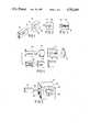
- FIG. 1is a perspective view of an ultraviolet laser illuminating an alkali halide crystal
- FIG. 2is a front view of the crystal in which the color pattern in the crystal is viewed in a direction parallel to the laser beam path through the crystal;
- FIG. 3is a side view of the crystal in which the color pattern is viewed in a direction perpendicular to the laser beam path throgh the crystal;
- FIG. 4is a diagrammatic view of an optics and video system that may be used to view the crystal after it has been exposed to the laser;
- FIG. 5is a diagrammatic view of a crystal mounted in a black box and exposed to a laser beam through a shutter;
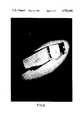
- FIG. 6is a photograph of a potassium chloride crystal in which a color pattern has been formed by an ultraviolet laser beam.
- FIG. 1an alkali halide crystal 10 being illuminated by an ultraviolet laser 12 that is producing a laser beam 14.
- the laser 12may be any of a number of ultraviolet or vacuum ultraviolet type lasers and it may be a frequency tripled (355 nanometers) and quadrupled (266 nanometers) ND:YAG laser.
- the preferred crystal 10is a potassium chloride crystal doped with thallium although other alkali halide crystals such as sodium chloride, potassium bromide and cesium bromide may be used. Also, it is preferred to use a cubic or rectangularly shaped crystal with polished parallel planar surfaces.
- the laser beam 14impinges upon the front surface 16 and creates a color pattern 18 within the crystal 10 that is also visible through the side surface 20 of the crystal 10. After the crystal 10 has been exposed to the ultraviolet laser beam 14, it may be viewed to determine the characteristics of the beam.
- FIG. 2there is a front view of the crystal 10 taken perpendicularly to the surface 16. In this view, the color pattern 18 reveals that the beam, in perpendicular cross-section, has an oval hole in its center and is somewhat donut shaped. Also, there are regions of increased intensity that appear as curved lines within the pattern 18.
- FIG. 3is a side view of the crystal 10 taken perpendicularly to the surface 20.
- the color pattern 18is converging and, thus, by simple observation it is possible to determine that the laser beam was converging as it went through the crystal.
- the degree of convergence in FIG. 3is exaggerated and one would not normally expect a laser beam to converge at the rate shown. This convergence is shown for purpose of illustration only.
- FIG. 4shows a system that made by employed to more accurately view the crystal 10 after it has been exposed to the laser beam 14.
- a visible light source 22is used to illuminate the crystal 10, and either forward or back scattered light is observed to determine the shape and characteristics of the color pattern 18 within the crystal 10.
- optics system 24is positioned to view forward scattered light that is transmitted from the source 22 through the crystal 10 and the optics system 24 will be observing a cross sectional view similar to that shown in FIG. 2.
- the optics system 24could include a microscope, or the system 24 could simply be the lens of a television camera.
- a television camera 26is positioned to view the crystal 10 through the optics system 24 and, thus, create an electrical image of the color pattern 18. It will be understood that the television camera could be any conventional television camera, such as a solid state camera using a photodiode array.
- the image from the camera 26is transmitted to a digital image processor 28, such as a Perceptics 9200, and the image is digitized.
- the digital form of the imagemay be operated upon the processor 28 and a computer 30 to which the processor 28 is connected.
- the image processor 28 and computer 30the image of the color pattern 18 may be operated upon to enhance the data or to eliminate noise from the image.
- the image of the color pattern 18may be compared to the background light of the image and it may be compared to previously stored color and intensity charts in the computer to determine the strength and pattern of the laser beam 14.
- the image of the pattern 18 or the processed image of the pattern 18,may provide an output on a video screen 32 and the image of the pattern 18 may be displayed.
- a black box 34that diagrammatically illustrates the type of container that may be used to facilitate the control of the exposure of the crystal 10 to radiation.
- the box 34is constructed of a material that is opaque to both visible and ultraviolet light, but for some applications the box 34 is constructed of glass so that it is opaque only to ultraviolet light.
- the crystal 10is mounted within the box 34 by suitable supports 36 and 38.
- the supports 36 and 38simply clamp the crystal in the appropriate position within the box 34.
- a shutter 40is mounted on the box for selectively admitting the laser beam 14 into the box 34 for predetermined periods of time. By using the shutter 40 and the black box 34, the exposure of the crystal 10 to the ultraviolet laser beam 14 can be carefully controlled and the amount of background noise and radiation can be minimized.
- FIG. 6there is shown an actual potassium chloride crystal showing the color pattern that has been created by the exposure of the crystal to the laser beam.
- the shadow of the crystalsappear in the foreground illustrating that both back scattered and forward scattered light may be used to observe the pattern within the crystal.
Landscapes
- Physics & Mathematics (AREA)
- General Physics & Mathematics (AREA)
- Spectroscopy & Molecular Physics (AREA)
- Optics & Photonics (AREA)
- Investigating Or Analysing Materials By Optical Means (AREA)
Abstract
Description
Claims (17)
Priority Applications (1)
| Application Number | Priority Date | Filing Date | Title |
|---|---|---|---|
| US07/088,076US4792690A (en) | 1987-08-21 | 1987-08-21 | Ultraviolet laser beam monitor using radiation responsive crystals |
Applications Claiming Priority (1)
| Application Number | Priority Date | Filing Date | Title |
|---|---|---|---|
| US07/088,076US4792690A (en) | 1987-08-21 | 1987-08-21 | Ultraviolet laser beam monitor using radiation responsive crystals |
Publications (1)
| Publication Number | Publication Date |
|---|---|
| US4792690Atrue US4792690A (en) | 1988-12-20 |
Family
ID=22209271
Family Applications (1)
| Application Number | Title | Priority Date | Filing Date |
|---|---|---|---|
| US07/088,076Expired - Fee RelatedUS4792690A (en) | 1987-08-21 | 1987-08-21 | Ultraviolet laser beam monitor using radiation responsive crystals |
Country Status (1)
| Country | Link |
|---|---|
| US (1) | US4792690A (en) |
Cited By (9)
| Publication number | Priority date | Publication date | Assignee | Title |
|---|---|---|---|---|
| WO1994025836A1 (en)* | 1993-05-03 | 1994-11-10 | Summit Technology, Inc. | Calibration apparatus for laser ablative systems |
| US5772656A (en)* | 1993-06-04 | 1998-06-30 | Summit Technology, Inc. | Calibration apparatus for laser ablative systems |
| US6322555B1 (en)* | 1999-07-23 | 2001-11-27 | Lahaye Leon C. | Method and apparatus for monitoring laser surgery |
| US6817998B2 (en) | 1999-07-23 | 2004-11-16 | Lahaye Leon C. | Method and apparatus for monitoring laser surgery |
| US7420146B1 (en) | 2005-03-08 | 2008-09-02 | Spawr Walter J | Laser beam monitor and control method |
| US20090116530A1 (en)* | 2007-05-23 | 2009-05-07 | Cymer, Inc. | High power seed/amplifier laser system with beam shaping intermediate the seed and amplifier |
| US20090153837A1 (en)* | 2007-12-17 | 2009-06-18 | Bwt Property, Inc. | Optical power monitor based on thermo-chromic material |
| EP2952861A1 (en)* | 2014-06-03 | 2015-12-09 | Fyzikální ústav AV CR, v.v.i. | Apparatus and method for single shot measurement of the m2 parameter of a laser beam |
| EP3029438A3 (en)* | 2014-11-15 | 2016-08-24 | MBDA Deutschland GmbH | Monitoring device for a laser beam |
Citations (12)
| Publication number | Priority date | Publication date | Assignee | Title |
|---|---|---|---|---|
| GB190317666A (en)* | 1903-08-14 | 1903-09-24 | Guido Holzknecht | Means for Determining the Action of Röntgen Rays. |
| US2673934A (en)* | 1951-12-27 | 1954-03-30 | Friedman Herbert | Radiation intensity measuring device |
| US2689308A (en)* | 1952-05-22 | 1954-09-14 | Polaroid Corp | Detecting device |
| US3012142A (en)* | 1959-03-30 | 1961-12-05 | Howard W Etzel | High temperature dosimeter |
| US3021286A (en)* | 1959-03-30 | 1962-02-13 | Howard W Etzel | Method for producing radiation sensitive alkali halide crystals |
| US3709692A (en)* | 1969-11-14 | 1973-01-09 | Agfa Gevaert Ag | Silver chloride monocrystal doped with cadmium and low concentration of lead |
| US3887471A (en)* | 1974-02-19 | 1975-06-03 | Kewanee Oil Co | Transmitting power meter for measurement of radiation |
| US4261662A (en)* | 1979-01-05 | 1981-04-14 | The United States Of America As Represented By The Secretary Of The Army | Method and apparatus for measuring the relative intensity of the beams emanating from a single laser |
| DE3002559A1 (en)* | 1980-01-25 | 1981-07-30 | Vladimir Dr.-Ing. 5100 Aachen Blazek | Laser beam power and intensity measurement sphere - with additional photodetector and movable screen which also serves pulsed lasers |
| US4320462A (en)* | 1980-03-31 | 1982-03-16 | Hughes Aircraft Company | High speed laser pulse analyzer |
| US4494003A (en)* | 1983-03-07 | 1985-01-15 | The United States Of America As Represented By The Secretary Of The Army | Method of detecting gamma radiation by placing glass doped with iron in an environment subject to gamma radiation and then measuring any color changed in the doped glass as a function of gamma radiation |
| US4596461A (en)* | 1984-02-16 | 1986-06-24 | The United States Of America As Represented By The Secretary Of The Navy | In-line, concurrent electromagnetic beam analyzer |
- 1987
- 1987-08-21USUS07/088,076patent/US4792690A/ennot_activeExpired - Fee Related
Patent Citations (12)
| Publication number | Priority date | Publication date | Assignee | Title |
|---|---|---|---|---|
| GB190317666A (en)* | 1903-08-14 | 1903-09-24 | Guido Holzknecht | Means for Determining the Action of Röntgen Rays. |
| US2673934A (en)* | 1951-12-27 | 1954-03-30 | Friedman Herbert | Radiation intensity measuring device |
| US2689308A (en)* | 1952-05-22 | 1954-09-14 | Polaroid Corp | Detecting device |
| US3012142A (en)* | 1959-03-30 | 1961-12-05 | Howard W Etzel | High temperature dosimeter |
| US3021286A (en)* | 1959-03-30 | 1962-02-13 | Howard W Etzel | Method for producing radiation sensitive alkali halide crystals |
| US3709692A (en)* | 1969-11-14 | 1973-01-09 | Agfa Gevaert Ag | Silver chloride monocrystal doped with cadmium and low concentration of lead |
| US3887471A (en)* | 1974-02-19 | 1975-06-03 | Kewanee Oil Co | Transmitting power meter for measurement of radiation |
| US4261662A (en)* | 1979-01-05 | 1981-04-14 | The United States Of America As Represented By The Secretary Of The Army | Method and apparatus for measuring the relative intensity of the beams emanating from a single laser |
| DE3002559A1 (en)* | 1980-01-25 | 1981-07-30 | Vladimir Dr.-Ing. 5100 Aachen Blazek | Laser beam power and intensity measurement sphere - with additional photodetector and movable screen which also serves pulsed lasers |
| US4320462A (en)* | 1980-03-31 | 1982-03-16 | Hughes Aircraft Company | High speed laser pulse analyzer |
| US4494003A (en)* | 1983-03-07 | 1985-01-15 | The United States Of America As Represented By The Secretary Of The Army | Method of detecting gamma radiation by placing glass doped with iron in an environment subject to gamma radiation and then measuring any color changed in the doped glass as a function of gamma radiation |
| US4596461A (en)* | 1984-02-16 | 1986-06-24 | The United States Of America As Represented By The Secretary Of The Navy | In-line, concurrent electromagnetic beam analyzer |
Non-Patent Citations (4)
| Title |
|---|
| "Photochromic Glasses: Properties and Application", by G. P. Smith, published in American Journal of Optometry & Archives, vol. 44, No. 6, (Jun. 1967). |
| "Radiosensitivity of Alkali-Halide Crystals", by H. Freidman and G. P. Glover, published in Nucleonics, (Jun. 1952). |
| Photochromic Glasses: Properties and Application , by G. P. Smith, published in American Journal of Optometry & Archives, vol. 44, No. 6, (Jun. 1967).* |
| Radiosensitivity of Alkali Halide Crystals , by H. Freidman and G. P. Glover, published in Nucleonics, (Jun. 1952).* |
Cited By (13)
| Publication number | Priority date | Publication date | Assignee | Title |
|---|---|---|---|---|
| WO1994025836A1 (en)* | 1993-05-03 | 1994-11-10 | Summit Technology, Inc. | Calibration apparatus for laser ablative systems |
| US5772656A (en)* | 1993-06-04 | 1998-06-30 | Summit Technology, Inc. | Calibration apparatus for laser ablative systems |
| US6322555B1 (en)* | 1999-07-23 | 2001-11-27 | Lahaye Leon C. | Method and apparatus for monitoring laser surgery |
| US6817998B2 (en) | 1999-07-23 | 2004-11-16 | Lahaye Leon C. | Method and apparatus for monitoring laser surgery |
| US20050021011A1 (en)* | 1999-07-23 | 2005-01-27 | Lahaye Leon C. | Method and apparatus for monitoring laser surgery |
| US7420146B1 (en) | 2005-03-08 | 2008-09-02 | Spawr Walter J | Laser beam monitor and control method |
| US20090116530A1 (en)* | 2007-05-23 | 2009-05-07 | Cymer, Inc. | High power seed/amplifier laser system with beam shaping intermediate the seed and amplifier |
| US9018561B2 (en) | 2007-05-23 | 2015-04-28 | Cymer, Llc | High power seed/amplifier laser system with beam shaping intermediate the seed and amplifier |
| US20090153837A1 (en)* | 2007-12-17 | 2009-06-18 | Bwt Property, Inc. | Optical power monitor based on thermo-chromic material |
| DE112009002236T5 (en) | 2008-09-17 | 2011-09-29 | Cymer, Inc. | High performance seed / amplifier laser system with beam shaping between seed and amplifier |
| EP2952861A1 (en)* | 2014-06-03 | 2015-12-09 | Fyzikální ústav AV CR, v.v.i. | Apparatus and method for single shot measurement of the m2 parameter of a laser beam |
| EP3029438A3 (en)* | 2014-11-15 | 2016-08-24 | MBDA Deutschland GmbH | Monitoring device for a laser beam |
| US10451477B2 (en) | 2014-11-15 | 2019-10-22 | Mbda Deutschland Gmbh | Monitoring apparatus for a laser beam |
Similar Documents
| Publication | Publication Date | Title |
|---|---|---|
| EP0319797A2 (en) | Method and apparatus for measuring defect density and defect distribution | |
| DE69912061T2 (en) | Improvements in measuring particle size distribution | |
| US7158609B2 (en) | X-ray crystal orientation measuring method and X-ray crystal orientation measuring apparatus | |
| DE69912062T2 (en) | Improvements in measuring particle size distribution | |
| US4792690A (en) | Ultraviolet laser beam monitor using radiation responsive crystals | |
| US5255069A (en) | Electro-optical interferometric microdensitometer system | |
| GB2194334A (en) | An apparatus for optically measuring a three-dimensional object | |
| US4835391A (en) | Cerenkov electrooptic shutter | |
| CN114965364B (en) | Single-pulse transient nonlinear refractive index measurement device and measurement method | |
| Chapman et al. | Optical imaging of objects within highly scattering media using silicon-micromachined collimating arrays | |
| US5590169A (en) | Radiation imaging system | |
| US3441351A (en) | Color recording averaging light intensity meter | |
| Geary et al. | Applied infrared presensitization photography | |
| JPH0446691A (en) | Method for measuring divergent angle of yag laser beam | |
| Cernik et al. | The development of synchrotron x-ray area detectors for studying high pressure phase transitions | |
| US4259579A (en) | Waveguide line spread function analyzing apparatus | |
| JPH09196841A (en) | Scattering type measuring method for particle size distribution | |
| Yoder Jr et al. | Intensity profiling the ultraviolet laser beam | |
| Smigielski et al. | Holographic cinematography with the help of a pulse YAG laser | |
| SU950052A1 (en) | Vertex detector of particles | |
| Lieber et al. | Application of ultra-fast high-resolution gated-image intensifiers to laser fusion studies | |
| Amaldi et al. | An electronic scanner for nuclear emulsions | |
| Coleman | Sub-nanosecond cinematography in laser fusion research: current techniques and applications at the Lawrence Livermore National Laboratory | |
| COMPILATION | OPTICS AND LASERS | |
| SU1504504A1 (en) | Optronic device for checking flaws on outer surfaces of parts |
Legal Events
| Date | Code | Title | Description |
|---|---|---|---|
| AS | Assignment | Owner name:UNIVERSITY OF TENNESSEE RESEARCH CORPORATION, KNOX Free format text:ASSIGNMENT OF ASSIGNORS INTEREST.;ASSIGNORS:MCCANN, MICHAEL P.;CHEN, CHUNG H.;REEL/FRAME:004774/0594 Effective date:19870819 Owner name:UNIVERSITY OF TENNESSEE RESEARCH CORPORATION,TENNE Free format text:ASSIGNMENT OF ASSIGNORS INTEREST;ASSIGNORS:MCCANN, MICHAEL P.;CHEN, CHUNG H.;REEL/FRAME:004774/0594 Effective date:19870819 | |
| AS | Assignment | Owner name:UNIVERSITY OF TENNESSEE RESEARCH CORPORATION, 415 Free format text:ASSIGNMENT OF ASSIGNORS INTEREST.;ASSIGNOR:KRAMER, STEVEN, D. DR.;REEL/FRAME:004846/0864 Effective date:19880323 Owner name:UNIVERSITY OF TENNESSEE RESEARCH CORPORATION,TENNE Free format text:ASSIGNMENT OF ASSIGNORS INTEREST;ASSIGNOR:KRAMER, STEVEN, D. DR.;REEL/FRAME:004846/0864 Effective date:19880323 | |
| CC | Certificate of correction | ||
| FEPP | Fee payment procedure | Free format text:PAYOR NUMBER ASSIGNED (ORIGINAL EVENT CODE: ASPN); ENTITY STATUS OF PATENT OWNER: SMALL ENTITY | |
| FPAY | Fee payment | Year of fee payment:4 | |
| REMI | Maintenance fee reminder mailed | ||
| LAPS | Lapse for failure to pay maintenance fees | ||
| FP | Lapsed due to failure to pay maintenance fee | Effective date:19961225 | |
| STCH | Information on status: patent discontinuation | Free format text:PATENT EXPIRED DUE TO NONPAYMENT OF MAINTENANCE FEES UNDER 37 CFR 1.362 |