US4792320A - Composite tubular structure - Google Patents
Composite tubular structureDownload PDFInfo
- Publication number
- US4792320A US4792320AUS07/075,234US7523487AUS4792320AUS 4792320 AUS4792320 AUS 4792320AUS 7523487 AUS7523487 AUS 7523487AUS 4792320 AUS4792320 AUS 4792320A
- Authority
- US
- United States
- Prior art keywords
- tubular member
- sleeve
- ribs
- disposed
- slots
- Prior art date
- Legal status (The legal status is an assumption and is not a legal conclusion. Google has not performed a legal analysis and makes no representation as to the accuracy of the status listed.)
- Expired - Lifetime
Links
Images

Classifications
- F—MECHANICAL ENGINEERING; LIGHTING; HEATING; WEAPONS; BLASTING
- F16—ENGINEERING ELEMENTS AND UNITS; GENERAL MEASURES FOR PRODUCING AND MAINTAINING EFFECTIVE FUNCTIONING OF MACHINES OR INSTALLATIONS; THERMAL INSULATION IN GENERAL
- F16C—SHAFTS; FLEXIBLE SHAFTS; ELEMENTS OR CRANKSHAFT MECHANISMS; ROTARY BODIES OTHER THAN GEARING ELEMENTS; BEARINGS
- F16C3/00—Shafts; Axles; Cranks; Eccentrics
- F16C3/02—Shafts; Axles
- F16C3/026—Shafts made of fibre reinforced resin
- F—MECHANICAL ENGINEERING; LIGHTING; HEATING; WEAPONS; BLASTING
- F16—ENGINEERING ELEMENTS AND UNITS; GENERAL MEASURES FOR PRODUCING AND MAINTAINING EFFECTIVE FUNCTIONING OF MACHINES OR INSTALLATIONS; THERMAL INSULATION IN GENERAL
- F16D—COUPLINGS FOR TRANSMITTING ROTATION; CLUTCHES; BRAKES
- F16D3/00—Yielding couplings, i.e. with means permitting movement between the connected parts during the drive
- F16D3/16—Universal joints in which flexibility is produced by means of pivots or sliding or rolling connecting parts
- F16D3/26—Hooke's joints or other joints with an equivalent intermediate member to which each coupling part is pivotally or slidably connected
- F16D3/38—Hooke's joints or other joints with an equivalent intermediate member to which each coupling part is pivotally or slidably connected with a single intermediate member with trunnions or bearings arranged on two axes perpendicular to one another
- F16D3/382—Hooke's joints or other joints with an equivalent intermediate member to which each coupling part is pivotally or slidably connected with a single intermediate member with trunnions or bearings arranged on two axes perpendicular to one another constructional details of other than the intermediate member
- F16D3/387—Fork construction; Mounting of fork on shaft; Adapting shaft for mounting of fork
- F—MECHANICAL ENGINEERING; LIGHTING; HEATING; WEAPONS; BLASTING
- F16—ENGINEERING ELEMENTS AND UNITS; GENERAL MEASURES FOR PRODUCING AND MAINTAINING EFFECTIVE FUNCTIONING OF MACHINES OR INSTALLATIONS; THERMAL INSULATION IN GENERAL
- F16C—SHAFTS; FLEXIBLE SHAFTS; ELEMENTS OR CRANKSHAFT MECHANISMS; ROTARY BODIES OTHER THAN GEARING ELEMENTS; BEARINGS
- F16C2326/00—Articles relating to transporting
- F16C2326/01—Parts of vehicles in general
- F16C2326/06—Drive shafts
Definitions
- vehicle drive shaftshave been formed of a steel tube having a high flexural modulus with a forged yoke welded to each end of the steel tube. With both the tube and the yokes formed of steel the drive shaft is a relatively heavy structure.
- a drive shaftcan become dynamically unstable.
- the critical speed at which the instability occursis generally proportional to the flexural modulus of the shaft and its moment of inertia and generally inversely proportional to the weight of the shaft and its length.
- the drive shaftin many instances is formed of short multiple sections and shaft support bearings are utilized along the length of the drive shaft which act to rotationally support the shaft sections.
- composite drive shaftswhich are composed of a fiber reinforced resin tube or shaft and light weight metal, such as aluminum, yokes.
- the composite drive shaftachieves a substantial weight reduction as compared to a steel drive shaft and due to the lighter weight, a one piece composite shaft can replace the multi-section steel shafts, with the resultant elimination of the shaft support bearings which are utilized with a multi-section steel shaft.
- U.S. Pat. No. 4,248,062proposes to increase the bond between the wound tube and the sleeve portion of the yoke by employing a specific winding pattern including longitudinal helical and circumferential windings.
- the inventionis directed to a composite tubular structure, such as a drive shaft having an improved attachment between the fiber reinforced resin tubular member or shaft and the metal yokes.
- the sleeve portion of each yokeis provided with a plurality of longitudinally extending raised ribs or bosses which are received in slots formed in the respective ends of the fiber reinforced resin tubular member. Windings of a fibrous material impregnated with the thermosetting resin can be applied over the joint between the yokes and the tubular member. With this construction the torsional load is transmitted through the ribs and slots rather than through an adhesive bonded interface between the tubular member and the yokes.
- the portion of the yoke sleeve extending between the bases of adjacent ribsis formed with a recess that extends at acute angle to the axis of the yoke.
- the end portions of the tubular member located between adjacent slotsdefine flexible tongues, and the end of each tongue is bent inwardly and received within one of the recesses in the sleeve portion of the yoke.
- An adhesive bondis employed to secure the tips of the tongues within the recesses, as well as to bond the contiguous portions of the tubular member to the sleeve of the yoke.
- the inventionprovides an improved mechanical connection between the fiber reinforced resin tubular member or shaft and the yokes in which the torsional load is transmitted through the ribs and slots.
- the composite drive shaft of the inventionhas a substantially reduced weight over a conventional steel drive shaft and reduces operational noise and vibration.
- the composite drive shaft of the inventioncan be used for relatively long drive shafts and eliminates the need for shaft support bearings which are required in multi-section steel drive shafts. Due to the lesser weight, the drive shaft produces less stress on the supporting bearings.
- the drive shaftis corrosion resistant.
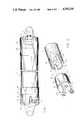
- FIG. 1is a side elevation of the composite drive shaft of the invention with parts broken away in section;
- FIG. 2is an exploded perspective view showing an end of the fiber reinforced resin tubular member and the yoke;
- FIG. 3is an exploded perspective view of a modified form of the invention showing the ends of the tubular member and the yoke;
- FIG. 4is a longitudinal section of the connected members as illustrated in FIG. 3;
- FIG. 5is a transverse section taken along line 5--5 of FIG. 4.
- FIG. 1illustrates a composite drive shaft composed of a fiber reinforced resin shaft or tubular member 1 and a pair of metal yokes 2, formed of aluminum or the like, each of which is connected to an end of the tubular member 1.
- Tubular member 1is formed of a fibrous material such as glass fibers, or a combination of glass and graphite fibers, which are wound in a pattern to provide the desired mechanical properties in the tubular member.
- a combination of different winding patternscan be used, such as substantially circumferential windings, helical windings and substantially longitudinal windings.
- the particular winding pattern and fibrous material employed in forming tubular member 1is conventional and in itself forms no part of the invention.
- the fibrous material in tubular member 1is bonded together by a cured thermosetting resin, such as an epoxy or polyester resin.
- each yoke 2is provided with a generally cylindrical sleeve portion 3 and a plurality of longitudinal raised ribs or bosses 4 are formed on the outer surface of the sleeve 3. As shown, four ribs 4 are utilized, but depending upon the particular application, one or more such ribs can be employed. Each rib is provided with a generally curved or rounded outer end 5 as shown in FIG. 2.
- the ends of the tubular member 1are provided with longitudinal slots 6 which receive the ribs 4 on yoke 2.
- Each slot 6is bordered by a pair of generally parallel walls 7 and a generally curved or rounded base 8 which engages the rounded end 5 of the respective rib 4.
- the ribs 4can be formed on the inner surface of the sleeve 3, and the sleeve inserted over the tubular member 1, so that the ribs are received in slots 6.
- tubular member 1 and yokes 2are bonded together, preferably by a thermosetting resin or an adhesive system.
- a fibrous material impregnated with a thermosetting resincan be wound around the outer surface of tubular member 1 and yoke 2 and across the joint therebetween, as indicated by 10.
- the outer surfaces of ribs 4are substantially flush with the outer surface of the tubular member 1 so that the resulting windings 10 will have a smooth outer surface or contour.
- a metal clamping bandcan be clamped over the joint in place of the fibrous windings 10.
- Each yoke 2is provided with an axial bore which is normally enclosed by a plug 11.
- the composite structureincluding tubular member 1 and yokes 2
- the composite structurecan be supported by a central shaft that extends through the axial openings in yokes 2.
- the shaftserves to properly align the two yokes 2 and tubular member 1 during winding of the layer 10. After the windings have been applied, the shaft is removed from the composite structure and the axial bores are closed by the plugs 11.
- FIGS. 3-5illustrate a modified form of the invention in which the composite drive shaft includes a fiber reinforced resin shaft or tubular member 12 and a pair of metal yokes 13.
- the cylindrical sleeve portion 14 of each yoke 13is formed with a plurality of longitudinally extending raised ribs or bosses 15. As illustrated in FIG. 5, sleeve portion 14 includes six ribs 15 but it is contemplated that any number of ribs can be utilized.
- Each rib 15is bordered by a pair of angularly extending sides 16 which are connected together by a generally square end 17. As best illustrated in FIG. 4, the portions of sleeve 14 extending between the bases of adjacent ribs 15 are formed with recesses 18 which extend at an acute angle of about 10° to 20° with respect to the axis of sleeve 14.
- each end of tubular member 12is provided with a plurality of tongues 19 which border slots 20.
- Tongues 19taper or converge inwardly, as illustrated in FIG. 3, and are received in the spaces between ribs 15 on sleeve 14.
- the tongues 19are relatively flexible and the tips 21 of the tongues are bent or deformed inwardly and are received within the angular recesses 18 in sleeve 14.
- the bases of slots 20bottom out against the ends 17 of ribs 15 and the contiguous surfaces of the tubular member 12 and sleeve 14 are bonded together by an adhesive such as a thermosetting resin. Bonding of the bent ends 21 of tongues 19 within recesses 18 serves to enhance the connection between the tubular member 12 and yokes 13.
- windings 22 of a fibrous material impregnated with a thermosetting resincan be applied over the outer surface of the tubular member 12 and yokes 13 to bridge the joint between the members.
- the inventionprovides an improved mechanical interlock between the fiber reinforced resin tubular member or shaft and the metal yokes in which the torsional load is transmitted between the ribs and slots rather than through an adhesive bonded interface between the members.
- the composite drive shafthas a substantially reduced weight over a conventional steel drive shaft and provides reduced operational noise in service.
Landscapes
- Engineering & Computer Science (AREA)
- General Engineering & Computer Science (AREA)
- Mechanical Engineering (AREA)
- Ocean & Marine Engineering (AREA)
- Shafts, Cranks, Connecting Bars, And Related Bearings (AREA)
Abstract
Description
Claims (7)
Priority Applications (2)
| Application Number | Priority Date | Filing Date | Title |
|---|---|---|---|
| US07/075,234US4792320A (en) | 1985-09-18 | 1987-07-17 | Composite tubular structure |
| US07/158,839US4853060A (en) | 1987-07-17 | 1988-02-22 | Method of forming a composite tubular structure |
Applications Claiming Priority (2)
| Application Number | Priority Date | Filing Date | Title |
|---|---|---|---|
| US77719185A | 1985-09-18 | 1985-09-18 | |
| US07/075,234US4792320A (en) | 1985-09-18 | 1987-07-17 | Composite tubular structure |
Related Parent Applications (1)
| Application Number | Title | Priority Date | Filing Date |
|---|---|---|---|
| US77719185AContinuation | 1985-09-18 | 1985-09-18 |
Related Child Applications (1)
| Application Number | Title | Priority Date | Filing Date |
|---|---|---|---|
| US07/158,839DivisionUS4853060A (en) | 1987-07-17 | 1988-02-22 | Method of forming a composite tubular structure |
Publications (1)
| Publication Number | Publication Date |
|---|---|
| US4792320Atrue US4792320A (en) | 1988-12-20 |
Family
ID=26756597
Family Applications (1)
| Application Number | Title | Priority Date | Filing Date |
|---|---|---|---|
| US07/075,234Expired - LifetimeUS4792320A (en) | 1985-09-18 | 1987-07-17 | Composite tubular structure |
Country Status (1)
| Country | Link |
|---|---|
| US (1) | US4792320A (en) |
Cited By (47)
| Publication number | Priority date | Publication date | Assignee | Title |
|---|---|---|---|---|
| US4930204A (en)* | 1989-02-01 | 1990-06-05 | A. O. Smith Corporation | Method of forming composite tubular structure |
| US5230661A (en)* | 1990-04-20 | 1993-07-27 | Wolfgang Schreiber | Shaft assembly including a tube of fiber synthetic composite material and a connection element of rigid material and method of making it |
| US5234378A (en)* | 1990-08-06 | 1993-08-10 | Ford Motor Company | Balanced rotary assembly |
| US5318374A (en)* | 1992-09-23 | 1994-06-07 | The Boeing Company | Composite tube structure |
| US5421781A (en)* | 1992-04-03 | 1995-06-06 | Turboflex Limited | Couplings |
| US5469931A (en)* | 1992-11-30 | 1995-11-28 | Jidosha Buhin Kogyo Co., Ltd. | Propeller shaft arrangement |
| US5553964A (en)* | 1992-10-06 | 1996-09-10 | Gkn Automotive Ag | Mechanical tubular element such as transmission shaft of a motor vehicle |
| US6080020A (en)* | 1998-05-28 | 2000-06-27 | The Whitaker Corporation | Ground plane for a filtered electrical connector |
| US6352385B1 (en)* | 2000-07-31 | 2002-03-05 | General Electric Company | Mechanical coupling for cooperating rotatable members |
| US20030224863A1 (en)* | 2002-04-04 | 2003-12-04 | Simboli Andrew R. | Vehicular driveshaft assembly |
| US20040162150A1 (en)* | 2002-12-13 | 2004-08-19 | Herbert Cermak | Driveshaft and method and device for producing same |
| US20040176797A1 (en)* | 2003-03-04 | 2004-09-09 | Nmt Medical, Inc. | Magnetic attachment systems |
| US6792660B1 (en)* | 2002-12-30 | 2004-09-21 | Torque-Traction Technologies, Inc. | Method for manufacturing a driveshaft assembly that is balanced for rotation |
| US6936058B2 (en) | 2000-10-18 | 2005-08-30 | Nmt Medical, Inc. | Over-the-wire interlock attachment/detachment mechanism |
| US20080129041A1 (en)* | 2006-12-02 | 2008-06-05 | The Boeing Company | Composite tube having co-bonded end fittings |
| US20080157519A1 (en)* | 2006-11-01 | 2008-07-03 | Mullen James M | Composite tube assemblies and methods of forming the same |
| US20090036877A1 (en)* | 2007-08-01 | 2009-02-05 | Boston Scientific Scimed, Inc. | Spring detach joint for delivering a detachable implantable device |
| US20090116898A1 (en)* | 2007-11-02 | 2009-05-07 | Wanthal Steven P | Joint for hybrid composite items |
| US20110180273A1 (en)* | 2010-01-28 | 2011-07-28 | Sunstone Technologies, Llc | Tapered Spline Connection for Drill Pipe, Casing, and Tubing |
| US20110245832A1 (en)* | 2010-03-31 | 2011-10-06 | Stryker Trauma Gmbh | Wrapped connection between carbon fiber shaft and metal part |
| US20110251692A1 (en)* | 2010-04-12 | 2011-10-13 | Mclaughlin Colm | Expandable Vertebral Implant |
| US20120115621A1 (en)* | 2009-08-19 | 2012-05-10 | Bayerische Motoren Werke Aktiengesellschaft | Torque Transmission Device |
| US20130089371A1 (en)* | 2010-05-04 | 2013-04-11 | Mona Elisabet WINKVIST | Pre-tensioning device between two elements mounted in spaced relation on an axle |
| EP2602497A1 (en)* | 2011-12-05 | 2013-06-12 | Magna Steyr Fahrzeugtechnik AG & Co KG | Connection between two components and method for connecting two components |
| EP2568185A3 (en)* | 2011-09-07 | 2013-12-18 | Technische Universität Darmstadt | Rotating shaft and connection element |
| US20140013873A1 (en)* | 2012-07-13 | 2014-01-16 | Korea Atomic Energy Research Institute | Cam-locking dissimilar material sleeve |
| US20140112708A1 (en)* | 2012-10-18 | 2014-04-24 | Epsilon Composite | Process for bonding two parts subjected to tensile forces, bonded parts obtained |
| US8739861B2 (en) | 2010-07-16 | 2014-06-03 | Sunstone Technologies, Llc | Electrical wiring for drill pipe, casing, and tubing |
| US20150211832A1 (en)* | 2014-01-29 | 2015-07-30 | Raytheon Company | Internally coupleable joint |
| US20150224902A1 (en)* | 2012-09-24 | 2015-08-13 | Ts Tech Co., Ltd. | Attachment structure for connecting member for seat and attachable member, and seat structure |
| US20150284957A1 (en)* | 2014-04-08 | 2015-10-08 | Goodrich Corporation | Struts and methods utilizing a compression collar |
| US20150330457A1 (en)* | 2012-12-18 | 2015-11-19 | Yamada Manufacturing Co., Ltd. | Joint structure of yoke and shaft and joining method therefor |
| US9345489B2 (en) | 2010-03-31 | 2016-05-24 | Stryker European Holdings I, Llc | Reaming device with carbon fiber shaft and molded interface element |
| CN106715931A (en)* | 2014-11-17 | 2017-05-24 | Ntn株式会社 | Power transmission shaft |
| US9707091B2 (en) | 2010-04-12 | 2017-07-18 | Globus Medical, Inc. | Expandable vertebral implant |
| US9777764B2 (en)* | 2015-12-09 | 2017-10-03 | Hsiao-Lin Lee | Transmission shaft assembly |
| US9808349B2 (en) | 2010-04-12 | 2017-11-07 | Globus Medical Inc | Expandable vertebral implant |
| US9913735B2 (en) | 2010-04-12 | 2018-03-13 | Globus Medical, Inc. | Angling inserter tool for expandable vertebral implant |
| US10006255B2 (en) | 2010-01-28 | 2018-06-26 | Sunstone Technologies, Llc | Tapered spline connection for drill pipe, casing, and tubing |
| US10130489B2 (en) | 2010-04-12 | 2018-11-20 | Globus Medical, Inc. | Expandable vertebral implant |
| US20190063504A1 (en)* | 2017-08-25 | 2019-02-28 | Kennametal Inc. | Spline drive drill steel couplers |
| US10344794B2 (en) | 2016-11-18 | 2019-07-09 | Dana Automotive Systems Group, Llc | Open composite shaft |
| EP3647619A1 (en)* | 2018-10-29 | 2020-05-06 | Hamilton Sundstrand Corporation | Drive shaft assembled from plural parts of composite material with bellow couplings |
| US20220099228A1 (en)* | 2016-06-08 | 2022-03-31 | Avtechtyee Inc. | Fitting collar and tube-fitting assemblies incorporating fitting collars |
| US11426287B2 (en) | 2010-04-12 | 2022-08-30 | Globus Medical Inc. | Expandable vertebral implant |
| US11512734B2 (en)* | 2019-06-06 | 2022-11-29 | Jilin University | Shaft-tube joint structure of carbon fiber reinforced plastic drive shaft |
| WO2023218714A1 (en)* | 2022-05-11 | 2023-11-16 | 三菱重工業株式会社 | Power transmission shaft, and vehicle equipped with same |
Citations (15)
| Publication number | Priority date | Publication date | Assignee | Title |
|---|---|---|---|---|
| US889786A (en)* | 1906-10-18 | 1908-06-02 | Universal Railway Supply Company | Connector for electric wires. |
| US2470631A (en)* | 1943-07-28 | 1949-05-17 | Westinghouse Electric Corp | Sliding joint for transmission lines |
| US2890900A (en)* | 1955-06-27 | 1959-06-16 | Goodall Rubber Co | Hose coupling having longitudinal locking means |
| US3623753A (en)* | 1969-12-08 | 1971-11-30 | Smith International | Pipe coupling for a sealed fluid conductor |
| US4238540A (en)* | 1979-05-29 | 1980-12-09 | Celanese Corporation | Fiber reinforced composite shaft with metallic connector sleeves mounted by connector ring interlock |
| US4248062A (en)* | 1979-10-05 | 1981-02-03 | Shakespeare Company | Drive shaft assembly and method for making same |
| US4279275A (en)* | 1979-08-06 | 1981-07-21 | Ford Aerospace & Communications Corporation | Mechanical joinder of composite shaft to metallic end members |
| GB2071272A (en)* | 1980-03-11 | 1981-09-16 | Loehr & Bromkamp Gmbh | Drive shaft |
| EP0045724A1 (en)* | 1980-07-31 | 1982-02-10 | CASAGRANDE SpA | Joint with clamping strip |
| US4341482A (en)* | 1980-09-22 | 1982-07-27 | Sanford Research Company | Housing assembly for fluid marking device |
| US4358284A (en)* | 1979-12-21 | 1982-11-09 | Felten & Guilleaume Carlswerk Ag | Fiber-reinforced driveshaft |
| US4362521A (en)* | 1979-05-10 | 1982-12-07 | Ciba-Geigy Corporation | Power transmission shaft |
| US4380443A (en)* | 1979-11-17 | 1983-04-19 | Felten & Guilleaume Carlswerk Aktiengesellschaft | Fiber-reinforced drive shaft |
| US4421497A (en)* | 1979-11-17 | 1983-12-20 | Felten & Guilleaume Energietechnik Gmbh | Fiber-reinforced drive shaft |
| US4451245A (en)* | 1980-03-01 | 1984-05-29 | Daimler-Benz Aktiengesellschaft | Coupling connection for a fiber reinforced synthetic resin pipe |
- 1987
- 1987-07-17USUS07/075,234patent/US4792320A/ennot_activeExpired - Lifetime
Patent Citations (15)
| Publication number | Priority date | Publication date | Assignee | Title |
|---|---|---|---|---|
| US889786A (en)* | 1906-10-18 | 1908-06-02 | Universal Railway Supply Company | Connector for electric wires. |
| US2470631A (en)* | 1943-07-28 | 1949-05-17 | Westinghouse Electric Corp | Sliding joint for transmission lines |
| US2890900A (en)* | 1955-06-27 | 1959-06-16 | Goodall Rubber Co | Hose coupling having longitudinal locking means |
| US3623753A (en)* | 1969-12-08 | 1971-11-30 | Smith International | Pipe coupling for a sealed fluid conductor |
| US4362521A (en)* | 1979-05-10 | 1982-12-07 | Ciba-Geigy Corporation | Power transmission shaft |
| US4238540A (en)* | 1979-05-29 | 1980-12-09 | Celanese Corporation | Fiber reinforced composite shaft with metallic connector sleeves mounted by connector ring interlock |
| US4279275A (en)* | 1979-08-06 | 1981-07-21 | Ford Aerospace & Communications Corporation | Mechanical joinder of composite shaft to metallic end members |
| US4248062A (en)* | 1979-10-05 | 1981-02-03 | Shakespeare Company | Drive shaft assembly and method for making same |
| US4380443A (en)* | 1979-11-17 | 1983-04-19 | Felten & Guilleaume Carlswerk Aktiengesellschaft | Fiber-reinforced drive shaft |
| US4421497A (en)* | 1979-11-17 | 1983-12-20 | Felten & Guilleaume Energietechnik Gmbh | Fiber-reinforced drive shaft |
| US4358284A (en)* | 1979-12-21 | 1982-11-09 | Felten & Guilleaume Carlswerk Ag | Fiber-reinforced driveshaft |
| US4451245A (en)* | 1980-03-01 | 1984-05-29 | Daimler-Benz Aktiengesellschaft | Coupling connection for a fiber reinforced synthetic resin pipe |
| GB2071272A (en)* | 1980-03-11 | 1981-09-16 | Loehr & Bromkamp Gmbh | Drive shaft |
| EP0045724A1 (en)* | 1980-07-31 | 1982-02-10 | CASAGRANDE SpA | Joint with clamping strip |
| US4341482A (en)* | 1980-09-22 | 1982-07-27 | Sanford Research Company | Housing assembly for fluid marking device |
Cited By (99)
| Publication number | Priority date | Publication date | Assignee | Title |
|---|---|---|---|---|
| US4930204A (en)* | 1989-02-01 | 1990-06-05 | A. O. Smith Corporation | Method of forming composite tubular structure |
| US5230661A (en)* | 1990-04-20 | 1993-07-27 | Wolfgang Schreiber | Shaft assembly including a tube of fiber synthetic composite material and a connection element of rigid material and method of making it |
| US5234378A (en)* | 1990-08-06 | 1993-08-10 | Ford Motor Company | Balanced rotary assembly |
| US5421781A (en)* | 1992-04-03 | 1995-06-06 | Turboflex Limited | Couplings |
| US5665187A (en)* | 1992-04-03 | 1997-09-09 | Turboflex Limited | Method for connecting composite drive shaft to annular member |
| US5318374A (en)* | 1992-09-23 | 1994-06-07 | The Boeing Company | Composite tube structure |
| US5553964A (en)* | 1992-10-06 | 1996-09-10 | Gkn Automotive Ag | Mechanical tubular element such as transmission shaft of a motor vehicle |
| US5469931A (en)* | 1992-11-30 | 1995-11-28 | Jidosha Buhin Kogyo Co., Ltd. | Propeller shaft arrangement |
| US6080020A (en)* | 1998-05-28 | 2000-06-27 | The Whitaker Corporation | Ground plane for a filtered electrical connector |
| US6352385B1 (en)* | 2000-07-31 | 2002-03-05 | General Electric Company | Mechanical coupling for cooperating rotatable members |
| US9463006B2 (en) | 2000-10-18 | 2016-10-11 | W.L. Gore & Associates, Inc. | Over-the-wire interlock attachment/detachment mechanism |
| US8398694B2 (en) | 2000-10-18 | 2013-03-19 | W.L. Gore & Associates, Inc. | Over-the-wire interlock attachment/detachment mechanism |
| US6936058B2 (en) | 2000-10-18 | 2005-08-30 | Nmt Medical, Inc. | Over-the-wire interlock attachment/detachment mechanism |
| US6855061B2 (en)* | 2002-04-04 | 2005-02-15 | Dana Corporation | Vehicular driveshaft assembly |
| US20030224863A1 (en)* | 2002-04-04 | 2003-12-04 | Simboli Andrew R. | Vehicular driveshaft assembly |
| US6928712B2 (en)* | 2002-12-13 | 2005-08-16 | Gkn Driveline Deutschland Gmbh | Driveshaft and method and device for producing same |
| US20040162150A1 (en)* | 2002-12-13 | 2004-08-19 | Herbert Cermak | Driveshaft and method and device for producing same |
| US6792660B1 (en)* | 2002-12-30 | 2004-09-21 | Torque-Traction Technologies, Inc. | Method for manufacturing a driveshaft assembly that is balanced for rotation |
| US7618435B2 (en) | 2003-03-04 | 2009-11-17 | Nmt Medical, Inc. | Magnetic attachment systems |
| US20040176797A1 (en)* | 2003-03-04 | 2004-09-09 | Nmt Medical, Inc. | Magnetic attachment systems |
| US8205315B2 (en)* | 2006-11-01 | 2012-06-26 | Tyee Aircraft | Composite tube assemblies and methods of forming the same |
| US20080157519A1 (en)* | 2006-11-01 | 2008-07-03 | Mullen James M | Composite tube assemblies and methods of forming the same |
| US20080129041A1 (en)* | 2006-12-02 | 2008-06-05 | The Boeing Company | Composite tube having co-bonded end fittings |
| US8713895B2 (en)* | 2006-12-02 | 2014-05-06 | The Boeing Company | Composite tube having co-bonded end fittings |
| US20080131630A1 (en)* | 2006-12-02 | 2008-06-05 | The Boeing Company | Composite tube having cobonded end fittings and method of making same |
| US8414724B2 (en) | 2006-12-02 | 2013-04-09 | The Boeing Company | Composite tube having cobonded end fittings and method of making same |
| US8365502B2 (en)* | 2006-12-02 | 2013-02-05 | The Boeing Company | Composite tube having co-bonded end fittings |
| US9155649B2 (en)* | 2007-08-01 | 2015-10-13 | Boston Scientific Scimed, Inc. | Spring detach joint for delivering a detachable implantable device |
| US20090036877A1 (en)* | 2007-08-01 | 2009-02-05 | Boston Scientific Scimed, Inc. | Spring detach joint for delivering a detachable implantable device |
| US20130317594A1 (en)* | 2007-08-01 | 2013-11-28 | Christopher Nardone | Spring detach joint for delivering a detachable implantable device |
| US8500773B2 (en)* | 2007-08-01 | 2013-08-06 | Boston Scientific Scimed, Inc. | Spring detach joint for delivering a detachable implantable device |
| US8430759B2 (en)* | 2007-11-02 | 2013-04-30 | The Boeing Company | Joint for composite tube |
| US20120183347A1 (en)* | 2007-11-02 | 2012-07-19 | The Boeing Company | Joint for composite tube |
| US20090116898A1 (en)* | 2007-11-02 | 2009-05-07 | Wanthal Steven P | Joint for hybrid composite items |
| US8161619B2 (en)* | 2007-11-02 | 2012-04-24 | The Boeing Company | Joint for hybrid composite items |
| US20120115621A1 (en)* | 2009-08-19 | 2012-05-10 | Bayerische Motoren Werke Aktiengesellschaft | Torque Transmission Device |
| US8398493B2 (en)* | 2009-08-19 | 2013-03-19 | Bayerische Motoren Werke Aktiengesellschaft | Torque transmission device |
| US10060197B2 (en) | 2010-01-28 | 2018-08-28 | Sunstone Technologies, Llc | Tapered spline connection for drill pipe, casing, and tubing |
| US10066446B2 (en) | 2010-01-28 | 2018-09-04 | Sunstone Technologies, Llc | Tapered spline connection for drill pipe, casing, and tubing |
| US10006255B2 (en) | 2010-01-28 | 2018-06-26 | Sunstone Technologies, Llc | Tapered spline connection for drill pipe, casing, and tubing |
| US9845645B2 (en) | 2010-01-28 | 2017-12-19 | Sunstone Technologies, Llc | Tapered spline connection for drill pipe, casing, and tubing |
| US20110180273A1 (en)* | 2010-01-28 | 2011-07-28 | Sunstone Technologies, Llc | Tapered Spline Connection for Drill Pipe, Casing, and Tubing |
| US20110245832A1 (en)* | 2010-03-31 | 2011-10-06 | Stryker Trauma Gmbh | Wrapped connection between carbon fiber shaft and metal part |
| US9345489B2 (en) | 2010-03-31 | 2016-05-24 | Stryker European Holdings I, Llc | Reaming device with carbon fiber shaft and molded interface element |
| US9808349B2 (en) | 2010-04-12 | 2017-11-07 | Globus Medical Inc | Expandable vertebral implant |
| US11426287B2 (en) | 2010-04-12 | 2022-08-30 | Globus Medical Inc. | Expandable vertebral implant |
| US10369000B2 (en) | 2010-04-12 | 2019-08-06 | Globus Medical, Inc. | Expandable vertebral implant |
| US10130489B2 (en) | 2010-04-12 | 2018-11-20 | Globus Medical, Inc. | Expandable vertebral implant |
| US11564803B2 (en) | 2010-04-12 | 2023-01-31 | Globus Medical, Inc. | Expandable vertebral implant |
| US20110251692A1 (en)* | 2010-04-12 | 2011-10-13 | Mclaughlin Colm | Expandable Vertebral Implant |
| US9707091B2 (en) | 2010-04-12 | 2017-07-18 | Globus Medical, Inc. | Expandable vertebral implant |
| US9579211B2 (en)* | 2010-04-12 | 2017-02-28 | Globus Medical, Inc. | Expandable vertebral implant |
| US12279971B2 (en) | 2010-04-12 | 2025-04-22 | Globus Medical, Inc. | Angling inserter tool for expandable vertebral implant |
| US11298243B2 (en) | 2010-04-12 | 2022-04-12 | Globus Medical, Inc. | Angling inserter tool for expandable vertebral implant |
| US10500057B2 (en) | 2010-04-12 | 2019-12-10 | Globus Medical, Inc. | Expandable vertebral implant |
| US9913735B2 (en) | 2010-04-12 | 2018-03-13 | Globus Medical, Inc. | Angling inserter tool for expandable vertebral implant |
| US10492928B2 (en) | 2010-04-12 | 2019-12-03 | Globus Medical, Inc. | Angling inserter tool for expandable vertebral implant |
| US9474621B2 (en) | 2010-04-12 | 2016-10-25 | Globus Medical, Inc. | Expandable vertebral implant |
| US20130089371A1 (en)* | 2010-05-04 | 2013-04-11 | Mona Elisabet WINKVIST | Pre-tensioning device between two elements mounted in spaced relation on an axle |
| US8739861B2 (en) | 2010-07-16 | 2014-06-03 | Sunstone Technologies, Llc | Electrical wiring for drill pipe, casing, and tubing |
| EP2568185A3 (en)* | 2011-09-07 | 2013-12-18 | Technische Universität Darmstadt | Rotating shaft and connection element |
| US9664228B2 (en)* | 2011-12-05 | 2017-05-30 | Magna Steyr Fahrzeugtechnik Ag & Co Kg | Connection between two parts and method for connecting two parts |
| US20140363220A1 (en)* | 2011-12-05 | 2014-12-11 | Magna Steyr Fahrzeugtechnik Ag & Co Kg | Connection Between Two Parts and Method for Connecting Two Parts |
| CN103975168A (en)* | 2011-12-05 | 2014-08-06 | 马格纳斯泰尔汽车技术两合公司 | Connection between two components and method for connecting two components |
| WO2013083526A1 (en)* | 2011-12-05 | 2013-06-13 | Magna Steyr Fahrzeugtechnik Ag & Co Kg | Connection between two components and method for connecting two components |
| EP2602496A1 (en)* | 2011-12-05 | 2013-06-12 | Magna Steyr Fahrzeugtechnik AG & Co KG | Connection between two components and method for connecting two components |
| EP2602497A1 (en)* | 2011-12-05 | 2013-06-12 | Magna Steyr Fahrzeugtechnik AG & Co KG | Connection between two components and method for connecting two components |
| US9116025B2 (en)* | 2012-07-13 | 2015-08-25 | Korea Atomic Energy Research Institute | Cam-locking dissimilar material sleeve |
| US20140013873A1 (en)* | 2012-07-13 | 2014-01-16 | Korea Atomic Energy Research Institute | Cam-locking dissimilar material sleeve |
| US20150224902A1 (en)* | 2012-09-24 | 2015-08-13 | Ts Tech Co., Ltd. | Attachment structure for connecting member for seat and attachable member, and seat structure |
| US20140112708A1 (en)* | 2012-10-18 | 2014-04-24 | Epsilon Composite | Process for bonding two parts subjected to tensile forces, bonded parts obtained |
| US9227375B2 (en)* | 2012-10-18 | 2016-01-05 | Epsilon Composite | Process for bonding two parts subjected to tensile forces, bonded parts obtained |
| US20150330457A1 (en)* | 2012-12-18 | 2015-11-19 | Yamada Manufacturing Co., Ltd. | Joint structure of yoke and shaft and joining method therefor |
| US10634473B2 (en)* | 2014-01-29 | 2020-04-28 | Raytheon Company | Internally coupleable joint |
| US20150211832A1 (en)* | 2014-01-29 | 2015-07-30 | Raytheon Company | Internally coupleable joint |
| US11009326B2 (en) | 2014-01-29 | 2021-05-18 | Raytheon Company | Internally coupleable joint |
| US10233644B2 (en) | 2014-04-08 | 2019-03-19 | Goodrich Corporation | Method of manufacturing a composite tube |
| US20150284957A1 (en)* | 2014-04-08 | 2015-10-08 | Goodrich Corporation | Struts and methods utilizing a compression collar |
| US9441374B2 (en)* | 2014-04-08 | 2016-09-13 | Goodrich Corporation | Struts and methods utilizing a compression collar |
| CN106715931A (en)* | 2014-11-17 | 2017-05-24 | Ntn株式会社 | Power transmission shaft |
| CN106715931B (en)* | 2014-11-17 | 2019-12-24 | Ntn株式会社 | Power transmission shaft |
| EP3222862A4 (en)* | 2014-11-17 | 2018-06-27 | NTN Corporation | Power transmission shaft |
| US9777764B2 (en)* | 2015-12-09 | 2017-10-03 | Hsiao-Lin Lee | Transmission shaft assembly |
| US20220099228A1 (en)* | 2016-06-08 | 2022-03-31 | Avtechtyee Inc. | Fitting collar and tube-fitting assemblies incorporating fitting collars |
| US11927291B2 (en) | 2016-06-08 | 2024-03-12 | Avtechtyee Inc. | Methods for coupling a fitting to a tube using a collar |
| US12372188B2 (en) | 2016-06-08 | 2025-07-29 | AvtechTyee, Inc. | Fitting collar and tube-fitting assemblies incorporating fitting collars |
| US11940076B2 (en)* | 2016-06-08 | 2024-03-26 | Avtechtyee Inc. | Fitting collar and tube-fitting assemblies incorporating fitting collars |
| US10344794B2 (en) | 2016-11-18 | 2019-07-09 | Dana Automotive Systems Group, Llc | Open composite shaft |
| CN109424327B (en)* | 2017-08-25 | 2022-04-15 | 肯纳金属公司 | Spline driving type drill steel connector |
| US10859122B2 (en)* | 2017-08-25 | 2020-12-08 | Kennametal Inc. | Spline drive drill steel couplers |
| US20190063504A1 (en)* | 2017-08-25 | 2019-02-28 | Kennametal Inc. | Spline drive drill steel couplers |
| CN109424327A (en)* | 2017-08-25 | 2019-03-05 | 肯纳金属公司 | Spline drive-type drill steel connector |
| AU2018204593B2 (en)* | 2017-08-25 | 2023-07-20 | Kennametal Inc. | Spline drive drill steel couplers |
| US11396904B2 (en) | 2018-10-29 | 2022-07-26 | Hamilton Sundstrand Corporation | Composite drive shafts |
| US12152633B2 (en) | 2018-10-29 | 2024-11-26 | Hamilton Sundstrand Corporation | Composite drive shafts |
| EP3647619A1 (en)* | 2018-10-29 | 2020-05-06 | Hamilton Sundstrand Corporation | Drive shaft assembled from plural parts of composite material with bellow couplings |
| US11512734B2 (en)* | 2019-06-06 | 2022-11-29 | Jilin University | Shaft-tube joint structure of carbon fiber reinforced plastic drive shaft |
| JP2023167170A (en)* | 2022-05-11 | 2023-11-24 | 三菱重工業株式会社 | Power transmission shaft and vehicle including the same |
| WO2023218714A1 (en)* | 2022-05-11 | 2023-11-16 | 三菱重工業株式会社 | Power transmission shaft, and vehicle equipped with same |
Similar Documents
| Publication | Publication Date | Title |
|---|---|---|
| US4792320A (en) | Composite tubular structure | |
| US4664644A (en) | Fiber reinforced plastic drive shaft and method of manufacturing thereof | |
| CA1162408A (en) | Flexible coupling | |
| US4380443A (en) | Fiber-reinforced drive shaft | |
| US4930204A (en) | Method of forming composite tubular structure | |
| US4238540A (en) | Fiber reinforced composite shaft with metallic connector sleeves mounted by connector ring interlock | |
| US4358284A (en) | Fiber-reinforced driveshaft | |
| US4236386A (en) | Fiber reinforced composite shaft with metallic connector sleeves mounted by a polygonal surface interlock | |
| US5836712A (en) | Joint between two components | |
| US4932924A (en) | Torque transmitting assembly | |
| US4565356A (en) | Bushing construction for a fiber reinforced plastic leaf spring | |
| US6409606B1 (en) | Power transmission shaft | |
| US5851152A (en) | Drive shaft with reinforced plastic tube and a joint-connecting body connected nonrotatably endwise | |
| US4853060A (en) | Method of forming a composite tubular structure | |
| US4838833A (en) | Fiber reinforced resin drive shaft having improved resistance to torsional buckling | |
| EP0138896A1 (en) | Composite shafts. | |
| US4773891A (en) | Drive shaft of fibre-reinforced plastic material | |
| US5553964A (en) | Mechanical tubular element such as transmission shaft of a motor vehicle | |
| GB2051303A (en) | Fibre-reinforced composite shaft with metallic connector sleeves | |
| GB2124735A (en) | Drive shaft | |
| US5043217A (en) | Composite to metal joint for torsional shafts | |
| US4569667A (en) | Flexible coupling | |
| US5562014A (en) | Fly wheel arrangement | |
| US5713246A (en) | Method for fixing an energy-storing flywheel with pretension on a support and unit comprising an energy storing flywheel | |
| CA1288963C (en) | Composite tubular structure |
Legal Events
| Date | Code | Title | Description |
|---|---|---|---|
| STCF | Information on status: patent grant | Free format text:PATENTED CASE | |
| CC | Certificate of correction | ||
| FEPP | Fee payment procedure | Free format text:PAYOR NUMBER ASSIGNED (ORIGINAL EVENT CODE: ASPN); ENTITY STATUS OF PATENT OWNER: LARGE ENTITY | |
| FEPP | Fee payment procedure | Free format text:PAYER NUMBER DE-ASSIGNED (ORIGINAL EVENT CODE: RMPN); ENTITY STATUS OF PATENT OWNER: LARGE ENTITY Free format text:PAYOR NUMBER ASSIGNED (ORIGINAL EVENT CODE: ASPN); ENTITY STATUS OF PATENT OWNER: LARGE ENTITY | |
| FPAY | Fee payment | Year of fee payment:4 | |
| FPAY | Fee payment | Year of fee payment:8 | |
| AS | Assignment | Owner name:AOS HOLDING COMPANY, DELAWARE Free format text:ASSIGNMENT OF ASSIGNORS INTEREST;ASSIGNOR:A.O. SMITH CORPORATION;REEL/FRAME:008512/0352 Effective date:19970416 | |
| AS | Assignment | Owner name:R.J. TOWER CORPORATION, MICHIGAN Free format text:ASSIGNMENT OF ASSIGNORS INTEREST;ASSIGNOR:AOS HOLDING COMPANY;REEL/FRAME:008595/0875 Effective date:19970418 | |
| FPAY | Fee payment | Year of fee payment:12 | |
| FEPP | Fee payment procedure | Free format text:PAYER NUMBER DE-ASSIGNED (ORIGINAL EVENT CODE: RMPN); ENTITY STATUS OF PATENT OWNER: LARGE ENTITY Free format text:PAYOR NUMBER ASSIGNED (ORIGINAL EVENT CODE: ASPN); ENTITY STATUS OF PATENT OWNER: LARGE ENTITY | |
| AS | Assignment | Owner name:STANDARD FEDERAL BANK, AS COLLATERAL AGENT, MICHIG Free format text:SECURITY INTEREST;ASSIGNOR:R.J. TOWER CORPORATION;REEL/FRAME:015953/0001 Effective date:20040524 | |
| AS | Assignment | Owner name:STANDARD FEDERAL BANK, AS COLLATERAL AGENT, MICHIG Free format text:SECURITY AGREEMENT;ASSIGNOR:R.J. TOWER CORPORATION;REEL/FRAME:016651/0138 Effective date:20040524 |